EP2841823B1 - Support frame seal with reduced space requirements - Google Patents
Support frame seal with reduced space requirements Download PDFInfo
- Publication number
- EP2841823B1 EP2841823B1 EP12795402.2A EP12795402A EP2841823B1 EP 2841823 B1 EP2841823 B1 EP 2841823B1 EP 12795402 A EP12795402 A EP 12795402A EP 2841823 B1 EP2841823 B1 EP 2841823B1
- Authority
- EP
- European Patent Office
- Prior art keywords
- support frame
- ring
- sealing
- seal according
- sealing profile
- Prior art date
- Legal status (The legal status is an assumption and is not a legal conclusion. Google has not performed a legal analysis and makes no representation as to the accuracy of the status listed.)
- Not-in-force
Links
Images


Classifications
-
- F—MECHANICAL ENGINEERING; LIGHTING; HEATING; WEAPONS; BLASTING
- F16—ENGINEERING ELEMENTS AND UNITS; GENERAL MEASURES FOR PRODUCING AND MAINTAINING EFFECTIVE FUNCTIONING OF MACHINES OR INSTALLATIONS; THERMAL INSULATION IN GENERAL
- F16J—PISTONS; CYLINDERS; SEALINGS
- F16J15/00—Sealings
- F16J15/02—Sealings between relatively-stationary surfaces
- F16J15/06—Sealings between relatively-stationary surfaces with solid packing compressed between sealing surfaces
- F16J15/10—Sealings between relatively-stationary surfaces with solid packing compressed between sealing surfaces with non-metallic packing
- F16J15/12—Sealings between relatively-stationary surfaces with solid packing compressed between sealing surfaces with non-metallic packing with metal reinforcement or covering
- F16J15/121—Sealings between relatively-stationary surfaces with solid packing compressed between sealing surfaces with non-metallic packing with metal reinforcement or covering with metal reinforcement
- F16J15/122—Sealings between relatively-stationary surfaces with solid packing compressed between sealing surfaces with non-metallic packing with metal reinforcement or covering with metal reinforcement generally parallel to the surfaces
-
- F—MECHANICAL ENGINEERING; LIGHTING; HEATING; WEAPONS; BLASTING
- F16—ENGINEERING ELEMENTS AND UNITS; GENERAL MEASURES FOR PRODUCING AND MAINTAINING EFFECTIVE FUNCTIONING OF MACHINES OR INSTALLATIONS; THERMAL INSULATION IN GENERAL
- F16J—PISTONS; CYLINDERS; SEALINGS
- F16J15/00—Sealings
- F16J15/02—Sealings between relatively-stationary surfaces
- F16J15/06—Sealings between relatively-stationary surfaces with solid packing compressed between sealing surfaces
- F16J15/10—Sealings between relatively-stationary surfaces with solid packing compressed between sealing surfaces with non-metallic packing
- F16J15/12—Sealings between relatively-stationary surfaces with solid packing compressed between sealing surfaces with non-metallic packing with metal reinforcement or covering
- F16J15/121—Sealings between relatively-stationary surfaces with solid packing compressed between sealing surfaces with non-metallic packing with metal reinforcement or covering with metal reinforcement
- F16J15/127—Sealings between relatively-stationary surfaces with solid packing compressed between sealing surfaces with non-metallic packing with metal reinforcement or covering with metal reinforcement the reinforcement being a compression stopper
Definitions
- the present invention relates to girder seals, as used for housing parts with sealing surfaces such as covers or hoods, which are attached to other machine parts.
- the present invention preferably relates to use with carrier frame gaskets.
- the present invention relates in particular to a design in which a sealing profile made of elastomer is vulcanized on the end face of a support frame.
- This embodiment has the advantage that one uses a support frame such as an aluminum support frame once as a support frame for the sealing profile and this also serves as Wegbegrenzer or Verpressungsbegrenzer for the elastomeric seal and additionally absorbs the Verschraubungs characteristic.
- the support frame acts here as Verpressungsbeskyr, so that the seal is in the force shunt.
- the flange on which the gasket is to be mounted has a sufficient width, i. There is enough room for both the sealing profile and sufficient support surface for the support frame available.
- the support frames for such seals are made almost exclusively by stamping, as this is the least expensive option to manufacture.
- Critical locations of a girder seal relative to the flange widths are generally the areas around glands. The reason for this is that, apart from the opening in the support frame through which the screw is guided, the support frame must be guided past inside and outside of the screw, so that in turn results in a closed bore.
- Known special solutions are specified in the prior art.
- the state of the art and also the simplest implementation of these areas in a sealing solution are given if the flange surface of both components provides sufficient width and coverage in all areas. In these cases, it is not necessary to go to the manufacturability limits of the support frame and the bypasses in the region of the screw holes have both outside and inside a sufficient support frame width.
- the flange surface also provides sufficient space to allow two sealing lips to be guided around the threaded connection area, which then rest securely on the two flange sides within all tolerance positions, with the sealing lips in secure contact with both flanges.
- the minimum web width which can be sensibly produced by punching, is approximately at a ratio of 2 to 1. This means that a web must be made at least twice as wide like the thickness of the sheet into which the web is punched. If the carrier sheet is, for example, 1.5 mm thick, the web must be about 3 mm wide, so that it can still be clamped and punched well in the punching tool without major deformations of the web occurring. In many parts, this limit is now undercut and taken into account the disadvantages described below.
- a further reduction of the range of travel would be necessary in order to have a solution for these problem areas at all.
- a narrower deflection of the screw opening on the support frame can only be reduced below the reasonable level, if other disadvantages are accepted. If the width of the web down to a square cross-section (eg support sheet thickness 1.5mm and web width 1.5mm) is reduced, the web is deformed during punching, and it formed by the punching induced indentations and the web can also rotate. The result of the punching in the area is then no longer clearly geometrically predictable. Apart from the deformation, the stiffness of the support frame is greatly affected by these thin webs, which can lead to serious disadvantages when molding the elastomeric seal, since the injection pressure during manufacture can bend the web. Inserting pins in the tool at the holes to limit the deformation of the frame, they can jam and when removing from the mold again around the thin webs bend.
- a punch is a deformation of the sheet edge on a punching line. Punch feeds prevent the carrier frame from being optimally clamped in the injection mold, which may result in over-molding of elastomeric material on the carrier frame and in the screw holes, which is unacceptable.
- Another problem is that due to the insufficient impression, the elastomer material can run into the bore, which then has to be laboriously cleaned again by hand.
- a carrier frame seal is provided with a reduced footprint.
- the carrier frame seal comprises a support frame and a sealing profile made of an elastomeric material which is dull on one end face a support frame is vulcanized.
- the support frame further has recesses for fastening elements. At at least one recess of the support frame on the side at which the sealing profile is vulcanized is interrupted, and extends only on the opposite side of the sealing profile of the at least one recess.
- the support frame is provided on the at least one recess with a ring or with a ring element.
- the ring or the ring element is intended to surround a fastener which is to pass through the recess.
- the ring or the ring element lies in the plane of the support frame.
- the through hole for fixing screws is open through the support frame toward the side of the elastomeric seal.
- the through hole for fastening screws in the support frame has been expanded in this embodiment to a semi-open recess.
- the open side of the recess in the support frame is closed by the ring or the ring member.
- the vulcanized elastomer closes any transitions between the ring or the ring element and the sealing profile.
- the ring has a wall thickness that is less than a width of a ridge that can be stamped into the carrier frame without warping the material of the carrier frame, indenting, or allowing the remaining ridge to twist during punching.
- the ring need not be made by punching, and therefore may have a cross section that can not be achieved with punching.
- the wall thickness of the ring in the radial direction may be smaller than the thickness of the ring in the axial direction.
- the wall thickness of the ring in the radial direction may be less than half as small as the thickness of the ring in the axial direction.
- a material made from the ring has a higher strength than a material from which the carrier frame is made. This can also be achieved that the ring does not bend during operation. It can also be prevented that the ring is bent or destroyed during injection / vulcanization of the sealing profile of the ring.
- a ring of solid material also makes it possible during injection / vulcanization of the sealing profile to ensure that no elastomer material runs into the ring or into a screw leadthrough or the recess.
- At least one further of the recesses is bypassed by the sealing profile, wherein the sealing profile is reduced in the region of at least one deflection in the width.
- This embodiment relates to a seal with an open or ring-shaped recess which is bypassed by a sealing profile which is reduced in width.
- the sealing profile has a sealing lip in the region of the at least one bypass or the recess or ring open on one side, whereas the sealing profile in regions outside the at least one bypass of the recess or ring open on one side Having sealing lips which run side by side.
- the sealing profile has a sealing lip in the region of the at least one bypass, while the sealing profile has two sealing lips in regions outside the at least one bypass which run next to one another.
- sealing profiles with more than two, ie three or more sealing lips in areas outside the at least one bypass.
- two or more sealing lips are present in the remaining flange, in the region of the screw eyes, the number of sealing lips reduced to one.
- two or more sealing lips in the area around a bypass to a single sealing lip can be merged, which diverge after passing around again in two sealing lips. Merging the sealing lips into a single in the area of Fastening protrudes from technically justifiable, since at this point minimal tolerances with optimal compression force are present.
- the one sealing lip is made wider than each of the two adjacent two or more sealing lips.
- the at least one ring is not round outside.
- a square on the outside or oval shape of the ring can help fix the ring better in the carrier layer.
- a ring flattened on the outside or two-sided or oval ring can better absorb or transmit the pressure exerted on it by the screw connection or when applying the elastomer.
- a carrier frame seal with reduced footprint comprises a carrier frame and a sealing profile made of an elastomeric material, which is vulcanized vulcanized to an end face of a carrier frame.
- the support frame is further provided with recesses for fasteners, which are bypassed the sealing profile.
- the width of the sealing profile is reduced in the region of at least one bypass in comparison to a width of the sealing profile in a region without a recess.
- the recess can be carried out, for example, as through holes for fastening screws.
- the one sealing lip is made wider than each of the two adjacent two or more sealing lips. It is also envisaged to carry out the single sealing lip higher than each of the two adjacent two or more sealing lips. In this case, a higher compression of the individual sealing lip and a higher sealing effect in the region of the screw connection of the components can be achieved.
- a thickness of the elastomer with which the discontinuous region of the support frame is filled with elastomer at the at least one recess exceeds a thickness of the support frame in that region.
- the one sealing lip is made wider than each of the two adjacent two or more sealing lips.
- the carrier frame of the carrier frame seal is produced by punching out of a metal sheet.
- the ring (s) have (have) a different height than the support frame or ring (s) to be connected to the support frame in the injection molding tool, eg with elastomer.
- the ring (the rings) can be connected to the support frame before the injection process, for example by clipping, pressing, gluing and is thus connected to the support frame, the frame can be "integrally" inserted into the injection mold.
- FIG. 1 shows a plan view of a conventional carrier frame seal 1 with a support frame 4 and a sealing profile 6.
- the support frame 4 of the support frame seal 2 is further provided with recesses 10 and through holes through which screws can lead to the connection of two components to be sealed.
- a region 8 of a bypass of the recess 10 is highlighted with a circle.
- a line A is shown, which shows the section line along which the carrier frame seal 1 for representation in the Figure 1A is cut.
- Figure 1A shows the sectional view taken along the line A of FIG. 1 ,
- the carrier frame seal is cut in the region of a recess 10.
- the support frame surrounds the recess 10 on both sides thereof, outside with the gate 4 and inside with the bypass 12.
- a sealing profile 6 is vulcanized or molded.
- the sealing profile comprises a sealing region 18 with two parallel Sealing lips 16.
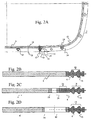
- FIG. 2A shows a plan view of a carrier frame seal 2 according to the invention, in which the recesses 10 for the fastening elements are open towards the side of the sealing profile 6, rings or ring elements 24 being inserted into the recesses.
- FIG. 2B is the cut of FIG. 2A englang the line B shown, with the support frame 4 and the sealing profile 6 with the, two sealing lips 16 comprehensive sealing area 18. Die FIG. 2B corresponds to the Figure 1A , without the passage opening.
- FIG. 2A Furthermore, a section line C is shown, which merely intersects the recess 10.
- the Figure 2C or the section C shows a flat gate through the provided with a ring 24 recess 10. Due to the flat section 5, the ring appears wider and the free space of the ring appears smaller.
- the sealing profile 6 includes there the same 18 with the same two side by side extending sealing lips 16, which extend at the same distance from each other.
- FIG. 2D clearly shows how narrow the bridge can be performed using the ring element.
- a conventional punched web which would achieve the same gain on the side of the sealing profile 6, could not be produced.
- such a bridge can not be produced by conventional and inexpensive punching methods, since its height in the punching direction is greater than or twice as large as its width.
- Such a thin web of the material of the support frame can be achieved only with other expensive manufacturing processes such as laser cutting, photoetching or spark erosion. It can also be seen that such a thin web of the material of the support frame 4 can not withstand the pressures in an injection molding machine, which is why it is to be feared that this will be damaged during molding of the sealing profile of the web.
- the ring in Figure 2C can be made of a stronger material than the material of the support frame, which is why the ring can withstand the forces acting on the injection molding of the sealing profile without deforming.
- a ring of stronger material can also accommodate bolting forces acting on the built-in seal in a region of less width.
- FIG. 3A illustrates a plan view of another embodiment according to the invention of a carrier frame seal 2 FIG. 3A the recesses 10 also extend to the edge. In the recesses rings or ring elements 24 are additionally inserted, which need not be prepared by punching.
- the FIGS. 3B to 3D each represent sectional views taken along lines B, C and D of FIG FIG. 3A in this FIG. 3A It can be seen that the sealing profile 6 is wider in the areas which are remote from the recesses, as directly to the recesses 10.
- the sealing profile is narrower in the region of the recesses and is brought together by two sealing lips 16 to a sealing lip 20 ,
- the section B or the FIG. 3B corresponds to the FIGS. 2A and 1A ,
- the sealing profile 6 comprises a sealing region 18 with two sealing lips 16 extending side by side.
- the section C or the FIG. 3C shows a flat gate through the provided with a ring 24 recess 10. Due to the flat section 5, the ring appears wider and the recess 10 appears smaller.
- the sealing profile 6 likewise comprises a sealing region 18 with two sealing lips 16 running side by side, which, however, are brought closer together.
- the section D or the Figure 3D shows a section straight through the center of the recess 10 and through the ring 24. By the straight cut the small radial thickness of the ring 24 can be seen, which is smaller than the axial extent of the ring 24.
- the sealing profile 6 also includes there a sealing area with only a single wider sealing lip 20, resulting from the converging sealing lips 16.
- This embodiment of the invention is based on the fact that the area of the critical screw connection opening or recess 10 is punched free and in this area an additional ring-shaped element or a ring 24 is inserted. It is also possible to use a plurality of annular elements in each case at several or all screwed openings. The annular elements 24 take over the function of Bolt opening bypass on the support plate 4, whereby the recess is completely closed inwardly to the screw 10. The actual support frame 4 does not bypass the recess 10 on the side to the elastomer sealing profile 6, since this area is formed in each case by the additional element or the additional ring 24.
- the actual support frame 4 always has an opening to the inside, in which then the ring is located, which takes on the task of the support frame at this point to surround the screw hole closed.
- the solution may be such that the ring 24 bears only minimally on the support frame side 4 up to an embodiment in which the ring element is still somewhat enclosed from both sides.
- the ring element is surrounded by the support frame more than half, and can then be particularly easily in the support frame positioned or pre-assembled with a press fit (or be clamped).
- the rings 24 could theoretically but also separately be used without direct connection to the support plate only in the tool, for example on pins, and be connected during the injection process with the support frame by elastomer.
- the annular elements 24 can be manufactured separately, which is why other manufacturing methods can be used as punching.
- the typical manufacturing limits of the stamping process can be circumvented.
- the manufacturing process is extrusion or machining. Likewise, drawing is possible as a production method. It is even possible to bend the ring elements of square wire, in use should point the seam in the direction of the support frame and not in the direction of the elastomer sealing profile.
- the ring elements can be manufactured cost-optimized with sufficient manufacturing accuracy. These elements can be manufactured with great accuracy. It is even intended to produce the ring elements by metal injection molding quickly and easily.
- a bypass with a square cross section is already at the limit of what can be produced inexpensively with a stamping method.
- Such a bypass requires a minimum width of 2 mm and would already have the disadvantages described above.
- Typical internal diameters are approximately 6.8 to 7mm for M6 screws, which are commonly used in such flange fittings.
- the production of a Ring element in the turning process with an inner diameter of about 7mm and a height of 2mm with a width of 2mm or even less no great challenge.
- annular elements can be made of a different material than the rest of the support frame. It is thus possible to produce an aluminum support frame 4 with annular elements 24 made of steel or brass in order to reduce the dimensions of the support frame seal even more with the same strength can.
- the annular elements can either be pre-assembled and connected as a unit to the support frame or separately inserted only in the injection mold. Depending on the combination of materials, pressing, gluing, welding are suitable for pre-assembly.
- overmolded carrier frame seals In the area of overmolded carrier frame seals, i. in seals in which a thin support plate is integrated in an elastomeric profile, there are already different embodiments with incorporated rings.
- the rings serve as spacers for sealing gap limitation.
- a thin carrier plate usually steel is used in which the function of spacers is effected by pressed or inserted rings.
- the support frame is in this case completely encapsulated and the rings are usually arranged centrally in the support frame.
- the ring or the ring member is used, which has the same axial dimension or thickness as the support frame.
- overmolded carrier frame seals can not be readily compared with carrier frame seals in which the sealing profile is molded onto only one end face.
- the present invention allows in one embodiment to achieve a minimal space and a smaller space than can be represented with all known solutions. It is now possible with the present invention to significantly reduce the dimensions of a carrier frame seal.
- the present invention permits the use of different combinations of materials to further optimize the support frame seal in terms of manufacturing cost, weight, dimensions, and packaging space.
- There are variants with different heights of the ring elements conceivable, but conventionally only ring elements are used whose dimensions correspond to the height of the support plate.
- the rings may have some overhang to be deformed to the optimum height when the tool is closed, and to securely seat the tool in place to avoid elastomer overflows.
- the properties of the carrier frame seal can be further influenced.
- the use of steel rings can increase the strength in the area of the screw eyes, and larger screw forces can be transmitted.
- the width of the ring by having the ring, for example, an oval outer shape and a round inner shape.
- the forces that are applied by the screws on the ring and especially on the sealing flange can be better distributed to prevent the ring can dig into the flange of an aluminum component.
Description
Die vorliegende Erfindung betrifft Trägerrahmendichtungen, wie sie für Gehäuseteile mit Dichtflächen wie Deckel oder Hauben verwendet werden, die an anderen Maschinenteilen befestigt werden.The present invention relates to girder seals, as used for housing parts with sealing surfaces such as covers or hoods, which are attached to other machine parts.
Die vorliegende Erfindung bezieht sich vorzugsweise auf den Einsatz bei Trägerrahmendichtungen. Die vorliegende Erfindung betrifft dabei insbesondere eine Bauform, bei der ein Dichtprofil aus Elastomer stumpf an der Stirnseite eines Trägerrahmens anvulkanisiert ist. Diese Ausführungsform hat den Vorteil, dass man einen Trägerrahmen wie einen Aluminiumträgerrahmen einmal als Trägerrahmen für das Dichtprofil benutzt und dieser auch andererseits als Wegbegrenzer bzw. Verpressungsbegrenzer für die Elastomerdichtung dient und zusätzlich die Verschraubungskräfte aufnimmt. Der Trägerrahmen wirkt hier als Verpressungsbegrenzer, so dass die Dichtung im Kraftnebenschluss liegt. Idealerweise hat der Flansch, auf dem die Dichtung montiert werden soll, eine ausreichende Breite, d.h. es ist genug Raum sowohl für das Dichtprofil als auch ausreichend Auflagefläche für den Trägerrahmen vorhanden. Die Trägerrahmen für solche Dichtungen werden fast ausschließlich durch Stanzen hergestellt, da dies die kostengünstigste Möglichkeit der Herstellung ist.The present invention preferably relates to use with carrier frame gaskets. The present invention relates in particular to a design in which a sealing profile made of elastomer is vulcanized on the end face of a support frame. This embodiment has the advantage that one uses a support frame such as an aluminum support frame once as a support frame for the sealing profile and this also serves as Wegbegrenzer or Verpressungsbegrenzer for the elastomeric seal and additionally absorbs the Verschraubungskräfte. The support frame acts here as Verpressungsbegrenzer, so that the seal is in the force shunt. Ideally, the flange on which the gasket is to be mounted has a sufficient width, i. There is enough room for both the sealing profile and sufficient support surface for the support frame available. The support frames for such seals are made almost exclusively by stamping, as this is the least expensive option to manufacture.
Aufgrund stetig steigender Anforderungen an Bauraumreduzierung, Gewichtsreduzierung, etc. wurden die Flanschflächen für die Dichtungen stetig bis an die Grenzen der Herstellungsmasse von Trägerrahmendichtungen reduziert. Inzwischen sind an bestimmten Stellen oder auch bei gesamten Bauteilen die Grenzen erreicht, sodass eine sinnvolle Herstellung und auch Funktion der Dichtungen in Frage zu stellen ist.Due to steadily increasing requirements for space reduction, weight reduction, etc., the flange surfaces for the seals have been steadily reduced to the limits of the manufacturing mass of carrier frame seals. In the meantime, the limits have been reached at certain points or even in the case of entire components, so that a sensible production and also function of the seals must be called into question.
Kritische Stellen einer Trägerrahmendichtung in Bezug auf die Flanschbreiten sind im Allgemeinen die Bereiche um Verschraubungen herum. Der Grund hierfür liegt darin, dass abgesehen von der Öffnung im Trägerrahmen, durch den die Schraube geführt wird, der Trägerrahmen innen und außen an der Verschraubungsöffnung vorbeigeführt werden muss, damit sich wiederum eine geschlossene Bohrung ergibt. Bekannte Sonderlösungen werden im Stand der Technik angegeben.Critical locations of a girder seal relative to the flange widths are generally the areas around glands. The reason for this is that, apart from the opening in the support frame through which the screw is guided, the support frame must be guided past inside and outside of the screw, so that in turn results in a closed bore. Known special solutions are specified in the prior art.
Oftmals ist von diesen kritischen Stellen nicht der ganze Trägerrahmen betroffen, sondern evtl. existiert nur eine Verschraubungsöffnung, bei der dieses Problem auftritt. Es können aber auch der komplette Trägerrahmen und somit alle Verschraubungspunkte betroffen sein.Often, these critical points do not affect the entire support frame, but possibly only a threaded opening exists at which this problem occurs. But it can also be the entire support frame and thus all screwing be affected.
Der Stand der Technik (Standardlösung) und auch die einfachste Umsetzung dieser Bereiche in eine Dichtungslösung sind gegeben, wenn die Flanschfläche beider Bauteile in allen Bereichen genügend Breite und Überdeckung zur Verfügung stellt. In diesen Fällen ist es nicht notwendig, an die Herstellbarkeitslimits der Trägerrahmen zu gehen und die Umfahrungen im Bereich der Verschraubungsöffnungen besitzen nach außen wie auch innen eine ausreichende Trägerrahmenbreite. Idealerweise bietet die Flanschfläche auch genügend Platz, damit zwei Dichtlippen um den Verschraubungsbereich herumgeführt werden können, die dann innerhalb aller Toleranzlagen sicher auf den beiden Flanschseiten aufliegen, wobei die Dichtlippen mit beiden Flanschen in sicherem Kontakt stehen.The state of the art (standard solution) and also the simplest implementation of these areas in a sealing solution are given if the flange surface of both components provides sufficient width and coverage in all areas. In these cases, it is not necessary to go to the manufacturability limits of the support frame and the bypasses in the region of the screw holes have both outside and inside a sufficient support frame width. Ideally, the flange surface also provides sufficient space to allow two sealing lips to be guided around the threaded connection area, which then rest securely on the two flange sides within all tolerance positions, with the sealing lips in secure contact with both flanges.
Für eine Umfahrung im Bereich der Schraubdurchgänge, aber auch für andere schmale Bereiche liegt die minimale Stegbreite, die sich sinnvoll durch Stanzen herstellen lässt, etwa bei einem Verhältnis von 2 zu 1. Das bedeutet, dass ein Steg mindestens doppelt so breit ausgeführt werden muss, wie die Dicke des Bleches, in den der Steg gestanzt wird. Ist das Trägerblech beispielsweise 1 ,5mm dick, muss der Steg ca. 3mm breit sein, damit er noch gut im Stanzwerkzeug geklemmt und ausgestanzt werden kann, ohne dass größere Verformungen des Stegs auftreten. Bei vielen Teilen wird diese Grenze inzwischen unterschritten und die im Folgenden beschriebenen Nachteile in Kauf genommen.For a bypass in the area of the screw passages, but also for other narrow areas, the minimum web width, which can be sensibly produced by punching, is approximately at a ratio of 2 to 1. This means that a web must be made at least twice as wide like the thickness of the sheet into which the web is punched. If the carrier sheet is, for example, 1.5 mm thick, the web must be about 3 mm wide, so that it can still be clamped and punched well in the punching tool without major deformations of the web occurring. In many parts, this limit is now undercut and taken into account the disadvantages described below.
Eine weitere Reduzierung der Umfahrungsbreite wäre notwendig, um überhaupt eine Lösung für diese Problemstellen zur Verfügung zu haben. Eine schmalere Umfahrung der Schraubenöffnung am Trägerrahmen kann nur unter das sinnvolle Maß reduziert werden, wenn andere Nachteile in Kauf genommen werden. Wird die Breite des Stegs bis hin zu einem quadratischer Querschnitt (z.B. Trägerblechdicke 1,5mm und Stegbreite 1,5mm) verringert, wird der Steg beim Stanzen deformiert, und es bilden sich durch das Stanzen bedingte Einzüge und der Steg kann sich auch verdrehen. Das Ergebnis aus der Stanzung ist in dem Bereich dann nicht mehr eindeutig geometrisch vorhersagbar. Abgesehen von der Verformung wird durch diese dünnen Stege auch die Steifigkeit des Trägerrahmens stark beeinträchtigt, was zu gravierenden Nachteilen beim Anspritzen der Elastomerdichtung führen kann, da der Spritzdruck bei der Fertigung den Steg verbiegen kann. Setzt man Stifte im Werkzeug an den Bohrungen zur Begrenzung der Verformung des Rahmens ein, können diese verklemmen und bei der Entnahme aus der Form wieder um die dünnen Stege verbiegen.A further reduction of the range of travel would be necessary in order to have a solution for these problem areas at all. A narrower deflection of the screw opening on the support frame can only be reduced below the reasonable level, if other disadvantages are accepted. If the width of the web down to a square cross-section (eg support sheet thickness 1.5mm and web width 1.5mm) is reduced, the web is deformed during punching, and it formed by the punching induced indentations and the web can also rotate. The result of the punching in the area is then no longer clearly geometrically predictable. Apart from the deformation, the stiffness of the support frame is greatly affected by these thin webs, which can lead to serious disadvantages when molding the elastomeric seal, since the injection pressure during manufacture can bend the web. Inserting pins in the tool at the holes to limit the deformation of the frame, they can jam and when removing from the mold again around the thin webs bend.
Ein weiterer gravierender Nachteil von sehr schmalen Stegen besteht in den Stanzeinzügen. Ein Stanzeinzug ist eine Verformung der Blechkante an einer Stanzlinie. Stanzeinzüge verhindern, dass der Trägerrahmen im Spritzwerkzeug optimal geklemmt werden kann, wodurch sich Überspritzungen von Elastomermaterial auf den Trägerrahmen, und in die Schraubenlöcher ergeben können, was nicht akzeptabel ist.Another serious disadvantage of very narrow webs is the punching feeders. A punch is a deformation of the sheet edge on a punching line. Punch feeds prevent the carrier frame from being optimally clamped in the injection mold, which may result in over-molding of elastomeric material on the carrier frame and in the screw holes, which is unacceptable.
Ohne eine sichere Trennung der Elastomerbereiche und der Metallbereiche ist eine kostengünstige Fertigung, aufgrund von notwendigen Nacharbeiten nicht sinnvoll umsetzbar.Without a secure separation of the Elastomerbereiche and the metal areas is a cost-effective production, due to necessary rework not feasible.
Ein weiteres Problem besteht darin, dass durch die unzureichende Abprägung das Elastomermaterial in die Bohrung laufen kann, die dann aufwändig von Hand wieder gesäubert werden muss.Another problem is that due to the insufficient impression, the elastomer material can run into the bore, which then has to be laboriously cleaned again by hand.
Herkömmliche Trägerrahmendichtungen sind beispielsweise aus der
Bisher bestehen keine Möglichkeiten, kleinere Flanschbreiten mit einer Umfahrung des Trägerrahmens darzustellen. Es besteht bisher nur die Möglichkeit, das Design der Bauteile, die den Dichtflansch bilden, zu verändern, um die Flanschbreite zu erhöhen, dass die bekannte Bauform einer Trägerrahmendichtung eingesetzt werden kann.So far, there are no possibilities to represent smaller flange widths with a bypass of the support frame. So far, there is only the possibility to change the design of the components that form the sealing flange in order to increase the flange width that the known design of a support frame seal can be used.
Es ist also wünschenswert, Möglichkeit zur Verfügung zu stellen, bei der die Flanschbreiten reduziert werden können, d.h. also speziell die Breite der Trägerrahmendichtung im Bereich einer Umfahrung auf der Elastomerseite verringert werden kann, ohne dass die oben beschriebenen Nachteile auftreten.It is thus desirable to provide a way in which the flange widths can be reduced, i. Thus, in particular the width of the carrier frame seal in the region of a bypass on the elastomer side can be reduced without the disadvantages described above occur.
Es besteht eine allgemeine Designvorgabe, Material bei der Herstellung einzusparen. Weiterhin besteht ein Bedarf, die Dichteigenschaften einer Trägerrahmendichtung zu verbessern. Schließlich besteht ebenfalls ein Bedarf, den Platzbedarf für Trägerrahmendichtungen zu verringern. Diese Forderung ergibt sich auch aus der Vorgabe, die abzudichtenden Bauteile möglichst leicht zu gestalten.There is a general design requirement to save material during manufacture. Furthermore, there is a need to improve the sealing properties of a carrier frame seal. Finally, there is also a need to reduce the footprint for girder seals. This requirement also arises from the requirement to make the components to be sealed as easy as possible.
Gemäß einem ersten Aspekt der vorliegenden Erfindung wird eine Trägerrahmendichtung mit verringertem Platzbedarf bereitgestellt. Die Trägerrahmendichtung umfasst einen Trägerrahmen und ein Dichtprofil aus einem Elastomermaterial, das stumpf an einer Stirnseite eines Trägerrahmens anvulkanisiert ist. Der Trägerrahmen weist weiter Aussparungen für Befestigungselemente auf. An mindestens einer Aussparung ist der Trägerrahmen an der Seite, an dem das Dichtprofil anvulkanisiert ist unterbrochen, und verläuft nur auf der dem Dichtprofil gegenüberliegenden Seite der mindestens einen Ausnehmung. Weiterhin ist der Trägerrahmen an der mindestens einen Aussparung mit einem Ring bzw. mit einem Ringelement versehen.According to a first aspect of the present invention, a carrier frame seal is provided with a reduced footprint. The carrier frame seal comprises a support frame and a sealing profile made of an elastomeric material which is dull on one end face a support frame is vulcanized. The support frame further has recesses for fastening elements. At at least one recess of the support frame on the side at which the sealing profile is vulcanized is interrupted, and extends only on the opposite side of the sealing profile of the at least one recess. Furthermore, the support frame is provided on the at least one recess with a ring or with a ring element.
Der Ring bzw. das Ringelement ist dazu bestimmt um ein Befestigungselement zu umgeben, das durch die Ausnehmung verlaufen soll. Der Ring bzw. das Ringelement liegt dabei in der Ebene des Trägerrahmens.The ring or the ring element is intended to surround a fastener which is to pass through the recess. The ring or the ring element lies in the plane of the support frame.
In dieser Ausführungsform ist das Durchgangsloch für Befestigungsschrauben durch den Trägerrahmen zur Seite der Elastomerdichtung hin offen. Das Durchgangsloch für Befestigungsschrauben in dem Trägerrahmen wurde in dieser Ausführungsform zu einer halboffenen Ausnehmung erweitert. Die offene Seite der Ausnehmung in dem Trägerrahmen wird dabei durch den Ring bzw. das Ringelement geschlossen.In this embodiment, the through hole for fixing screws is open through the support frame toward the side of the elastomeric seal. The through hole for fastening screws in the support frame has been expanded in this embodiment to a semi-open recess. The open side of the recess in the support frame is closed by the ring or the ring member.
Das anvulkanisierte Elastomer schließt dabei eventuelle Übergänge zwischen Ring bzw. dem Ringelement und dem Dichtprofil.The vulcanized elastomer closes any transitions between the ring or the ring element and the sealing profile.
Bei dieser Ausführungsfonn wird auf eine vollständige Umfahrung der Verschraubungsöffnung durch den Trägerrahmen selbst auf der Seite verzichtet, an der das Dichtprofil angeordnet ist. Die fehlende Umfahrung wird dabei durch den Ring bzw. das Ringelement bereitgestellt. Durch diese Form kann ausreichend stabile Umfahrung des Verschraubungsbereiches bei gleichzeitig verringertem Platzbedarf erreicht werden. Gleichzeitig können die gravierenden Nachteile in der Fertigung wie den vorstehend beschriebenen Stanzeinzug und die Verformung der dünnen Umfahrungsbereiche vermieden werden.In this Ausführungsfonn is waived a complete bypass of the screw through the support frame itself on the side on which the sealing profile is arranged. The missing bypass is provided by the ring or the ring element. This form can be sufficiently stable bypassing the Verschraubungsbereiches achieved while reducing space requirements. At the same time, the serious disadvantages in the production, such as the above-described stamping mechanism and the deformation of the thin bypass areas, can be avoided.
In einer zusätzlichen beispielhaften Ausführungsform weist der Ring eine Wanddicke auf, die kleiner ist als eine Breite eines Steges, der in den Trägerrahmen gestanzt werden kann, ohne dass sich das Material des Trägerrahmens verzieht, Einzüge entstehen oder der verbleibende Steg sich beim Ausstanzen verdrehen kann. Der Ring muss nicht durch ausstanzen hergestellt sein, und kann daher einen Querschnitt aufweisen, die mit stanzen nicht zu erreichen ist. Die Wandstärke des Rings in Radialrichtung kann kleiner sein wie die Dicke des Rings in Axialrichtung. Die Wandstärke des Rings in Radialrichtung kann weniger als halb so klein sein wie die Dicke des Rings in Axialrichtung.In an additional exemplary embodiment, the ring has a wall thickness that is less than a width of a ridge that can be stamped into the carrier frame without warping the material of the carrier frame, indenting, or allowing the remaining ridge to twist during punching. The ring need not be made by punching, and therefore may have a cross section that can not be achieved with punching. The wall thickness of the ring in the radial direction may be smaller than the thickness of the ring in the axial direction. The wall thickness of the ring in the radial direction may be less than half as small as the thickness of the ring in the axial direction.
In einer anderen zusätzlichen Ausführungsform der Trägerrahmendichtung weist ein Material aus dem Ring gefertigt ist eine höhere Festigkeit auf, als ein Material aus dem der Trägerrahmen gefertigt ist. Damit kann auch erreicht werden, dass sich der Ring im Betrieb nicht verbiegt. Es kann ebenfalls verhindert werden, dass der Ring beim Anspritzen/Vulkanisieren des Dichtprofils der Ring verbogen oder zerstört wird. Ein Ring aus festem Material gestattet es ebenfalls beim Anspritzen/Vulkanisieren des Dichtprofils sicherzustellen, dass kein Elastomermaterial in den Ring bzw. in eine Schraubendurchführung bzw. die Ausnehmung läuft.In another additional embodiment of the carrier frame seal, a material made from the ring has a higher strength than a material from which the carrier frame is made. This can also be achieved that the ring does not bend during operation. It can also be prevented that the ring is bent or destroyed during injection / vulcanization of the sealing profile of the ring. A ring of solid material also makes it possible during injection / vulcanization of the sealing profile to ensure that no elastomer material runs into the ring or into a screw leadthrough or the recess.
In einer beispielhaften Ausführungsform wird mindestens eine weitere der Aussparungen von dem Dichtprofil umfahren, wobei das Dichtprofil im Bereich mindestens einer Umfahrung in der Breite verringert ist. Diese Ausführungsform betrifft eine Dichtung mit einer offenen oder mit einem Ring versehen Ausnehmung die von einem Dichtprofil umfahren wird, das in seiner Breite verringert ist. Durch diese Konstruktion kann die Breite der Trägerrahmendichtung an einer Umfahrung einer Befestigungsöffnung weiter stark verringert werden, bzw. der Platzbedarf der Trägerrahmendichtung wird im Bereich einer Verschraubung bzw. einer Befestigungsöffnung maximal verringert.In an exemplary embodiment, at least one further of the recesses is bypassed by the sealing profile, wherein the sealing profile is reduced in the region of at least one deflection in the width. This embodiment relates to a seal with an open or ring-shaped recess which is bypassed by a sealing profile which is reduced in width. By virtue of this construction, the width of the carrier frame seal on a bypass of a fastening opening can be further greatly reduced, or the space requirement of the carrier frame seal is maximally reduced in the region of a screw connection or a fastening opening.
In einer weiteren zusätzlichen Ausführungsform der Trägerrahmendichtung weist das Dichtprofil in dem Bereich der mindestens einen Umfahrung bzw. der einseitig offenen Ausnehmung bzw. des Rings eine Dichtlippe auf, während das Dichtprofil in Bereichen außerhalb der mindestens einen Umfahrung der einseitig offenen Ausnehmung bzw. des Rings zwei Dichtlippen aufweist, die nebeneinander verlaufen.In a further additional embodiment of the carrier frame seal, the sealing profile has a sealing lip in the region of the at least one bypass or the recess or ring open on one side, whereas the sealing profile in regions outside the at least one bypass of the recess or ring open on one side Having sealing lips which run side by side.
In einer weiteren Ausführungsform der Trägerrahmendichtung weist das Dichtprofil in dem Bereich der mindestens einen Umfahrung eine Dichtlippe auf, während das Dichtprofil in Bereichen außerhalb der mindestens einen Umfahrung zwei Dichtlippen aufweist, die nebeneinander verlaufen.In a further embodiment of the carrier frame seal, the sealing profile has a sealing lip in the region of the at least one bypass, while the sealing profile has two sealing lips in regions outside the at least one bypass which run next to one another.
Dies lässt sich auch auf Dichtprofile mit mehr als zwei, d.h. drei oder mehreren Dichtlippen in Bereichen außerhalb der mindestens einen Umfahrung umsetzen. Damit sind auch wenn im restlichen Flanschbereich zwei oder mehrere Dichtlippen vorhanden sind, im Bereich der Schraubenaugen die Anzahl der Dichtlippen auf eine verringert. Dabei können zwei oder mehrere Dichtlippen im Bereich eine Umfahrung zu einer einzigen Dichtlippe zusammengeführt werden, die nach der Umfahrung wieder in zwei Dichtlippen auseinanderläuft. Das Zusammenführen der Dichtlippen zu einer einzigen im Bereich der Verschraubung erscheit aus technisch vertretbar, da an dieser Stelle minimale Toleranzen bei optimaler Verpressungskraft vorliegen.This can also be implemented on sealing profiles with more than two, ie three or more sealing lips in areas outside the at least one bypass. Thus, even if two or more sealing lips are present in the remaining flange, in the region of the screw eyes, the number of sealing lips reduced to one. In this case, two or more sealing lips in the area around a bypass to a single sealing lip can be merged, which diverge after passing around again in two sealing lips. Merging the sealing lips into a single in the area of Fastening protrudes from technically justifiable, since at this point minimal tolerances with optimal compression force are present.
In einer weiteren beispielhaften Ausführungsform der Trägerrahmendichtung ist die eine Dichtlippe breiter ausgeführt als jede der beiden nebeneinander verlaufenden zwei oder mehreren Dichtlippen.In a further exemplary embodiment of the carrier frame seal, the one sealing lip is made wider than each of the two adjacent two or more sealing lips.
Es ist ebenfalls vorgesehen die einzelne Dichtlippe höher auszuführen als jede der beiden nebeneinander verlaufenden zwei oder mehreren Dichtlippen. Dabei kann einer höhere Verpressung der einzelnen Dichtlippe und eine höhere Dichtwirkung im Bereich der Verschraubung der Bauteile erreicht werden.It is also envisaged to carry out the single sealing lip higher than each of the two adjacent two or more sealing lips. In this case, a higher compression of the individual sealing lip and a higher sealing effect in the region of the screw connection of the components can be achieved.
Es ist vorgesehen, dass der mindestens eine Ring außen nicht rund ist. Eine an der Außenseite eckige oder ovale Form des Rings kann dazu beitragen den Ring besser in der Trägerlage zu fixieren. Ein an der Außenseite ein- oder zweiseitig abgeflachter bzw. ovaler Ring kann zudem den auf ihn ausgeübten Druck durch die Verschraubung oder beim Aufbringen der Elastomers besser aufnehmen bzw. übertragen.It is envisaged that the at least one ring is not round outside. A square on the outside or oval shape of the ring can help fix the ring better in the carrier layer. In addition, a ring flattened on the outside or two-sided or oval ring can better absorb or transmit the pressure exerted on it by the screw connection or when applying the elastomer.
Es ist ebenfalls vorgesehen einen nicht geschlossenen Ring zu verwenden. der Ring muss auf der Seite, die dem Dichtprofil gegenüber liegt nicht geschossen sein, da die Verschraubungskräfte bereits durch den dort angeordneten Trägerrahmen aufgenommen werden können. Bei einer geeigneten Verbindung zwischen Trägerrahmen und Ring bzw. Ringelement kann ebenfalls kein Elastomer durch den nicht-geschlossenen Bereich des Rings eintreten, das dieser Bereich durch den Trägerrahmen abgedeckt ist. Diese Ausführung gestattet den Einsatz von gewickelten Ringelementen, was deren Herstellungskosten für die Ringelemente drastisch senkt.It is also envisaged to use a non-closed ring. the ring must not be shot on the side opposite the sealing profile, since the screwing forces can already be absorbed by the support frame arranged there. With a suitable connection between the support frame and ring or ring element also no elastomer can enter through the non-closed region of the ring, which is covered by this area of the support frame. This design allows the use of wound ring elements, which drastically reduces their manufacturing costs for the ring elements.
Gemäß einem weiteren Aspekt der der vorliegenden Erfindung wird eine Trägerrahmendichtung mit verringertem Platzbedarf bereitgestellt. Die Trägerrahmendichtung umfasst einen Trägerrahmen und ein Dichtprofil aus einem Elastomermaterial, das stumpf an eine Stirnseite eines Trägerrahmens anvulkanisiert ist. Der Trägerrahmen ist weiter mit Aussparungen für Befestigungselemente versehen, die dem Dichtprofil umfahren werden. Die Breite des Dichtprofils ist dabei im Bereich mindestens einer Umfahrung im Vergleich zu einer Breite des Dichtprofils in einem Bereich ohne Ausnehmung verringert.In accordance with another aspect of the present invention, a carrier frame seal with reduced footprint is provided. The carrier frame seal comprises a carrier frame and a sealing profile made of an elastomeric material, which is vulcanized vulcanized to an end face of a carrier frame. The support frame is further provided with recesses for fasteners, which are bypassed the sealing profile. The width of the sealing profile is reduced in the region of at least one bypass in comparison to a width of the sealing profile in a region without a recess.
Die Ausnehmung können beispielsweise als Durchgangslöcher für Befestigungsschrauben ausgeführt werden.The recess can be carried out, for example, as through holes for fastening screws.
Es wird auf vollständige Umfahrung der Verschraubungsöffnung verzichtet, wobei das Dichtprofil nicht mit seiner vollständigen Breite die Verschraubungsöffnung umfährt. Dies bringt Nachteile bei der Abdichtung mit sich wobei durch eine geeignete Wahl der Form des Dichtprofils eine ausreichende stabile Umfahrung des Verschraubungsbereiches erreicht werden kann einen hinreichenden Platzvorteil bietet.It is dispensed with complete bypass of the screw, wherein the sealing profile does not bypass with its full width the screw hole. This brings disadvantages in the sealing with a sufficient stable bypassing the Verschraubungsbereiches can be achieved by a suitable choice of the shape of the sealing profile can provide sufficient space advantage.
Dies lässt sich wie vorstehend beschrieben auch auf Dichtprofile mit mehr als zwei, d.h. drei oder mehreren Dichtlippen in Bereichen außerhalb der mindestens einen Umfahrung anwenden.This can also be applied to sealing profiles with more than two, as described above. Apply three or more sealing lips in areas outside the at least one bypass.
In einer weiteren beispielhaften Ausführungsform der Trägerrahmendichtung ist die eine Dichtlippe breiter ausgeführt als jede der beiden nebeneinander verlaufenden zwei oder mehreren Dichtlippen. Es ist ebenfalls vorgesehen die einzelne Dichtlippe höher auszuführen als jede der beiden nebeneinander verlaufenden zwei oder mehreren Dichtlippen. Dabei kann einer höhere Verpressung der einzelnen Dichtlippe und eine höhere Dichtwirkung im Bereich der Verschraubung der Bauteile erreicht werden.In a further exemplary embodiment of the carrier frame seal, the one sealing lip is made wider than each of the two adjacent two or more sealing lips. It is also envisaged to carry out the single sealing lip higher than each of the two adjacent two or more sealing lips. In this case, a higher compression of the individual sealing lip and a higher sealing effect in the region of the screw connection of the components can be achieved.
In einer weiteren beispielhaften Ausführungsform übersteigt eine Dicke des Elastomers mit dem der unterbrochene Bereich des Trägerrahmens an der mindestens einen Aussparung mit Elastomer gefüllt ist, die eine Dicke des Trägerrahmens in diesem Bereich. Damit wird in dem Bereich in dem das Elastomer das Material des Trägerrahmens ersetzt eine höhere Verpressung des Elastomers erreicht, sodass verhindert werden kann, dass sich der Dichtbereich zu leicht in Richtung des Befestigungselements bewegen kann, und so eventuell beschädigt werden kann. Damit wird das Elastomer, das das Material des Trägerrahmens ersetzt, vorgespannt, um höheren Belastungen zu widerstehen.In another exemplary embodiment, a thickness of the elastomer with which the discontinuous region of the support frame is filled with elastomer at the at least one recess exceeds a thickness of the support frame in that region. Thus, in the region in which the elastomer replaces the material of the support frame, a higher compression of the elastomer is achieved, so that it can be prevented that the sealing region can move too easily in the direction of the fastening element, and thus possibly be damaged. This biases the elastomer replacing the support frame material to withstand higher loads.
In einer weiteren beispielhaften Ausführungsform der Trägerrahmendichtung ist die eine Dichtlippe breiter ausgeführt als jede der beiden nebeneinander verlaufenden zwei oder mehreren Dichtlippen.In a further exemplary embodiment of the carrier frame seal, the one sealing lip is made wider than each of the two adjacent two or more sealing lips.
Es ist ebenfalls vorgesehen die einzelne Dichtlippe höher auszuführen als jede der beiden nebeneinander verlaufenden zwei oder mehreren Dichtlippen. Dabei kann einer höhere Verpressung der einzelnen Dichtlippe und eine höhere Dichtwirkung im Bereich der Verschraubung der Bauteile erreicht werden.It is also envisaged to carry out the single sealing lip higher than each of the two adjacent two or more sealing lips. In this case, a higher compression of the individual sealing lip and a higher sealing effect in the region of the screw connection of the components can be achieved.
In einer weiteren beispielhaften Ausführungsform ist der Trägerrahmen der Trägerrahmendichtung durch Ausstanzen aus einem Blech hergestellt.In a further exemplary embodiment, the carrier frame of the carrier frame seal is produced by punching out of a metal sheet.
Es ist bevorzugt, dass der Ring (die Ringe) eine andere Höhe hat (haben) als der Trägerrahmen bzw der Ring (die Ringe) mit dem Trägerrahmen im Spritzwerkzeug verbunden werden kann (können), zB mit Elastomer. Alternativ kann der Ring (die Ringe) mit dem Trägerrahmen schon vor dem Spritzprozess verbunden werden, zB durch Einclipsen, Einpressen, Einkleben und ist somit mit dem Trägerrahmen verbunden, wobei der Rahmen "einstückig" ins Spritzwerkzeug eingelegt werden kann.It is preferred that the ring (s) have (have) a different height than the support frame or ring (s) to be connected to the support frame in the injection molding tool, eg with elastomer. Alternatively, the ring (the rings) can be connected to the support frame before the injection process, for example by clipping, pressing, gluing and is thus connected to the support frame, the frame can be "integrally" inserted into the injection mold.
In den Figuren sind bevorzugte Ausführungsformen der vorliegenden Erfindung dargestellt.
-
Figur 1 und 1A zeigten verschiedene Ansichten einer herkömmlichen Trägerrahmendichtung. -
Figuren 2A bis 2D stellen Ansichten stellt einer erfindungsgemäßen Trägerahmendichtung dar. -
Figuren 3A bis 3D stellen jeweils Detailansichten einer anderen erfindungsgemäßen Trägerrahmendichtung dar.
-
FIGS. 1 and 1A showed different views of a conventional carrier frame seal. -
FIGS. 2A to 2D represent views represents a carrier seal according to the invention. -
FIGS. 3A to 3D each represent detailed views of another carrier frame seal according to the invention.
Sowohl in den Figuren als auch in den Zeichnungen werden gleiche Bezugszeichen verwendet, um gleiche oder ähnliche Elemente und Baugruppen darzustellen. Die Darstellungen können teilweise schematisch oder nicht maßstabsgerecht ausgeführt sein.Both in the figures and in the drawings, like reference numerals are used to represent the same or similar elements and assemblies. The representations may be partially schematic or not to scale.
Es sollte klar sein, dass es nicht möglich ist, die Breite der Umfahrung 12 bei gegebener Dicke beliebig zu verkleinern, sofern der Trägerrahmen durch Stanzen aus einem Blech hergestellt werden soll.It should be clear that it is not possible to arbitrarily reduce the width of the
In
In
Die
In
Der Ring in
Der Schnitt B bzw. die
Der Schnitt C bzw. die
Der Schnitt D bzw. die
Diese erfindungsgemäße Ausführungsform beruht darin, dass der Bereich der kritischen Verschraubungsöffnung bzw. Ausnehmung 10 freigestanzt ist und in diesem Bereich ein zusätzliches ringförmiges Element oder ein Ring 24 eingesetzt ist. Es können auch mehrere ringförmige Elemente jeweils an mehreren oder allen Verschraubungsöffnungen eingesetzt werden. Die ringförmigen Elemente 24 übernehmen die Funktion der Schraubenöffnungsumfahrung am Trägerblech 4, wodurch die Ausnehmung nach innen zur Verschraubungsöffnung 10 vollständig geschlossen ist. Der eigentliche Trägerrahmen 4 umfährt die Ausnehmung 10 auf der Seite zum Elastomer-Dichtprofil 6 nicht, da dieser Bereich jeweils durch das zusätzliche Element bzw. den zusätzlichen Ring 24 gebildet wird. Das bedeutet, dass bei dieser neuartigen Lösung der eigentliche Trägerrahmen 4 immer zur Innenseite hin eine Öffnung aufweist, in der dann der Ring liegt, der an dieser Stelle die Aufgabe des Trägerrahmens übernimmt, die Schraubenöffnung geschlossen zu umgeben. Die Lösung kann so aussehen, dass der Ring 24 nur minimal an der Trägerrahmenseite 4 anliegt bis zu einer Ausführungsform, bei der das Ringelement noch etwas von beiden Seiten her umschlossen ist.This embodiment of the invention is based on the fact that the area of the critical screw connection opening or
Idealerweise wird das Ringelement von dem Trägerrahmen mehr als halb umschlossen, und kann dann besonders einfach in dem Trägerrahmen positioniert bzw. mit einer Presspassung Vormontiert werden (bzw. eingeklemmt werden). Die Ringe 24 könnten theoretisch aber auch separat ohne direkte Verbindung zum Trägerblech erst im Werkzeug beispielsweise auf Stifte eingesetzt werden, und beim Spritzprozess mit dem Trägerrahmen durch Elastomer verbunden werden.Ideally, the ring element is surrounded by the support frame more than half, and can then be particularly easily in the support frame positioned or pre-assembled with a press fit (or be clamped). The
Die ringförmigen Elemente 24 können separat gefertigt werden, weshalb andere Fertigungsverfahren als Stanzen genutzt werden können. Durch den Einsatz der Ringe bzw. ringförmigen Elemente können die typischen Herstellungsgrenzen des Stanzprozesses umgangen werden. Als Herstellungsverfahren bietet sich Fließpressen oder auch die spanende Bearbeitung an. Ebenso ist Ziehen als Herstellungsverfahren möglich. Es ist sogar möglich die Ringelemente aus Vierkantdraht zu biegen, wobei im Einsatz die Nahtstelle in Richtung des Trägerrahmens weisen sollte und nicht in Richtung des Elastomer-Dichtprofils. Die Ringelemente können mit hinreichender Fertigungsgenauigkeit kostenoptimiert hergestellt werden. Diese Elemente können mit sehr großer Genauigkeit gefertigt werden. Es ist sogar vorgesehen, die Ringelemente durch Metall-Spritzguss schnell und einfach herzustellen.The
Im Vergleich zu den notwendigen Umfahrungsbreiten am Trägerblech für eine Standardträgerrahmendicke von 2mm ist bereits eine Umfahrung mit einem quadratischen Querschnitt an der Grenze dessen was mit einem Stanzverfahren kostengünstig hergestellt werden kann. Eine derartige Umfahrung benötigt dabei eine Mindestbreite von ebenfalls 2mm und würde bereits die vorstehend beschriebenen Nachteile aufweisen. Typische Innendurchmesser sind bei M6 Schrauben, die häufig bei solchen Flanschverschraubungen angewendet werden liegen bei ca. 6,8 bis 7mm. Im Vergleich zu den Technischen Herausforderungen einer durch Stanzen hergestellten Umfahrung ist die Herstellung eines Ringelements im Drehprozess mit einem Innendurchmesser von ca. 7mm und einer Höhe von 2mm bei Breite von 2mm oder sogar weniger keine große Herausforderung. Abweichend zur Herstellung im Stanzprozess gibt es hier keinerlei Einzüge, was im Nachhinein beim Anspritzen des Elastomers zu einer optimalen Abprägung im Elastomer Spritzwerkzeug führt und Überspritzungen zuverlässig vermeidet. Würde ein Ring mit 2mm Höhe und einer Ringbreite von 1mm eingesetzt, würde das zu einem Vorteil im Bauraum von 1 mm bedeuten was, bei den momentanen geringen Abmessungen einen erheblichen Platzgewinn darstellt, wohingegen bisherige Fortschnitte lediglich in einem Bereich von einzelnen zehntel oder hundertstel Millimeter möglich waren.In comparison to the necessary clearance widths on the carrier plate for a standard carrier frame thickness of 2 mm, a bypass with a square cross section is already at the limit of what can be produced inexpensively with a stamping method. Such a bypass requires a minimum width of 2 mm and would already have the disadvantages described above. Typical internal diameters are approximately 6.8 to 7mm for M6 screws, which are commonly used in such flange fittings. Compared to the technical challenges of a punched bypass, the production of a Ring element in the turning process with an inner diameter of about 7mm and a height of 2mm with a width of 2mm or even less no great challenge. In contrast to the production in the stamping process, there are no indentations here, which in retrospect leads to an optimum embossing in the elastomer injection molding tool during injection molding of the elastomer and reliably avoids overspray. If a ring with 2mm height and a ring width of 1mm used, this would mean an advantage in the space of 1 mm, which represents a considerable gain in space at the current small dimensions, whereas previous cuts only in a range of single tenths or hundredths of a millimeter possible were.
Ein weiterer Vorteil dieser Erfindung besteht darin, dass die ringförmigen Elemente aus einem anderen Material als der Rest des Trägerrahmens hergestellt werden können. Es ist somit möglich einen Aluminiumträgerrahmen 4 mit ringförmigen Elementen 24 aus Stahl oder Messing herzustellen, um bei gleicher Festigkeit die Abmessungen der Trägerrahmendichtung noch weiter verringern zu können.Another advantage of this invention is that the annular elements can be made of a different material than the rest of the support frame. It is thus possible to produce an aluminum support frame 4 with
Die ringförmigen Elemente können entweder vormontiert werden und als Einheit mit dem Trägerrahmen verbunden werden oder auch separat erst in das Spritzwerkzeug eingelegt werden. Zur Vormontage bieten sich je nach Materialkombination Einpressen, Einkleben, Schweißen an.The annular elements can either be pre-assembled and connected as a unit to the support frame or separately inserted only in the injection mold. Depending on the combination of materials, pressing, gluing, welding are suitable for pre-assembly.
Im Bereich umspritzter Trägerrahmendichtungen, d.h. bei Dichtungen in denen ein dünnes Trägerblech in einem, Elastomerprofil integriert ist, gibt es bereits unterschiedliche Ausführungsformen mit eingearbeiteten Ringen. Bei diesen Systemen dienen die Ringe als Abstandshalter zur Dichtspaltbegrenzung. Bei diesen Systemen wird ein dünnes Trägerblech, meist Stahl verwendet bei dem die Funktion von Abstandshaltern durch eingepresste oder eingelegte Ringe erfolgt. Der Trägerrahmen wird hierbei vollständig umspritzt und die Ringe liegen meist Mittig im Trägerrahmen angeordnet. Im Gegensatz dazu wird in der vorliegenden Erfindung der Ring bzw. das Ringelement verwendet, das die gleiche axiale Abmessung bzw. Dicke wie der Trägerrahmen aufweist. Umspritzte Trägerrahmendichtungen lassen sich jedoch nicht ohne weiteres mit Trägerrahmendichtungen vergleichen bei denen das Dichtprofil nur an einer Stirnseite angespritzt ist.In the area of overmolded carrier frame seals, i. in seals in which a thin support plate is integrated in an elastomeric profile, there are already different embodiments with incorporated rings. In these systems, the rings serve as spacers for sealing gap limitation. In these systems, a thin carrier plate, usually steel is used in which the function of spacers is effected by pressed or inserted rings. The support frame is in this case completely encapsulated and the rings are usually arranged centrally in the support frame. In contrast, in the present invention, the ring or the ring member is used, which has the same axial dimension or thickness as the support frame. However, overmolded carrier frame seals can not be readily compared with carrier frame seals in which the sealing profile is molded onto only one end face.
Im Gegensatz zu den
Die vorliegende Erfindung gestattet es in einer Ausführungsform, einen minimalen Bauraum und einen kleineren Bauraum als mit allen bekannten Lösungen darstellbar ist zu erreichen.
Es ist mit der vorliegenden Erfindung nun möglich, die Abmessungen einer Trägerrahmendichtung erheblich zu verringern.
Die vorliegende Erfindung gestattet den Einsatz unterschiedlicher Materialkombinationen, um die Trägerrahmendichtung weither in Bezug auf Herstellungskosten, Gewicht, Abmessungen sowie Bauraum zu optimieren.
Es sind Varianten mit unterschiedlichen Höhen der Ringelemente denkbar, herkömmlich werden jedoch nur Ringelemente verwendet, deren Abmessungen der Höhe des Trägerblechs entsprechen. Bei extrem kleinen Ringbreiten für minimale Abmessungen können die Ringe etwas Überstand haben, um beim Schließen des Werkzeugs auf die optimale Höhe verformt zu werden, und das Werkzeug an der Stelle sicher abzusichten, damit Elastomerüberläufe vermieden werden können.
Durch den Einsatz unterschiedlicher Materialien können die Eigenschaften der Trägerrahmendichtung weiter beeinflusst werden.
Bei Standardträgerblechen aus Aluminium kann z.B. durch den Einsatz von Stahlringen die Festigkeit im Bereich der Schraubenaugen erhöht werden und es können größere Schraubenkräfte übertragen werden.The present invention allows in one embodiment to achieve a minimal space and a smaller space than can be represented with all known solutions.
It is now possible with the present invention to significantly reduce the dimensions of a carrier frame seal.
The present invention permits the use of different combinations of materials to further optimize the support frame seal in terms of manufacturing cost, weight, dimensions, and packaging space.
There are variants with different heights of the ring elements conceivable, but conventionally only ring elements are used whose dimensions correspond to the height of the support plate. For extremely small ring widths for minimum dimensions, the rings may have some overhang to be deformed to the optimum height when the tool is closed, and to securely seat the tool in place to avoid elastomer overflows.
By using different materials, the properties of the carrier frame seal can be further influenced.
In the case of standard aluminum carrier plates, for example, the use of steel rings can increase the strength in the area of the screw eyes, and larger screw forces can be transmitted.
Es ist ebenfalls vorgesehen die Breite des Rings zu optimieren, indem der Ring beispielsweise eine ovale Außenform und eine runde Innenform aufweist. Damit können die Kräfte die durch die Schrauben auf den Ring und speziell auf den Dichtungsflansch wirkten besser verteilt werden, um zu verhindern, dass sich der Ring in die Flanschfläche eines Aluminiumbauteils eingraben kann.It is also envisaged to optimize the width of the ring by having the ring, for example, an oval outer shape and a round inner shape. Thus, the forces that are applied by the screws on the ring and especially on the sealing flange can be better distributed to prevent the ring can dig into the flange of an aluminum component.
Claims (12)
- A support frame seal (2) with reduced space requirements, comprising- a support frame (4) and- a sealing profile (6) from an elastomer material, which is vulcanised bluntly to a face of the support frame (4),wherein the support frame (4) is further provided with recesses for fastening elements,
characterised in that the support frame (4) is interrupted in the area of at least one recess (10) on the side, onto which the sealing profile (6) is vulcanised, and is present only on that side of the recess (10), which is opposite the sealing profile (6), wherein the support frame (4), at the at least one recess (10), is provided with a ring (24), which is arranged in the at least one recess (10). - The support frame seal according to claim 1, characterised in that the ring (24) comprises a wall thickness, which is smaller than a width of a web which can be punched into the support frame without the material of the support frame becoming warped.
- The support frame seal according to claim 1, characterised in that a material from which the ring (24) is made, comprises a higher strength than a material from which the support frame (4) is made.
- The support frame seal according to one of the preceding claims, wherein at least one other of the recesses (10) is bypassed by the sealing profile (6), wherein the sealing profile (6) is reduced in width in the area of at least one bypass,.
- The support frame seal according to claim 4, characterised in that the sealing profile (610) comprises a sealing lip (20) in the area of the at least one bypass, and comprises two sealing lips (16) in areas outside the at least one bypass, which are adjacent to each other.
- The support frame seal according to claim 5, characterised in that the one sealing lip (20) is made wider than each of the two sealing lips (16) which are adjacent to each other.
- The support frame seal according to one of the preceding claims insofar as dependent on claim 1, characterised in that the at least one ring is not round on the outside.
- The support frame seal according to one of the preceding claims insofar as dependent on claim 1, characterised in that the ring is not closed.
- The support frame seal according to one of the preceding claims, characterised in that the support frame is punched from sheet metal.
- The support frame seal according to one preceding claim, characterised in that the ring (24) is different in height from the support frame (4).
- The support frame seal according to one preceding claim, characterised in that the ring (24) may be connected to the support frame (4) in the injection moulding tool.
- The support frame seal according to one preceding claim, characterised in that the ring (24) may be connected to the support frame (4) prior to the injection moulding process.
Applications Claiming Priority (2)
| Application Number | Priority Date | Filing Date | Title |
|---|---|---|---|
| DE102012206626.8A DE102012206626B4 (en) | 2012-04-23 | 2012-04-23 | Carrier frame seal with reduced space requirement |
| PCT/EP2012/073694 WO2013159838A1 (en) | 2012-04-23 | 2012-11-27 | Support frame seal with reduced space requirements |
Publications (2)
| Publication Number | Publication Date |
|---|---|
| EP2841823A1 EP2841823A1 (en) | 2015-03-04 |
| EP2841823B1 true EP2841823B1 (en) | 2016-06-08 |
Family
ID=47290947
Family Applications (1)
| Application Number | Title | Priority Date | Filing Date |
|---|---|---|---|
| EP12795402.2A Not-in-force EP2841823B1 (en) | 2012-04-23 | 2012-11-27 | Support frame seal with reduced space requirements |
Country Status (3)
| Country | Link |
|---|---|
| EP (1) | EP2841823B1 (en) |
| DE (1) | DE102012206626B4 (en) |
| WO (1) | WO2013159838A1 (en) |
Families Citing this family (2)
| Publication number | Priority date | Publication date | Assignee | Title |
|---|---|---|---|---|
| US9745046B2 (en) * | 2014-01-30 | 2017-08-29 | Ppg Industries Ohio, Inc. | Aircraft transparency with pressure seal and/or anti-static drain |
| DE102015112849A1 (en) * | 2015-08-05 | 2017-02-09 | Federal-Mogul Sealing Systems Gmbh | Carrier frame seal with asymmetrical sealing lips |
Family Cites Families (5)
| Publication number | Priority date | Publication date | Assignee | Title |
|---|---|---|---|---|
| DE4213653C2 (en) | 1992-04-25 | 1996-07-11 | Gloeckler Dichtungen Guenter H | Molded rubber seal |
| US5492343A (en) * | 1994-03-04 | 1996-02-20 | Federal-Mogul Corporation | Gasket assembly |
| US5536023A (en) | 1994-10-31 | 1996-07-16 | Indian Head Industries, Inc. | One piece gasket for complex oil pan configuration |
| US6553664B1 (en) * | 1999-12-17 | 2003-04-29 | Parker-Hannifin Corporation | Method of making a segmented gasket having a continuous seal member |
| DE102011011103A1 (en) * | 2011-02-12 | 2012-08-16 | Elringklinger Ag | poetry |
-
2012
- 2012-04-23 DE DE102012206626.8A patent/DE102012206626B4/en not_active Expired - Fee Related
- 2012-11-27 EP EP12795402.2A patent/EP2841823B1/en not_active Not-in-force
- 2012-11-27 WO PCT/EP2012/073694 patent/WO2013159838A1/en active Application Filing
Non-Patent Citations (1)
| Title |
|---|
| None * |
Also Published As
| Publication number | Publication date |
|---|---|
| WO2013159838A1 (en) | 2013-10-31 |
| EP2841823A1 (en) | 2015-03-04 |
| DE102012206626B4 (en) | 2015-05-28 |
| DE102012206626A1 (en) | 2013-10-24 |
Similar Documents
| Publication | Publication Date | Title |
|---|---|---|
| EP0747614B1 (en) | Metallic cylinder head gasket | |
| EP1391640B1 (en) | Sealing ring | |
| DE102008029236B3 (en) | Connecting element with a screw and a captive arranged sleeve | |
| EP2941798B1 (en) | Environmentally sealed plug connector housing | |
| EP1985897A1 (en) | Flat metal gasket | |
| DE10353642A1 (en) | Functional element, assembly part consisting of the functional element in combination with a sheet metal part, method for producing the assembly part and method for producing the functional element | |
| DE102011015682A1 (en) | Cap for use in a fluid pressure device and method of attachment thereto | |
| WO2006077121A1 (en) | Hydraulic pump for a power steering system | |
| EP2841823B1 (en) | Support frame seal with reduced space requirements | |
| DE10051126A1 (en) | Hydraulic block, esp. valve block for motor vehicle brake system has component fastened to it in individual connection points by caulking or clinching | |
| EP3025078B1 (en) | Carrier frame seal having a channel region | |
| EP2801725B1 (en) | Device with at least one channel for guiding a gaseous or liquid working medium | |
| EP1818240B1 (en) | Pressure yoke for a steering gear | |
| EP2041460B1 (en) | Carrier frame seal of reduced weight | |
| EP1734245B1 (en) | Multi-layer metallic gasket | |
| EP3564545B1 (en) | Assembly composed of a component and an element with a head and a collar mounted on one side of the head and method of manufacture | |
| EP1259407B1 (en) | Hydraulic block with an add-on piece secured thereto | |
| EP3798580B1 (en) | Method for manufacturing a measuring head housing, cover and measuring head housing | |
| DE2265555C3 (en) | Elbow for flange connection of air conditioning ducts or the like with a rectangular cross section. | |
| DE102016008501A1 (en) | Microfilter for filtering liquids | |
| EP4286714A1 (en) | Seal and method for producing a seal | |
| DE102020109893A1 (en) | Housing cover | |
| DE202015100658U1 (en) | bearing device | |
| DE10314693B4 (en) | gasket | |
| DE202009012558U1 (en) | A door stay |
Legal Events
| Date | Code | Title | Description |
|---|---|---|---|
| PUAI | Public reference made under article 153(3) epc to a published international application that has entered the european phase |
Free format text: ORIGINAL CODE: 0009012 |
|
| 17P | Request for examination filed |
Effective date: 20140729 |
|
| AK | Designated contracting states |
Kind code of ref document: A1 Designated state(s): AL AT BE BG CH CY CZ DE DK EE ES FI FR GB GR HR HU IE IS IT LI LT LU LV MC MK MT NL NO PL PT RO RS SE SI SK SM TR |
|
| AX | Request for extension of the european patent |
Extension state: BA ME |
|
| DAX | Request for extension of the european patent (deleted) | ||
| GRAP | Despatch of communication of intention to grant a patent |
Free format text: ORIGINAL CODE: EPIDOSNIGR1 |
|
| INTG | Intention to grant announced |
Effective date: 20160128 |
|
| GRAS | Grant fee paid |
Free format text: ORIGINAL CODE: EPIDOSNIGR3 |
|
| GRAJ | Information related to disapproval of communication of intention to grant by the applicant or resumption of examination proceedings by the epo deleted |
Free format text: ORIGINAL CODE: EPIDOSDIGR1 |
|
| GRAP | Despatch of communication of intention to grant a patent |
Free format text: ORIGINAL CODE: EPIDOSNIGR1 |
|
| GRAS | Grant fee paid |
Free format text: ORIGINAL CODE: EPIDOSNIGR3 |
|
| INTC | Intention to grant announced (deleted) | ||
| GRAA | (expected) grant |
Free format text: ORIGINAL CODE: 0009210 |
|
| INTG | Intention to grant announced |
Effective date: 20160412 |
|
| AK | Designated contracting states |
Kind code of ref document: B1 Designated state(s): AL AT BE BG CH CY CZ DE DK EE ES FI FR GB GR HR HU IE IS IT LI LT LU LV MC MK MT NL NO PL PT RO RS SE SI SK SM TR |
|
| REG | Reference to a national code |
Ref country code: GB Ref legal event code: FG4D Free format text: NOT ENGLISH |
|
| REG | Reference to a national code |
Ref country code: CH Ref legal event code: EP |
|
| REG | Reference to a national code |
Ref country code: IE Ref legal event code: FG4D Free format text: LANGUAGE OF EP DOCUMENT: GERMAN |
|
| REG | Reference to a national code |
Ref country code: AT Ref legal event code: REF Ref document number: 805491 Country of ref document: AT Kind code of ref document: T Effective date: 20160715 |
|
| REG | Reference to a national code |
Ref country code: DE Ref legal event code: R096 Ref document number: 502012007384 Country of ref document: DE |
|
| REG | Reference to a national code |
Ref country code: LT Ref legal event code: MG4D |
|
| REG | Reference to a national code |
Ref country code: NL Ref legal event code: MP Effective date: 20160608 |
|
| REG | Reference to a national code |
Ref country code: FR Ref legal event code: PLFP Year of fee payment: 5 |
|
| PG25 | Lapsed in a contracting state [announced via postgrant information from national office to epo] |
Ref country code: NO Free format text: LAPSE BECAUSE OF FAILURE TO SUBMIT A TRANSLATION OF THE DESCRIPTION OR TO PAY THE FEE WITHIN THE PRESCRIBED TIME-LIMIT Effective date: 20160908 Ref country code: FI Free format text: LAPSE BECAUSE OF FAILURE TO SUBMIT A TRANSLATION OF THE DESCRIPTION OR TO PAY THE FEE WITHIN THE PRESCRIBED TIME-LIMIT Effective date: 20160608 Ref country code: LT Free format text: LAPSE BECAUSE OF FAILURE TO SUBMIT A TRANSLATION OF THE DESCRIPTION OR TO PAY THE FEE WITHIN THE PRESCRIBED TIME-LIMIT Effective date: 20160608 |
|
| PG25 | Lapsed in a contracting state [announced via postgrant information from national office to epo] |
Ref country code: SE Free format text: LAPSE BECAUSE OF FAILURE TO SUBMIT A TRANSLATION OF THE DESCRIPTION OR TO PAY THE FEE WITHIN THE PRESCRIBED TIME-LIMIT Effective date: 20160608 Ref country code: RS Free format text: LAPSE BECAUSE OF FAILURE TO SUBMIT A TRANSLATION OF THE DESCRIPTION OR TO PAY THE FEE WITHIN THE PRESCRIBED TIME-LIMIT Effective date: 20160608 Ref country code: NL Free format text: LAPSE BECAUSE OF FAILURE TO SUBMIT A TRANSLATION OF THE DESCRIPTION OR TO PAY THE FEE WITHIN THE PRESCRIBED TIME-LIMIT Effective date: 20160608 Ref country code: LV Free format text: LAPSE BECAUSE OF FAILURE TO SUBMIT A TRANSLATION OF THE DESCRIPTION OR TO PAY THE FEE WITHIN THE PRESCRIBED TIME-LIMIT Effective date: 20160608 Ref country code: GR Free format text: LAPSE BECAUSE OF FAILURE TO SUBMIT A TRANSLATION OF THE DESCRIPTION OR TO PAY THE FEE WITHIN THE PRESCRIBED TIME-LIMIT Effective date: 20160909 Ref country code: ES Free format text: LAPSE BECAUSE OF FAILURE TO SUBMIT A TRANSLATION OF THE DESCRIPTION OR TO PAY THE FEE WITHIN THE PRESCRIBED TIME-LIMIT Effective date: 20160608 Ref country code: HR Free format text: LAPSE BECAUSE OF FAILURE TO SUBMIT A TRANSLATION OF THE DESCRIPTION OR TO PAY THE FEE WITHIN THE PRESCRIBED TIME-LIMIT Effective date: 20160608 |
|
| PG25 | Lapsed in a contracting state [announced via postgrant information from national office to epo] |
Ref country code: SK Free format text: LAPSE BECAUSE OF FAILURE TO SUBMIT A TRANSLATION OF THE DESCRIPTION OR TO PAY THE FEE WITHIN THE PRESCRIBED TIME-LIMIT Effective date: 20160608 Ref country code: CZ Free format text: LAPSE BECAUSE OF FAILURE TO SUBMIT A TRANSLATION OF THE DESCRIPTION OR TO PAY THE FEE WITHIN THE PRESCRIBED TIME-LIMIT Effective date: 20160608 Ref country code: IS Free format text: LAPSE BECAUSE OF FAILURE TO SUBMIT A TRANSLATION OF THE DESCRIPTION OR TO PAY THE FEE WITHIN THE PRESCRIBED TIME-LIMIT Effective date: 20161008 Ref country code: RO Free format text: LAPSE BECAUSE OF FAILURE TO SUBMIT A TRANSLATION OF THE DESCRIPTION OR TO PAY THE FEE WITHIN THE PRESCRIBED TIME-LIMIT Effective date: 20160608 Ref country code: EE Free format text: LAPSE BECAUSE OF FAILURE TO SUBMIT A TRANSLATION OF THE DESCRIPTION OR TO PAY THE FEE WITHIN THE PRESCRIBED TIME-LIMIT Effective date: 20160608 |
|
| PG25 | Lapsed in a contracting state [announced via postgrant information from national office to epo] |
Ref country code: SM Free format text: LAPSE BECAUSE OF FAILURE TO SUBMIT A TRANSLATION OF THE DESCRIPTION OR TO PAY THE FEE WITHIN THE PRESCRIBED TIME-LIMIT Effective date: 20160608 Ref country code: PT Free format text: LAPSE BECAUSE OF FAILURE TO SUBMIT A TRANSLATION OF THE DESCRIPTION OR TO PAY THE FEE WITHIN THE PRESCRIBED TIME-LIMIT Effective date: 20161010 Ref country code: BE Free format text: LAPSE BECAUSE OF NON-PAYMENT OF DUE FEES Effective date: 20161130 Ref country code: PL Free format text: LAPSE BECAUSE OF FAILURE TO SUBMIT A TRANSLATION OF THE DESCRIPTION OR TO PAY THE FEE WITHIN THE PRESCRIBED TIME-LIMIT Effective date: 20160608 |
|
| REG | Reference to a national code |
Ref country code: DE Ref legal event code: R097 Ref document number: 502012007384 Country of ref document: DE |
|
| PLBE | No opposition filed within time limit |
Free format text: ORIGINAL CODE: 0009261 |
|
| STAA | Information on the status of an ep patent application or granted ep patent |
Free format text: STATUS: NO OPPOSITION FILED WITHIN TIME LIMIT |
|
| 26N | No opposition filed |
Effective date: 20170309 |
|
| PG25 | Lapsed in a contracting state [announced via postgrant information from national office to epo] |
Ref country code: DK Free format text: LAPSE BECAUSE OF FAILURE TO SUBMIT A TRANSLATION OF THE DESCRIPTION OR TO PAY THE FEE WITHIN THE PRESCRIBED TIME-LIMIT Effective date: 20160608 Ref country code: SI Free format text: LAPSE BECAUSE OF FAILURE TO SUBMIT A TRANSLATION OF THE DESCRIPTION OR TO PAY THE FEE WITHIN THE PRESCRIBED TIME-LIMIT Effective date: 20160608 |
|
| REG | Reference to a national code |
Ref country code: CH Ref legal event code: PL |
|
| GBPC | Gb: european patent ceased through non-payment of renewal fee |
Effective date: 20161127 |
|
| PG25 | Lapsed in a contracting state [announced via postgrant information from national office to epo] |
Ref country code: LI Free format text: LAPSE BECAUSE OF NON-PAYMENT OF DUE FEES Effective date: 20161130 Ref country code: CH Free format text: LAPSE BECAUSE OF NON-PAYMENT OF DUE FEES Effective date: 20161130 |
|
| REG | Reference to a national code |
Ref country code: IE Ref legal event code: MM4A |
|
| PG25 | Lapsed in a contracting state [announced via postgrant information from national office to epo] |
Ref country code: LU Free format text: LAPSE BECAUSE OF NON-PAYMENT OF DUE FEES Effective date: 20161130 |
|
| REG | Reference to a national code |
Ref country code: FR Ref legal event code: PLFP Year of fee payment: 6 |
|
| PG25 | Lapsed in a contracting state [announced via postgrant information from national office to epo] |
Ref country code: GB Free format text: LAPSE BECAUSE OF NON-PAYMENT OF DUE FEES Effective date: 20161127 Ref country code: IE Free format text: LAPSE BECAUSE OF NON-PAYMENT OF DUE FEES Effective date: 20161127 |
|
| REG | Reference to a national code |
Ref country code: BE Ref legal event code: MM Effective date: 20161130 |
|
| PG25 | Lapsed in a contracting state [announced via postgrant information from national office to epo] |
Ref country code: HU Free format text: LAPSE BECAUSE OF FAILURE TO SUBMIT A TRANSLATION OF THE DESCRIPTION OR TO PAY THE FEE WITHIN THE PRESCRIBED TIME-LIMIT; INVALID AB INITIO Effective date: 20121127 |
|
| PG25 | Lapsed in a contracting state [announced via postgrant information from national office to epo] |
Ref country code: MK Free format text: LAPSE BECAUSE OF FAILURE TO SUBMIT A TRANSLATION OF THE DESCRIPTION OR TO PAY THE FEE WITHIN THE PRESCRIBED TIME-LIMIT Effective date: 20160608 Ref country code: CY Free format text: LAPSE BECAUSE OF FAILURE TO SUBMIT A TRANSLATION OF THE DESCRIPTION OR TO PAY THE FEE WITHIN THE PRESCRIBED TIME-LIMIT Effective date: 20160608 Ref country code: MC Free format text: LAPSE BECAUSE OF FAILURE TO SUBMIT A TRANSLATION OF THE DESCRIPTION OR TO PAY THE FEE WITHIN THE PRESCRIBED TIME-LIMIT Effective date: 20160608 |
|
| PG25 | Lapsed in a contracting state [announced via postgrant information from national office to epo] |
Ref country code: BG Free format text: LAPSE BECAUSE OF FAILURE TO SUBMIT A TRANSLATION OF THE DESCRIPTION OR TO PAY THE FEE WITHIN THE PRESCRIBED TIME-LIMIT Effective date: 20160608 |
|
| PG25 | Lapsed in a contracting state [announced via postgrant information from national office to epo] |
Ref country code: MT Free format text: LAPSE BECAUSE OF FAILURE TO SUBMIT A TRANSLATION OF THE DESCRIPTION OR TO PAY THE FEE WITHIN THE PRESCRIBED TIME-LIMIT Effective date: 20160608 |
|
| REG | Reference to a national code |
Ref country code: FR Ref legal event code: PLFP Year of fee payment: 7 |
|
| PG25 | Lapsed in a contracting state [announced via postgrant information from national office to epo] |
Ref country code: AL Free format text: LAPSE BECAUSE OF FAILURE TO SUBMIT A TRANSLATION OF THE DESCRIPTION OR TO PAY THE FEE WITHIN THE PRESCRIBED TIME-LIMIT Effective date: 20160608 Ref country code: TR Free format text: LAPSE BECAUSE OF FAILURE TO SUBMIT A TRANSLATION OF THE DESCRIPTION OR TO PAY THE FEE WITHIN THE PRESCRIBED TIME-LIMIT Effective date: 20160608 |
|
| REG | Reference to a national code |
Ref country code: AT Ref legal event code: MM01 Ref document number: 805491 Country of ref document: AT Kind code of ref document: T Effective date: 20171127 |
|
| PG25 | Lapsed in a contracting state [announced via postgrant information from national office to epo] |
Ref country code: AT Free format text: LAPSE BECAUSE OF NON-PAYMENT OF DUE FEES Effective date: 20171127 |
|
| PGFP | Annual fee paid to national office [announced via postgrant information from national office to epo] |
Ref country code: DE Payment date: 20191017 Year of fee payment: 8 |
|
| PGFP | Annual fee paid to national office [announced via postgrant information from national office to epo] |
Ref country code: FR Payment date: 20191029 Year of fee payment: 8 Ref country code: IT Payment date: 20191120 Year of fee payment: 8 |
|
| REG | Reference to a national code |
Ref country code: DE Ref legal event code: R119 Ref document number: 502012007384 Country of ref document: DE |
|
| PG25 | Lapsed in a contracting state [announced via postgrant information from national office to epo] |
Ref country code: FR Free format text: LAPSE BECAUSE OF NON-PAYMENT OF DUE FEES Effective date: 20201130 Ref country code: IT Free format text: LAPSE BECAUSE OF NON-PAYMENT OF DUE FEES Effective date: 20201127 |
|
| PG25 | Lapsed in a contracting state [announced via postgrant information from national office to epo] |
Ref country code: DE Free format text: LAPSE BECAUSE OF NON-PAYMENT OF DUE FEES Effective date: 20210601 |