EP1983197A1 - Fluid machine - Google Patents
Fluid machine Download PDFInfo
- Publication number
- EP1983197A1 EP1983197A1 EP08007227A EP08007227A EP1983197A1 EP 1983197 A1 EP1983197 A1 EP 1983197A1 EP 08007227 A EP08007227 A EP 08007227A EP 08007227 A EP08007227 A EP 08007227A EP 1983197 A1 EP1983197 A1 EP 1983197A1
- Authority
- EP
- European Patent Office
- Prior art keywords
- spiral wrap
- scroll
- face
- end plate
- movable scroll
- Prior art date
- Legal status (The legal status is an assumption and is not a legal conclusion. Google has not performed a legal analysis and makes no representation as to the accuracy of the status listed.)
- Withdrawn
Links
- 239000012530 fluid Substances 0.000 title claims description 18
- 230000015572 biosynthetic process Effects 0.000 claims abstract description 7
- 238000005461 lubrication Methods 0.000 claims description 36
- 230000006835 compression Effects 0.000 claims description 21
- 238000007906 compression Methods 0.000 claims description 21
- 238000000034 method Methods 0.000 claims description 6
- 230000003247 decreasing effect Effects 0.000 claims description 3
- 239000003507 refrigerant Substances 0.000 description 17
- 238000005057 refrigeration Methods 0.000 description 3
- CURLTUGMZLYLDI-UHFFFAOYSA-N Carbon dioxide Chemical compound O=C=O CURLTUGMZLYLDI-UHFFFAOYSA-N 0.000 description 2
- 238000004378 air conditioning Methods 0.000 description 2
- 238000005516 engineering process Methods 0.000 description 2
- 238000003754 machining Methods 0.000 description 2
- 238000007789 sealing Methods 0.000 description 2
- XLYOFNOQVPJJNP-UHFFFAOYSA-N water Substances O XLYOFNOQVPJJNP-UHFFFAOYSA-N 0.000 description 2
- 229910002092 carbon dioxide Inorganic materials 0.000 description 1
- 239000001569 carbon dioxide Substances 0.000 description 1
- 230000000694 effects Effects 0.000 description 1
- 230000000717 retained effect Effects 0.000 description 1
Images


Classifications
-
- F—MECHANICAL ENGINEERING; LIGHTING; HEATING; WEAPONS; BLASTING
- F04—POSITIVE - DISPLACEMENT MACHINES FOR LIQUIDS; PUMPS FOR LIQUIDS OR ELASTIC FLUIDS
- F04C—ROTARY-PISTON, OR OSCILLATING-PISTON, POSITIVE-DISPLACEMENT MACHINES FOR LIQUIDS; ROTARY-PISTON, OR OSCILLATING-PISTON, POSITIVE-DISPLACEMENT PUMPS
- F04C29/00—Component parts, details or accessories of pumps or pumping installations, not provided for in groups F04C18/00 - F04C28/00
- F04C29/02—Lubrication; Lubricant separation
-
- F—MECHANICAL ENGINEERING; LIGHTING; HEATING; WEAPONS; BLASTING
- F04—POSITIVE - DISPLACEMENT MACHINES FOR LIQUIDS; PUMPS FOR LIQUIDS OR ELASTIC FLUIDS
- F04C—ROTARY-PISTON, OR OSCILLATING-PISTON, POSITIVE-DISPLACEMENT MACHINES FOR LIQUIDS; ROTARY-PISTON, OR OSCILLATING-PISTON, POSITIVE-DISPLACEMENT PUMPS
- F04C18/00—Rotary-piston pumps specially adapted for elastic fluids
- F04C18/02—Rotary-piston pumps specially adapted for elastic fluids of arcuate-engagement type, i.e. with circular translatory movement of co-operating members, each member having the same number of teeth or tooth-equivalents
- F04C18/0207—Rotary-piston pumps specially adapted for elastic fluids of arcuate-engagement type, i.e. with circular translatory movement of co-operating members, each member having the same number of teeth or tooth-equivalents both members having co-operating elements in spiral form
- F04C18/0246—Details concerning the involute wraps or their base, e.g. geometry
- F04C18/0269—Details concerning the involute wraps
-
- F—MECHANICAL ENGINEERING; LIGHTING; HEATING; WEAPONS; BLASTING
- F04—POSITIVE - DISPLACEMENT MACHINES FOR LIQUIDS; PUMPS FOR LIQUIDS OR ELASTIC FLUIDS
- F04C—ROTARY-PISTON, OR OSCILLATING-PISTON, POSITIVE-DISPLACEMENT MACHINES FOR LIQUIDS; ROTARY-PISTON, OR OSCILLATING-PISTON, POSITIVE-DISPLACEMENT PUMPS
- F04C23/00—Combinations of two or more pumps, each being of rotary-piston or oscillating-piston type, specially adapted for elastic fluids; Pumping installations specially adapted for elastic fluids; Multi-stage pumps specially adapted for elastic fluids
- F04C23/008—Hermetic pumps
-
- F—MECHANICAL ENGINEERING; LIGHTING; HEATING; WEAPONS; BLASTING
- F04—POSITIVE - DISPLACEMENT MACHINES FOR LIQUIDS; PUMPS FOR LIQUIDS OR ELASTIC FLUIDS
- F04C—ROTARY-PISTON, OR OSCILLATING-PISTON, POSITIVE-DISPLACEMENT MACHINES FOR LIQUIDS; ROTARY-PISTON, OR OSCILLATING-PISTON, POSITIVE-DISPLACEMENT PUMPS
- F04C27/00—Sealing arrangements in rotary-piston pumps specially adapted for elastic fluids
- F04C27/005—Axial sealings for working fluid
Definitions
- the present invention relates to a fluid machine, and more specifically, to a fluid machine suitable for a refrigeration air conditioning unit and a heat pump water heater.
- a fluid machine of this type for example, a scroll compressor, has a container accommodating a scroll unit that carries out a sequence of processes including the suction, compression and discharge of a refrigerant.
- the scroll unit includes fixed and movable scrolls that engage with each other.
- a boss is formed in the back face of the movable scroll. This boss is coupled with a crank pin that is formed integrally with a rotary shaft.
- the movable scroll orbits around the axis of the fixed scroll without rotating on its axis while being supported by a spindle frame. This reduces the capacity of a gap formed between the spiral wraps of the scrolls.
- the sequence of the processes is then conducted.
- lubrication oil is usually supplied to the engaged portions of the movable and fixed scrolls so that a sealed condition may be retained by the sealing performance of the lubrication oil, and that seizing or the like may be prevented at the same time.
- a sloping face or the like is formed in the upper surface of a spiral wrap of a movable scroll to expand in an extending direction of the spiral wrap, and lubrication oil is directed to the upper surface of the spiral warp by using a wedge effect (see Unexamined Japanese Patent Publication No. 2005-171952 ).
- the decrease of the pressure in the compression chamber is not desirable because it leads to a reduction in sealing performance using lubrication oil, and then the compressor cannot provide sufficient compression efficiency.
- the present invention has been made in light of the above-described problems. It is an object of the invention to provide a fluid machine that is capable of surely supplying lubrication oil to engaged surfaces of movable and fixed scrolls, and constantly and successfully maintaining a compression chamber, which is formed between spiral wraps, in a liquid-tight state.
- the fluid machine of the invention has a rotary shaft that extends within a container and is rotatably supported by the container; a crank pin that is formed integrally with the rotary shaft so as to be eccentrically located in an upper end of the rotary shaft; and a scroll unit that is installed in the container, has a fixed scroll formed integrally with the container and a movable scroll that orbits around an axis of the fixed scroll when coupled with the crank pin and driven by the rotary shaft, engages a lateral face of a spiral wrap formed upright in an end plate face of the movable scroll with a lateral face of a spiral wrap formed upright in an end plate face of the fixed scroll by using the orbiting motion of the movable scroll, engages a top face of the spiral wrap of the movable scroll with the end plate face of the fixed scroll, engages a top face of the spiral wrap of the fixed scroll with the end plate face of the movable scroll, and carries out a sequence of processes of compression and expansion of working fluid by increasing and
- Lubrication oil is supplied to between the movable scroll and the fixed scroll.
- grooves are formed at given intervals to extend from a halfway point of the top face of the spiral wrap through the lateral face of the spiral wrap, substantially perpendicular to the lateral face in a direction of formation of the spiral wrap.
- each of the grooves is formed in the spiral wrap to extend halfway across the lateral face of the spiral wrap.
- the minute gap between the top face of the spiral wrap and the end plate face can be well sealed by simple machining.
- the grooves are formed in at least either one of an inner circumferential surface and an outer circumferential surface of the spiral wrap.
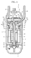
- FIG. 1 is a longitudinal sectional view of an enclosed compressor (fluid machine) according to the invention.
- An enclosed compressor (hereinafter, referred to as compressor) 1 is a vertical scroll compressor that is interposed in a refrigeration circuit, such as a refrigeration air conditioning unit and a heat pump water heater.
- the circuit includes a path through which a carbon dioxide refrigerant (hereinafter, referred to as a refrigerant) that is one of working fluids circulates.
- the compressor 1 sucks the refrigerant from the path, and compresses and discharges the refrigerant toward the path.
- the compressor 1 has a housing (container) 2.
- the housing 2 has a body 4, upper and lower sides of which are airtightly interfitted with an upper cover 6 and a lower cover 8, respectively.
- the body 4 is thus made airtight, so that high discharge pressure works within the body 4.
- the body 4 is connected with a suction pipe 10 for sucking the refrigerant retrieved from the circuit.
- a discharge pipe 12 for sending the compressed refrigerant in the housing 2 to the circuit is connected to a proper position of the upper cover 6.
- An electric motor 14 is accommodated in the body 4.
- a rotary shaft 16 is disposed in the motor 14 and driven when the power of the motor 14 is turned on.
- the rotary shaft 16 is rotatably supported by a spindle frame 18 at an upper end thereof through a bearing 17.
- the rotary shaft 16 is also rotatably supported by a countershaft frame 22 at a lower end thereof through a bearing 20.
- An oil pump 24 is mounted on the lower end of the rotary shaft 16.
- the pump 24 sucks lubrication oil L stored in an oil storage chamber 26 formed in the inside of the lower cover 8, that is, in a bottom of the housing 2.
- the lubrication oil L serves to lubricate sliding portions, bearings and the like, and functions as seal of sliding faces, passing through an oil supply path (oil path) 28 that is axially formed through the rotary shaft 16.
- Discharge pressure of the refrigerant acts on an oil level of the lubrication oil L contained in the oil storage chamber 26.
- the discharge pressure acting on the oil level of the lubrication oil L promotes the upward movement of the lubrication oil L through the oil supply path 28. This creates a high-pressure environment having a pressure that is substantially equal to the discharge pressure of the refrigerant at an outlet of the oil supply path 28.
- An inlet 32 for the lubrication oil L is formed in a proper position of the countershaft frame 22.
- the lubrication oil L supplied to the sliding portions of the compressor 1 is stored in the oil storage chamber 26 through the inlet 32.
- the refrigerant is sucked from the suction chamber 37 through the suction pipe 10 into the compression chamber.
- the compression chamber is reduced in capacity as it moves toward the center of the spiral wraps 34a and 36a. In this manner, the compression of the refrigerant is conducted.
- the movable scroll 34 is prevented from rotating on its axis by a rotation-blocking pin (pin) 62.
- the pin 62 is formed to project from the back face 34b of the movable scroll 34.
- the pin 62 is interfitted in a blind hole (cylindrical hole) 64 with allowance, which is formed in the spindle frame 18.
- a so-called pin hole-type rotation-blocking mechanism 60 is formed in a gap 45 between the back face 34b of the movable scroll 34 and the spindle frame 18.
- the rotation-blocking mechanism 60 is constructed to include, for example, four sets of pins 62 and holes 64.
- the fixed scroll 36 is fixed to the spindle frame 18 and separates a discharge chamber 54 side, which is formed under the upper cover 6, and the compression chamber from each other.
- the spindle frame 18 has a cylindrical outer circumferential wall 19 extending toward the fixed scroll 36 concentrically with the rotary shaft 16.
- the fixed scroll 36 is joined to an upper edge of the outer circumferential wall 19.
- the movable scroll 34 Since the fixed scroll 36 is joined to the upper edge of the outer circumferential wall 19, the movable scroll 34 is surrounded by the outer circumferential wall 19, and there is formed an orbit slide area, in which the movable scroll 34 makes sliding movement, in between the fixed scroll 36 and the spindle frame 18.
- a gap 46 In the orbit slide area, a gap 46 is so formed as to be surrounded by an upper face of the spindle frame 18, the end plate face of the fixed scroll 36, the movable scroll 34, and the outer circumferential wall 19.
- the gap 46 communicates with the suction chamber 37 and the gap 45.
- the gap 45 leads to the outlet of the oil supply path 28 and also with the suction chamber 37 through the gap 46.
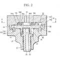
- the high-pressure lubrication oil L is supplied to the low-pressure suction chamber 37 through the gaps 45 and 46 (shown by arrows in FIG. 2 ). Consequently, the lubrication oil L seals a minute gap between the lateral faces of the spiral wraps 34a and 36a, which are the engaged surfaces, that between the top face 34c of the spiral wrap 34a and the end plate face 36d of the fixed scroll 36, and that between the top face 36c of the spiral wrap 36a and the end plate face 34d of the movable scroll 34.
- the grooves 35 are alternately formed in inner and outer circumferential surfaces of the spiral wrap 34a to obliquely extend from the middle of the top face 34c to the middle of the lateral face of the top face 34c, perpendicular to the inner and outer circumferential surfaces at given intervals in the direction of formation of the spiral wrap 34a.
- a groove width is set at a very small dimension (several ⁇ m, for example).
- each of the grooves 35 is set at a given dimension d1 that is shorter than a top-face width D in the top face 34c of the spiral wrap 34a.
- the given dimension d1 may be properly set in view of the strength of the spiral wrap 34a and the like (for example, d1/D ⁇ 1/2).
- a discharge hole 56 leading to the compression chamber side is formed through the fixed scroll 36 in a proper position of a central section thereof.
- the discharge hole 56 is opened and closed by a discharge valve 58 that is placed on the back face 36c side of the fixed scroll 36.
- the discharge valve 58 is covered with a discharge head 50, which reduces noises produced when the discharge valve 58 is opened.
- the high-pressure lubrication oil L discharged from the oil supply path 28 is supplied through the gaps 45 and 46 into the low-pressure suction chamber 37. Therefore, the minute gap between the spiral wraps 34a and 36a, that between the top face 34c and the end plate face 36d, and that between the top face 36c and the end plate face 34d are sealed with the lubrication oil L. Since the spiral wrap 34a is provided with the grooves 35 in the enclosed compressor according to the invention, the lubrication oil L is stored in the grooves 35 as shown by an arrow in FIG. 5 .
- the spiral wrap 34a repeatedly moves close to and away from the spiral wrap 36a so as to slide in a direction perpendicular to the lateral face of the spiral wrap 34a, that is, in a direction along the grooves 35. Therefore, the lubrication oil L stored in the grooves 35 is drawn out little by little to be supplied to between the top face 34c of the spiral wrap 34a and the end plate face 36d of the fixed scroll 36.
- the lubrication oil L is well supplied to the minute gap between the top face 36c of the spiral wrap 36a and the end plate face 34d of the movable scroll 34 as the gap is located below as viewed in a direction of gravitational force. Again, the minute gap between the top face 36c and the end plate face 34d is well sealed with the lubrication oil L.
- FIG. 6 is an enlarged perspective view of the spiral wrap 34a according to a second embodiment.
- FIG. 7 is a longitudinal sectional view, taken along line B'--B' of FIG. 6 .
- the second embodiment will be described below.
- each of the grooves 35' has a length (depth) that is set at a given dimension d2 shorter than the top-face width D.
- the given dimension d2 may be properly set in view of the strength of the spiral wrap 34a and the like (for example, d2/D ⁇ 1/2).
- the grooves 35' are arranged in this fashion, it is possible to successfully seal the minute gap between the top face 34c of the spiral wrap 34a and the end plate face 36d of the fixed scroll 36 while sufficiently storing the lubrication oil L in the grooves 35' by sucking up the lubrication oil L from the vicinity of the end plate face 34d in which a large amount of the lubrication oil L is relatively likely to exist as shown by the arrow in FIG. 7 .
- the grooves 35 and 35' are formed only in the spiral wrap 34a.
- the grooves are also provided to the spiral wrap 36a as well, the minute gap between the top face 36c of the spiral wrap 36a and the end plate face 34d of the movable scroll 34 can be still better sealed.
- the grooves 35 and 35' are formed in the inner and outer circumferential surfaces of the spiral wrap 34a, the grooves may be provided to either the inner or outer circumferential surface of the spiral wrap 34a. This makes it possible to ensure the strength of the spiral wrap 34a and to successfully seal the minute gap between the top face 34c of the spiral wrap 34a and the end plate face 36d of the fixed scroll 36.
Landscapes
- Engineering & Computer Science (AREA)
- Mechanical Engineering (AREA)
- General Engineering & Computer Science (AREA)
- Rotary Pumps (AREA)
- Applications Or Details Of Rotary Compressors (AREA)
Abstract
In a spiral wrap (34a) of at least a movable scroll, grooves (35) are formed at given intervals to extend from a halfway point of a top face (34c) of the spiral wrap through the lateral face of the spiral wrap, substantially perpendicular to the lateral face in a direction of formation of the spiral wrap.
Description
- The present invention relates to a fluid machine, and more specifically, to a fluid machine suitable for a refrigeration air conditioning unit and a heat pump water heater.
- A fluid machine of this type, for example, a scroll compressor, has a container accommodating a scroll unit that carries out a sequence of processes including the suction, compression and discharge of a refrigerant. More concretely, the scroll unit includes fixed and movable scrolls that engage with each other. A boss is formed in the back face of the movable scroll. This boss is coupled with a crank pin that is formed integrally with a rotary shaft. When driven by the rotary shaft through the boss, the movable scroll orbits around the axis of the fixed scroll without rotating on its axis while being supported by a spindle frame. This reduces the capacity of a gap formed between the spiral wraps of the scrolls. The sequence of the processes is then conducted.
- It is important for the fluid machine to prevent a refrigerant from leaking out by surely engaging the spiral wraps of the scrolls with each other to seal the gap formed between the spiral wraps. On the other hand, if the gap formed between the spiral wraps is sealed in this manner, friction that is caused in the engaged portions of the movable and fixed scrolls is increased. This could incur seizing or the like, and is therefore unfavorable.
- Given this factor, lubrication oil is usually supplied to the engaged portions of the movable and fixed scrolls so that a sealed condition may be retained by the sealing performance of the lubrication oil, and that seizing or the like may be prevented at the same time.
- As the lubrication oil supply easily breaks off especially between the upper surface of the spiral wrap of the movable scroll and the fixed scroll, various technologies have been suggested, which improve the lubrication oil supply to this particular portion. For example, in a well known configuration, a sloping face or the like is formed in the upper surface of a spiral wrap of a movable scroll to expand in an extending direction of the spiral wrap, and lubrication oil is directed to the upper surface of the spiral warp by using a wedge effect (see Unexamined Japanese Patent Publication No.
2005-171952 - The technology disclosed in the above publication, however, has the problem that, since the sloping face or the like is formed to expand in the direction of formation of the spiral wrap, the pressure in the compression chamber located in between spiral wraps is prone to decrease as it escapes along the sloping face to low-pressure portions other than the compression chamber due to the configuration of the scroll compressor.
- The decrease of the pressure in the compression chamber is not desirable because it leads to a reduction in sealing performance using lubrication oil, and then the compressor cannot provide sufficient compression efficiency.
- The present invention has been made in light of the above-described problems. It is an object of the invention to provide a fluid machine that is capable of surely supplying lubrication oil to engaged surfaces of movable and fixed scrolls, and constantly and successfully maintaining a compression chamber, which is formed between spiral wraps, in a liquid-tight state.
- In order to achieve the object, the fluid machine of the invention has a rotary shaft that extends within a container and is rotatably supported by the container; a crank pin that is formed integrally with the rotary shaft so as to be eccentrically located in an upper end of the rotary shaft; and a scroll unit that is installed in the container, has a fixed scroll formed integrally with the container and a movable scroll that orbits around an axis of the fixed scroll when coupled with the crank pin and driven by the rotary shaft, engages a lateral face of a spiral wrap formed upright in an end plate face of the movable scroll with a lateral face of a spiral wrap formed upright in an end plate face of the fixed scroll by using the orbiting motion of the movable scroll, engages a top face of the spiral wrap of the movable scroll with the end plate face of the fixed scroll, engages a top face of the spiral wrap of the fixed scroll with the end plate face of the movable scroll, and carries out a sequence of processes of compression and expansion of working fluid by increasing and decreasing the capacity of gaps formed between the spiral wraps. Lubrication oil is supplied to between the movable scroll and the fixed scroll. In the spiral wrap of at least the movable scroll, if not both the movable and fixed scrolls, grooves are formed at given intervals to extend from a halfway point of the top face of the spiral wrap through the lateral face of the spiral wrap, substantially perpendicular to the lateral face in a direction of formation of the spiral wrap.
- Consequently, working oil is stored in the grooves, and the stored lubrication oil is drawn out due to sliding movement of the top face of the spiral wrap and the end plate face and then supplied to between the top face of the spiral wrap and the end plate face. As a result, a minute gap between the top face of the spiral wrap and the end plate face is well sealed with the lubrication oil.
- Accordingly, all the minute gaps between the movable scroll and the fixed scroll, which are the engaged surfaces, can be well sealed with the lubrication oil. This makes it possible to successfully maintain the compression chamber, which is formed between the spiral wraps, in a liquid-tight state all the time.
- Preferably, each of the grooves is formed in the spiral wrap to extend halfway across the lateral face of the spiral wrap.
- Consequently, the minute gap between the top face of the spiral wrap and the end plate face can be well sealed by simple machining.
- Preferably, each of the grooves is formed to extend to the end plate face.
- It is then possible to successfully seal the minute gap between the top face of the spiral wrap and the end plate face of the fixed scroll while sufficiently storing the lubrication oil in the grooves by sucking up the lubrication oil from the vicinity of the end plate face in which a large amount of the lubrication oil is relatively likely to exist.
- Further preferably, the grooves are formed in at least either one of an inner circumferential surface and an outer circumferential surface of the spiral wrap.
- If the grooves are formed both in the inner and outer circumferential surfaces of the spiral wrap, the minute gap between the top face of the spiral wrap and the end plate face can be sufficiently well sealed. If the grooves are formed both in the inner and outer circumferential surfaces of the spiral wrap, the minute gap between the top face of the spiral wrap and the end plate face can be fully sealed.
-
-
FIG. 1 is a longitudinal sectional view of an enclosed compressor according to the invention; -
FIG. 2 is a view showing a scroll unit section ofFIG. 1 in an enlarged scale; -
FIG. 3 is a cross sectional view, taken along line AA ofFIG. 2 ; -
FIG. 4 is an enlarged perspective view of a spiral wrap of a movable scroll; -
FIG. 5 is a longitudinal sectional view, taken along line B--B ofFIG. 4 ; -
FIG. 6 is an enlarged perspective view of a spiral wrap of a movable scroll according to a second embodiment; and -
FIG. 7 is a longitudinal sectional view, taken along line B'--B' ofFIG. 6 . - One embodiment of the invention will be described below with reference to the attached drawings.
-
FIG. 1 is a longitudinal sectional view of an enclosed compressor (fluid machine) according to the invention. An enclosed compressor (hereinafter, referred to as compressor) 1 is a vertical scroll compressor that is interposed in a refrigeration circuit, such as a refrigeration air conditioning unit and a heat pump water heater. The circuit includes a path through which a carbon dioxide refrigerant (hereinafter, referred to as a refrigerant) that is one of working fluids circulates. Thecompressor 1 sucks the refrigerant from the path, and compresses and discharges the refrigerant toward the path. - As illustrated in
FIG. 1 , thecompressor 1 has a housing (container) 2. Thehousing 2 has abody 4, upper and lower sides of which are airtightly interfitted with anupper cover 6 and alower cover 8, respectively. Thebody 4 is thus made airtight, so that high discharge pressure works within thebody 4. Thebody 4 is connected with asuction pipe 10 for sucking the refrigerant retrieved from the circuit. Adischarge pipe 12 for sending the compressed refrigerant in thehousing 2 to the circuit is connected to a proper position of theupper cover 6. - An
electric motor 14 is accommodated in thebody 4. Arotary shaft 16 is disposed in themotor 14 and driven when the power of themotor 14 is turned on. Therotary shaft 16 is rotatably supported by aspindle frame 18 at an upper end thereof through abearing 17. - The
rotary shaft 16 is also rotatably supported by acountershaft frame 22 at a lower end thereof through abearing 20. Anoil pump 24 is mounted on the lower end of therotary shaft 16. Thepump 24 sucks lubrication oil L stored in anoil storage chamber 26 formed in the inside of thelower cover 8, that is, in a bottom of thehousing 2. The lubrication oil L serves to lubricate sliding portions, bearings and the like, and functions as seal of sliding faces, passing through an oil supply path (oil path) 28 that is axially formed through therotary shaft 16. - Discharge pressure of the refrigerant acts on an oil level of the lubrication oil L contained in the
oil storage chamber 26. The discharge pressure acting on the oil level of the lubrication oil L promotes the upward movement of the lubrication oil L through theoil supply path 28. This creates a high-pressure environment having a pressure that is substantially equal to the discharge pressure of the refrigerant at an outlet of theoil supply path 28. - An inlet 32 for the lubrication oil L is formed in a proper position of the
countershaft frame 22. The lubrication oil L supplied to the sliding portions of thecompressor 1 is stored in theoil storage chamber 26 through the inlet 32. - A
scroll unit 30 is set above themotor 14 within thebody 4 and carries out a sequence of processes including the suction, compression and discharge of a refrigerant. - More concretely, as illustrated in
FIG. 2 in an enlarged scale, thescroll unit 30 is formed of amovable scroll 34 and a fixedscroll 36. Thescrolls movable scroll 34 orbits around the fixedscroll 36, the spiral wraps 34a and 36a are engaged with each other to create asuction chamber 37 on an outer circumferential side of themovable scroll 34 in consort with each other. The refrigerant is sucked from thesuction chamber 37 through thesuction pipe 10 into the compression chamber. The compression chamber is reduced in capacity as it moves toward the center of the spiral wraps 34a and 36a. In this manner, the compression of the refrigerant is conducted. - To be more specific, as a result of the orbiting motion of the
movable scroll 34, lateral faces of the spiral wraps 34a and 36a are engaged with each other with a minute gap therebetween. At the same time, atop face 34c of thespiral wrap 34a and atop face 36c of thespiral wrap 36a are engaged with anend plate face 36d of the fixedscroll 36 and anend plate face 34d of themovable scroll 34, respectively, with minute gaps therebetween. The compression chamber is then increased and decreased in capacity, and the sequence of the processes including the suction, compression and discharge of the refrigerant is carried out. - In order to allow the orbiting motion of the
movable scroll 34, aboss 38 is convexly formed in aback face 34b of themovable scroll 34. Theboss 38 is fitted to a crankpin 42 through abearing 44. Thecrank pin 42 is integrally formed on the upper end side of therotary shaft 16 and causes themovable scroll 34 to orbit above thespindle frame 18 along with the rotation of therotary shaft 16. - The
movable scroll 34 is prevented from rotating on its axis by a rotation-blocking pin (pin) 62. Thepin 62 is formed to project from theback face 34b of themovable scroll 34. Thepin 62 is interfitted in a blind hole (cylindrical hole) 64 with allowance, which is formed in thespindle frame 18. In other words, a so-called pin hole-type rotation-blocking mechanism 60 is formed in agap 45 between theback face 34b of themovable scroll 34 and thespindle frame 18. The rotation-blocking mechanism 60 is constructed to include, for example, four sets ofpins 62 and holes 64. - The fixed
scroll 36 is fixed to thespindle frame 18 and separates adischarge chamber 54 side, which is formed under theupper cover 6, and the compression chamber from each other. Thespindle frame 18 has a cylindrical outercircumferential wall 19 extending toward the fixedscroll 36 concentrically with therotary shaft 16. The fixedscroll 36 is joined to an upper edge of the outercircumferential wall 19. - Since the fixed
scroll 36 is joined to the upper edge of the outercircumferential wall 19, themovable scroll 34 is surrounded by the outercircumferential wall 19, and there is formed an orbit slide area, in which themovable scroll 34 makes sliding movement, in between the fixedscroll 36 and thespindle frame 18. In the orbit slide area, agap 46 is so formed as to be surrounded by an upper face of thespindle frame 18, the end plate face of the fixedscroll 36, themovable scroll 34, and the outercircumferential wall 19. Thegap 46 communicates with thesuction chamber 37 and thegap 45. When themovable scroll 34 orbits in a direction of an arrow as illustrated inFIG. 3 , thegap 46 moves along with the orbiting motion. - As illustrated in
FIGS. 1 and2 , thegap 45 leads to the outlet of theoil supply path 28 and also with thesuction chamber 37 through thegap 46. The high-pressure lubrication oil L is supplied to the low-pressure suction chamber 37 through thegaps 45 and 46 (shown by arrows inFIG. 2 ). Consequently, the lubrication oil L seals a minute gap between the lateral faces of the spiral wraps 34a and 36a, which are the engaged surfaces, that between thetop face 34c of thespiral wrap 34a and theend plate face 36d of the fixedscroll 36, and that between thetop face 36c of thespiral wrap 36a and theend plate face 34d of themovable scroll 34. - As illustrated in
FIG. 3 showing a cross sectional view, taken along line A--A ofFIG. 2 , a plurality ofgrooves 35 are formed in all over the spiral wrap 34a of themovable scroll 34 over the length of thespiral wrap 34a in the direction of formation of thespiral wrap 34a. - As illustrated in
FIG. 4 showing an enlarged perspective view of thespiral wrap 34a, thegrooves 35 are alternately formed in inner and outer circumferential surfaces of the spiral wrap 34a to obliquely extend from the middle of thetop face 34c to the middle of the lateral face of thetop face 34c, perpendicular to the inner and outer circumferential surfaces at given intervals in the direction of formation of thespiral wrap 34a. A groove width is set at a very small dimension (several µm, for example). - As illustrated in
FIG. 5 showing a longitudinal sectional view, taken along line B--B ofFIG. 4 , the length of each of thegrooves 35 is set at a given dimension d1 that is shorter than a top-face width D in thetop face 34c of thespiral wrap 34a. The given dimension d1 may be properly set in view of the strength of thespiral wrap 34a and the like (for example, d1/D≤1/2). - A
discharge hole 56 leading to the compression chamber side is formed through the fixedscroll 36 in a proper position of a central section thereof. Thedischarge hole 56 is opened and closed by adischarge valve 58 that is placed on theback face 36c side of the fixedscroll 36. Thedischarge valve 58 is covered with adischarge head 50, which reduces noises produced when thedischarge valve 58 is opened. - Operation of the enclosed compressor (fluid machine) according to the invention thus constructed will be described below.
- According to the
compressor 1, when therotary shaft 16 is rotated by theelectric motor 14, themovable scroll 34 starts orbiting. The orbiting motion of themovable scroll 34 sucks the refrigerant from thesuction pipe 10 into thescroll unit 30 and compresses the refrigerant while reducing the capacity of the compression chamber. The high-pressure refrigerant thus compressed circulates through thehousing 2, and is discharged from thedischarge chamber 54 through thedischarge pipe 12 to the outside of the compressor. - If the
movable scroll 34 starts orbiting, the high-pressure lubrication oil L discharged from theoil supply path 28 is supplied through thegaps pressure suction chamber 37. Therefore, the minute gap between the spiral wraps 34a and 36a, that between thetop face 34c and theend plate face 36d, and that between thetop face 36c and theend plate face 34d are sealed with the lubrication oil L. Since thespiral wrap 34a is provided with thegrooves 35 in the enclosed compressor according to the invention, the lubrication oil L is stored in thegrooves 35 as shown by an arrow inFIG. 5 . - If the lubrication oil L is stored in the
grooves 35, and themovable scroll 34 makes orbiting motion, the spiral wrap 34a repeatedly moves close to and away from the spiral wrap 36a so as to slide in a direction perpendicular to the lateral face of thespiral wrap 34a, that is, in a direction along thegrooves 35. Therefore, the lubrication oil L stored in thegrooves 35 is drawn out little by little to be supplied to between thetop face 34c of thespiral wrap 34a and theend plate face 36d of the fixedscroll 36. Due to simple machining that forms thegrooves 35 obliquely from the halfway point of thetop face 34c to the halfway point of the lateral face, the minute gap between thetop face 34c and theend plate face 36d is sufficiently well sealed with the lubrication oil L. - The lubrication oil L is well supplied to the minute gap between the
top face 36c of thespiral wrap 36a and theend plate face 34d of themovable scroll 34 as the gap is located below as viewed in a direction of gravitational force. Again, the minute gap between thetop face 36c and theend plate face 34d is well sealed with the lubrication oil L. - Accordingly, all the minute gaps between the
movable scroll 34 and the fixedscroll 36, which are the engaged surfaces, can be well sealed with the lubrication oil L. This makes it possible to successfully maintain the compression chamber, which is formed between the spiral wraps 34a and 36a, in a liquid-tight state all the time. Thecompressor 1 is then increased in compression efficiency, which improves the performance of thecompressor 1. -
FIG. 6 is an enlarged perspective view of thespiral wrap 34a according to a second embodiment.FIG. 7 is a longitudinal sectional view, taken along line B'--B' ofFIG. 6 . The second embodiment will be described below. - According to the second embodiment, grooves 35' are arranged to extend from the middle of the
top face 34c through the lateral face up to theend plate face 34d of themovable scroll 34. Similarly to thegrooves 35, the grooves 35' are alternately formed in inner and outer circumferential surfaces of thespiral wrap 34a, perpendicular to the inner and outer circumferential surfaces at given intervals in the direction of formation of thespiral wrap 34a. Each of the grooves 35' has a groove width that is set at a very small dimension (several µm, for example). - To be concrete, as illustrated in
FIG. 7 , each of the grooves 35' has a length (depth) that is set at a given dimension d2 shorter than the top-face width D. The given dimension d2 may be properly set in view of the strength of thespiral wrap 34a and the like (for example, d2/D≤1/2). - If the grooves 35' are arranged in this fashion, it is possible to successfully seal the minute gap between the
top face 34c of thespiral wrap 34a and theend plate face 36d of the fixedscroll 36 while sufficiently storing the lubrication oil L in the grooves 35' by sucking up the lubrication oil L from the vicinity of theend plate face 34d in which a large amount of the lubrication oil L is relatively likely to exist as shown by the arrow inFIG. 7 . - This is the end of the description about the one embodiment of the invention. The invention, however, is not limited to the foregoing embodiments, and may be modified in various ways without deviating from the gist of the invention.
- For example, according to the embodiments, the
grooves 35 and 35' are formed only in thespiral wrap 34a. However, if the grooves are also provided to the spiral wrap 36a as well, the minute gap between thetop face 36c of thespiral wrap 36a and theend plate face 34d of themovable scroll 34 can be still better sealed. - Although, in the embodiments, the
grooves 35 and 35' are formed in the inner and outer circumferential surfaces of thespiral wrap 34a, the grooves may be provided to either the inner or outer circumferential surface of thespiral wrap 34a. This makes it possible to ensure the strength of thespiral wrap 34a and to successfully seal the minute gap between thetop face 34c of thespiral wrap 34a and theend plate face 36d of the fixedscroll 36. - According to the embodiments, the
grooves 35 and 35' are formed in the inner and outer circumferential surfaces of the spiral wrap 34a alternately at the given intervals, the grooves may be provided to the inner and outer circumferential surfaces to be located in the same positions at given intervals as long as the strength of thespiral wrap 34a is ensured. - The embodiments have been described, referring to the case in which the enclosed compressor is applied as a fluid machine. However, the invention is not limited to this case, and can be suitably applied as well when the fluid machine is an expansion device or the like.
Claims (4)
- A fluid machine characterized by:a rotary shaft (16) that extends within a container and is rotatably supported by the container (2);a crank pin (42) that is formed integrally with the rotary shaft so as to be eccentrically located in an upper end of the rotary shaft; anda scroll unit (30) that is installed in the container, has a fixed scroll (36) formed integrally with the container and a movable scroll (34) that orbits around an axis of the fixed scroll when coupled with the crank pin and driven by the rotary shaft, engages a lateral face of a spiral wrap formed upright in an end plate face of the movable scroll with a lateral face of a spiral wrap formed upright in an end plate face of the fixed scroll by using the orbiting motion of the movable scroll, engages a top face of the spiral wrap of the movable scroll with the end plate face of the fixed scroll, engages a top face of the spiral wrap of the fixed scroll with the end plate face of the movable scroll, and carries out a sequence of processes of compression and expansion of working fluid by increasing and decreasing the capacity of gaps formed between the spiral wraps, characterized in that:lubrication oil is supplied to between the movable scroll and the fixed scroll; andin the spiral wrap (34a) of at least the movable scroll, if not both the movable and fixed scrolls, grooves (35) are formed at given intervals to extend from a halfway point of the top face (34c) of the spiral wrap through the lateral face of the spiral wrap, substantially perpendicular to the lateral face in a direction of formation of the spiral wrap.
- The fluid machine according to claim 1, characterized in that:each of the grooves (35) is formed in the spiral wrap to extend halfway across the lateral face of the spiral wrap.
- The fluid machine according to claim 1, characterized in that:each of the grooves (35) is formed to extend to the end plate face (34d, 36d).
- The fluid machine according to any one of claims 1 to 3, characterized in that:the grooves (35) are formed in at least either one of an inner circumferential surface and an outer circumferential surface of the spiral wrap.
Applications Claiming Priority (1)
| Application Number | Priority Date | Filing Date | Title |
|---|---|---|---|
| JP2007106950A JP2008267150A (en) | 2007-04-16 | 2007-04-16 | Fluid machine |
Publications (1)
| Publication Number | Publication Date |
|---|---|
| EP1983197A1 true EP1983197A1 (en) | 2008-10-22 |
Family
ID=39671401
Family Applications (1)
| Application Number | Title | Priority Date | Filing Date |
|---|---|---|---|
| EP08007227A Withdrawn EP1983197A1 (en) | 2007-04-16 | 2008-04-11 | Fluid machine |
Country Status (4)
| Country | Link |
|---|---|
| US (1) | US20080273998A1 (en) |
| EP (1) | EP1983197A1 (en) |
| JP (1) | JP2008267150A (en) |
| CN (1) | CN101290011A (en) |
Families Citing this family (4)
| Publication number | Priority date | Publication date | Assignee | Title |
|---|---|---|---|---|
| US7556482B2 (en) * | 2005-06-29 | 2009-07-07 | Trane International Inc. | Scroll compressor with enhanced lubrication |
| KR102243681B1 (en) * | 2014-08-13 | 2021-04-23 | 엘지전자 주식회사 | Scroll Compressor |
| JP6685649B2 (en) * | 2015-03-17 | 2020-04-22 | 三菱重工サーマルシステムズ株式会社 | Scroll compressor |
| WO2020179051A1 (en) * | 2019-03-07 | 2020-09-10 | 三菱電機株式会社 | Scroll compressor |
Citations (2)
| Publication number | Priority date | Publication date | Assignee | Title |
|---|---|---|---|---|
| US5873711A (en) * | 1996-10-30 | 1999-02-23 | Carrier Corporation | Scroll compressor with reduced separating force between fixed and orbiting scroll members |
| JP2005171952A (en) | 2003-12-15 | 2005-06-30 | Matsushita Electric Ind Co Ltd | Scroll compressor |
Family Cites Families (10)
| Publication number | Priority date | Publication date | Assignee | Title |
|---|---|---|---|---|
| JPS6085285A (en) * | 1983-10-18 | 1985-05-14 | Hitachi Ltd | Scroll fluid machine |
| KR910001552B1 (en) * | 1985-05-16 | 1991-03-15 | 미쓰비시전기 주식회사 | Scroll type fluid transfering machine |
| DE3801156C2 (en) * | 1987-01-24 | 1998-09-24 | Volkswagen Ag | Scroll compressor |
| US5242283A (en) * | 1991-03-15 | 1993-09-07 | Kabushiki Kaisha Toyoda Jidoshokki Seisakusho | Scroll type compressor with elongated discharge port |
| JPH051882U (en) * | 1991-06-27 | 1993-01-14 | 株式会社豊田自動織機製作所 | Scroll compressor |
| JP3105729B2 (en) * | 1994-02-04 | 2000-11-06 | 三菱重工業株式会社 | Scroll compressor |
| US5591022A (en) * | 1995-10-18 | 1997-01-07 | General Motors Corporation | Scroll compressor with integral anti rotation means |
| US5781549A (en) * | 1996-02-23 | 1998-07-14 | Allied Telesyn International Corp. | Method and apparatus for switching data packets in a data network |
| US6808373B2 (en) * | 2002-09-27 | 2004-10-26 | Tokico Ltd. | Scroll fluid machine having projections on a wrap peripheral surface |
| US20070036668A1 (en) * | 2005-08-09 | 2007-02-15 | Carrier Corporation | Scroll compressor discharge port improvements |
-
2007
- 2007-04-16 JP JP2007106950A patent/JP2008267150A/en active Pending
-
2008
- 2008-04-11 EP EP08007227A patent/EP1983197A1/en not_active Withdrawn
- 2008-04-15 CN CNA2008100927888A patent/CN101290011A/en active Pending
- 2008-04-16 US US12/148,296 patent/US20080273998A1/en not_active Abandoned
Patent Citations (2)
| Publication number | Priority date | Publication date | Assignee | Title |
|---|---|---|---|---|
| US5873711A (en) * | 1996-10-30 | 1999-02-23 | Carrier Corporation | Scroll compressor with reduced separating force between fixed and orbiting scroll members |
| JP2005171952A (en) | 2003-12-15 | 2005-06-30 | Matsushita Electric Ind Co Ltd | Scroll compressor |
Also Published As
| Publication number | Publication date |
|---|---|
| US20080273998A1 (en) | 2008-11-06 |
| JP2008267150A (en) | 2008-11-06 |
| CN101290011A (en) | 2008-10-22 |
Similar Documents
| Publication | Publication Date | Title |
|---|---|---|
| US7815423B2 (en) | Compressor with fluid injection system | |
| US6773242B1 (en) | Scroll compressor with vapor injection | |
| EP2689137B1 (en) | Scroll compressor | |
| CN1598319B (en) | Scroll compressor | |
| US9239052B2 (en) | Scroll compressor having out-of-phase back pressure chamber and compression chamber oil-feeding paths | |
| US20080273998A1 (en) | Fluid machine | |
| WO2002061285A1 (en) | Scroll compressor | |
| JP5291423B2 (en) | Fluid machinery | |
| KR20060051788A (en) | compressor | |
| JP5209279B2 (en) | Scroll compressor | |
| KR101099094B1 (en) | Scroll compressor | |
| JP4301122B2 (en) | Scroll compressor | |
| JP2005105990A (en) | Scroll compressor | |
| JP4848844B2 (en) | Electric compressor | |
| JP5071355B2 (en) | Scroll compressor | |
| JP4301120B2 (en) | Scroll compressor | |
| JP4961178B2 (en) | Hermetic scroll compressor | |
| JP5097369B2 (en) | Hermetic scroll compressor | |
| CN100396930C (en) | scroll compressor | |
| JPH0727061A (en) | Scroll compressor | |
| JP2008144669A (en) | Scroll compressor and refrigeration cycle equipped with the same | |
| JP2005076545A (en) | Scroll compressor | |
| KR100548449B1 (en) | Scroll compressor prevents leakage of compressed gas | |
| JP4663293B2 (en) | Compressor | |
| JP2006214335A (en) | Scroll compressor |
Legal Events
| Date | Code | Title | Description |
|---|---|---|---|
| PUAI | Public reference made under article 153(3) epc to a published international application that has entered the european phase |
Free format text: ORIGINAL CODE: 0009012 |
|
| AK | Designated contracting states |
Kind code of ref document: A1 Designated state(s): AT BE BG CH CY CZ DE DK EE ES FI FR GB GR HR HU IE IS IT LI LT LU LV MC MT NL NO PL PT RO SE SI SK TR |
|
| AX | Request for extension of the european patent |
Extension state: AL BA MK RS |
|
| AKX | Designation fees paid | ||
| STAA | Information on the status of an ep patent application or granted ep patent |
Free format text: STATUS: THE APPLICATION IS DEEMED TO BE WITHDRAWN |
|
| 18D | Application deemed to be withdrawn |
Effective date: 20090423 |
|
| REG | Reference to a national code |
Ref country code: DE Ref legal event code: 8566 |