KR910001552B1 - Scroll type fluid transfering machine - Google Patents
Scroll type fluid transfering machine Download PDFInfo
- Publication number
- KR910001552B1 KR910001552B1 KR1019850008593A KR850008593A KR910001552B1 KR 910001552 B1 KR910001552 B1 KR 910001552B1 KR 1019850008593 A KR1019850008593 A KR 1019850008593A KR 850008593 A KR850008593 A KR 850008593A KR 910001552 B1 KR910001552 B1 KR 910001552B1
- Authority
- KR
- South Korea
- Prior art keywords
- scroll
- vortex
- spiral
- fine adjustment
- winding
- Prior art date
- Legal status (The legal status is an assumption and is not a legal conclusion. Google has not performed a legal analysis and makes no representation as to the accuracy of the status listed.)
- Expired
Links
- 239000012530 fluid Substances 0.000 title claims description 34
- 238000004804 winding Methods 0.000 claims description 96
- 239000000463 material Substances 0.000 claims description 11
- 230000007246 mechanism Effects 0.000 claims description 10
- 239000004033 plastic Substances 0.000 claims description 10
- 229910000679 solder Inorganic materials 0.000 claims description 4
- 239000002195 soluble material Substances 0.000 claims 1
- 230000006835 compression Effects 0.000 description 29
- 238000007906 compression Methods 0.000 description 29
- 238000000034 method Methods 0.000 description 19
- 238000007789 sealing Methods 0.000 description 16
- 239000003921 oil Substances 0.000 description 14
- 239000003507 refrigerant Substances 0.000 description 10
- 239000003566 sealing material Substances 0.000 description 9
- 238000010586 diagram Methods 0.000 description 8
- 230000002093 peripheral effect Effects 0.000 description 8
- 230000008878 coupling Effects 0.000 description 6
- 238000010168 coupling process Methods 0.000 description 6
- 238000005859 coupling reaction Methods 0.000 description 6
- 238000003825 pressing Methods 0.000 description 5
- 230000008859 change Effects 0.000 description 4
- 230000013011 mating Effects 0.000 description 4
- 238000005299 abrasion Methods 0.000 description 3
- 230000000694 effects Effects 0.000 description 3
- 239000007788 liquid Substances 0.000 description 3
- 239000010687 lubricating oil Substances 0.000 description 3
- 238000003466 welding Methods 0.000 description 3
- 229910000897 Babbitt (metal) Inorganic materials 0.000 description 2
- 230000000903 blocking effect Effects 0.000 description 2
- 238000007596 consolidation process Methods 0.000 description 2
- 230000006866 deterioration Effects 0.000 description 2
- 238000003780 insertion Methods 0.000 description 2
- 230000037431 insertion Effects 0.000 description 2
- 238000005461 lubrication Methods 0.000 description 2
- 230000010355 oscillation Effects 0.000 description 2
- 239000004810 polytetrafluoroethylene Substances 0.000 description 2
- 229920001343 polytetrafluoroethylene Polymers 0.000 description 2
- 230000002265 prevention Effects 0.000 description 2
- 239000007787 solid Substances 0.000 description 2
- 238000012546 transfer Methods 0.000 description 2
- 229910000838 Al alloy Inorganic materials 0.000 description 1
- 229910000906 Bronze Inorganic materials 0.000 description 1
- VGGSQFUCUMXWEO-UHFFFAOYSA-N Ethene Chemical compound C=C VGGSQFUCUMXWEO-UHFFFAOYSA-N 0.000 description 1
- 239000005977 Ethylene Substances 0.000 description 1
- KRHYYFGTRYWZRS-UHFFFAOYSA-M Fluoride anion Chemical compound [F-] KRHYYFGTRYWZRS-UHFFFAOYSA-M 0.000 description 1
- 240000002834 Paulownia tomentosa Species 0.000 description 1
- 230000002159 abnormal effect Effects 0.000 description 1
- 230000009471 action Effects 0.000 description 1
- 230000000712 assembly Effects 0.000 description 1
- 238000000429 assembly Methods 0.000 description 1
- 230000008901 benefit Effects 0.000 description 1
- 239000010974 bronze Substances 0.000 description 1
- 238000004891 communication Methods 0.000 description 1
- 230000008602 contraction Effects 0.000 description 1
- KUNSUQLRTQLHQQ-UHFFFAOYSA-N copper tin Chemical compound [Cu].[Sn] KUNSUQLRTQLHQQ-UHFFFAOYSA-N 0.000 description 1
- 238000002788 crimping Methods 0.000 description 1
- 230000003247 decreasing effect Effects 0.000 description 1
- 230000000593 degrading effect Effects 0.000 description 1
- PHAFDKCRJVKSSR-UHFFFAOYSA-N ethene hydrofluoride Chemical group F.C=C PHAFDKCRJVKSSR-UHFFFAOYSA-N 0.000 description 1
- 230000004927 fusion Effects 0.000 description 1
- 230000006872 improvement Effects 0.000 description 1
- 239000011133 lead Substances 0.000 description 1
- 210000004185 liver Anatomy 0.000 description 1
- 230000007774 longterm Effects 0.000 description 1
- 230000001050 lubricating effect Effects 0.000 description 1
- 210000002826 placenta Anatomy 0.000 description 1
- 230000009467 reduction Effects 0.000 description 1
- 239000011347 resin Substances 0.000 description 1
- 229920005989 resin Polymers 0.000 description 1
- 230000004044 response Effects 0.000 description 1
Images


Classifications
-
- F—MECHANICAL ENGINEERING; LIGHTING; HEATING; WEAPONS; BLASTING
- F04—POSITIVE - DISPLACEMENT MACHINES FOR LIQUIDS; PUMPS FOR LIQUIDS OR ELASTIC FLUIDS
- F04C—ROTARY-PISTON, OR OSCILLATING-PISTON, POSITIVE-DISPLACEMENT MACHINES FOR LIQUIDS; ROTARY-PISTON, OR OSCILLATING-PISTON, POSITIVE-DISPLACEMENT PUMPS
- F04C18/00—Rotary-piston pumps specially adapted for elastic fluids
- F04C18/02—Rotary-piston pumps specially adapted for elastic fluids of arcuate-engagement type, i.e. with circular translatory movement of co-operating members, each member having the same number of teeth or tooth-equivalents
- F04C18/063—Rotary-piston pumps specially adapted for elastic fluids of arcuate-engagement type, i.e. with circular translatory movement of co-operating members, each member having the same number of teeth or tooth-equivalents with coaxially-mounted members having continuously-changing circumferential spacing between them
-
- F—MECHANICAL ENGINEERING; LIGHTING; HEATING; WEAPONS; BLASTING
- F04—POSITIVE - DISPLACEMENT MACHINES FOR LIQUIDS; PUMPS FOR LIQUIDS OR ELASTIC FLUIDS
- F04C—ROTARY-PISTON, OR OSCILLATING-PISTON, POSITIVE-DISPLACEMENT MACHINES FOR LIQUIDS; ROTARY-PISTON, OR OSCILLATING-PISTON, POSITIVE-DISPLACEMENT PUMPS
- F04C27/00—Sealing arrangements in rotary-piston pumps specially adapted for elastic fluids
- F04C27/005—Axial sealings for working fluid
Landscapes
- Engineering & Computer Science (AREA)
- Mechanical Engineering (AREA)
- General Engineering & Computer Science (AREA)
- Rotary Pumps (AREA)
Abstract
내용 없음.No content.
Description
제1도는 이 발명의 제1의 실시예에 의한 시일(Seal), 미(微)조정기구를 구비한 스크롤 압축기의 단면도.1 is a cross-sectional view of a scroll compressor provided with a seal and a fine adjustment mechanism according to a first embodiment of the present invention.
제2도는 동 조립도.2 is an assembly diagram of the same.
제3도(a-c)∼제6도는 편심부쉬(Bush)의 구성간 작동을 설명하는 부분상세요도.Figs 3 (a-c) to 6 are parts for explaining the operation of the configuration of the eccentric bush.
제7도는 상기 제1실시예를 요동스크롤에 채용한 경우의 조립사시도.7 is an assembled perspective view of employing the first embodiment in the rocking scroll.
제8도∼제13도는 다른 조립방법을 설명하는 부분요도.8 to 13 are partial diagrams illustrating another assembling method.
제14도는 다른 실시예로 표시하는 부분단면도.14 is a partial cross-sectional view shown in another embodiment.
제15도는 다른 실시예의 조립상태를 표시하는 도면.15 is a view showing an assembled state of another embodiment.
제16도는 이 발명의 제2실시예 개선 전의 압련선도.16 is a consolidation diagram before improvement of the second embodiment of the present invention.
제17도는 제2실시예 개선 후의 요동스크롤 사시도.Fig. 17 is a perspective view of the rocking scroll after the second embodiment is improved.
제18도는 제2실시예 개선 후의 압련선도.18 is a consolidation diagram after the second embodiment is improved.
제19도-제22도는 제2실시예를 설명하는 부분요도.19-22 are partial diagrams illustrating a second embodiment.
제23도-제26도는 이 발명의 제3의 실시예를 설명하는 부분요도.23-26 are partial diagrams illustrating a third embodiment of this invention.
제27도는 이 발명의 제4의 실시예를 표시하는 부분단면도.Fig. 27 is a partial sectional view showing a fourth embodiment of this invention.
제28도는 제4의 실시예의 힘의 균형 설명도.28 is an explanatory diagram of the force balance of the fourth embodiment.
제29도는 스크롤 유체기계의 작동원리도.29 is a working principle of the scroll fluid machine.
제30도는 종래예의 국부단면도.30 is a local sectional view of a conventional example.
제31도-제34도는 다른 종래예의 국부단면도.31-34 are local cross-sectional views of another conventional example.
* 도면의 주요부분에 대한 설명* Description of the main parts of the drawings
1 : 고정스크롤 2 : 요동스크롤1: fixed scroll 2: rocking scroll
5 : 홈 6 : 미조정용엘레멘트5: groove 6: fine adjustment element
101, 102 : 와권측판 101α, 201α : 단면(斷面)101, 102: spiral winding side plate 101α, 201α: cross section
102, 202 : 받침판 51 : 융통공간102, 202: base 51: fusion space
510, 610 : 균압홈 611 : 간격510, 610: equalization groove 611: spacing
5b, 5c : 테이퍼측면5b, 5c: taper side
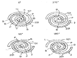
본 발명은 공기압축기 냉매압축기등의 압축기, 펌프, 펭창기등에 사용되는 스크롤유체기계의 간격미(微)미세한 간격의 조정기구에 관한 것이다. 스크롤 유체기계의 이름으로 알려진 유체기계의 원리는 옛부터 알려져 있으며 압축기, 펌프, 팽창기등 여러가지에 응용이 연구되오고 있다. 제29도는 스크롤 유체기계의 기본적인 구성요소를 표시하는 것이며 도면에서(1)은 고정스크롤, (2)는 요동스크롤, (1a)는 배출구, (P)는 압축실, (0)는 고정스크롤(1)상의 정점(定点), (0')는 요동스크롤(2)상의 정점이다. 고정스크롤(1) 및 요동스크롤(2)는 각각 후술하는 받침판상에 감은 방향이 반대이며 동일형상의 와권(渦卷)측판(101)(201)이 동일체로 형성되어 제29도와 같이 서로 짜맞추어져 있으며 B점 각부에서 와권측판(101)(201)은 서로 그의 축방향 측면을 접하고 있다. 이 와권측판(101)(201)의 형상은 종래부터 알려진대로 나선(Involute)곡선등으로 형성되어 있다. 다음에 본 스크롤유체기계가 압축기로서 작동하는 경우의 동작에 관하여 설명한다.BACKGROUND OF THE
제29도에 있어서 고정스크롤(1)은 공간에 대하여 정지하고 있으며 요동스크롤(2)는 고정스크롤(1)과 도면과 같이 짜맞추어져 그 자세를 공간에 제하며 변화시키지 않고 회전운동하며 제29도 0˚, 90˚, 180˚, 270˚와 같이 운동한다. 요동스크롤(2)의 운동에 수반하여 전기 각점 B는 중심을 향해 이동하며, 고정스크롤 와권측판(101) 및 요동스크롤 와권측판(201)의 사이에 형성된 초승달모양의 압축실(P)에 흡입된 기체는 압축되어서 배출구(la)에서 배출된다. 그동안에 제29도 0∼0"의 거리는 일정하게 유지되며 와권측판(101)(201)의 간격을 Z두께를 t로 하면![]()
![]()
이와 같은 작동원리로 작동하는 스크롤 유체기계의 구체적인 구성을 제30도에 의하여 설명한다. 제30도는 스크롤 유체기계를 압축기로서 응용한 경우의 한가지 종래예이다. 도면중(1)은 고정스크롤, (2)는 요동스크롤, (la)는 배출구, (P)는 압축실, (1b)는 흡입구, (3)은 주축, (4)는 프레임(Frame)이다. 또(101)(201)은 고정스크롤(1) 및 요동스크롤(2)의 각각 와권측판이며, (102)(202)는 고정스크롤(1) 및 요동스크롤(2)의 각각 받침판이다.30 illustrates a specific configuration of a scroll fluid machine that operates according to the operation principle. 30 shows one conventional example in which the scroll fluid machine is applied as a compressor. (1) is a fixed scroll, (2) is a rocking scroll, (la) is an outlet, (P) is a compression chamber, (1b) is an inlet, (3) is a main shaft, and (4) is a frame. . Further, 101 and 201 are vortex winding side plates of the
또 A는 와권측판(101)(201)의 단면(101a)(201a)와 이것에 각각 상접하는 상대측받침판(2O2)(102)의 밑면(202a)(102a)와의 사이의 축방향 간격이다.A is an axial gap between the
여기서 요동스크롤(2)는 받침판(202)의 와권측판(201)이 형성된면과 반대외면을 프레임(4)에 지지된 상태로 고정스크롤(1)과 제29도에 표시한 상태로 짜맞추며 고정스크롤(1)은 프레임(4)에 고정된다. 주축(3)이 화살표방향으로 회전하면 이것에 연결할 요동스크롤(2)이 운동을 시작한다.Here, the rocking scroll (2) is fixed and assembled in the state shown in the fixed scroll (1) and FIG. 29 with the outer surface opposite to the surface on which the vortex winding side plate (201) of the support plate (202) is formed on the frame (4). The
여기서 요동스크롤(2)은 도시아니한 자전방지장치에 의하여 자전하지 않는 공전운동을 한다. 그 결과 흡입구(1b)로 피압축유체가 흡인되어 제29도에 표시한 작동원리에 의하여 압축되고, 배출구(la)에서 배출된다.The rocking scroll (2) is an orbital movement that does not rotate by the rotation prevention device not shown. As a result, the compressed fluid is sucked into the
이와 같은 유체기계에 있어서 직경방향 시일 즉 간격(A)를 통하여 와권직경방향으로의 누출은 그 누출선의 길이가 와권의 긴쪽방향 길이에 상당하므로 그 유체 흡입용적에 비하여 상대적으로 크며 기계의 효율에 주는 영향은 크다. 이 직경방향을 시일하는 방법으로서는 간격(A)를 미소(微小)하게하며 예를 들면 일본국특개소 55-46081에 공지된 바와 같이 흡입구(1b)로 피압축유체와 함께 기름을 흡인시켜 미소간격(A)에 유막을 형성시켜서 피압축유체의 누출을 방지하는 수단을 생각할 수 있지만 이와 같은 미소간격을 균일하게 설치하기 위하여는 고정스크롤(1), 요동스크롤(2), 프레임(4)등 각부 칫수 높은 정밀도가 요구되어 경우에 따라서는 조립시에 각 부품의 선택맞춤을 하지않으면 않되는 등 공작 및 조립에 문제가 있었다.In such a fluid machine, the leakage in the vortex winding diameter direction through the radial seal, that is, the gap A, is relatively large compared to the fluid suction volume because the length of the leak line corresponds to the length of the vortex in the longitudinal direction. The impact is great. As a method of sealing the radial direction, the gap A is made small, and for example, as known in Japanese Patent Application Laid-Open No. 55-46081, the
또 운전시 배출구(1a)근방은 압축된 유체로 인하여 고온이되지만 그 결과 미소간격(A)이상으로 국부적인 열팽창이 있으면 빠져나가지 못하므로 타붙는 일이 생긴다. 따라서 열팽창량을 상정하여 미리 그분만큼(A)면 전체를 균일하게 그 간격을 크게 잡지않으면 않되지만 이와 같이하면 효과적인 유막을 형성하는데 필요한 최저간격이상이되어 결과로서 누출이 많으며 시일의 효과가 없어지는 경우가 많았다.In addition, during operation, the vicinity of the outlet 1a becomes high due to the compressed fluid, but as a result, if there is a local thermal expansion above the micro-interval (A), it does not escape, resulting in burning. Therefore, the amount of thermal expansion should be assumed in advance so that the entire surface of the (A) surface is not evenly spaced as much as it is. However, this results in more than the minimum gap needed to form an effective oil film, resulting in many leaks and the effect of sealing is lost. There were a lot.
한편 이러한 비접촉시일 이외에 와권측(101)(201)의 단면에 와권 긴쪽방향에 따라 홈을 형성하고 이 홈에 시일재를 집어넣어서 접촉시일에 의하여 유출을 방지하는 방법이 고려되고 있다.On the other hand, in addition to the non-contact seal, a method of forming a groove along the vortex winding longitudinal direction in the cross section of the
이와 같은 시일방법으로서는 멀리는 1905년의 미국특허제 801182호에 공시되고 있으며 또 최근의 것으로는 일본특개소 51-l17304호 등에 개시되어 있다. 일예로서 일본특개소 51-l17304호에 개시된 것을 제31도∼제33도에 의하여 설명한다.As such a sealing method, it is disclosed in U.S. Patent No. 801182 of 1905 as far away, and recently, it is disclosed in Japanese Patent Laid-Open No. 51-l17304. As an example, what is disclosed in Japanese Patent Laid-Open No. 51-l17304 will be described with reference to Figs.
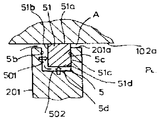
즉 제31도는 고정스크롤(1) 받침판 저면(102a)와 요동스크롤(2) 와권측면 단면(201a)과의 사이의 (A)부근방의 부분단면도이며 와권측판(201)의 단면(201a)의 와권긴쪽방향에 따라서 트인 단면구형 (袒免)의 홈(5)을 형성하고 이 홈(5)내에 홈(5)와 동형상의 시일재(51)을 집어넣고 있다.That is, FIG. 31 is a partial cross-sectional view of the vicinity of (A) between the fixed scroll (1) base plate bottom (102a), the swinging scroll (2), and the winding side
여기서 홈(5)측면(5b)와 시일재(51)측면(51b)과의 사이에는 와권긴쪽방향에 따라서 간격(502)가 설치되도록 홈(5) 및 시일재(51)의 칫수가 규정되어 그 결과 와권측판(201)의 단면(201a)와 받침판 저면(102a)의 사이에 간격(A)가 개재하여도 와권측판(201)에 의하여 칸막이된 고압측압축실(PH)와 저압측 압축실(PL)의 사이의 시일은 고압측 압축실(PH)로 부터 실선화살표로 표시한대로 간격(501)(502)에 가스가 유입하고 결과로서 화살표(F)같이 힘이 부하되기 때문에 시일재(51)은 받침판 저면(102a) 및 홈(5) 측면(5C)에 각각 시일재(51)의 상면(51a) 및 측면(51C)이 눌려 시일재(51)이 받침판 저면(102a) 홈측면(5C)에 밀착하여 가스유출은 방지된다.Here, the dimensions of the
이와 같은 시일방법에 있어서는 와권측판 단면과 받침판 저면간의 간격(A)를 통하여 와권직경방향으로의 유출에 대한 시일은 효과적으로 수행되나 와권측판(101)(201)동지에 의하여 점(B)에서 분할된 각 압축실(P)간에 있어서는 간격(501)(502)를 통하여 와권긴쪽방향으로 누출하기 쉬운 결점이있다.In such a seal method, the seal against the outflow in the vortex winding direction is effectively performed through the gap A between the end face of the vortex side plate and the bottom of the support plate, but is divided at the point B by the
즉 제32도는 와권측판(101)(201)의 접전(B)근방을 위에서 본 부분단면도, 제33도는 같은 부분단면 사시도 이지만 고압측압축실(PH)로부터 실선화살표로 표시한 바와 같이 가스가 간격(501)(502)를 통하여 하류측의 저압측압축실(PL) 누출하는 상태를 표시하고 있다.That is, FIG. 32 is a partial cross-sectional view of the vicinity of the contact (B) of the spiral winding
이와 같이 이 형식의 시일방법은 직결방향으로의 시일은 효과적이지만 그 수단으로서 홈(5)와 시일재(51)간의 간격(501)(502)을 설치하지 않으면 않되므로 그결과로서 와권긴쪽방향의 누출은 필연적으로 발생하며 압축 효율 즉 성능의 저하를 면할 수 없다.Thus, this type of sealing method is effective in sealing in the direct connection direction, but the
특히 공장 정밀도에 의한 간격(501)(502)의 칫수의 오차는 간격(501)(502)를 통과하는 누출의 증대나 시일재(51)의 추종성 자체의 저하에 의한 직경방향으로의 누출이 증대될 가능성이 있다. 또 시일재(51)의 상면(51a)는 가스에 의하여 받침판 저면(102a)로 눌려서 활동(活動)하기 때문에 이 부분의 활동손실이나 마모도 무시 못한다.In particular, the error in the dimensions of the
또 이와 같은 와권긴쪽방향으로의 누출을 방지하는 수단으로는 예를 들면 일본실개소 57-]80182에 있어서는 제34도에 표시한대로 시일재(51)의 폭칫수(D)와 홈(5)의 폭칫수(D')를 실질적으로 똑같이하고 시일재(51)의 두께칫수(H)를 홈(5)의 깊이칫수(H') 보다도 크게하므로서 해결하려하고 있다. 그러나 이 칫수에 있어서는 (H) 및 (H')의 칫수관리가 어렵고 만약 H-H'>A로 되면 축방향의 간격이 열리는 것이 되어 반경방향 누출이 생기는 것이되며 또 H-H'<A이면 시일재(51)이 고정스크롤(1)과 요동스크롤(2)에 끼워진형태로 되어 원활한 회전구동이 되지 않는다.As a means for preventing such leakage in the spirally wound direction, for example, in the Japanese room 57-] 80182, the width dimension D and the
이상과 같이 종래의 스크롤 유체기계에서는 비접촉시일방식에서 축방향 간격을 균일히 미소하게 하려면은 공작 정밀도등 정밀도 관리상의 문제가 있으며 더욱 간격을 좁히면은 와권의 치(齒)끝이 운전중의 열팽창등에 의하여 상접하여서 타붙는 등의 신뢰성에 문제가 있고 이것을 방지하기위하여 간격을 넓히면은 성능이 저하하는 상반된 문제점이 있었다.As mentioned above, in the conventional scroll fluid machine, in order to make the axial spacing uniformly small in the non-contact sealing method, there is a problem in the precision management such as the work accuracy, and when the spacing is narrowed further, the end of the spiral of the spiral wound is in thermal expansion during operation. There is a problem in reliability, such as sticking on and off, and widening the gap in order to prevent this has the opposite problem of degrading performance.
또 접촉시일 방식에 있어서는 시일재와 홈간에 간격을 설치하여 가스등에 의하여 추적밀봉시키는 경우 상기 간격으로부터의 누출에 의한 성능저하나 시일재의 마모가 문제된다. 또 시일재와 홈간의 간격을 설치하지 않고 시일재에 의하여 시일하는 경우 비접촉시일방식과 같이 엄밀한 정밀도 관리가 요구되는 등의 문제가 있었다.In addition, in the contact sealing method, when a gap is provided between the seal member and the groove and sealed by a gas or the like, there is a problem of deterioration due to leakage from the gap or wear of the seal member. In addition, when sealing with a sealing material without providing a gap between the sealing material and the groove, there is a problem such as a precise precision management required such as a non-contact sealing method.
본 발명은 그런한 문제점을 해결하기위한 것으로 구조가 간단하고 조립이 용이하며 그러면서도 공작 정밀도나 운전중의 열변형등도 허용할 수 있으면 운전중의 유출을 효과적으로 방지하여 효율좋고 신뢰성 높은 스크롤 유체기계의 조립 미조정기구를 제공함을 목적으로 하고 있다.The present invention is to solve such a problem, the structure is simple, easy to assemble, and can also allow the work precision and thermal deformation during operation, effectively prevents the leakage during operation of the efficient and reliable scroll fluid machine The purpose is to provide an assembly fine adjustment mechanism.
이 발명에 관한 스크롤 유체기계는 각각 나선형등의 와권측판을 받침판면에 돌출시켜서 형성된 고정스크롤 및 요동스크롤을 서로 짜맞추므로서 상기 각 와권측판 및 받침판에 의하여 복수의 실(室)을 형성하고 요동스크롤을 선회시켜서 상기실에 흡입된 유체를 이송, 압송 내지 팽창시키도록 구성한 스크롤 유체기계에 있어서 상기 양스크롤의 각 와권측판과 각각 동형상의 와권형상인 한쌍의 미조정용 엘레멘트와 이것을 와권축방향에 끼워 맞추는 같은 와권형상의 안내(Guide)홈을 상기 양스크롤의 와권측판 단면에 설치하여 상기 각미조정용 엘레멘트가 그것에 대응하는 상기 각 안내홈에 있어서 끼워맞출때 와권측방향으로 소성(塑性)변형하여 상기 각미조정용 엘레멘트를 통하여 상기 각와권측판단면과 이에 대응하는 받침판 저면간의 간격을 미조정할 수 있도록 한 것이며 또 상기 양스크롤의 각 와권측판과 각각 동형상의 와권형상인 한쌍의 미조정용 엘레멘트와 이것을 와권축방향에 압입(壓入)으로 끼워 맞추는 안내부를 상기 양스크롤의 와권측판의 단면에 설치하여 상기 각 미조정용 엘레멘트가 그것에 대응하는 상기 안내부에서 압입으로 끼워맞출때 와권축방향으로 이동하여서 상기 각 미조정용 엘레멘트를 통하여 상기 각와권측판단면과 이에 대응하는 받침판 저면간의 간격을 미조정할 수 있도록 상기 미조정용 엘레멘트와 안내부간에 축방향에 빈틈부가 있도록 하여서 빈틈부와 상기 실과를 상통시키도록 한 간격 미조정기구가 있는 것이다.The scroll fluid machine according to the present invention forms a plurality of seals by the vortex winding plates and the supporting plates, respectively, by fitting the fixed scroll and the swinging scroll formed by protruding a spiral winding plate such as a spiral onto the support plate surface, respectively, and oscillating scrolls. A scroll fluid machine configured to transfer, feed, or expand a fluid sucked into the chamber by turning a pair of fine adjustment elements each of which has a spiral shape and a spiral winding shape, each of which is wound in a spiral winding direction. A guide groove of the same vortex winding shape is provided on the vortex winding plate end surface of the both scrolls, and the plastic element is plastically deformed in the vortex winding direction when the fine adjustment element is fitted in each of the guide grooves corresponding thereto. The gap between the angle and the side plate end surface and the bottom surface of the supporting plate through the angle adjusting element And a pair of fine-tuning elements each having a spiral shape of the same shape as each spiral winding plate of both scrolls, and a guide portion that press-fits the spiral winding direction in the spiral winding direction. When the micro-adjustment element is fitted in the guide portion corresponding thereto by press-fitting, the micro-adjustment element moves in the and crimping direction so as to fine-adjust the gap between the angular and winding side plate cross-section and the corresponding base plate bottom surface through the micro-adjustment element. There is a gap fine adjustment mechanism so that the gap between the gap and the seal so that the gap between the fine adjustment element and the guide portion in the axial direction.
그리고 상기 양스크롤의 각 와권측판파 동형상의 와권형상인 미조정용 엘레멘트와 상기 양스크롤의 와권측판단면에 따라서 형성되고, 상기 미조정 엘레멘트가 압입된 안내홈과를 구비하고 상기 각 미조정용 엘레멘트의 상기 각 안내홈에 대한 압입깊이를 조정하므로서 상기 각 미조정용 엘레멘트 단면과 이에 대응하는 상기 각 받침판 저면간의 간격을 미조정 할 수 있도록 상기 안내홈의 축방향 단면형상을 저면홈폭에 비하여 트인부분의 홈폭을 넓게 형성하여 테이퍼형으로 한 것이다.And a guiding element having a vortex winding shape of each vortex winding plate wave shape of both scrolls and a vortex winding plate cross section of the both scrolls, and having a guide groove in which the fine adjustment element is press-fitted, The groove width of the open portion of the guide groove in the axial cross-sectional shape of the guide groove in relation to the bottom groove width so as to finely adjust the gap between the end surface of each of the fine adjustment elements and the corresponding bottom plate of the support plate by adjusting the press-in depth for each guide groove. To form a tapered shape.
상기와 같이 스크롤의 와권상의 측판단면에 설치한 안내홈에 축방향으로 소성변형시켜 균등하게 미조정용 엘레멘트를 끼워넣고 상기 미조정용 엘레멘트를 고정스크롤 및 요동스크롤의 각 와권측판단면과 받침판 저면간의 축방향간격의 미조정이 가능하며 고정스크롤, 요동스크롤 등의 공작정밀도의 오차를 배제하고 실질간격이 없는 혹은 필요한 최소한의 미소간격으로 조정할 수 있으며 또한 운전중 열적변형 등으로 엘레멘트가 받침판에 접속하여도 소성변형이 더욱 진행되거나 마모하여서 안전된 상태로 고정되며 누출이 적은 신뢰성 높은 간격 미조정기구를 제공할 수 있고 더구나 스크롤의 와권형상의 측판단면에 설치한 안내부에 균등하게 미조정용 엘레멘트를 압입하므로서 상기 미조정용 엘레멘트를 통하여 고정스크롤 및 요동스크롤의 각와권측판 단면과 받침판 단면간의 축방향 간격의 미조정이 가능하며 고정스크롤 요동스크롤 등의 공장정밀도의 오차를 배제하여 실질간격이 없는 혹은 필요한 최소한의 미소간격으로 조정할 수 있으며 또한 미조정용 엘레멘트와 안내부와의 사이에 축방향으로 빈틈부가 있도록하여 이 빈틈부와 상기 실을 상통시키도록 하였으므로 빈틈부와 실과의 사이는 대략 균압되므로 운전중 실의 압력변동에 의한 미조정용 엘레멘트의 축방향으로의 이동이 방지되며 따라서 미조정 엘레멘트에는 실질축 방향에는 힘이 발생아니하여 엘레멘트와 받침판간의 마찰저항이나 마모가 없으며 또 엘레멘트가 안내부안으로 함몰하는 일없이 안정된 상태로 고정되고, 누출이 적은 신뢰성 높은 간격 미조정 기구가 제공되며 또는 스크롤의 와권측판 단면에 설치한 안내홈에 균등하게 미조정용 엘레멘트를 압입하므로서 상기 미조정용 엘레멘트를 통하여 고정스크롤 및 요동스크롤의 각와권측판단면과 받침판 저면간의 축방향 간격의 미조정이 가능하며 고정스크롤, 요동스크롤등의 공작정밀도의 오차를 배제하여 실질 간격 없는 흑은 필요한 최소한의 미소간격으로 조정할 수 있으며 또한 안내홈이 역사다리꼴의 테이퍼형으로 되어있으므로 은전중 실내의 압력변동에 의한 미조정용 엘레멘트의 축방향으로의 이동이 방지되고 따라서 미조정용 엘레멘트가 안내홈안에 함몰하는 일없이 안정된 상태로 고정된다.Plastic deformation in the axial direction in the guide grooves provided on the side plate end surface of the vortex of the scroll as described above to equally insert the fine adjustment element and the shaft between the vortex side plate end surface of the fixed scroll and rocking scroll and the bottom of the support plate Fine adjustment of the direction gap is possible, and it can be adjusted to the smallest gap without the actual gap or necessary minimum by eliminating the error of work precision such as fixed scroll and rocking scroll, and even when the element is connected to the support plate due to thermal deformation during operation. The plastic deformation progresses or wears to secure a stable state and can provide a reliable gap-adjusting mechanism with low leakage. Moreover, by inserting the fine-adjusting element evenly into the guide part installed on the side plate section of the vortex of the scroll. Fixed scroll and rocking scroll angle through the fine adjustment element It is possible to fine-adjust the axial spacing between the section of the spiral winding side plate and the base of the support plate, and it can be adjusted to the smallest gap without the actual gap or the necessary minimum by excluding the factory precision error such as the fixed scroll rocking scroll. Since there is a gap in the axial direction between the gap and the seal so that the gap is in contact with the seal, the gap between the gap and the seal is approximately equalized, so that the movement of the unadjusted element in the axial direction due to the pressure variation of the seal during operation is prevented. Therefore, there is no force in the direction of the actual axis of the unadjusted element, so there is no frictional resistance or abrasion between the element and the support plate, and the element is fixed in a stable state without decaying into the guide part, and a reliable gap with little leakage Guide groove provided with mechanism or installed on the side of the spiral winding plate of the scroll Fine adjustment of the axial gap between the angle of the fixed scroll and rocking scroll and the side plate and the bottom of the backing plate is possible through the fine-tuning element evenly by injecting the fine adjustment element into the plate. Excluding the real gap, black can be adjusted to the smallest gap required, and because the guide groove is tapered with an inverted trapezoid, the movement of the unadjusted element in the axial direction is prevented due to the pressure fluctuations in the room during the transfer. The diaphragm element is fixed in a stable state without sinking in the guide groove.
이하 이 발명의 제1의 실시예를 제1도∼제15도에 의하여 설명한다.A first embodiment of the present invention will be described below with reference to FIGS.
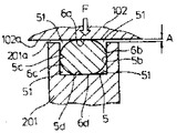
제1도는 스크롤 압축기를 전밀폐형 냉매압축기에 응용한 경우의 구체적인 1실시예이다. 도면중(1)은 고정스크롤, (2)는 요동스크롤, (1a)는 고정스크롤(1)의 중앙부에 설치된 배출구, (1b)는 고정스크롤(1)의 둘레벽부(103)에 형성된 흡입구, (P)는 압축실이다.FIG. 1 is a specific example of the case where the scroll compressor is applied to a hermetic refrigerant compressor. (1) is a fixed scroll, (2) is a rocking scroll, (1a) is a discharge port installed in the center of the fixed scroll (1), (1b) a suction port formed in the
또 고정스크롤(1)은 원판형의 받침판(102)와 이 받침판(102)에 동일체로 형성된 와권측판(101)로서 구성되고, 요동스크롤(2)도 똑같이 원판형와 받침판(202)에 동일체로 형성된 와권측판(201)로서 형성되며 양스크롤(1)(2)가 서로 물려서 받침판(102)(202)와 와권측판(101)(201)으로 포위된 압축실(P)가 형성되어있다.The fixed scroll (1) is composed of a disk-shaped support plate (102) and a spiral winding plate (101) formed in the same manner on the support plate (102), and the rocking scroll (2) is similarly formed on the disk and support plate (202). The compression chamber P formed as the spiral winding
이 압력실(P)는 복수개 형성되어 과중에서 가장압력이 높은 중앙부의 압력실이 배출구(la)에 상통하게끔 구성되어 있다.A plurality of pressure chambers P are formed, and the pressure chamber of the center part which has the highest pressure among the overloads is comprised so that the discharge port la may be made to communicate.
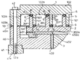
상기 와권측판(101)(201)의 각 단면(101a)(201a)에는 각각 와권긴쪽 방향에 따라 그르면서도 와권방향 내단부 및 외단부를 남겨놓고 안내부인 홈(5)가 각각 형성되며 이들 각 홈(5)에는 미조정용 엘레멘트(6)이 각각 끼워 맞추어져있다. 이 엘레멘트(6)은 홈(5)에 안내되어 홈(5)에 전기엘레멘트(6)의 양측면이 와권긴쪽방향에 완전히 밀착상태가 되도록 압입되어있다. 또 (3)은 주축, (301)은 와권측판(101)(201)이 마모되어도 이들 양측판(101)(201)의 측면이 항상 B부에서 접촉하도록 요동스크롤(2)에 압력을 주는 편심부쉬, (40)는 외주부면 형상이 고정스크롤(1)과 대략 같으며 그르면서도 최대외경이 고정스크롤(1)과 같은 상부프레임, (41)은 외주부면 형상이 교정스크롤(1)과 대략같으며 그르면서도 최대외경이 상부프레임(40)보다도 큰 하부프레임, (401)은 올담커플링, (402)는 압축실(P)의 압력 및 요동스크롤(2)의 자중을 받는 환상의 상부드러스트베어링, (411)은 주축(3)의 자중과 주축(3)에 걸리는 다른 드러스트하중을 받는 환상의 하부드러스트베어링, (403)은 주축(3)의 레이디얼 하중을 그의 상부로 받는 상부메인 베어링으로서 이 실시예에서는 베어링메탈을 사용하고 있다. (412)는 주축(3)의 레이디얼 하중을 그 중간부에서 받는 하부 메인베어링으로 이 실시예에서는 베어링 메탈을 사용하고 있다. 요동스크롤(2)의 받침판(202)의 배면(202b) 중심부에는 축심이 받침판(202)의 배면(202b)에 대하여 수직으로 주축(3)의 축심에 대하여 평행인축(203)이 한쌍으로 형성되어 있으며 또 주축(3)의 상단면에는 주축(3)의 축심(회전중심)에 평행인 축심이있는 편심공(3a)가 형성되어있어 이 편심공(3a)에 회전 자유롭게 편심부쉬(301)이 끼워져있다.In each
이 편심부쉬(301)은 그의 외주에 대하여 편심하고 축심이 주축(3)의 축심과 평행인 편심공(301a)가 있으며 이 편심공(301a)에는 상기 축(203)이 회전 자유롭게 끼워져 있다. 주축(3)은 상부프레임(40)에 설치된 상부메인베어링(403) 하부프레임(41)에 설치된 하부드러스트베어링(411) 및 하부메인베어링(412)에 의하여 지지되고 있으며 상부프레임(40) 하부프레임(41)은 상부메인베어링(403) 하부메인베어링(412)가 서로 동심이 되도록 끼워 맞추어져 있다.The
또 상부메인베어링(403)과 상부드러스트베어링(402)는 동심이며 상부메인베어링(403)축심과 상부드러스트베어링(402)의 베어링면(402a)가 수직이므로 수축(3)은 그 축심이 상부드러스트베어링(402)의 축심에 대하여 동심이 되며 또 상부드러스트베어링(402)의 베어링면(402a)에 대하여 수직으로 유지된다.In addition, since the upper
또 요동스크롤(2)는 그 받침판(202)의 배면(202b)에서 상기 상부드러스트베어링(402) 베어링(402) 베어링면(402a)에 의하여 지지되어 있으므로 요동스크롤(2)의 받침판(202)는 주축(3)에 대하여 수직인 자세로 유지된다. 을담 커플링(401)은 요동스크롤(2)의 자전을 방지하고 요동스크롤(2)가 주축(3)의 축심주위에 공전운동만을 하도록 하기 위한 커플링 수단이며 요동스크롤(2)의 받침판(202)는 상부프레임(40)과의 사이에 설치 되어있다. 상기 각부기구 부품이 상기와 같은 상대적인 관계로 조립된 후 고정스크롤(1) 및 요동스크롤(2)의 각 홈(5)에 각 미조정용 엘레멘트(6)이 각 홈(5)보다도 크게 돌출한 상태로 장치되어 상부프레임(40) 하부프레임(41) 고정스크롤(1)과는 고정스크롤(1)의 둘레벽부(103)과 상부프레임(40)과를 관통하고 선단의 나사부(42a)가 하부프레임(41)에만 나사 맞춤하는 복수개의 볼트(42)에 의하여 함께 조여진다. 이 상태를 제2도에 표시한다.The rocking
여기서 고정스크롤(1)은 둘레벽부(103)의 하면(103a)에서 상부프레임(40)의 외주부상면에 형성된 장치면(40a)에 고정되지만 상부프레임(40)의 장치면(40a)는 상부드러스트베어링(402)의 베어링면(402a)와 평행이며 요동스크롤(2)의 받침판(202)의 배면(202b)와 이와 반대면인 저면(202a) 및 와권측판(201)의 단면(201a)는 각각 평행이며 또한 고정스크롤(1)의 둘레벽부하면(103a)와 와권측판(101)의 단면(101a)는 동일면상에 있으며 상기 단면(101a)와 받침판(102)의 저면(102a)는 평행이므로, 고정스크롤(1)의 와권측판단면(101a)와 요동스크롤(2)의 받침판 저면(202a) 및 요동스크롤 (2)의 와권측판단면(201a)와 고정스크롤(1)의 받침판 저면(102a)간은 각각 평행으로 유지된다.The fixed scroll (1) is fixed to the device surface (40a) formed on the outer peripheral surface of the
그 때문에 전기 각 엘레멘트(6)은 각각 고정스크롤(1)의 받침판 저면(102a) 요동스크롤(2)의 받침판 저면(202a)에 의하여 눌려서 균일하게 전기홈(5)내로 압입된다. 그리고 상기 고정스크롤(1)이 상기 프레임(40)을 통하여 프레임(41)에 볼트(42)에 의하여 같이 조여진 상태에 있어서 상기 고정스크롤(1)의 와권측판 단면(101a)와 요동스크롤(2)의 반침판 저면(202a) 및 요동스크롤(2)의 와권측판 단면(201a)와 고정 스크롤(1)의 받침판 저면(102a)간에는 균일하게 미소간격 (A)가 형성되므로 이 미소간격(A)만큼 각 홈(5)보다도 균일히 돌출한 상태가 될 때까지 전기 각 엘레멘트(6)을 전기 각 홈(5)안으로 압입시킨 곳에서 정지 하게한다. 그 결과 와권측판 단면(101a)(201a)와 상대방의 각 받침판 저면(202a)(102a)간에는 상기 엘레멘트(6)을 두고 실제간격이 없어진다.Therefore, each
다음에 제1도에 있어서 주축(3)을 회전시키는 모터의 지지는 모터의 모터(70)이 주축(3)에 수축끼워맞춤등에 의하여 고정되고 상기 모터(70)와 적당한 빈틈(air gap)을 확보 조정하면서 모터의 고정자(71)이 하부프레임(41)에 볼트 등에 의하여 고착되어있다.Next, in FIG. 1, the support of the motor which rotates the
상기 각 기구부품을 상기와 같은 상대적 관계로 조립한 기구부품(8) 즉 고정스크롤(1), 요동스크롤(2), 상부프레임(40), 하부프레임(41), 주축(3), 모터(70), 고정자(71)등의 조립품은 밀폐용기인 셀(Cell)(9)에 수용되어 있다.The mechanical parts 8 in which the respective mechanical parts are assembled in the above relative relationship, that is, the fixed
여기서 셀(9)는 상부뚜껑(901) 중간원통부(902) 밑뚜껑(903)으로 3분할되고 기계부분(8)은 하부프레임(41) 외주부에 있어서 중간원통부(902)에 수축끼워맞춤 혹은 국부용접등에 의하여 고정되며 상부뚜껑(901) 밑뚜껑(903)은 전기중간 원통부(902) 양단면에 있어서 도면에서와 같이 중간원통부(902) 외주부를 덮는듯이 끼워맞추어서 이들 끼워맞춤부분을 용접밀봉하고 있다. (904)는 셀중간 원통부의 둘레벽의 용접등으로 접속되고 셀(9) 내부공간(9a)로 트인 흡입관, (905)는 셀 상부뚜껑(901)의 중앙부를 관통하여 이 중앙부로 기밀(氣密)하게 접속되어 또한 고정스크롤(1)의 배출구(1a)에 상통되도록 연장된 배출관, (906)을 셀 상부뚜껑(901)에 용접되어 도시아니한 리드(lead)선에 의하여 모터고정자(71)와 전기적으로 접속된 밀봉단자, (907)은 셀(9)의 저부에 괴인 윤활유이다. 여기서 주축(3)의 하단부는 윤활유(907)에 담겨져 있다. 또 전기배출관(905)와 배출구(1a)의 결합부는 0링 등에 의하여 밀봉되어있다. 주축(3)에는 주축(3)하단부에서 상단부로 형성된 편심공(3a)까지 관통한 편심급유공(3b)가 형성되고 베어링 각부로 급유되도록 되어있다.Here, the
이와 각이 구성된 스크롤 압축기의 동작을 아래에 설명한다.The operation of the scroll compressor configured with this angle will be described below.
밀봉단자(906)을 통하여 모터고정자(71)에 통전하면 모터로터(70)은 토오크를 발생하여 주축(3)과 함께 회전한다. 주축(3)이 회전하기 시작하면 주축(3)의 편심공(3a)에 끼워진 편심부쉬(301)을 통하여 요동스크롤(2)의 축(203)에 주축(3)의 회전력이 전달되어 요동스크롤(2)는 올담커블링(401)에 안내되어 자전하는 일없이 주축(3)의 축심을 중심으로 하는 공전운동을 하며 제29도에 표시한 상술과 같은 압축작용이 압축실(P)에서 수행된다.When the
이 경우 와권측판(101)(201)의 단면(101a)(201a)와 이들에 대면하는 받침판(202)(102)의 저면(202a)(102a)간의 미소간격(A)를 메우는듯이 홈(5)에 끼운 엘레멘트(6)이 받침판 저면(202a)(102a)의 방향에 실질간격이 없는 상태로 균일하게 상기 단면(101a)(201a)보다도 돌출되어 있으므로, 상기 미소간격(A)를 통하여 와권직경방향 즉 상대적인 고압의 압축실에서 저압의 압축실로의 압축냉매가스 유출의 발생을 방지한다. 또 와권측판(101)(201)의 측면동지는 요동스크롤(2)가 편심회전운동 함으로써 발생하는 원심력등을 이용하여 편심부쉬(301)을 요동스크롤(2)의 축(203)의 둘레에 요동시켜 주축(3)의 축심에 대한 요동시크롤(2)의 편심량을 가변으로 하는 것에 의하여 와권측판(101)(201)의 측면동지가 B부에서 상접되어서 상기 상대적인 고압의 압축실로부터 저압의 압축실로의 압축냉매의 누출이 와권측판(101)(201)의 측면간을 통하여 와권방향으로 발생하는 것이 방지된다.In this case, the
이와 같이 하여 압축시의 누출은 대부분 방지되어 압축효율이 높은 운전이 가능하다. 다음에 냉매가스의 흐름에 대하여 설명한다. 증발기(도시없음)로부터의 흡입냉매가스는 흡입관(904)에서 셀내공간(9a)로 유입하여 모터로터(70), 모터고정자(71)등을 냉각함과 동시에 도시 아니한 하부프레임(41) 외주부에 설치된 흡입통로를 통과하여 흡입구(1b)로 흡입되어 압축실(P)로 들어가 압축된 후 고압냉매가스로 되어 배출구(1a)를 경유하여 배출관(905)에서 셀(9) 밖으로 배출되어서 응축기(도시아니함)로 간다.In this way, most of the leakage during compression is prevented, so that the operation with high compression efficiency is possible. Next, the flow of the refrigerant gas will be described. The suction refrigerant gas from the evaporator (not shown) flows into the inner cell space 9a from the suction pipe 904 to cool the motor rotor 70, the
다음에 급유계에 관하여 설명한다. 셀(9)의 하부에 괴인 윤활유(907)은 주축(3)의 회전에 의하여 발생하는 원심펌프 작용에 의하여 편심 급유공(3b)를 경유하여 편심공(3a)에 길어올려져 편심부쉬 (301)에 급유된다. 주축(3) 편심부쉬(301)에 설치된 유공, 기름홈(도시아니함)등에서 상부드러스트베어링(402) 하부드러스트베어링(411), 상부메인베링(403), 하부메인베어링(412) 그 외에 올담커플링 (401)을 윤활시킨 후 일부는 압축실(P)로 흡입냉매가스와 더불어 흡입되어 압축의 시일 및 윤활에 사용되고 배출관(905)에서 배출되며, 응축기, 증발기(도시아니함)을 통과하여서 다시 흡입관(904)를 경유하여 셀(9)안으로 돌아오지만 태반은 상부프레임(40) 하부프레임(41)에 각각 설치된 환유공(40b) (41a)를 통하여 셀(9) 하부로 흘러내려 돌아오게 된다.Next, the oil supply system will be described. Lubricating
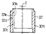
제3도는 주축(3)의 편심공(3a)에 삽입된 편심부쉬(301)의 구성을 상세하게 표시하는 도면으로(a)는 상면도, (b)는 측면단면도, (c)는 하면도이다. (301b)는 편심부쉬 외주면이며, OBO는 그 중심이다. (301a)는 편심부쉬 내주면이며, OBi는 그 중심이다. 중심 OBi는 OBO에 대하여 ε만큼 편심하고 있다. (301c)는 하단이 펀심부쉬 하단면으로 트여있고 상단부는 핀심부쉬 상단면으로 트이지 않도록 닫쳐진 상태로 형성된 종방향으로 뻗어있는 기름홈으로서 상기 내주면(301a)에 연결되고 있다. (301d)는 상기 기름홈(301c)와 외주면부(301b)와를 상통시키기위한 유공, (301c)는 상기 외주면부(301b)에 설치된 절개부로서 상기유공(301d)의 직경방향 외단이 이 절개부로 구멍이 트여있다. (301f)는 편심부쉬(301)의 두꺼운 부분에서 편심부쉬 하단면으로 뚫린 회전저지용 구멍이다. 또한 편심부쉬(301)은 알미늄합금, 연, 청동등의 베어링재로 제작된다.3 is a diagram showing in detail the configuration of the
제4도는 이와 같은 편심부쉬(301)을 주축(3)에 장치하는 경우의 조립순서를 설명하기 위한 사시도이다. 제4도에 있어서 먼저 주축(3)의 편심공(3a)저부의 핀공9(31)에 평면형상이 C형의 개략통(筒)형으로 된 스프링(32)를 끼워 맞춘 후, 이 스프링핀(32)에 편심부S1 (301)하부의 회전저지용 구멍(301f)가 맞도록 편심부쉬(301)를 편심공(3a)에 끼운다. 회전저지용 구멍 (301f)에 스프링핀(32)가 끼워져 편심부쉬(301)의 하단면이 편심공(3a)의 저면에 상접한 상태로 스냅링(33)을 편심공(3a)측면원주방향이 형성된 스냅링홈(34)에 끼운다. 스냅링(33)은 가는 피아노선등의 탄성선을 C형으로 형성한 것이다.4 is a perspective view for explaining the assembling procedure when the
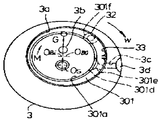
제 5도는 편심부쉬(301)을 주축(3)에 조립한상태를 표시하는 도면이며 이 제5도에 있어서(Os)는 주축(3)의 축심측 회전중심이며, 이 중심(Os)와 상기 편심부쉬 내주면(301a)의 중심(OBi)와를 잇는 직선과 상기중심(OBi)와 상기 편심부쉬 외주면(301b)의 중심과를 잇는 직선이 대략 직각으로 되는 위치에 상기 중심(OBO)이 위치하도록 스프링핀(32)의 위치가 결정되어 있다. 회전저지용 구멍(301f)의 직경은 스프링핀(32)의 직경보다 크게 잡으며 편심부쉬(301)의 둘레방향에 어느 정도 움직일 수 있도록 하고 있다.5 is a view showing a state in which the
또 편심부쉬(301)의 유공(301d)와 주축(3)의 최대 직경부 반경방향으로 설치된 유공(3C)가 편심부쉬(301)의 회전운동에 의하여도 항상 상통하도록 절개부(301e)는 둘레방향으로 소정의 거리만큼 형성되어 있다. 상기 유공(3C)는 또한 주축(3) 최대직경부 외주면 축방향에 설치된 기름홈(3d)에 상통하고 있다. 요동스크롤(2)의 요동축(203)은 편심부쉬(301)내에 요동축(203) 외주면이 내주면(301a)와 활동(活動) 가능하도록 끼워넣으므로서 상기 편심부쉬 내주면(301a)의 중심(OBi)는 요동중심 즉 요동스크롤(2)의 중심(重心)과 일치한다.In addition, the
따라서 화살로 W방향에 주축(3)이 회전하면 상기 주축(3)의 회전중심(Os)와 상기 편심부쉬내주면(301a)의 중심(OBi)와를 잇는 직선상에 화살표 G방향에 원심력이 발생하고 편심부쉬(301)은 상기 편심부쉬 외주면(301b)의 중심(OBO)를 중심으로 화살표 M방향으로 모멘트가 발생한다.Therefore, when the
따라서 만약 고정스크롤(1)과 요동스크롤(2)의 와권측판(101)(201)간에 간격이 있는 경우 이들 양측판(101)(201)이 서로 접할때까지 요동스크롤(2)가 이동하도록 편심부쉬(301)은 상기 편심부쉬 외주면(301b)의 중심을 중심으로 화살표 M방향으로 회전한다.Therefore, if there is a gap between the
제6도에 의하여 상기 중심위치의 변화를 설명한다. 즉 편심부쉬 외주면(301b)의 중심(OBO)를 중심으로하여 편심부쉬(301)은 화살표 M방향에 회전하고 편심부쉬 내주면(301a)의 중심(OBi)는 와권측판(101)(20l)이 서로 접하는 점(OBi)까지 이동한다. 즉 요동스크롤(2)의 공전반경은![]()
![]()
또 역으로 공작정밀도에 의하여 공전반경이 R보다 작은 겅우는 화살표 M와 반대방향으로 편심부쉬는 회전한다. 이것은 액백(液Back)이나 양와권측판(101)(201)사이로 이물(異物)이 끼는 경우도 발생한다.Conversely, due to the work precision, the eccentric bush rotates in the opposite direction to the arrow M, which has a smaller radius than R. This also occurs when a foreign material is caught between the liquid back and the right and left
이와 같이 편심부쉬(5)는 공작정밀도의 오차를 흡수하고 조립을 용이하게하며 그러면서도 압축시에 양와권측판(101)(201)간을 통하여 와권방향으로 압축냉매가스가 누출되는 것을 방지하여서 압축효율을 향상시키며 또 액백이나 이물이 끼는 것에 대하여도 내력(耐力)이 있으며 신뢰성의 향상에도 도움이 되는 것이다. 다음에 본 발명의 제 1의 실시예를 구체적으로 설명한다.In this way, the
제7도는 전기엘레멘트(6)을 요동스크롤(2)의 와권측판(201)의 단면(201a)로 홈이트이고 와권긴쪽방향에 따라서 형성된 홈(5)로 압입하는 상태를 표시하는 조립시의 사시도이다. 홈(5)는 와권측판(201)의 단면(201a)로 홈을 트고 그러면서 와권방향 내단부(201b) 및 외단부(201c)를 제외하고 와권긴쪽 방향에 따라 형성되어있으며 이 홈(5)를 메꾸는 듯이 줄모양의 엘레멘트(6)을 홈(5)의 트인 면에 수직으로 압입한다.7 is a perspective view at the time of assembly in which the
여기서는 요동스크롤(2)의 예를 표시하지만 고정스크롤(1)에 대하여도 똑같이 실시됨은 말할 것도 없다.Here, an example of the swinging
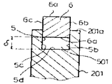
이하 요동스크롤(2)에 한하여 설명한다. 제8도는 이러한 상태에 있어서 국부단면도이며 상기 홈(5) 및 엘레멘트(6)은 여기서는 단면구형의 형성으로 되어 있다. 여기서 엘레멘트(6)의 폭칫수 D는 홈의 폭칫수D'와 실질동등 이상의 칫수이며 또 엘레멘트(6)의 두께칫수 H는 홈(5)의 깊이칫수 H'의 실질동등이든가 그것보다 작은 칫수로 되어 있다. D>D'인 경우는 엘레멘트(6)은 폭방향에 탄선변형 내지 소성변형하기 쉬운 재질이 아니면 않되고 따라서 엘레멘트(6)으로서는 그와 같은 성질이 있는 것이 사용된다. 어느 정도의 탄소성(彈塑性) 가요성(可撓性)이 있고 또한 자기윤활성이 있는 태트라 불화 에틸렌수지(PTFE)등은 최적이다. 또 연, 땜납같은 연질의 소성변형하기 쉬운 금속이나 고무같이 탄력이 큰 재질을 PTFE를 복합시킨 재료 등도 괜찮다.Hereinafter, only the rocking
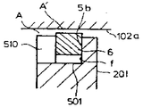
제9도는 이 같은 엘레멘트(6)을 홈(5)안에 삽입한 상태를 표시하는 국부단면도이며 엘레멘트(6)은 탄성변형(소성변형하여도 된다)하여 양측면(6b)(6c)가 홈(5)의 양측면(5b)(5c)와 밀착한 상태로 와권측판 단면(201a)에서 돌출된 상태 따라서 엘레멘트(6)의 하면(6d)와 홈(5)의 저면(5d)간에 빈틈(501)이 있는 상태로 정지하고 있다. 이 빈틈(501)의 축방향 칫수는 δ로 한다.FIG. 9 is a local cross-sectional view showing a state where such an
제10도는 이와 같은 오동스크롤(2)에 제2도에서 설명한 바와 같은 조립법으로 고정스크롤을 씌워 고정한 상태를 표시하는 국부단면도이다. 고정스크롤(1)의 받침판 저면(102a)에 의하여 상술한 와권측판 단면(201a)에서 돌출한 엘레멘트(6)은 홈(5)으로 화살표같이 하향으로 압입되고 상기 받침판 저면(102a)와 와권측판 단면(201a)간에 제1도에서 기술한 설정된 미소간격(A)가 형성되는 위치까지 들어간 곳에서 정지한다. 이때 상기 빈틈(501)의 축방향칫수 δ는 δ'<δ로 되는 것은 말할 것도 없다. 여기서 상기 칫수 δ'는 압축기가 운전중 특히 와권 중심측이 고온이 되므로 중심축판이 축방향으로 열팽창에 의하여 국부적으로 신장되고 미소간격(A)의 칫수는 국부적으로 수축되어서 상대측 받침판 저면에 의하여 엘레멘트(6)이 국부적으로 눌렸다 하더라도 상대측 받침판 저면에 의하여 엘레멘트(6)이 더욱 홈(5)내 아랫쪽 축방향으로 눌려서 이동하고 이 열팽창에 의한 칫수변화를 흡수할 수 있도록 융통부분으로서 설정되고 있다. 만약 엘레멘트(6)에 축방향으로 탄력이 작용하여 따라서 제10도의 상태에서 엘레멘트(6)의 상면(6a)가 받침판 저면(102a)에 대하여 탄력에 의한 눌림이 과대하게 작용하는 경우는 제11도에 표시한 바와 같이 받침판(102)를 화살방향으로 돌아오게하여 엘레멘트(6)의 상면(6a)와 받침판 저면(102a)간에 소정의 미소간격(A')가 열리도록 오프세트(Off Set)하면 된다.FIG. 10 is a local cross-sectional view showing a state in which the fixed scroll is fixed to the
상기 오프세트의 한 방법을 제12도에 표시한다. 즉 제6도로 설명한 조립방법에 의하여 조립한 후 볼트(42)를 풀어서 고정스크롤(1)를 상부프레임(40)에서 떼어 고정스크롤(1) 둘레벽부 저면(103a)와 상부프레임(40)의 장치면(40a)간에 두께가 균일하고 그 칫수가 A'인 환상의 쉼(shim)(10)을 끼운상태로 다시 볼트(42)를 조이므로서 쉼의 두께 A' 만큼 고정스크롤(1) 요동스크롤(2)의 각 엘레멘트(6)의 상면(6a)와 이에 대응하는 받침판 저면(202a)(102a)간에 미소간격 A'가 균일하게 형성된다.One method of such an offset is shown in FIG. That is, after assembling according to the assembly method described in FIG. 6, the
제13도에 있어서 이와 같은 오프세트 조립방법에 다른 예에 대하여 설명한다. 고정스크롤(1) 및 요동스크를(2)의 와권측판(101)(201) 단면(101a)(201a)의 홈(5)의 홈(5)에는 미리 엘레멘트(6)을 소정의 미소간격 A이상으로 둘출 시켜 놓는다. 이러한 상태로 상부프레임(40)을 그의 하면(40b)가 맞을 수 있게 경고한 평면(12a)가 있는 받침(12)위에 놓고 상부프레임(40)상면에 고정된 상부드러스트베어링(402)의 베어링면(402a)상에 두께가 균일하고 그 칫수가 A'인 상기 상부드러스트베어링(402)와 대략 같은 내외직경인 환상의 쉼(10)을 깔고 그리고 그 위에 요동스크롤(2)를 그의 받침판 배면(202b)와 상기드러스트베어링(402)로서 상기 쉼(10)을 껴서 삽입하듯이 얹는다. 이와 같이 하여 상기 요동스크롤(2)의 와권측판(201)과 고정스크롤(1)의 와권측판(101)이 서로 물리게하여 고정스크롤(1)을 씌운다.In FIG. 13, another example of such an offset assembly method will be described. In the
다음에 이러한 상태로 상기 고정스크롤(1)의 상면(102a) 평판(12)를 통하여 프레스암(Press Arm) (13)에 의하여 받침(12)의 평면(12a)에 대하여 수직으로 누른다. 그 결과 고정스크롤(1) 요동스크롤(2)의 각 엘레멘트(6)은 각각의 홈(5)안에 상대방의 받침판 저면(202a)(102a)에 의하여 압입되어 소정간격 A에서 쉼(10)의 두께 A'를 뺀칫수 즉 A"만큼 균일히 각홈(5)에서 돌출된 상태로 정지한다. 그후 쉼(10)을 제거하여 다시 제6도에서 설명한 조립방법에 의하여 조립하면 상기 각 엘레멘트(6)의 상면(6a)와 그에 대응하는 상대방의 받침판 저면(102a)(202a)간에는 균일하게 미소간격 A'가 형성된다.In this state, the
이상과 같은 조립에 있어서 각 스크롤의 와권측판 단면에 조정용 엘레멘트(6)과 이를 삽입하는 흠(5)로 이루어진 축방향 간격 미조정기구를 설치함으로서 각 와권측판 단면과 그것에 대응하는 받침판 저면과의 사이는 상기 엘레멘트(6)을 통하여 실질간격을 없앤 상태 혹은 공작정밀도의 오차를 배제한 필요최소한의 미소간격으로 용이하게 세트할 수가 있으며 압축시에 있어 와권반경 방향의 냉매가스 누출을 억제할 수 있다. 또 엘레멘트(6)과 홈(5)의 상접하는 측면(6b)(6c) 및 (5b)(5c)는 실질간격이 없으므로 이 부분을 통항 와권하류측으로의 누출도 생기지 않는다. 또 엘레멘트(6)은 홈(5)내에 압입등으로 구정되어 있으므로 본질적으로 받침판 저면에 대한 엘레멘트(6)의 상면(6a)의 눌림은 발생하지 않으며 따라서 정상으로 운전되고 있는 경우는 엘레멘트(6)의 상면(6a)의 마모는 발생하지 않는다.In the above assembly, the axial gap fine adjustment mechanism made up of the adjusting
또 상기 눌리는 힘이 받침판 저면에 발생하지 않는다는 것은 여기서의 마찰저항은 없으며 따라서 전기 편심부쉬(301)의 작동을 원활히 수행할 수 있다. 즉 편심부쉬(301)의 요동운동에 의하여 이것에 끼워진 요동스크롤(2)는 그 축심이 주축(3)의 축심에 대하여 이동한다. 그리고 이 요동운동은 요동스크롤(2)자체의 원심력 등에 의하여 발생한다. 그러나 고정스크롤(1) 및 요동스크롤(2)의 와권측판 단면(101a)(201a)에 과대한 힘이 작용하면 이 부분의 마찰저항과 함께 요동스크롤(2)의 드러스트방향의 힘을 지지하는 상부드러스트베어링(402)에도 과대한 힘이 부하되어 결과적으로 이들 활동부(滑動部)의 마찰저항은 상술한 원심력등에 의한 편심부쉬(301)의 요회동(搖回動)에 수반하여 요동스크롤(2)의 와권측판(201)의 측면이 고정스크롤(1)의 와권측판(101)의 측면에 눌리는 방향으로 요동스크롤(2)가 이동하려는 것을 방해하겠금 작용하며 상기 측판간의 적절한 접촉이 이루어지지 않아서 이들 부분에서의 누출이 증대하고 성능저하를 초래하며 또한 부하가 증대하면은 전기 상부드러스트베어링(402)등이 타붙는 일이 발생한다.In addition, the fact that the pressing force does not occur on the bottom of the support plate has no frictional resistance here, and thus the operation of the electric
본 발명에서는 상술한 바와 같이 엘레멘트(6) 상면(6a)의 받침판 각부저면(102a)(202a)로의 눌림이 본질적으로 발생하지 않으므로서 상부드러스트베어링(402)으로의 부담이 걸리지 않으며 따라서 편심부쉬(301)의 작동을 원활히 수행할 수 있어 그에 수반하는 와권측판(101)(201)측면간의 시일을 효과적으로 수행할 수 있다. 또 압접시에 있어서 와권중심측의 국부적인 열팽창차에 의한 간격 A의 감소에 의하여 받침판 저면에 의한 엘레멘트(6)으로의 국부적인 눌림이 발생하더라도 엘레멘트(6)의 홈(5)로의 국부적 이동에 따라 흡수 할 수 있어 이에 수반되는 타붙는 사고등도 방지할 수 있다. 다음에 엘레멘트(6)을 연, 땜납같은 소성변형하기 쉬운 재질을 사용하며 소합(塑合)하는 경우 그의 체적이 유동하기 쉬운 성질을 이용하여 실시하는 방법이 있다.In the present invention, as described above, since the pressing of the upper surface 6a of the
이하 그 방법의 일예를 제14도, 제15도에 의하여 설명한다. 제14도는 조립전의 각부형상을 표시하는 것이며 도면 중 엘레멘트(6)은 연, 땜납 같은 소성변형하기 쉬운 재질로 되어 있으며 여기서는 직경 D의 단면원형으로 되있다. 또 (5)는 엘레멘트(6)이 들어가는 안내홈으로 폭(D1), 길이 (H1)이다. 여기서 (D1) ≥ (D) (H1) < (D)로 한다. (D1) ≥ (D)이기 때문에 엘레멘트(6)은 조립시 용이하게 안내홈(5)에 끼워 넣을 수 있다.Hereinafter, an example of the method will be described with reference to FIGS. 14 and 15. Fig. 14 shows the shape of each part before assembling. In the drawing, the
제15도는 조립후의 상태를 표시하며 엘레멘트(6)은 안내홈(5)에 끼운 상태로 상대방 받침판 저면(102a)에 의하여 화살표 F 방향에 제12도 내지 제13도의 조립방법 등에 의하여 압력이 가해지므로서 엘레멘트(6)은 소성변형된다. 이 경우 소성변형에 의한 체적유동분은 엘레멘츠(6)과 안내홈(5) 및 받침판 저면(102a)에 의하여 형성되는 4모퉁이의 공간(51) (51) (51) (51)로 피하게 되므로서 엘레멘트(6)은 용이하게 소성변형된다. 그 결과 와권측관 단면(201a)와 받침판 저면(102a)간에 적성간격 A를 남긴상태에서 받침판 저면(102a) 안내홈 양측면(5b) (5c) 및 저면(5d)에 대응하는 엘레멘트(6)의 4면(6a) (6b) (6c) (6d)가 평평하게 밀착 변형한다. 따라서 이렇게 하므로서 축방향 밀봉이 달성되는 동시에 상대면(102a)와 엘레멘트(6)과의 다소의 접촉(열변형 등에 의한)은 엘레멘트(6)의 거듭되는 소성변형 마모등에 의하여 축방향으로의 이상한 축방향 힘의 발생이 없는 잇점이 있다.FIG. 15 shows the state after assembly, and the
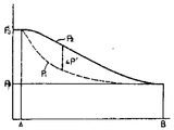
다음에 이 발명의 제2의 실시예를 제16도∼제22도에 의하여 설명한다. 상술에서 엘레멘트(6)이 홈(5)에 적절히 지지되어 있으면 상기 잇점이 있음을 알 수 있지만 그러나 장기 운전하면 엘레멘트(6)이 국부적으로 이상마모를 한다든가 홈(5)내에 함몰하는 일이 생겼다. 그래서 제10도에 표시한 빈틈(501)과 압축실(P)의 각 운전중의 압력을 측정한바, 제16도에 표시한 결과를 얻었다. 여기서는 어느 포인트(B)에서 포인트(A)까지의 빈틈(501)의 압력변동(p1) 및 그것에 대응하는 압축실(P)의 압력변동(P2)를 표시하며 (△P)는 그 차압을 표시한다. 운전조건 및 측정포인트에 의하여 다르지만 도면중(a)와 같이 압축실(P)의 압력(P2) 보다 빈틈(501)의 압력 (p1)쪽이 P 만큼 크게되는 경우가 있다. 이럴 때 엘레멘트(6)은 홈(5)에서 돌출 되어서 받침판(102)(202)와 활동하여 마모된다. 또 (b)와 같이 P2보다 P1쪽이 △P 만큼 작게되는 경우 엘레멘트(6)은 홈(5)안으로 함몰하게 된다. 그래서 압축실(P)와 빈틈(501)간에 상통부를 설치하여 균압시키는데 착상하였다.Next, the second embodiment of the present invention will be described with reference to FIGS. In the above description, it can be seen that the
제17도는 그의 단적인 예인 엘레멘트(6)의 시단부 A와 종단부 B에 있어서 홈(5)의 각각 대응하는 단부간에 도면과 같이 간격을 비교적 크게 설치해본바 제18도 같이 P1과 P2의 차압 △P는 적어졌다.FIG. 17 shows a relatively large gap between the corresponding ends of the
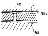
더욱 발전시켜서 제19도 및 제20도에 표시한대로 엘레멘트(6)의 측면에 축 방향으로 홈(610)을 적의 설치하여서 빈틈(501)과 실(P)과를 와권 긴쪽방향에 따라 적의 상통시킨바 제18도에 표시하는 △P의 값은 더욱 적어져 대략 균압이 되었다. 또 이같이 사양으로 장기간 운전하였던 바 전기 엘레멘트(6)의 마모나 함몰은 볼 수 없게 됐다. 이러한 균압홈은 흠(5)측에 설치해도 무방함을 말할 것도 없다.Further, as shown in FIG. 19 and FIG. 20, the
또 다른 실시예로서 제21도 및 제22도에 표시한 대로 와권긴쪽 방향에 따라 홈(5)에 절개부를 설치하여도 된다. 제23도∼제25도는 이 발명의 제 3의 실시예로서 엘레멘트(6)을 와권긴쪽 방향에 따라 분할하여 압입하고 각 엘레멘트(6)의 사이에는 간격(611)을 설치한 것이다. 이와 같이 하면은 엘레멘트(6) 1개의 길이가 짧아도 되므로 공작성의 향상도 도모할 수 있다.As another example, as shown in FIG. 21 and FIG. 22, a cutout may be provided in the
제26도는 이상 말한 균압에 의한 엘레멘트(6)의 이동방지 외에 더욱 안전성을 증대시키기 위하여 고안된 것으로서 홈(5)를 이형(異形)으로 하여 대처하려는 것이다. 제26도(a)는 홈(5)를 도면같이 테이퍼형으로 하여 엘레멘트(6)의 필요이상의 함몰을 방지하고 있다. 또 (b)는 (a)와는 역의 테이퍼로 하므로서 엘레멘트(6)의 부상(浮上)에 따른 받침판(102)와의 활동마모를 방지하려는 것이다. (c)는 홈(5)의 단면에 철(![]()
![]()
제27도 및 제28도는 이 발명의 제4의 실시예이며 제12도 내지 제13도의 조립방법에 있어서는 조립한 경우 엘레멘트(6)의 홈(5)로의 삽입이 어렵고 엘레멘트(6)양측면에 우그러짐(Burr)이 발생하는 등 문제가 있었다. 그래서 제27도에 표시하는 바와 같이 안내홈(5)을 저면(5d)의 홈폭칫수(D1)보다 상면 트인쪽의 홈폭칫수(D2)가 크게되도록 측면(5b) (5c)를 테이퍼 형상으로하여 엘레멘트의 폭칫수(D)가 (D1) < (D) < (D2)로 되도록 한바 엘레멘트(6)의 안내홈(5)로의 삽입이 용이해졌다. 또 이와같이 하여 압입 조립한 상태를 제28도(a)에 표시하며 엘레멘트(6)은 홈테이퍼부(5b) (5c)에 의하여 양측면이 변형되어 있음을 알 수 있다. 이러한 뜻에서 엘레멘트(6)의 재질은 태트라 불화 에틸렌 같은 가요성 있는 재질이 좋다. 여기서 힘의 균형을 생각해보면 아래와 같다.27 and 28 are the fourth embodiment of the present invention, and in the assembling method of FIGS. 12 to 13, when assembled, the insertion of the
즉 제28도(b)에 표시한대로 홈(5)의 테이퍼부의 한쪽(5c)의 각도를 θ, 엘레멘트(6)을 홈(5)에 압입하였을 때의 압축응력 P, 엘레멘트(6)을 낙하시키는 축방향힘을 F, F에 대향하여 엘레멘트(6)이 홈(5)의 측면(5c)에 미끄러지려고 할 때 발생하는 마찰력을 R, 엘레멘트(6)의 마찰계수를 μ로 하였을때 (5c)(5b)의 각도는 같이 θ로 할 때의 힘의 균형은 하기식이 된다.That is, as shown in Fig. 28 (b), the compressive stress P and the
F= 2Psinθ cosθ -2RcosθF = 2Psinθ cosθ -2Rcosθ
= 2Pcosθ (sinθ + μcosθ)= 2Pcosθ (sinθ + μcosθ)
여기서 상식의 좌변>우변일때 엘레멘트(6)은 함몰된다. 따라서 θ는 좌변≤우변이 되도록 결정된다. 또 좌변<우변이된 경우 엘레멘트(6)이 부상할 것이 예상되지만 이 경우 축방향간격 A는 0로 되어서 엘레멘트(6)이 상대재의 저면(101a) (201a)로 각각 밀착한 상태가 되고 보다 한층 시일효과가 기대되는 것이다.Here, the
이상과같이 이 발명에 관한 스크롤 유체기계는 각각 나선형 등의 와권측판을 받침판 면에 돌출시켜 형성한 고정스크롤 및 요동스크롤을 서로 짜맞추므로서 상기 각 와권측판 및 받침판 면에 의하여 복수의 실을 형성하고 요동스크롤을 선회시켜 상기 실에 주입된 액체를 이송·압송 내지 팽창하도록 구성한 스크롤 유체기계에 있어서 상기 양스크롤의 각 와권측판과 각각 같은 형상의 와권형상인 한쌍의 미조정용 엘레멘트와 이것을 와권축 방향에 끼워 맞추는 같은 와권형상의 안내홈을 상기 양스크롤의 와권측판의 단면에 설치하여 상기각 미조정용 엘레멘트를 그것에 대응하는 상기 각 안내홈에서 끼워맞출때 와권축방향으로 소성변형하여 상기 각 미조정용 엘레멘트를 통하여 상기 각 와권측판 단면과 이에 대응하는 받침판 저변간의 간격을 미조정할 수 있도록 스크롤의 와권형과 측판단면에 설치한 안내홈에 균등하게 미조정용 엘레멘트를 끼워넣고 상기미조정용 엘레멘트를 축방향에 소성변형시켜서 고정스크롤 및 요동스크롤의 각 와권측판 단면과 받침판 저면간의 축방향 간격의 미조정을 할 수 있어 고정스크롤, 요동스크롤등의 공작정밀도의 오차를 배제하고 실질간격이 없는 혹은 필요한 최소한의 미소간격으로 조정할 수 있고 또한 운전중 열적변형등으로 엘레멘트가 받침판에 접촉하여도 소성변형이 거듭되거나 마모하여 안정된 상태로 고정되어서 누출이 적은 신뢰성 높은간격 미조정기구를 제공할 수 있으며 그리고 스크롤의 와권형의 측판단면에 설치한 안내홈에 균등하게 미조정용 엘레멘트를 압입함으로써 상기 미조정용 엘레멘트를 통하여 고정스크롤 및 요동스크롤의 각 와권측판단면자 받침판 전면간의 축방향 간격의 미조정을 할 수 있으며 고정스크롤 요동스크롤 등의 공작정밀도의 오차를 배제하고 실질간격 없는 혹은 필요한 최소한의 미소간격으로 조정할 수 있으며 또한 미조정용 엘레멘트와 안내홈간에 축방향에 빈틈부가 있도록하여 이 빈틈부와 상기 실과를 상통시키도록 하였으므로 빈틈부와 실과의 사이는 대략 균압되므로서 운전중 실의 압력변동에 의한 미조정용 엘레멘트의 축방향으로의 이동이 방지되며 따라서 미조정용 엘레멘트에는 실질축 방향으로는 힘이 발생하지 않고 엘레멘트와 받침판간에 마찰저항이나 마모가 없으며 또한 엘레멘트가 안내부안으로 함몰하는 일 없이 안정된 상태에서 고정되고, 누출이 적은 신뢰성 높은 간격 미조정기구도 제공되며 또 안내홈이 역사다리꼴의 테이퍼형으로 되어 있으므로 운전중 실의 압력변동에 의한 미조정용 엘레멘트의 축방향밑으로의 이동이 방지되고, 따라서 미조정용 엘레멘트가 안내홈안으로 함몰되는 일없이 안정된 상태로 고정되어서 누출이 적고 신뢰성 높은 간격 미조정기구가 제공되는 것이다.As described above, the scroll fluid machine according to the present invention forms a plurality of threads by each of the spiral winding side plates and the backing plate surfaces by fitting together the fixed scroll and the swinging scroll formed by projecting the spiral winding side plates, such as spirals, onto the supporting plate surfaces. In a scroll fluid machine configured to rotate, swing, and scroll the liquid injected into the chamber, a pair of fine-tuning elements each having a spiral shape having the same shape as each spiral winding plate of both scrolls, and in the spiral winding direction. A guide groove of the same vortex shape to be fitted is provided on the end face of the vortex winding side plate of both scrolls, and the plastic element is plastically deformed in the vortex winding direction when the respective fine adjustment elements are fitted in the respective guide grooves corresponding thereto. The gap between the end surface of each spiral winding plate and the bottom of the support plate To make it possible, insert the fine adjustment element evenly into the guide groove installed on the spiral winding of the scroll and the side plate end face, and plastically deform the fine adjustment element in the axial direction so that the shaft between the end face of each spiral wound plate of the fixed scroll and rocking scroll and the bottom of the backing plate The direction gap can be fine-adjusted, eliminating errors in work precision such as fixed scroll and rocking scroll, and can be adjusted to the minimum gap without actual gap or required. Also, the element contacts the support plate due to thermal deformation during operation. The plastic deformation is repeated or worn and fixed in a stable state, so that a reliable gap fine adjustment mechanism with low leakage can be provided, and the fine adjustment element is equally inserted into the guide grooves installed on the side plate end surface of the spiral winding of the scroll. Each winding of fixed scroll and rocking scroll through fine adjustment elements Fine adjustment of the axial gap between the front side of the side plate end plate and the plate can be made without actual gaps or minimum necessary gaps without any errors in the work precision such as fixed scroll rocking scrolls, and between the fine adjustment elements and the guide grooves. Since there is a gap in the axial direction so that the gap and the seal are made to be in contact with each other, the gap between the gap and the seal is approximately equalized, thereby preventing movement of the fine adjustment element in the axial direction due to the pressure variation of the seal during operation. The fine adjustment element has no force in the direction of the real axis, no frictional resistance or abrasion between the element and the support plate, and is fixed in a stable state without recessing the element into the guide part. And the guide groove is tapered with an inverted trapezoid Therefore, the movement of the fine adjustment element under the axial direction is prevented due to the fluctuation of the seal pressure during operation, so that the fine adjustment element is fixed in a stable state without being recessed into the guide groove, so that there is little leakage and a reliable interval fine adjustment mechanism is provided. It is provided.
Claims (5)
Applications Claiming Priority (6)
| Application Number | Priority Date | Filing Date | Title |
|---|---|---|---|
| JP106306 | 1985-05-16 | ||
| JP60106306A JPS61261601A (en) | 1985-05-16 | 1985-05-16 | Scroll fluid machine |
| JP60106308A JPS61265302A (en) | 1985-05-16 | 1985-05-16 | Scroll fluid machine |
| JP60106501A JPS61265304A (en) | 1985-05-17 | 1985-05-17 | Scroll fluid machine |
| JP106308 | 1985-05-17 | ||
| JP106501 | 1992-04-24 |
Publications (2)
| Publication Number | Publication Date |
|---|---|
| KR860009238A KR860009238A (en) | 1986-12-20 |
| KR910001552B1 true KR910001552B1 (en) | 1991-03-15 |
Family
ID=27310699
Family Applications (1)
| Application Number | Title | Priority Date | Filing Date |
|---|---|---|---|
| KR1019850008593A Expired KR910001552B1 (en) | 1985-05-16 | 1985-11-16 | Scroll type fluid transfering machine |
Country Status (3)
| Country | Link |
|---|---|
| US (2) | US4740143A (en) |
| KR (1) | KR910001552B1 (en) |
| DE (1) | DE3614614C2 (en) |
Families Citing this family (24)
| Publication number | Priority date | Publication date | Assignee | Title |
|---|---|---|---|---|
| KR920008914B1 (en) * | 1985-11-27 | 1992-10-12 | 미쓰비시전기 주식회사 | Scroll fluid machine |
| JPS62126207A (en) * | 1985-11-27 | 1987-06-08 | Mitsubishi Electric Corp | Scroll hydraulic machine |
| US5094205A (en) * | 1989-10-30 | 1992-03-10 | Billheimer James C | Scroll-type engine |
| JPH03246157A (en) * | 1990-02-23 | 1991-11-01 | Toyota Motor Corp | Antiskid controlling device |
| US5116208A (en) * | 1990-08-20 | 1992-05-26 | Sundstrand Corporation | Seal rings for the roller on a rotary compressor |
| US5222882A (en) * | 1992-02-20 | 1993-06-29 | Arthur D. Little, Inc. | Tip seal supporting structure for a scroll fluid device |
| TW326243U (en) * | 1993-09-02 | 1998-02-01 | Toyoda Automatic Loom Works | Scroll type compressor |
| US5474433A (en) * | 1994-07-21 | 1995-12-12 | Industrial Technology Research Institute | Axial sealing mechanism of volute compressor |
| US5609478A (en) * | 1995-11-06 | 1997-03-11 | Alliance Compressors | Radial compliance mechanism for corotating scroll apparatus |
| US5833443A (en) * | 1996-10-30 | 1998-11-10 | Carrier Corporation | Scroll compressor with reduced separating force between fixed and orbiting scroll members |
| US5857844A (en) * | 1996-12-09 | 1999-01-12 | Carrier Corporation | Scroll compressor with reduced height orbiting scroll wrap |
| USD397531S (en) | 1997-08-13 | 1998-08-25 | Novalek, Inc. | Pet water bottle |
| EP0924429B1 (en) * | 1997-12-18 | 2003-08-13 | Mitsubishi Heavy Industries, Ltd. | Scroll compressor |
| US6585501B2 (en) * | 2000-11-06 | 2003-07-01 | Mitsubishi Heavy Industries, Ltd. | Scroll compressor sealing |
| JP2008267150A (en) * | 2007-04-16 | 2008-11-06 | Sanden Corp | Fluid machine |
| US7958862B2 (en) * | 2007-12-07 | 2011-06-14 | Secco2 Engines, Inc. | Rotary positive displacement combustor engine |
| US8006496B2 (en) | 2008-09-08 | 2011-08-30 | Secco2 Engines, Inc. | Closed loop scroll expander engine |
| GB2472637B (en) * | 2009-08-14 | 2015-11-25 | Edwards Ltd | Scroll Compressor With Plural Sealing Types |
| GB2472776B (en) | 2009-08-14 | 2015-12-02 | Edwards Ltd | Scroll pump with tip seal pockets |
| GB0914230D0 (en) | 2009-08-14 | 2009-09-30 | Edwards Ltd | Scroll pump |
| GB2489469B (en) | 2011-03-29 | 2017-10-18 | Edwards Ltd | Scroll compressor |
| JP6622527B2 (en) * | 2015-09-10 | 2019-12-18 | アネスト岩田株式会社 | Scroll fluid machinery |
| JP6098706B1 (en) * | 2015-12-28 | 2017-03-22 | ダイキン工業株式会社 | Scroll compressor |
| CN109185144B (en) * | 2018-11-01 | 2020-11-13 | 珠海格力电器股份有限公司 | Sealing structure and vortex type air compressor with same |
Family Cites Families (11)
| Publication number | Priority date | Publication date | Assignee | Title |
|---|---|---|---|---|
| US801182A (en) * | 1905-06-26 | 1905-10-03 | Leon Creux | Rotary engine. |
| US1365348A (en) * | 1918-12-11 | 1921-01-11 | Shetler Melvin | Piston-ring |
| US2925296A (en) * | 1955-07-22 | 1960-02-16 | Wellworthy Ltd | Sealing rings |
| US3994636A (en) * | 1975-03-24 | 1976-11-30 | Arthur D. Little, Inc. | Axial compliance means with radial sealing for scroll-type apparatus |
| US4199308A (en) * | 1978-10-02 | 1980-04-22 | Arthur D. Little, Inc. | Axial compliance/sealing means for improved radial sealing for scroll apparatus and scroll apparatus incorporating the same |
| CA1222986A (en) * | 1980-09-30 | 1987-06-16 | Kiyoshi Terauchi | Scroll type fluid compressor unit |
| AU551894B2 (en) * | 1981-05-11 | 1986-05-15 | Sanden Corporation | Seal for scroll member in scroll pump |
| JPS57180182U (en) * | 1981-05-11 | 1982-11-15 | ||
| DE3140512A1 (en) * | 1981-10-13 | 1983-04-21 | Fa. Jos. L. Meyer, 2990 Papenburg | Displacer machine |
| JPS59176484A (en) * | 1983-03-26 | 1984-10-05 | Mitsubishi Electric Corp | Scroll compressor |
| JPS59176485A (en) * | 1983-03-26 | 1984-10-05 | Mitsubishi Electric Corp | Scroll compressor |
-
1985
- 1985-11-16 KR KR1019850008593A patent/KR910001552B1/en not_active Expired
-
1986
- 1986-04-25 US US06/855,675 patent/US4740143A/en not_active Expired - Fee Related
- 1986-04-30 DE DE3614614A patent/DE3614614C2/en not_active Expired - Fee Related
-
1987
- 1987-12-17 US US07/134,356 patent/US4824343A/en not_active Expired - Fee Related
Also Published As
| Publication number | Publication date |
|---|---|
| DE3614614A1 (en) | 1986-11-20 |
| US4824343A (en) | 1989-04-25 |
| KR860009238A (en) | 1986-12-20 |
| US4740143A (en) | 1988-04-26 |
| DE3614614C2 (en) | 1993-12-09 |
Similar Documents
| Publication | Publication Date | Title |
|---|---|---|
| KR910001552B1 (en) | Scroll type fluid transfering machine | |
| KR900000109B1 (en) | Scroll fluid machine | |
| KR890000249B1 (en) | Scroll fluid machine | |
| AU759504B2 (en) | Positive displacement pump | |
| CN101297117B (en) | scroll compressor | |
| JPH0143514Y2 (en) | ||
| US4954057A (en) | Scroll compressor with lubricated flat driving surface | |
| US5846065A (en) | Scroll compressor with axial biasing | |
| JP3932519B2 (en) | Scroll compressor | |
| CN112654787B (en) | Radial compliance of co-rotating scroll compressor | |
| KR20090113242A (en) | Metal Powder Scroll Hub Joint | |
| CA2243744C (en) | Intermediate pressure regulating valve for a scroll machine | |
| JP3991170B2 (en) | Scroll compressor | |
| AU2016239057B2 (en) | Rotary compressor arrangement | |
| US4715796A (en) | Scroll-type fluid transferring machine with loose drive fit in crank shaft recess | |
| JPH0327721B2 (en) | ||
| JP7401664B2 (en) | Stability in co-rotating scroll compressors | |
| JP2820137B2 (en) | Scroll gas compressor | |
| JPH08232858A (en) | Scroll compressor | |
| GB2320062A (en) | Scroll compressor | |
| JPH07310682A (en) | Scroll type fluid machine | |
| JPS61265304A (en) | Scroll fluid machine | |
| JPS61265302A (en) | Scroll fluid machine | |
| EP0825331A1 (en) | Scroll fluid displacement machine | |
| JPH08270576A (en) | Scroll compressor |
Legal Events
| Date | Code | Title | Description |
|---|---|---|---|
| A201 | Request for examination | ||
| PA0109 | Patent application |
Patent event code: PA01091R01D Comment text: Patent Application Patent event date: 19851116 |
|
| PA0201 | Request for examination | ||
| PG1501 | Laying open of application | ||
| E601 | Decision to refuse application | ||
| E902 | Notification of reason for refusal | ||
| PE0601 | Decision on rejection of patent |
Patent event date: 19880901 Comment text: Decision to Refuse Application Patent event code: PE06012S01D |
|
| PE0902 | Notice of grounds for rejection |
Comment text: Notification of reason for refusal Patent event date: 19880901 Patent event code: PE09021S01D |
|
| J2X1 | Appeal (before the patent court) |
Free format text: APPEAL AGAINST DECISION TO DECLINE REFUSAL |
|
| PJ2001 | Appeal |
Appeal kind category: Appeal against decision to decline refusal Decision date: 19900731 Appeal identifier: 1988201001138 Request date: 19881226 |
|
| G160 | Decision to publish patent application | ||
| PG1605 | Publication of application before grant of patent |
Comment text: Decision on Publication of Application Patent event code: PG16051S01I Patent event date: 19910211 |
|
| E701 | Decision to grant or registration of patent right | ||
| PE0701 | Decision of registration |
Patent event code: PE07011S01D Comment text: Decision to Grant Registration Patent event date: 19910531 |
|
| GRNT | Written decision to grant | ||
| PR0701 | Registration of establishment |
Comment text: Registration of Establishment Patent event date: 19910614 Patent event code: PR07011E01D |
|
| PR1002 | Payment of registration fee |
Payment date: 19910614 End annual number: 3 Start annual number: 1 |
|
| PR1001 | Payment of annual fee |
Payment date: 19940308 Start annual number: 4 End annual number: 4 |
|
| PR1001 | Payment of annual fee |
Payment date: 19950308 Start annual number: 5 End annual number: 5 |
|
| PR1001 | Payment of annual fee |
Payment date: 19960313 Start annual number: 6 End annual number: 6 |
|
| PR1001 | Payment of annual fee |
Payment date: 19970311 Start annual number: 7 End annual number: 7 |
|
| PR1001 | Payment of annual fee |
Payment date: 19980310 Start annual number: 8 End annual number: 8 |
|
| PR1001 | Payment of annual fee |
Payment date: 19990309 Start annual number: 9 End annual number: 9 |
|
| PR1001 | Payment of annual fee |
Payment date: 20000307 Start annual number: 10 End annual number: 10 |
|
| PR1001 | Payment of annual fee |
Payment date: 20010307 Start annual number: 11 End annual number: 11 |
|
| PR1001 | Payment of annual fee |
Payment date: 20020307 Start annual number: 12 End annual number: 12 |
|
| PR1001 | Payment of annual fee |
Payment date: 20030311 Start annual number: 13 End annual number: 13 |
|
| PR1001 | Payment of annual fee |
Payment date: 20040310 Start annual number: 14 End annual number: 14 |
|
| FPAY | Annual fee payment |
Payment date: 20050309 Year of fee payment: 15 |
|
| PR1001 | Payment of annual fee |
Payment date: 20050309 Start annual number: 15 End annual number: 15 |
|
| EXPY | Expiration of term | ||
| PC1801 | Expiration of term |