KR890000249B1 - Scroll-type apparatus with gap adjustment means - Google Patents

Scroll-type apparatus with gap adjustment means Download PDF

Info

Publication number
KR890000249B1
KR890000249B1 KR1019850001513A KR850001513A KR890000249B1 KR 890000249 B1 KR890000249 B1 KR 890000249B1 KR 1019850001513 A KR1019850001513 A KR 1019850001513A KR 850001513 A KR850001513 A KR 850001513A KR 890000249 B1 KR890000249 B1 KR 890000249B1
Authority
KR
South Korea
Prior art keywords
scroll
fitting
groove
vortex
fluid machine
Prior art date
Application number
KR1019850001513A
Other languages
Korean (ko)
Other versions
KR850008391A (en
Inventor
도시유끼 나까무라
마사히로 스기하라
쓰도무 이나바
마사히꼬 오오이데
다다시 기무라
노리히데 고바야시
Original Assignee
미쓰비시 전기주식회사
카다야마히도 하지로
Priority date (The priority date is an assumption and is not a legal conclusion. Google has not performed a legal analysis and makes no representation as to the accuracy of the date listed.)
Filing date
Publication date
Application filed by 미쓰비시 전기주식회사, 카다야마히도 하지로 filed Critical 미쓰비시 전기주식회사
Publication of KR850008391A publication Critical patent/KR850008391A/en
Application granted granted Critical
Publication of KR890000249B1 publication Critical patent/KR890000249B1/en

Links

Images

Classifications

    • FMECHANICAL ENGINEERING; LIGHTING; HEATING; WEAPONS; BLASTING
    • F01MACHINES OR ENGINES IN GENERAL; ENGINE PLANTS IN GENERAL; STEAM ENGINES
    • F01CROTARY-PISTON OR OSCILLATING-PISTON MACHINES OR ENGINES
    • F01C1/00Rotary-piston machines or engines
    • F01C1/02Rotary-piston machines or engines of arcuate-engagement type, i.e. with circular translatory movement of co-operating members, each member having the same number of teeth or tooth-equivalents
    • FMECHANICAL ENGINEERING; LIGHTING; HEATING; WEAPONS; BLASTING
    • F01MACHINES OR ENGINES IN GENERAL; ENGINE PLANTS IN GENERAL; STEAM ENGINES
    • F01CROTARY-PISTON OR OSCILLATING-PISTON MACHINES OR ENGINES
    • F01C19/00Sealing arrangements in rotary-piston machines or engines
    • F01C19/08Axially-movable sealings for working fluids
    • FMECHANICAL ENGINEERING; LIGHTING; HEATING; WEAPONS; BLASTING
    • F01MACHINES OR ENGINES IN GENERAL; ENGINE PLANTS IN GENERAL; STEAM ENGINES
    • F01CROTARY-PISTON OR OSCILLATING-PISTON MACHINES OR ENGINES
    • F01C1/00Rotary-piston machines or engines
    • F01C1/02Rotary-piston machines or engines of arcuate-engagement type, i.e. with circular translatory movement of co-operating members, each member having the same number of teeth or tooth-equivalents
    • F01C1/0207Rotary-piston machines or engines of arcuate-engagement type, i.e. with circular translatory movement of co-operating members, each member having the same number of teeth or tooth-equivalents both members having co-operating elements in spiral form
    • F01C1/0215Rotary-piston machines or engines of arcuate-engagement type, i.e. with circular translatory movement of co-operating members, each member having the same number of teeth or tooth-equivalents both members having co-operating elements in spiral form where only one member is moving
    • FMECHANICAL ENGINEERING; LIGHTING; HEATING; WEAPONS; BLASTING
    • F04POSITIVE - DISPLACEMENT MACHINES FOR LIQUIDS; PUMPS FOR LIQUIDS OR ELASTIC FLUIDS
    • F04CROTARY-PISTON, OR OSCILLATING-PISTON, POSITIVE-DISPLACEMENT MACHINES FOR LIQUIDS; ROTARY-PISTON, OR OSCILLATING-PISTON, POSITIVE-DISPLACEMENT PUMPS
    • F04C2230/00Manufacture
    • F04C2230/60Assembly methods
    • FMECHANICAL ENGINEERING; LIGHTING; HEATING; WEAPONS; BLASTING
    • F04POSITIVE - DISPLACEMENT MACHINES FOR LIQUIDS; PUMPS FOR LIQUIDS OR ELASTIC FLUIDS
    • F04CROTARY-PISTON, OR OSCILLATING-PISTON, POSITIVE-DISPLACEMENT MACHINES FOR LIQUIDS; ROTARY-PISTON, OR OSCILLATING-PISTON, POSITIVE-DISPLACEMENT PUMPS
    • F04C23/00Combinations of two or more pumps, each being of rotary-piston or oscillating-piston type, specially adapted for elastic fluids; Pumping installations specially adapted for elastic fluids; Multi-stage pumps specially adapted for elastic fluids
    • F04C23/008Hermetic pumps
    • FMECHANICAL ENGINEERING; LIGHTING; HEATING; WEAPONS; BLASTING
    • F05INDEXING SCHEMES RELATING TO ENGINES OR PUMPS IN VARIOUS SUBCLASSES OF CLASSES F01-F04
    • F05BINDEXING SCHEME RELATING TO WIND, SPRING, WEIGHT, INERTIA OR LIKE MOTORS, TO MACHINES OR ENGINES FOR LIQUIDS COVERED BY SUBCLASSES F03B, F03D AND F03G
    • F05B2230/00Manufacture
    • F05B2230/60Assembly methods
    • YGENERAL TAGGING OF NEW TECHNOLOGICAL DEVELOPMENTS; GENERAL TAGGING OF CROSS-SECTIONAL TECHNOLOGIES SPANNING OVER SEVERAL SECTIONS OF THE IPC; TECHNICAL SUBJECTS COVERED BY FORMER USPC CROSS-REFERENCE ART COLLECTIONS [XRACs] AND DIGESTS
    • Y10TECHNICAL SUBJECTS COVERED BY FORMER USPC
    • Y10TTECHNICAL SUBJECTS COVERED BY FORMER US CLASSIFICATION
    • Y10T29/00Metal working
    • Y10T29/49Method of mechanical manufacture
    • Y10T29/49229Prime mover or fluid pump making
    • Y10T29/49236Fluid pump or compressor making
    • Y10T29/4924Scroll or peristaltic type

Abstract

The scroll-type apparatus is used for a compressor or a pump. The apparatus comprises a moving scroll (1), a stationary scroll (2) and gap adjustment elements (6). The scrolls have spiral wraps (101,102) integrally formed with base plates (102,202) and the elements extend beyond the top of the wraps. The scrolls are combined so that the base plates are parallel and the top of one adjustment element is closely spaced to the base plate of the other scroll.

Description

스크롤 유체기계Scroll fluid machine

제1도는 스크롤 유체기계의 작동 원리도.1 is a working principle diagram of a scroll fluid machine.

제2도는 종래예의 단면도.2 is a cross-sectional view of a conventional example.

제3도-제5도는 다른 종래예의 국부 단면도.3 to 5 are local cross-sectional views of another conventional example.

제6도는 본 발명의 한실시예에 의한 시일(seal), 미조정(微調整)조립기구를 갖춘 스크롤 압축기의 단면도6 is a cross-sectional view of a scroll compressor equipped with a seal and a fine adjustment assembly according to one embodiment of the present invention.

제7도는 상기의 조립도.7 is an assembly view of the above.

제8도-제11도는 편심부시의 구성과 작동을 설명하는 부분의 상세한 요부도.8 to 11 are detailed main parts of the section for explaining the configuration and operation of the eccentric bush.

제12도는 본 실시예를 요동스크롤에 채용한 경우의 조립사시도.12 is an assembled perspective view of the present embodiment in the case of employing the rocking scroll.

제13도-제15도는 더욱 상세한 부분 요부도.13-15 are more detailed partial main views.

제15도-제18도는 다른 조립방법을 설명하는 부분 요부도.15 to 18 are partial main parts explaining another assembling method.

제19도-제32도는 본 발명의 실시예를 설명하는 부분 요부도이다.19-32 are partial main views illustrating embodiments of the present invention.

* 도면의 주요부분에 대한 부호의 설명* Explanation of symbols for main parts of the drawings

1 : 고정스크롤 2 : 요동스크롤1: fixed scroll 2: rocking scroll

101, 201 : 와권상 측판 5 : 홈101, 201: spiral wound side plate 5: groove

6 : 미조정용엘레멘트 17 : 탄성체6: fine adjustment element 17: elastic body

20 : 가소성재(可塑性材)20: plastic material

본 발명은 공기압축기, 냉매압축기등의 압축기, 펌프, 팽창기등에 사용되는 스크롤 유체기계의 간극 미조정기구에 관한 것이다.BACKGROUND OF THE INVENTION 1. Field of the Invention The present invention relates to a gap fine adjustment mechanism of a scroll fluid machine used in compressors, pumps, expanders, and the like, such as air compressors and refrigerant compressors.

스크롤 유체기계로 알려진 유체기계의 원리는 예로부터 알려져 있으며, 압축기, 펌프, 팽창기등 여러가지에 응용되어 왔다.The principle of a fluid machine, known as a scroll fluid machine, has been known for a long time and has been applied to a variety of compressors, pumps, expanders, and the like.

제1도는 스크롤 유체기계의 기본적인 구성요소를 나타낸 것이며, 도면의 (1)은 고정스크롤, (2)는 요동스크롤, (1a)는 토출구, (p)는 압축실, 0는 고정스크롤(1)상의 정점(定點), (0')는 요동스크롤(2)위의 정점이다.1 shows the basic components of a scroll fluid machine, in which (1) is a fixed scroll, (2) is a rocking scroll, (1a) is a discharge port, (p) is a compression chamber, and 0 is a fixed scroll (1). The vertex of the phase, (0 '), is the vertex on the rocking scroll (2).

고정스크롤(1) 및 요동스크롤(2)은 각각 후술하는 대판(臺板)상에 감는 방향이 반대이며, 동일형상의 와권측판(101)(201)이 일체로 형성되고, 제1도처럼 서로 조합되어 있으며, B점부에서 와권측판(101)(201)은 서로 그 축방향의 측면에 접하고 있다.The fixed scroll (1) and the swinging scroll (2) have opposite winding directions on a large plate, which will be described later, respectively. The spiral wound side plates (101) (201) of the same shape are integrally formed, and as shown in FIG. The vortex winding side plates 101 and 201 are in contact with each other in the axial side at the point B.

이 와권측판(101)(201)의 형상은 종래부터 알려진대로 인볼류트(involute)곡선 등으로 형성되어 있다. 다음에 본 스크롤 유체기계가 압축기로서 작동하는 경우의 동작에 관하여 설명한다.The shape of the spiral winding side plates 101 and 201 is formed by an involute curve or the like as known in the art. Next, an operation when the scroll fluid machine operates as a compressor will be described.

제1도에 있어서 고정스크롤(1)은 공간에 대하여 정지하고 있으며, 요동스크롤(2)은 고정스크롤(1)과 도면처럼 조합되어 그 자세를 공간에 대하여 변화시키지를 않고 회전운전을 하여 제1도 0°, 90°, 120°, 270°처럼 운동 한다. 요동스크롤(2)의 운동에 따라서 상기 각점 B는 중심을 향하여 이동하며, 고정스크롤의 와권측판(101) 및 요동스크롤와권측판(201)사이에 형성되는 압축실(P)는 순차로 그 용적을 감소시켜, 이 압축실(P)에 포위된 기체는 압축된 토출구(1a)로부터 토출된다.In FIG. 1, the fixed scroll 1 stops with respect to the space, and the swinging scroll 2 is combined with the fixed scroll 1 as shown in the drawing to perform a rotational operation without changing its posture with respect to the space. It works like 0 °, 90 °, 120 ° and 270 °. According to the movement of the swinging scroll 2, the corner points B move toward the center, and the compression chamber P formed between the swinging scroll plate 101 and the swinging scroll and the scrolling plate 201 of the fixed scroll sequentially increases its volume. By reducing, the gas enclosed in this compression chamber P is discharged from the compressed discharge port 1a.

이 사이에 제1도 0-0'의 거리는 일정하게 유지되어 있으며, 와권측판(101)(201)의 간격을 (2), 두께를 (t)로 표시하면

Figure kpo00001
가 되어 있다.In the meantime, the distance of FIG. 1 0-0 'is kept constant.
Figure kpo00001
Has become.

(Z)는 와권측판(101)(201)의 피치(pitch)에 해당하고 있다. 또 제1도에 있어서 요동스크롤(2)을 반대방향, 즉 0°, 270°, 180°, 90°처럼 회전하면 팽창기로서 작동하는 것은 물론이다.(Z) corresponds to the pitch of the spiral winding side plates 101 and 201. In FIG. 1, when the rocking scroll 2 is rotated in the opposite direction, i.e., 0 °, 270 °, 180 °, and 90 °, of course, it operates as an expander.

이와같은 작동 원리에 따라 작동하는 스크롤 유체기계의 구체적인 구성을 제2도를 따라 설명한다.The specific configuration of a scroll fluid machine operating according to this principle of operation will be described with reference to FIG.

제2도는 스크롤 유체기계를 압축기로 응용한 경우의 하나의 종전의 예다.2 is an example of the past when a scroll fluid machine is used as a compressor.

도면중 (1)은 고정스크롤, (2)는 요동스크롤, (1a)는 토출구, (P)는 압축실, (1b)는 흡입구, (3)은 주축, (4)는 프레임이다. 또 (101)(201)는 고정스크롤(1) 및 요동스크롤(2)의 각각의 와권측판이며, (102)(202)는 고정스크롤(1) 및 요동스크롤(2)의 각각의 대판이다. 또 (A)는 와권측판(101)(201)의 단면(端面)(101a)(201a)과 이것에 각각 당접하는 상대방의 대판(202)(102)의 저면(202a)(102a)사이의 축방향의 간극이다. 여기에서 요동스크롤(2)은 대판(202)의 와권측판(201)이 형성된면과 반대면을 프레임(4)에 지지된 상태에서 고정스크롤(1)과 제1도에 보인것같은 상태로 조합되고 고정스크롤(1)은 프레임(4)에 고정된다.In the figure, (1) is a fixed scroll, (2) is a rocking scroll, (1a) is a discharge port, (P) is a compression chamber, (1b) is a suction port, (3) is a main shaft, and (4) is a frame. In addition, (101) and (201) are vortex winding side plates of the fixed scroll (1) and the swinging scroll (2), and (102, 202) are respective large plates of the fixed scroll (1) and the swinging scroll (2). Moreover, (A) is an axis | shaft between the end surface 101a, 201a of the spiral winding side plate 101, 201, and the bottom surface 202a, 102a of the base plate 202, 102 of the counterpart which contacts this, respectively. It is the gap of direction. Here, the rocking scroll 2 is combined with the surface opposite to the surface on which the vortex winding plate 201 of the base plate 202 is formed in the fixed scroll 1 and the state shown in FIG. The fixed scroll 1 is fixed to the frame 4.

주측(3)이 화살표처럼 회전을 하면 이것에 연결된 요동스크롤(2)이 운동을 시작한다. 여기에서 요동스크롤(2)은 도면에는 없지만 자전방지장치에 의하여 자전하지 않는 공전운동을 한다. 그결과 흡입구(1b)에서 피압축 유체가 흡인되며 제1도에 보인 작동원리에 의하여 압축되며 토출구(1a)에서 토출된다. 이같은 유체기계에 있어서, 경방향시일, 즉 간격 A를 지나서 와권의 경방향으로의 누설은 그 누설선의 길이가 와권의 길이방향의 길이에 상당하므로 그 유체허용 용적에 비하여 상대적으로 커서 기계의 효율에 주는 영향은 크다.When the main side 3 rotates like an arrow, the rocking scroll 2 connected to this starts a movement. Here, the rocking scroll (2) is not in the drawing, but the revolution movement does not rotate by the anti-rotation device. As a result, the compressed fluid is sucked from the suction port 1b, compressed by the operation principle shown in FIG. 1, and discharged from the discharge port 1a. In such a fluid machine, the radial seal, i.e. the leakage in the radial direction of the vortex past the distance A, is relatively larger than the permissible volume of the fluid since the length of the leak line corresponds to the longitudinal length of the vortex. The impact is great.

이 경방향을 시일하는 방법으로서는 간극(A)를 미소로하여 가령 흡입구(1b)보다 피압축제와 더불어 기름을 흡인시켜 미소간극(a)에 유막을 형성시켜서 피압축 유체의 새는 것을 방지하는 수단이 생각되지만, 이와같은 미소극간을 균일로 설치하기 위하여 고정스크롤(1), 요동스크롤(2), 프레임(4) 등의 각부분의 치수의 정밀도가 고도로 요구되며, 경우에 따라서는 조립시에 각 부품의 선택감합을 하지않으면 안된다는 등 공작성, 조립성에 문제가 있었다.As a method for sealing the radial direction, a means for preventing leakage of the fluid to be compressed by forming an oil film in the micro gap a by using a gap A as a minute to suck oil together with the compressed agent rather than the suction port 1b. Although this is considered, in order to uniformly install such microgap, the precision of the dimension of each part, such as the fixed scroll 1, the oscillating scroll 2, the frame 4, is highly required, and at the time of assembly There was a problem in workability and assembly, such as the selection and fitting of each part.

또 운전시, 토출구(1a)근방은 압축된 유체에 의하여 고온이 되는데 그 결과 미소간극(A)이상으로 국부적으로 열팽창하면 탈열(脫熱)이 되지않으므로 눌어붙는 형상이 일어난다. 따라서 열팽창량을 예정하여 미리 그 길이(A)변의 전체를 균일하게 간극을 넓게 잡지않으면 않되지만, 이렇게 하면 효과적인 유막을 형성하는데 필요한 가장 적당한 간극 이상이 되며 그 결과로서 누설이 많아져서 시일의 효과가 없는 경우가 많았다.During operation, the vicinity of the discharge port 1a becomes a high temperature by the compressed fluid. As a result, if the local thermal expansion is larger than the microgap A, no heat is released. Therefore, the amount of thermal expansion should be scheduled and the gap between the lengths (A) should be uniformly widened in advance, but this becomes more than the most suitable gap needed to form an effective oil film, and as a result, the leakage effect increases and the effect of the seal is increased. There were many cases.

한편 이러한 비접촉시일이외에, 와권측판(101)(201)의 단면에 와권길이방향을 따라 홈을 형성하고 이홈에 형성 시일재료를 감입하여 접촉시일에 의하여 누설을 방지하는 방법이 고려되어 있다.On the other hand, in addition to the non-contact seal, a method of forming a groove along the vortex length direction in the cross section of the vortex winding plate 101 and 201 and inserting a sealing material into the groove to prevent leakage by the contact seal is considered.

이와같은 방법으로서는 오래전의 것으로는 1905년의 미국특허 제80182호에 나와있으며, 또 최근의 것으로는 일본국특개소 51-11730호 등에 공개되어 있다.As such a method, a long time ago is disclosed in US Patent No. 80182 of 1905, and a recent one is disclosed in Japanese Patent Laid-Open No. 51-11730.

한예로서 일본국특개소 51-117304호에 보인것을 제3도-제5도를 따라 설명한다.As an example, what is shown in Japanese Patent Laid-Open No. 51-117304 will be explained along FIGS. 3 to 5.

즉 제3도는 고정스크롤(1)에 대판의 저면(102a)과 요동스크롤(2)의 와권측면의 단면(201a)사이의 A부 근방의 부분 단면도이며, 와권측판(201)의 단면(201a)의 와권길이 방향을 따라서 개구하는 단면이 장방형의 홈(5)를 형성하고, 이홈(5)내에 홈(5)와 같은 형상의 시일재료(51)을 감입시키고 있다.That is, FIG. 3 is a partial sectional view of the vicinity of the portion A between the bottom surface 102a of the base plate and the end surface 201a of the vortex winding side surface of the swinging scroll 2 on the fixed scroll 1, and the cross section 201a of the vortex winding plate 201. The cross section opened along the vortex winding direction of the cross section forms a rectangular groove 5, and the sealing material 51 having the same shape as the groove 5 is inserted in the groove 5.

여기서 홈(5) 측면(5b)과 시일재료(51)의 측면(51b)과의 사이에는 와권길이 방향을 따라 극간(501), 홈(5) 저면(5d)과 시일재료(51)의 하면(51d)사이에는 역시 와권길이 방향을 따라 간극(502)이 설치될 수 있도록 홈(5) 및 시일재료(6)의 치수는 규정되고, 그결과 와권측판(201)의 단면(201a)과 대판저면(102a)사이에 간극(A)가 개재하더라도 와권측판(201)으로 구획된 고압측 압축실(PH)과 저압측 압축실(PL)사이의 시일은 고압측 압축실(PH)부터 실선 화살표로 표시되도록 간극(501)(502)에 가스가 유입하며, 그결과로서 화살표 F 처럼 힘이 부하되므로 시일재료(6)은 대판저면(102a)및 홈(5)의 측면(5C)에 각각시일재료(51)의 상면 및 측면(51C)이 짓눌려 시일재료(51)가 대판저면(102a)및 홈의 측면(5C)에 밀착하여 가스의 새나옴이 방지 된다.Here, between the groove 5 side surface 5b and the side surface 51b of the sealing material 51, the lower surface of the gap 501, the bottom surface 5d of the groove 5, and the sealing material 51 along the vortex length direction. Between 51d, the dimensions of the groove 5 and the sealing material 6 are defined so that the gap 502 can also be provided along the vortex length direction, and as a result, the end face 201a of the vortex winding plate 201 and the large plate are provided. Even if the gap A is interposed between the bottom surface 102a, the seal between the high pressure side compression chamber P H and the low pressure side compression chamber P L partitioned by the spiral winding side plate 201 is the high pressure side compression chamber P H. Gas flows into the gaps 501 and 502 so as to be indicated by a solid arrow, and as a result, the force is loaded as shown by the arrow F, so that the sealing material 6 has the base surface 102a and the side surface 5C of the groove 5. The upper surface and the side surface 51C of the sealing material 51 are crushed, respectively, so that the sealing material 51 comes into close contact with the base plate surface 102a and the side surface 5C of the groove, thereby preventing the leakage of gas.

이같은 시일방법에 있어서는 와권측판 단면과 대판의 저면사이의 간극(A)를 통하여 와권의 경방향으로의 누설에 대한 시일은 효과적으로 행해지지만, 와권측판(101)(201)끼리에 의하여 점(B)로 구획된 각 압축실(P)사이에 있어서는 간극(501)(502)을 지나서 와권길이 방향으로 새기쉬운 결점이 있었다. 즉 제4도는 와권측판(101)(201)의 접점(P)근방을 상면에서본 부분 단면도다.In such a sealing method, the sealing against the leakage in the radial direction of the vortex is effectively performed through the gap A between the end surface of the vortex side plate and the bottom of the base plate, but the vortex side plate 101, 201 is separated by the point (B). Between each compression chamber P partitioned by, there existed a fault which leaked easily in the vortex length direction beyond the clearance gap 501,502. 4 is a partial sectional view of the vicinity of the contact point P of the spiral winding side plates 101 and 201 as viewed from the top.

제5도는 마찬가지로 부분단면 사시도 이지만, 고압측 압축실(PH)에서 실선화살표로 나타내듯이 가스가 간극(501)(502)를 지나서 하류측의 저압측 압축실(PL)로 새는 상태를 나타내고 있다.5 is a partial cross-sectional perspective view similarly, but shows a state where the gas leaks through the gaps 501 and 502 to the downstream low pressure side compression chamber P L as indicated by the solid arrow in the high pressure side compression chamber P H. have.

이같은 이 형식의 시일방법은 경방향에의 시일은 효과적으로 행하지만, 그 수단으로서 홈(5)와 재료(6)사이에 간극(501)(502)를 설치하지 않으면 않되므로, 그 결과로서 와권길이 방향의 누설은 필연적으로 일어나기 마련이며, 압축효율 즉 성능의 저하는 면할수가 없다.This type of sealing method effectively seals in the radial direction, but the gap 501 and 502 must be provided between the groove 5 and the material 6 as a means, and as a result, the vortex length Directional leakage inevitably occurs, and compression efficiency, i.e., performance deterioration, cannot be avoided.

특히 공작 정밀도에 의한 간극(501)(502)의 치수는 불균형(개개제품 사이의 오차)는 간극(501)(502)을 통과하는 누설의 증대나 시일재료(51)의 추종성 자체의 저하에 의한 경방향으로의 누설의 증대가 생길 가능성이 있다.In particular, the dimensions of the gaps 501 and 502 due to the work precision are unbalanced (error between individual products) due to the increase in leakage passing through the gaps 501 and 502 or the deterioration of the followability of the sealing material 51 itself. There is a possibility of an increase in leakage in the radial direction.

다시 시일재료(51)의 상면(51a)은 가스로 말미암아 대판 저면(102a)에 눌려서 접동을 하므로 이 부분의 접동손실이나 마모도 무시할 수는 없다.Again, the upper surface 51a of the sealing material 51 is pressed by the base plate bottom 102a by gas to allow sliding, so that the sliding loss and wear of this portion cannot be ignored.

이같이 종래의 시일방법은 공작정밀도가 성능에 미치는 영향이나 신뢰성의 점등에서 문제가 있었다. 본 발명은 상술한 결점을 제거하려고 행해진 것이며, 구조가 간단하며 조립성이 쉽고 또 공작이 정밀도나 운전중의 열변형 등도 허용가능하며, 운전중의 누설을 효과적으로 방지하여 높은 효율과 신뢰성이 높은 스크롤 유체기계의 조립 미조정 기구를 제공하기를 목적으로 하고 있다.Thus, the conventional sealing method has a problem in the effect of work precision on the performance, or lighting of reliability. The present invention has been made to eliminate the above-mentioned shortcomings, and the structure is simple, the assembly is easy, the precision of the work and the heat deformation during the operation are also acceptable, and effectively prevent the leakage during the operation, high efficiency and reliable scroll An object of the present invention is to provide an assembly adjustment mechanism for a fluid machine.

이래에, 본 발명의 한실시예를 제6도-제17도를 따라 설명한다.In the following, an embodiment of the present invention will be described with reference to Figs.

제6도는 스크롤 압축기를 전밀폐형 냉매 압축기에 응용한 경우의 구체적인 한실시예다.Figure 6 is a specific embodiment when the scroll compressor is applied to the hermetic refrigerant compressor.

도면중(1)은 고정스크롤, (2)는 요동스크롤, (1b)는 고정스크롤(1)의 중앙부에 파인 토출구, (1P)는 고정스크롤(1)의 주벽부(103)에 형성된 흡입구, (P)는 압축실이다. 또 고정스크롤(1)은 원판형의 대판(102)과 이 대판(102)에 일체로 형성된 와권형 측판(101)으로 구성되고, 요동스크롤(2)도 마찬가지로 원판형의 대판(202)에 일체로 형성된 와권형 측판(201)으로 형성되고, 이두 스크롤(1)(2)이 서로 맞물려져서 대판(102)(202)와 와권형 측판(101)(102)으로 감싸인 압축실(P)가 형성되어 있다.In the drawing, (1) is a fixed scroll, (2) is a rocking scroll, (1b) is a discharge port in the center of the fixed scroll (1), (1P) is a suction port formed in the main wall portion 103 of the fixed scroll (1), (P) is a compression chamber. The fixed scroll 1 is composed of a disc-shaped base plate 102 and a spiral wound side plate 101 formed integrally with the base plate 102, and the swinging scroll 2 is similarly integrated with a disc-shaped base plate 202. Compression chamber P formed of a spiral wound side plate 201, and the bilateral scrolls 1, 2 are engaged with each other and wrapped with a large plate 102, 202 and a spiral wound side plate 101, 102, Formed.

이 압축실(P)는 복수개로 형성되고 그중 가장 압력이 센 중앙부의 압력실이 토출구(1a)에 연통하도록 구성되어 있다. 상기 와권형 측판(101)(201)의 각 단면(101a)(201a)에는 각각 와권 길이방향을 따라서 더우기 와권방향의 내단부 및 외단부를 남겨놓고 가이드부인 홈(5)이 각각 형성되고 이들각홈(5)에는 미조정용 엘레멘트(6)가 각각 감합되어 있다. 이 엘레멘트(6)는 홈(5)에 가이드되어 홈(5)에 상기 엘레멘트(6)의 양측면의 와권길이 방향으로 완전히 밀착 상태가 되도록 압입되어 있다.The compression chamber P is formed in plural, and the pressure chamber in the center of which the pressure is highest is communicated with the discharge port 1a. In each end surface 101a, 201a of the spiral winding side plate 101, 201, the groove | channel 5 which is the guide part is left, respectively, leaving the inner end and the outer end of the spiral winding direction further along the spiral winding length direction, respectively, and these groove | channels ( 5) is fitted with the fine adjustment elements 6, respectively. The element 6 is guided to the groove 5 and press-fitted into the groove 5 so as to be in close contact with each other in the vortex length direction of both sides of the element 6.

또, (3)은 주축, (301)은 와권형측판(101)(201)이 마모하여도 이들 양측판(101)(201)의 측면이 항상(B)부에서 접촉하도록 요동스크롤(2)에 압력을 가하는 편심부시, (40)은 외주부면 형상이 고정스크롤(1)과 거의 같으며 더우기 최대외경이 고정스크롤(1)과 동일한 상부 프레임, (41)은 외주면의 형상이 고정스크롤(1)과 거의 같으며, 더우기 최대외경이 상부프레임(40)보다 큰 하부프레임, (401)은 올덤이음, (402)는 압축실(P)의 압력 및 요동스크롤(2)의 자중을 받는 항상의 상부스러스트 베어링, (411)은 주축(3)의 자중과 주축(3)에 걸리는 다른 스러스트 하중을 받는 환상의 하부스러스트베어링, (403)은 주축(3)의 래디얼(radial)하중을 그상부에서 받는 상부메인 베어링이며, 이 실시예에서는 베어링메털을 사용하고 있다.In addition, (3) is the main shaft, (301) is the swinging scroll (2) so that the side surfaces of both side plates (101, 201) are always in contact with the (B) part even if the vortex winding side plates (101, 201) wear. The eccentric bush to apply pressure to the upper frame 40 is almost the same as the fixed scroll (1) and the outer frame has the same maximum outer diameter as the fixed scroll (1), (41) is the fixed scroll (1) In addition, the lower outer frame of which the maximum outer diameter is larger than the upper frame 40, 401 is Oldham, 402 is the pressure of the compression chamber P and the weight of the swinging scroll 2 at all times. The upper thrust bearing, 411 is an annular lower thrust bearing subjected to the self-weight of the spindle 3 and other thrust loads on the spindle 3, and 403 the radial load of the spindle 3 above it. It is a receiving main main bearing, and bearing metal is used in this embodiment.

(412)는 주축(3)의 래디얼 하중을 그 중간부에서 받는 하부메인베어링이며 이 실시예에서는 베어링메털을 사용하고 있다. 요동스크롤(2)의 대판(202)의 배면(202b)중심부에는 축심이 대판(202)의 배면 (202b)에 대하여 수직이며 주축(3)의 축심에 대하여 수직이며, 주축(3)의 축심에 대하여는 팽행인축(203)이 일체로 형성되어 있으며, 또 주축(3)의 상단면에는 주축(3)의 축심(회전중심)에 평행인 축심을 지닌 편심공(3a)이 형성되어 있으며, 이 편심공(3a)에 회전자재로 편심부시(301)가 감입되어 있다.Reference numeral 412 denotes a lower main bearing which receives a radial load of the main shaft 3 at its middle part, and a bearing metal is used in this embodiment. At the center of the back surface 202b of the base plate 202 of the swinging scroll 2, the shaft center is perpendicular to the back surface 202b of the base plate 202, perpendicular to the axis center of the main shaft 3, The axial axis 203 is integrally formed, and an eccentric hole 3a having an axial center parallel to the axial center (rotational center) of the main shaft 3 is formed on the upper end surface of the main shaft 3. The eccentric bush 301 is inserted into the eccentric hole 3a as a rotating material.

이 편심부시(301)는 그 외주에 대하여 편심하고 축심이 주축(3)의 축심과 평행인 편심공(301a)이 있으며, 이 편심공(301a)에는 상기 축(203)이 회전자재로 감입되어 있다. 주축(3)는 상부프레임(40)에 배설된 상부메인베어링(408), 하부프레임(41)에 배설된 하부스러트베어링(411)및 하부메인베어링(412)에 의하여 지지되어 있으며, 상부프레임(40), 하부프레임(41)은 삽구(揷口)이음 감합부등으로 상부메인베어링(403), 하부메인베어링(412)이 서로 동십이 되도록 조합되어 있다.The eccentric bush 301 has an eccentric hole 301a which is eccentric with respect to its outer circumference and whose axial center is parallel to the axial center of the main shaft 3, and the shaft 203 is inserted into the eccentric hole 301a by rotating material. have. The main shaft 3 is supported by an upper main bearing 408 disposed on the upper frame 40, a lower thrust bearing 411 and a lower main bearing 412 disposed on the lower frame 41, and an upper frame. 40, the lower frame 41 is combined so that the upper main bearing 403 and the lower main bearing 412 are equal to each other by the insertion joint fitting part or the like.

또 상부메인베어링(403)과 상부스러스트베어링(402)과는 동심이며 상부메인베어링(403)의 축심과, 상부스러스트베어링(402)의 베어링면(402a)은 수직이므로 주축(3)은 그 축심이 상부스러스트베어링(402)의 축심에 대하여 동심이 되고, 또 상부스러스트베어링(402)의 베어링면(402a)에 대하여 수직으로 유지된다.In addition, since the main main bearing 403 and the upper thrust bearing 402 are concentric and the axial center of the upper main bearing 403 and the bearing surface 402a of the upper thrust bearing 402 are vertical, the main shaft 3 is the axial center thereof. The upper thrust bearing 402 is concentric with the shaft center, and is held perpendicular to the bearing surface 402a of the upper thrust bearing 402.

또 요동스크롤(2)는 그 대판(202)의 배면(202b)이며 상기 상부스러스트베어링(402)의 베어링면(402a)에게 지지되어 있으므로 요동스크롤(2)의 대판(202)는 주축(3)에 대하여 수직자세로 유지된다.Moreover, since the rocking scroll 2 is the back surface 202b of the base plate 202, and is supported by the bearing surface 402a of the said upper thrust bearing 402, the base plate 202 of the rocking scroll 2 is the main shaft 3 It is held in a vertical position with respect to.

올덤이음(401)은 요동스크롤(2)의 자전을 방지하고 요동스크롤(2)이 주축(3)의 축심의 주위에 공전운동만을 하도록 하기위한 축이음 수단이며, 요동스크롤(2)의 대판(202)과 상부프레임(40)과의 사이에 배설되어 있다.Oldham joint 401 is a shaft joint means for preventing the rotation of the swinging scroll (2) and the swinging scroll (2) is only an orbital movement around the axis of the main shaft (3), the base of the swinging scroll (2) It is arrange | positioned between 202 and the upper frame 40. As shown in FIG.

상기 각부분 기구의 부품이 상기와 같은 상대관계로 조립된뒤 고정스크롤(1) 및 요동스크롤(2)의 각홈(5)에 각각 미조정용 엘레멘트(6)가 각홈(5)보다 크게 돌출한 상태로 장착된 상부프레임(40), 하부프레임(41), 고정스크롤(1)과는 고정스크롤(1)의 주벽부(103)와 상부프레임(40)를 관통하여 선단의 나사부(42a)가 하부프레임(41)에만 나합하는 복수개의 볼트(42)에 의하여 같이 조여진다.After the parts of the respective mechanisms are assembled in a relative relationship as described above, the fine adjustment elements 6 protrude more than the angular grooves 5 in the angular grooves 5 of the fixed scroll 1 and the swinging scroll 2, respectively. The upper frame 40, the lower frame 41, and the fixed scroll (1) mounted through the circumferential wall portion 103 and the upper frame 40 of the fixed scroll (1) through the threaded portion (42a) of the lower end It is tightened together by a plurality of bolts 42 screwed to the frame 41 only.

이 상태를 제7도에 보인다.This state is shown in FIG.

여기서 고정스크롤(1)을 주벽부(103)의 하면(103a)에서 상부프레임(40)의 외주부 상면에 형성된 설치면(40a)에 고정되는데 상부프레임(40)의 설치면(40a)은 상부스러스트베어링(402)의 베어링면(402a)과 평행이며, 요동스크롤(2)의 대판(202)의 배면(202b)과 이와 반대면인 저면 및 와권측판(201)의 단면(201a)은 각각 평행이며, 또 고정스크롤(1)의 주벽부하면(1082)와 와권측판(101)의 단면(101a)은 동일면상에 있으며, 상기 단면(101a)과 대판(102)의 저면(102a)은 평행이므로 고정스크롤(1)의 와권측판단면(101a)과 요동스크롤(2)의 대판저면(202a)및 요동스크롤(2)의 와권측판단면(201a)과 고정스크롤(1)의 대판저면(102a)의 사이는 각각 평행으로 유지된다.Here, the fixed scroll (1) is fixed to the mounting surface (40a) formed on the upper surface of the outer peripheral portion of the upper frame 40 from the lower surface (103a) of the main wall portion 103, the mounting surface (40a) of the upper frame 40 is the upper thrust Parallel to the bearing surface 402a of the bearing 402, the rear surface 202b of the base plate 202 of the rocking scroll 2 and the end surface 201a of the bottom surface and the vortex winding side plate 201 opposite to each other are parallel to each other. In addition, the end surface 1082 of the circumferential wall portion 1082 of the fixed scroll 1 and the end surface 101a of the vortex winding side plate 101 are on the same plane, and the end surface 101a and the bottom surface 102a of the base plate 102 are parallel to each other. Between the vortex winding end surface 101a of the scroll 1 and the large plate bottom surface 202a of the rocking scroll 2, and the vortex winding end surface 201a of the rocking scroll 2, and the base plate 102a of the fixed scroll 1, respectively. Are kept in parallel, respectively.

이때문에 상기 각엘레멘트(6)는 각각 고정스크롤(1)의 대판저면(102a), 요동스크롤(2)의 대판저면(202a)때문에 눌려서 균일하게 상기홈(5)안에 압입된다.For this reason, the respective elements 6 are pressed by the large plate bottom surface 102a of the fixed scroll 1 and the large plate bottom surface 202a of the rocking scroll 2, respectively, and are uniformly pressed into the grooves 5.

그리고 상기 고정스크롤(1)이 상기프레임(40)을 거쳐서 프레임(41)에 볼트(42)로 같이 조여진 상태에 있어서 상기 고정스크롤(1)의 와권측판단면(101a)과 요동스크롤(2)의 대판저면(202a)및 요동스크롤(2)의 와권측판의 단면(201a)과 고정스크롤(1)의 대판저면(102a)사이에는 균일하게 미소간극(a)이 형성되므로 이 미소간극(A)만 각홈(5)부터 균일하게 돌출상태가 되기까지 상기 각엘레멘트(6)를 상기 각홈(5)안에 압입된 정도에서 멎는다.Then, the fixed scroll (1) of the vortex winding side surface 101a and the swinging scroll (2) of the fixed scroll (1) in the state that is fastened together with the bolt 42 to the frame 41 via the frame (40) Since only a small gap A is formed uniformly between the end face 201a of the large plate bottom surface 202a and the vortex winding side plate of the swinging scroll 2, and the base plate bottom surface 102a of the fixed scroll 1, only this minute gap A is formed. The angular elements 6 are squeezed from the angular grooves 5 to the uniformly projected state at the degree of being pressed into the angular grooves 5.

그결과 각와권측단면(101a)(201a)과 상대방의 각대판 저면(202a)(102a)사이는 상기 엘레멘트(6)를 거쳐서 실질간극이 없어진다.As a result, there is no substantial gap between the angle and winding side surfaces 101a and 201a and the counterpart bottom surface 202a and 102a of the counterpart via the element 6.

다음에 제6도에 있어서, 주축(3)을 회전시키는 모터의 지지는 모터의 로터(70)가, 주축(3)에 수축끼워맞추기등으로 고정되며 상기로터(70)와 적당한 에어갭등을 확보조정하면서 모터의 스테이터(71)가 하부프레임(41)에 볼트등으로 고착되어 있다.Next, in FIG. 6, the support of the motor which rotates the main shaft 3 is fixed to the rotor 70 of the motor by shrinkage fitting or the like to the main shaft 3, so that the rotor 70 and the appropriate air gap are fixed. The stator 71 of the motor is fixed to the lower frame 41 with bolts or the like while securely adjusting.

상기 각기구부품을 상기처럼 상대관계로 조립한 기구부품(8), 즉 고정스크롤(1), 요동스크롤(2), 상부프레임(40), 하부프레임(41), 주축(3), 로터(70), 스테이터(71)등의 조립품은 밀폐용기인 쉘(shell)(9)에 수납되어 있다.The mechanical parts 8 assembled with the respective mechanical parts in a relative relationship as described above, that is, the fixed scroll 1, the swinging scroll 2, the upper frame 40, the lower frame 41, the main shaft 3, and the rotor ( 70) Assembled products, such as the stator 71, are accommodated in the shell 9 which is a sealed container.

여기서 쉘(9)는 윗뚜껑(901), 중간원통부(902), 밑뚜껑(903)으로 3분할되고, 기구부분(8)은 하부프레임은 하부프레임(41)외주부에 있어서 중간원통부(902)에 수축끼워맞춤이나 점용접등으로 고정되고 윗뚜껑(901), 밑뚜껑(903)은 상기 중간원통부(902) 양단면에서 도면처럼 중간원통부(902)의 외주부를 덮듯이 끼워맞추어져서 이들 감합부를 용접밀봉하고 있다.Here, the shell 9 is divided into three parts: an upper lid 901, an intermediate cylindrical portion 902, and a lower lid 903, and the mechanism portion 8 has a lower cylindrical portion at an outer circumferential portion of the lower frame 41. 902 is fixed by shrink fit or spot welding, and the upper lid 901 and the lower lid 903 are fitted to cover the outer circumference of the intermediate cylindrical portion 902 as shown in the both ends of the intermediate cylindrical portion 902. The fittings are welded and sealed.

(904)는 셀중간 원통부의 주벽에 용접등에 의하여 접속되고 쉘(9)의 내부공간(9a)에 개구하는 흡입관, (905)는 쉘의 윗뚜껑(901)의 중앙부를 관통하여 이 중앙부에 기밀하게 접속되고 다시 고정스크롤(1)의 토출구(1a)에 연통하도록 연장된 토출관, (906)은 쉘의 윗뚜껑(901)에 용접되고 도면에 없는 리드선으로 모터의 스테이터(71)와 전기적으로 접속된 밀봉단자, (907)은 쉘(9)의 바닥부에 고인 윤활유다.904 is a suction pipe connected to the circumferential wall of the cell intermediate cylinder by welding or the like and opened in the inner space 9a of the shell 9, and 905 penetrates through the central portion of the upper lid 901 of the shell and is airtight in this central portion. The discharge pipe, 906, which is connected to the discharge port 1a of the fixed scroll 1 and is connected to the discharge port 1a of the fixed scroll 1, is welded to the upper lid 901 of the shell and is electrically connected to the stator 71 of the motor by a lead wire not shown in the drawing. The connected sealing terminal 907 is lubricating oil accumulated at the bottom of the shell 9.

여기에서 주축(3)의 하단부는 윤활유(907)속에 담가져 있다. 또 상기 토출관(905)과 토출구(1a)의 접합부는 0링등으로 시일되어 있다.Here, the lower end of the main shaft 3 is immersed in the lubricating oil 907. The joint between the discharge tube 905 and the discharge port 1a is sealed with a 0 ring or the like.

주축(3)에는 주축(3) 하단부에서 상단부로 형성된 편심공(3a)까지 관통한 편심급유공(3b)이 형성되어 베어링 각부로 급유되도록 되어있다.The main shaft 3 is provided with an eccentric oil supply hole 3b which penetrates from the lower end of the main shaft 3 to the eccentric hole 3a formed at the upper end, and is lubricated to each bearing part.

이같이 구성된 스크롤 압축기의 동작을 다음에 설명한다. 밀봉단자(906)를 거쳐 모터의 스테이터(71)에 통전하면 모터의 로터(70)는 토오크를 발생하고 주축(3)과 더불어 회전한다.The operation of the scroll compressor thus configured will be described next. When the stator 71 of the motor is energized via the sealing terminal 906, the rotor 70 of the motor generates torque and rotates together with the main shaft 3.

주축(3)이 회전을 시작하면 주축(3)의 편심공(3a)에 감입된 편심부시(301)를 거쳐 요동스크롤(2)의 축(203)에 주축(3)의 회전력이 전달되어 요동스크롤(2)은 올덤이음(402)에 가이드되어 자전하는 일없이, 주축(3)의 축심을 중심으로하는 공전운동을 하여 제1도를 보다시피 상술한대로 압축작용이 압축실(P)에서 행해진다.When the spindle 3 starts to rotate, the rotational force of the spindle 3 is transmitted to the shaft 203 of the swinging scroll 2 via the eccentric bush 301 penetrated by the eccentric hole 3a of the spindle 3. The scroll 2 is guided to the Oldham joint 402 to perform an orbital movement about the shaft center of the main shaft 3 without rotating, so that the compression is performed in the compression chamber P as described above with reference to FIG. All.

이때 와권형 측판(101)(201)의 단면(101a)(201a)과, 이들에 대면하는 대판(202)(102)의 저면(202a), (102a)사이의 미소간극(A)를 메우도록 홈(5)에 감입된 엘레멘트(6)가 대판의 저면(202a)(102a)방면으로 실질 간극이 없는 상태로 균일하게 상기 단면(101a)(201a)에서 돌출해 있으므로 상기 미소간극(A)을 통하여 와권의 경방향, 즉 상대적으로 고압의 압축실에서 저압의 압축실로 압축냉매가스의 누설이 생기는 것을 방지한다.At this time, the micro-gaps A between the end surfaces 101a and 201a of the spiral winding side plates 101 and 201 and the bottom surfaces 202a and 102a of the base plates 202 and 102 facing them are filled. Since the element 6 penetrated into the groove 5 protrudes uniformly from the end surfaces 101a and 201a without a substantial gap toward the bottom surfaces 202a and 102a of the base plate, the microgap A is removed. This prevents the leakage of compressed refrigerant gas from the radial direction of the spiral winding, that is, from the relatively high pressure compression chamber to the low pressure compression chamber.

또 와권형측판(101)(201)의 측면끼리는 요동스크롤(2)이 편심회전운동을 하므로 생기는 원심력등을 이용하여 편심부시(301)을 요동스크롤(2)의 축(203)의 주위에 요동시켜서 주축(3)의 축심에 대한 요동스크롤(2)의 편심량을 가변하게하므로 와권형측판(101)(201)의 측면끼리가 (B)부에서 당접되고, 상기 상대적으로 고압의 압축실에서 저압의 압축실로의 압축냉매의 새나옴이 와권형측판(101)(201)의 측면사이를 지나서 와권방향에서 생기는 것이 방지된다.In addition, the eccentric bushes 301 are oscillated around the shaft 203 of the oscillating scroll 2 by using centrifugal force or the like caused by the oscillating scroll 2 eccentric rotation movement between the side surfaces of the spiral winding side plates 101 and 201. By varying the amount of eccentricity of the swinging scroll 2 with respect to the shaft center of the main shaft 3, the side surfaces of the spiral winding side plates 101 and 201 are abutted in the (B) portion, and the low pressure is increased in the relatively high pressure compression chamber. The leakage of compressed refrigerant into the compression chamber of the cross section between the side surfaces of the spiral winding side plates 101 and 201 is prevented from occurring in the spiral winding direction.

이같이하여 압축시의 새나옴은 거의 방지되고 압축효율이 높은 운전을 할수가 있다.In this way, leakage of the compression is almost prevented and it is possible to operate with high compression efficiency.

다음에 냉매가스의 흐름에 관하여 설명한다.Next, the flow of the refrigerant gas will be described.

증발기(도면에는 없음)에서의 흡입냉매는 흡입관(904)에서 쉘안의 공간(9a)에 유입하여 모터로터(70), 모터스테이터(71)등을 냉각시킴과 더불어 도면에는 없는 하부프레임(41)의 외주부에 설치된 흡입통로를 통과하여 흡입구(1b)로부터 흡입되어 압축실(P)에 감싸여 압축된뒤 고압냉매가스가 되고 토출구(1a)를 지나서 토출관(905)에서 쉘(9)밖으로 배출되어 응축기(도면에는 없음)에 이르른다.The suction refrigerant in the evaporator (not shown) flows into the space 9a in the shell from the suction pipe 904 to cool the motor rotor 70, the motor stator 71, and the like, and the lower frame 41 not shown in the drawing. After passing through the suction passage installed in the outer peripheral portion of the suction inlet (1b) is wrapped in the compression chamber (P) is compressed and becomes a high-pressure refrigerant gas and discharged through the discharge port (1a) out of the shell (9) out of the shell (9) To the condenser (not shown).

다음에 급유계에 관하여 설명한다.Next, the oil supply system will be described.

쉘(9)의 하부에 고인 윤활유(907)은 주축(3)의 회전으로 생기는 원심펌프 작용으로 편심급유공(3b)를 지나서 편심공(3a)으로 길어올려져 편심부시(301)로 급유된다. 주축(3), 편심부시(301)에 설치된 기름구멍, 기름홈(도면에는 없음)등으로부터 상부스러스트베이링(402), 하부스러스트베어링(411), 상부메인베어링(403), 하부메인베어링(412), 또올덤이음(401)을 윤활한뒤, 일부는 압축실(P)로 흡입냉매가스와 더불어 흡입되어 압축부의 시일및 윤활에 사용되어 토출관(5)에서 배출되어 응축기, 증발기(도면에는 없음)을 통과하여 다시 흡입관(904)에서 쉘(9)안으로 되돌아오지만, 매탄은 상부프레임(40), 하부프레임(41)에 각각 설치된 반유공(40b)(41a)를 지나 쉘(9)의 하부로 흘러내려 되돌아간다.The lubricating oil 907 accumulated in the lower part of the shell 9 is extended to the eccentric hole 3a through the eccentric oil supply hole 3b by the centrifugal pump action generated by the rotation of the main shaft 3, and is lubricated by the eccentric bush 301. . The upper thrust bearing 402, the lower thrust bearing 411, the upper main bearing 403, the lower main bearing from the main shaft 3, the oil hole installed in the eccentric bush 301, and the oil groove (not shown). 412, and after lubricating the old joint 401, a part is sucked together with the suction refrigerant gas into the compression chamber (P) and used for sealing and lubrication of the compression unit and is discharged from the discharge pipe (5) to condenser and evaporator (drawings) Is returned to the shell 9 from the suction pipe 904, but the methane passes through the semi-oil holes 40b and 41a respectively installed in the upper frame 40 and the lower frame 41, respectively. Flow back to the bottom of the.

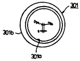
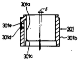
제8도는 주축(3)의 편심공(3a)에 삽입되는 편심부시(301)의 구성을 상세히 보인 도면이며, (ab)는 상면도, (b)는 측면단면도, (c)는 하면도다.8 is a view showing in detail the configuration of the eccentric bush 301 inserted into the eccentric hole 3a of the main shaft 3, (ab) is a top view, (b) is a side cross-sectional view, and (c) is a bottom view.

(301b)는 편심부시의 외주부이며, (OBo)는 그중심이다. (301a)는 편심부시의 내주면이며 (OBi)는 그중심이다. 중심(OBi)는 중심(OBo)에 대하여

Figure kpo00002
만큼 편심되고 있다. (301c)는 하단이 편심부시 하단면에 개구하여 상단부에는 편심부시상단면에 개구하지 않도록 닫은 상태로 형성된 세로방향으로 연재하는 기름홈에서 상기 내주면(301a)에 연접해 있다.Reference numeral 301b is an outer periphery of the eccentric bush, and OBo is the center thereof. 301a is the inner circumferential surface of the eccentric bush and OBi is the center thereof. Center OBi is with respect to center OBo
Figure kpo00002
As much as it is eccentric. 301c is connected to the inner circumferential surface 301a in a longitudinally extending oil groove formed so that the lower end is opened to the eccentric bush lower end surface and the upper end is closed so as not to open to the eccentric bush upper end face.

(301d)는 상기 기름홈(301c)과 외주면부(301b)를 연통하기위한 기름구멍, (301e)는 상기 외주면부(301b)에 설치된 절결부이며, 상기 기름구멍(301d)의 경방향의 외단이 절결부에 개구하고 있다.301d is an oil hole for communicating the oil groove 301c and the outer circumferential surface portion 301b, and 301e is a cutout portion provided in the outer circumferential surface portion 301b, and has an outer end in the radial direction of the oil hole 301d. It is open to this cutout part.

(301f)는 편심부시(301)의 두꺼운 부분에서 편심부시의 하단면에 뚫린 코킹용 구멍이다. 또 편심부시(301)은 알루미늄합금, 연청동등의 베어링재료로 만들어진다.301f is a caulking hole drilled in the lower surface of the eccentric bush in the thick portion of the eccentric bush 301. The eccentric bush 301 is made of a bearing material such as aluminum alloy or lead bronze.

제9도는 이같은 편심부시(301)를 주축(3)에 장착할때의 조립순서를 설명하기위한 사시도다.9 is a perspective view for explaining the assembling procedure when the eccentric bush 301 is mounted on the main shaft 3.

제8도에서 우선 주축(3)의 편심공(3a)의 바닥의 핀구멍(31)에 평면형상이 c형이며 거의 통(筒)모양인 스프링핀(32)를 감합한뒤 이스프링핀(32)에 편심부시(301)의 하부의 코킹용구멍(301f)이 맞도록 편심부시(301)을 편심공(3a)에 감입한다.In Fig. 8, first, the spring pins 32 having a c shape and a substantially cylindrical shape are fitted to the pin holes 31 at the bottom of the eccentric hole 3a of the main shaft 3, and then the spring pins ( The eccentric bush 301 is inserted into the eccentric hole 3a so that the caulking hole 301f in the lower part of the eccentric bush 301 fits into 32.

코킹용 구멍(301f)에 스핀링핀(32)이 감입하여 편심부시(301)의 하단면이 편심공(3a)의 저면에 당접한 상태로 스냅링(snap-ring)(33)을 편심공(3a)의 측면 원주방향에 형성된 스냅링홈(34)에 끼운다. 스냅링(33)은 가는 피아노선등의 탄성선상을 c형으로 형성한 것이다.The spin ring pin 32 is inserted into the caulking hole 301f so that the snap-ring 33 is eccentric with the bottom surface of the eccentric bush 301 abutting against the bottom surface of the eccentric hole 3a. Insert into the snap ring groove 34 formed in the circumferential direction of the side. The snap ring 33 is formed in a c-shaped elastic line such as a thin piano wire.

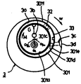
제10도는 편심부시(301)를 주축(3)에 짜넣은 상태를 나타낸 도면이며, 이 제9도의 (Os)는 주축(3)의 축심, 즉 회전중심이며, 이중심(Os)과 상기 편심부시의 내주면(301a)의 중심(OBi)과를 잇는 직선과, 상기 중심(OBi)과 상기 편심부시의 외주면(301b)의 중심과를 잇는 직선이 거의 직각을 이루는 위치에 상기중심(OBo)가 위치하도록 스프링핀(32)의 위치는 결정되어 있다. 코킹구멍(301f)의 경은 스프링핀(32)의 경보다 크게 마련되어 편심부시(301)가 주(周)방향에 어느 정도 움직일 수 있도록 되어있다.FIG. 10 is a view showing a state in which the eccentric bush 301 is incorporated into the main shaft 3, and (9) of FIG. 9 is the axis of the main shaft 3, that is, the center of rotation, and the double core Os and the eccentric bush The center OBo is positioned at a position where a straight line connecting the center OBi of the inner circumferential surface 301a of the and an straight line connecting the center OBi and the center of the outer circumferential surface 301b of the eccentric bush are substantially perpendicular to each other. The position of the spring pin 32 is determined. The diameter of the caulking hole 301f is larger than the diameter of the spring pin 32 so that the eccentric bush 301 can move to some extent in the circumferential direction.

또 편심부시(301)의 기름구멍(301d)과 주축(3)의 대경부의 반경방향으로 뚫린 기름구멍(3c)이 편심부시(301)의 회동에 의하여도 항상 연통하도록 절결부(301e)는 주방향으로 소정의 길이가 형성되어 있다.In addition, the cutout portion 301e is mainly connected so that the oil hole 301d of the eccentric bush 301 and the oil hole 3c drilled in the radial direction of the large diameter portion of the main shaft 3 always communicate with each other even by the rotation of the eccentric bush 301. The predetermined length is formed in the direction.

상기 기름구멍(3c)은 다시 주축(3)대경부의 외주면의 축방향으로 설치된 기름홈(3d)에 연통되어 있다. 요동스크롤(2)의 요동축(203)은 편심부시(301)안에 요동축(203)의 외주면이 내주면(301a)과 접동이 가능하도록 감입되므로 상기 편심부시의 내주면(301a)의 중심(OBi)는 요동중심, 즉 요동스크롤(2)의 중심(重心)과 일치하고 있다.The oil hole 3c again communicates with an oil groove 3d provided in the axial direction of the outer circumferential surface of the large diameter portion of the main shaft 3. The oscillating shaft 203 of the oscillating scroll 2 is inserted into the eccentric bush 301 so that the outer circumferential surface of the oscillating shaft 203 can slide with the inner circumferential surface 301a, so that the center OBi of the inner circumferential surface 301a of the eccentric bushing is allowed to slide. Is coincident with the oscillation center, that is, the center of the oscillation scroll (2).

따라서 화살표 W방향으로 주축(3)이 회전하면 상기 주축(3)의 회전중심(Os)과 상기편심부시의 내주면(301a)의 중심(OBi)을 잇는 직선상에 화살표G 방향으로 원심력이 발생하여 편심부시(301)는 상기 편심부시의 외주면(301b)의 중심(OBo)를 중심으로 화살표 M방향에 모멘트가 생긴다.Accordingly, when the main shaft 3 rotates in the direction of arrow W, centrifugal force is generated in the direction of arrow G on a straight line connecting the center of rotation Os of the main shaft 3 with the center OBi of the inner circumferential surface 301a of the eccentric bush. The eccentric bush 301 has a moment in the arrow M direction about the center OBo of the outer circumferential surface 301b of the eccentric bush.

따라서 만일 고정스크롤(1)과 요동스크롤(2)의 와권측판(101)(201)사이에 간극이 있는 경우 이들 두측판(101)(201)이 서로 접할때까지 요동스크롤(2)이 이동하도록 편심부시(301)는 상기 편심부시의 외주면(301b)의 중심(OBo)를 중심으로 화살표 M방향으로 회전한다.Thus, if there is a gap between the fixed scroll 1 and the vortex winding side plates 101 and 201 of the oscillating scroll 2, the oscillating scroll 2 moves until these two side plates 101 and 201 come into contact with each other. The eccentric bush 301 rotates in the direction of arrow M about the center OBo of the outer circumferential surface 301b of the eccentric bush.

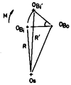
제11도에 의하여 상기 중심위치의 변화를 설명한다. 즉 편심부시의 외주면(301b)의 중심(Obo)를 중심으로하여 편심부시(301)는 화살표 M방향으로 회전하고 편심부시의 내주면(301a)의 중심(OBi)은 와권측판(101)(201)이 서로 접하는 점(OBi')까지 이동한다.11 illustrates the change of the center position. That is, the eccentric bush 301 rotates in the direction of arrow M with the center Obo of the outer circumferential surface 301b of the eccentric bush, and the center OBi of the inner circumferential surface 301a of the eccentric bush is the vortex winding side plate 101 (201). It moves to the point (OBi ') which is in contact with each other.

즉 요동스크롤(2)의 공전반경은

Figure kpo00003
에서
Figure kpo00004
까지 변화한다.In other words, the rotation radius of the rocking scroll (2)
Figure kpo00003
in
Figure kpo00004
To change.

또 반대로 공작의 정밀도에 의하여 공전반경이 R보다 작은 경우는 화살표 M과 반대방향으로 편심부시는 회전한다. 이것은 액배크(液 back)나 두와권측판(101)(201)사이로의 이동맞물림등의 경우에도 일어난다.On the contrary, when the revolution radius is smaller than R due to the precision of the work, the eccentric bushing rotates in the direction opposite to the arrow M. This also occurs in the case of a liquid back, moving engagement between the head and the side plates 101, 201, and the like.

이와같이 편심부시(5)는 공작의 정밀도의 불균형을 흡수하고 조립성을 쉽게하고, 더우기 압축시에 두와권측판(101)(201)사이를 통하여 와권방향으로 압축냉매가스가 새나가는 것을 방지하여 압축효율을 향상시키고, 또 액배크나 이물이 끼는데 대하여도 내력(耐力)이 있으며 신뢰성의 향상에도 유용한 것이다.In this way, the eccentric bush 5 absorbs an imbalance in the precision of the work and facilitates assembly, and furthermore, prevents the compressed refrigerant gas from leaking in the vortex winding direction between the head and winding plates 101 and 201 during compression. It improves the compression efficiency and has a bearing capacity against liquid bag and foreign matter, and is also useful for improving reliability.

다음에 본 발명의 상세하고 구체적인 설명을 하겠다.Next, a detailed and detailed description of the present invention will be given.

제12도는 상기 엘레멘트(6)을 요동스크롤 (2)의 와권측판(201)의 단면(201a)에 개구하고 와권길이방향을 따라 형성된 홈(5)에 압입하는 상태를 나타낸 조립시의 사시도다. 홈(5)은 와권측판(201)의 단면(201a)에 개구하고, 더우기 와권방향의 내단부(201b)및 외단부(201c)를 남기고 와권길이 방향을 따라서 형성되고 이홈(5)을 파묻듯이 끈 모양의 엘레멘트(6)를 홈(5)의 개구면에 수직으로 압입한다. 여기에서는 요동스크롤(2)의 예를 보였는데 고정스크롤(1)에 관하여도 마찬가지로 실시됨은 말할나위도 없다.FIG. 12 is a perspective view at the time of assembly showing the state in which the element 6 is opened in the end surface 201a of the vortex winding side plate 201 of the rocking scroll 2 and pressed into the groove 5 formed along the vortex winding direction. The groove 5 is opened in the end surface 201a of the spiral winding side plate 201, and is further formed along the spiral winding direction, leaving the inner end 201b and the outer edge 201c in the spiral winding direction, and buried the groove 5 as shown in FIG. The string-like element 6 is press-fitted perpendicularly to the opening face of the groove 5. Here, an example of the rocking scroll 2 is shown, but it goes without saying that the fixed scroll 1 is similarly implemented.

아래에 요동스크롤 (2)에 한하여 설명한다.Only the rocking scroll 2 will be described below.

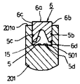
제13도는 이같은 상태에 있어서의 국부단면도이며, 상기 홈(5)및 엘레멘트(6)는 여기서는 단면구형의 형상을 택하고 있다.FIG. 13 is a local cross-sectional view in such a state, wherein the grooves 5 and the elements 6 take the shape of a cross section here.

여기에서 엘레멘트(6)의 폭길이 D는 홈의 폭길이 D'와 실질적으로 동등이상의 치수를 지니며, 또 엘레멘트(6)의 두께치수 H는 홈(5)의 깊이치수 H와 실질적으로 동등이거나 그것보다도 작은값이 되어 있다.Wherein the width D of the element 6 has a dimension substantially equal to or greater than the width D 'of the groove, and the thickness dimension H of the element 6 is substantially equal to the depth dimension H of the groove 5 It is smaller than that.

D>D'인 경우는 엘레멘트(6)는 폭방향으로 탄성변형 내지 소성변형하기쉬운 재질이 아니면 않되며, 따라서 엘레멘트(6)로서는 그같은 성질의 것이 사용된다. 어느 정도의 탄소성(彈塑性)과 가요성이 있고 또 자기윤활성이 있는 4불화 에틸렌수지등은 가장 적합하다. 제14도는 이와같은 엘레멘트(6)을 홈(5)안에 삽입한 상태를 보이는 국부단면도이며 엘레멘트(6)는 탄성변형(소성변형을 하여도 된다)하여 양축면(6b)(6c)가 홈(5)의 양측면(5b)(5c)와 밀착한 상태로 와권측판의 단면(201a)에서 돌출한 상태, 따라서 엘레멘트(6)의 하면(6d)과, 홈(5)의 저면(5d)사이에 공극(502)가 어느상태에서 정지되어 있다.In the case of D> D ', the element 6 must be a material which is easy to elastically or plastically deform in the width direction, and therefore, the element 6 has the same property. Ethylene tetrafluoride resin having some degree of carbonaceousness, flexibility, and self-lubrication property is most suitable. FIG. 14 is a local cross-sectional view showing the state in which such an element 6 is inserted into the groove 5, and the element 6 is elastically deformed (may be plastically deformed) so that both axis faces 6b and 6c are grooved. The state protruded from the end surface 201a of the spiral winding side plate in close contact with both side surfaces 5b and 5c of 5), and thus, between the bottom surface 6d of the element 6 and the bottom surface 5d of the groove 5. The void 502 is stopped at a certain state.

이 공극(502)의 축방향 치수를 δ로 한다.The axial dimension of this space | gap 502 is set to (delta).

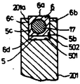
제15도는 이와같은 요동스크롤(2)에, 제6도에서 설명한것 같은 조립법으로 고정스크롤을 덮어서 고정한 상태를 나타낸 국부단면도이다.FIG. 15 is a local cross-sectional view showing a state where the rocking scroll 2 is covered with a fixed scroll by an assembling method as described in FIG.

고정스크롤(1)의 대판저면(102a)에 의하여 상기한 와권측판의 단면(201a)에서 돌출한 엘레멘트(6)는 홈(5)내로 화살표처럼 하향으로 털어 넣어지며 상기대판의 저면(102a)과 와권측판의 단면(201a)사이에 제6도에서 상술한 설정된 미소간극(a)이 생기는 위치까지 틀어넣어진 곳에서 머문다. 이때 상기 공극(501)의 축방향치수 δ'는 δ'<δ 가 되는 것은 물론이다.The element 6 protruding from the end face 201a of the vortex winding side plate by the base plate bottom 102a of the fixed scroll 1 is swept downward into the groove 5 as an arrow, and the bottom surface 102a of the base plate Between the end surface 201a of the spiral winding side plate, it stays in the position which entered to the position where the set micro clearance a mentioned above in FIG. 6 arises. At this time, the axial dimension δ 'of the gap 501 is of course δ' <δ.

여기에서 상기치수 δ'는 압축기가 운전중 특히 와권중심축이 고온이 되므로 중심측판이 축방향으로 열팽창에 의하여 국부적으로 뻗으며, 미소간극(A)의 치수가 국부적으로 축소되었다 하더라도 상대측 대판의 저면에 의하여 엘레멘트(6)가 국부적으로 축소되었다 하더라도 상대측 대판의 저면에 의하여 엘레멘트(6)가 더욱 홈(5)안의 하방 축방향으로 밀려서 이동하고, 이 열팽창에 의한 치수변화를 흡수 가능하도록 도피부로서 설정되어 있다.In this case, the dimension δ 'is a high temperature of the vortex center axis during the operation of the compressor, so that the central side plate is locally extended by thermal expansion in the axial direction, and even if the dimension of the micro gap A is locally reduced, Even if the element 6 is reduced locally, the element 6 is further pushed downward in the groove 5 in the groove 5 by the bottom surface of the mating plate and moved as a skin portion to absorb the dimensional change due to thermal expansion. It is set.

만일 엘레멘트(6)에 축방향으로 탄성력이 작용하고, 따라서 제15도의 상태에 있어서 엘레멘트(6)의 상면(6a)이 대판저면(102a)에 대하여 탄력성에 의한 밀어끼움이 과대하게 작용할 경우는 제16도에 보이듯이 대판(102)을 화살표방향으로 되돌려 엘레멘트(6)의 상면(6a)과 대판의 저면(102a)사이에 소정의 미소간극(A')이 트이도록 오프셋트 하면된다.If the elastic force acts on the element 6 in the axial direction, and therefore, in the state of FIG. 15, the upper surface 6a of the element 6 exerts an excessive force on the base plate surface 102a. As shown in FIG. 16, the base plate 102 may be returned in the direction of the arrow so as to offset a predetermined minute gap A 'between the upper surface 6a of the element 6 and the bottom surface 102a of the base plate.

상기 미소간극(A')는 래디얼 방향으로의 유체의 누설을 적게하는 관점에서 바람직하게는 10μ이하, 가장 바람직하게는 4-5μ 다.The microgap A 'is preferably 10 µm or less, most preferably 4-5 µm from the viewpoint of reducing leakage of fluid in the radial direction.

상기 오프셋트의 한방법을 제17도에 보인다.One method of such an offset is shown in FIG.

즉 제6도에서 설명한 조립방법에 의하여 조립한후 볼트(42)를 빼어 고정스크롤(1)을 상부프레임(40)에서 떼어 고정스크롤(1)의 주벽부의 저면(103a)의 상부프레임(40)의 설치면(40a)사이에 두께가 균일하며 그 치수가 (A')인 환상끼움쇠를 끼운 상태로 다시 볼트(42)를 조이므로 끼움쇠의 두께가 A'만큼 고정스크롤(1), 요동스크롤(2)의 각엘레멘트(6)의 상면(6a)과 이에 대응하는 대판의 저면(202a)(102a)사이에 미소간극(A')이 균일하게 형성된다.That is, after assembling according to the assembling method described in FIG. 6, the bolt 42 is removed and the fixed scroll 1 is removed from the upper frame 40, and the upper frame 40 of the bottom surface 103a of the main wall of the fixed scroll 1 is removed. Tighten the bolts 42 again with the annular shims with a uniform (A ') dimension between the mounting surfaces 40a of the A minute gap A 'is uniformly formed between the upper surface 6a of each element 6 of the scroll 2 and the bottom surface 202a, 102a of the base plate corresponding thereto.

제18도에 있어서, 이같은 오프셋트조립방법의 다른예에 관하여 설명한다.In FIG. 18, another example of such an offset assembling method will be described.

고정스크롤(1) 및 요동스크롤(2)의 와권측판(101)(201)의 단면(101a)(201a)의 홈(5)에는 미리 엘레멘트(6)를 소정의 미소간극(A)이상으로 돌출시켜 놓는다.The element 6 protrudes more than a predetermined minute gap A in advance in the groove 5 of the end faces 101a and 201a of the vortex winding side plates 101 and 201 of the fixed scroll 1 and the swinging scroll 2. Let it be.

이같은 상태로 상부프레임(40)을 그하면(40b)이 맞도록 견고한 평면(12a)의 대(臺)(12)위에 얹어넣고 상부프레임(40)상면에 고정된 상부스러스트베어링(402)의 베어링면(402a)위에 두께가 균일하며 그치수가 (A')의 상기 상부스러스트베어링(402)과 거의 동경(同徑)의 내외경인 환상의 끼움쇠(10)를 끼운다. 그리고 그위에 요동스크롤(2)을 그대판의 배면(202b)과, 상기 스러스트베어링(402)에서 상기 끼움쇠(10)를 끼워 넣도록 한다.In such a state, the upper frame 40 is placed on the base 12 of the solid plane 12a so that the bottom frame 40b fits and the bearing of the upper thrust bearing 402 fixed to the upper surface of the upper frame 40. An annular shim 10 is fitted on the surface 402a, the thickness of which is uniform, and the dimension of the upper thrust bearing 402 whose diameter is (A '). Then, the rocking scroll (2) on the back plate 202b and the thrust bearing (402) to fit the shim (10).

이같이 하여 상기 요동스크롤(2)의 와권측판(201)과 고정스크롤(1)의 와권형측판(101)이 서로 맞물리도록 하여 고정스크롤(1)을 덮는다.In this way, the vortex winding side plate 201 of the rocking scroll 2 and the vortex winding side plate 101 of the fixed scroll 1 are engaged with each other to cover the fixed scroll 1.

다음에 이같은 상태에서 상기 고정스크롤(1)의 상면(102b) 평판(12)을 개재시켜 프레스암(13)에 의하여 대(12)의 평면(12a)에 대하여 수직으로 눌러끼운다.Next, in such a state, the press arm 13 is pressed vertically with respect to the plane 12a of the base 12 via the flat plate 12 of the upper surface 102b of the fixed scroll 1.

그결과 고정스크롤(1), 요동스크롤(2)의 각 엘레멘트(6)는 각홈(5)안에 상대방의 대판의 저면(202a)(102a)로서 압입되고 소정의 간극(A)에서 끼움쇠 (10)의 두께(A')를 뺀치수 즉(A")만큼 균일하게 각홈(5)에서 돌출한 상태에서 멈춘다.As a result, each of the elements 6 of the fixed scroll 1 and the swinging scroll 2 is press-fitted into the groove 5 in the bottom surface 202a and 102a of the counterpart's base plate and fitted in the predetermined gap A. Stop at the state protruding from the angular groove (5) uniformly by the size (A ") minus the thickness (A ') of the).

그뒤 끼움쇠(10)를 꺼내고 다시 제6도에서 설명한 조립방법으로 조립을 하면 상기 각 엘레멘트(6)의 상면(6a)과 그것과 대응하는 상대방의 대판의 저면(102a)(202a)사이에는 균일하게 미소간극(A')이 형성된다.Then, the shim 10 is taken out and assembled again by the assembly method described in FIG. 6, and the uniformity between the upper surface 6a of each of the elements 6 and the bottom surfaces 102a and 202a of the counterpart of the counterpart corresponding thereto. A micro gap A 'is formed.

위와같은 조립에 있어서 각스크롤의 와권측판의 단면에 어드스팅(Adusting) 엘레멘트(6)와 이것을 삽입하는 홈(5)으로 이루어진 축방향의 간극 미조정기구를 설치함으로써 각 와권측판의 단면과 그것에 대응하는 대판의 저면과의 사이는 상기 엘레멘트(6)를 거쳐서 실질 간극을 없앤 상태 혹은 공작의 정밀도의 불균형을 배제한 필요 최소한의 미소간극에 쉽게 설치할수가 있고 압축시에 있어서의 와권반경방향의 냉매가스의 새나옴을 방지할수가 있다.In the above assembly, the cross section of each vortex winding plate and its corresponding portion are provided by providing an axial gap fine adjustment mechanism composed of an dusting element 6 and a groove 5 for inserting the vortex winding plate of each scroll. The gap between the bottom surface of the base plate can be easily installed in the state where the actual gap has been eliminated via the element 6 or in the minimum microgap necessary to eliminate the imbalance in the precision of the work. Can prevent leaks.

다시 엘레멘트(6)와 홈(5)이 당접하는 측면(6b)(6c) 및 (5d)(5c)는 실질 간극이 없으므로 이부분을 지나서 와권하류측으로의 새나옴도 생기지 않는다. 또 엘레멘트(6)는 홈(5) 안에 압입등으로 고정되어 있으므로, 본질적으로 대판의 저면에 대한 엘레멘트(6)의 상면(6a)의 압착은 생기지 않고, 따라서 정상으로 운전되는 경우 엘레멘트(6)의 상면(6a)의 마모는 생기지 않는다. 다시 상기 압착력이 대판의 저면에 발생하지 않는다는 것은 여기에서의 마찰저항은 없으며, 따라서 상기 편심부시(301)의 작동을 순조롭게 할수가 있다.Again, the side surfaces 6b, 6c and 5d, 5c, in which the elements 6 and the grooves 5 abut, do not have a real gap, so there is no bleeding downstream beyond this portion. In addition, since the element 6 is fixed in the groove 5 by press-fitting or the like, essentially no compression of the upper surface 6a of the element 6 to the bottom of the base plate occurs, and thus the element 6 when operated normally. The upper surface 6a of the wear does not occur. Again, the fact that the compressive force does not occur on the bottom of the base plate has no frictional resistance here, and thus the operation of the eccentric bush 301 can be smoothed.

즉 편심부시(301)의 요동운동에 의하여 이것에 감입한 요동스크롤(2)은 그축심이 주축(3)의 축심에 대하여 이동한다. 그리고 이 요동운동은 요동스크롤(2) 자체의 원심력등에 의하여 생긴다.That is, the rocking scroll 2 inserted into the rocking scroll 2 by the rocking motion of the eccentric bush 301 moves with respect to the axis of the main shaft 3. This rocking motion is caused by the centrifugal force of the rocking scroll 2 itself.

그런데 고정스크롤(1) 및 요동스크롤(2)의 와권측판의 단면(101a)(201a)에 과대한 힘이 작용하면 이 부분의 마찰저항과 더불어, 요동스크롤(2)의 스러스트방향의 힘이 지지하는 상부스러스트베어링(402)에도 과대한 힘이 부하되며, 결과로서 이들 접동부의 마찰저항은 상술한 원심력등에 의한 편심부시(301)의 요(搖)회동을 따라서 요동스크롤(2)의 와권측판(201)의 측면이 고정스크롤(1)의 와권측판(101)의 측면에 밀리는 방향으로 요동스크롤(2)이 이동하려는 것을 막도록 작용하고 상기 측판사이의 적절한 접촉이 않되어 이부분의 새나옴이 증대하고 성능의 열화를 초래하고 또 부하가 증대하면 상기 상부스러스트 베어링(402)등이 눌어붙지 않는다.However, when excessive force acts on the end surfaces 101a and 201a of the vortex winding side plate of the fixed scroll 1 and the swinging scroll 2, the frictional resistance of this portion and the force in the thrust direction of the swinging scroll 2 are supported. Excessive force is also applied to the upper thrust bearing 402, and as a result, the frictional resistance of these sliding portions is the vortex winding side plate of the swinging scroll 2 along the yaw rotation of the eccentric bush 301 due to the centrifugal force or the like described above. The side of the 201 acts to prevent the swinging scroll 2 from moving in the direction pushed against the side of the vortex winding plate 101 of the fixed scroll 1, and there is no proper contact between the side plates so that the leaking out of this part This increase, deterioration in performance, and increase in load prevent the upper thrust bearing 402 or the like from sticking.

본 발명에서는 상기 한대로 엘레멘트(6) 상면(6a)의 대판 각부의 저면(102a)(202a)으로의 압착이 본질적으로 발생하지 않으므로 상부스러스트베어링(402)으로의 부담은 걸리지 않으며 따라서 편심부시(301)의 작동을 부드럽게 할수가 있고 이에따라서 와권측판(101)(201)측면사이의 시일을 효과적으로 할수가 있다.In the present invention, since the compression of the upper surface 6a of the element 6 to the bottom surfaces 102a and 202a of the upper plate portion 6a is not inherently caused, the burden on the upper thrust bearing 402 is not applied and thus the eccentric bush 301 is used. ) Operation can be smoothed and thus the seal between the vortex winding side plate (101, 201) side can be effectively.

또 압접시에 와권중심측의 국부적인 열팽창의 차이에 의한 간극(A)의 감소로 말미암아 대판의 저면에 의한 엘레멘트(6)로의 국부적인 압착이 발생하여도 엘레멘트(6)의 홈(5)으로의 국부적인 이동에 의하여 흡수가 되고 이로인한 눌어붙는 사고도 막을 수가 있다. 다음에 제19도-제32도에 있어서, 본 발명의 다른 실시예를 설명한다.In addition, even when a local compression is caused to the element 6 by the bottom of the base plate due to the reduction of the gap A due to the difference in local thermal expansion on the vortex center side at the time of welding, the groove 5 of the element 6 This can be absorbed by local movement and prevents crushing accidents. Next, in FIGS. 19-32, another embodiment of the present invention will be described.

본 실시예에서는 요동스크롤(2)에 관한예를 보이는데 고정스크롤에도 마찬가지로 실시한다. 제19도는 엘레멘트(6)를 홈(5)에 장착할때 삽입을 쉽게하기 위하여 엘레멘트(6)의 양측면(6b)(6c)의 하단부 및 홈(5)의 양측면(5b)(5c)의 상단부의 와권길이 방향을 따라서 테이퍼부(14)를 마련한 것이다. 제20도는 마찬가지로 엘레멘트(6)의 단면에 있어서 양측면(6b)(6c)를 밖으로 배가 부르도록 북처럼 불쑥 나오게 함으로써 홈(5)으로의 삽입을 쉽게 하고 있다.In this embodiment, an example of the swinging scroll 2 is shown, but the same applies to the fixed scroll. 19 shows the lower end of both sides 6b and 6c of the element 6 and the upper end of both sides 5b and 5c of the groove 5 to facilitate insertion when mounting the element 6 to the groove 5. The tapered portion 14 is provided along the vortex length direction. Similarly, in FIG. 20, both sides 6b and 6c in the cross section of the element 6 are made to pop out like a drum so that the stomach is blown out, making insertion into the groove 5 easy.

제21도는 엘레멘트(6)의 하면(6d)에 와권길이 방향을 따라 요부(15)를 마련하여 홈(5)으로의 삽입을 쉽게함과 아울러 엘레멘트(6)가 지닌 탄성력을 보다더 효과적으로 그 측면부(6b)(6c)의 홈(5)에 대응하는 측면(5b)(5c)에 대하여 압착시킴과 아울러 삽입을 쉽게하고 있다.FIG. 21 provides a recessed portion 15 along the vortex length direction on the lower surface 6d of the element 6 to facilitate insertion into the groove 5, and to more effectively control the elastic force of the element 6. The side surfaces 5b and 5c corresponding to the grooves 5 of (6b) and 6c are pressed, and insertion is facilitated.

제22도는 마찬가지로 엘레멘트(6)에 와권길이 방향을 따라서 중공부를 마련한 것이다. 제23도-제27도는 엘레멘트(6)에 탄성체(17)를 개재시켜 탄성체(17)의 탄성력으로 엘레멘트(6)의 측면부(6b)(6c)의 홈(5)의 측면부(5b)(5c)에 대하여 압착성을 더욱 효과적으로 한것이다.Fig. 22 is similarly provided with a hollow portion in the element 6 along the vortex length direction. 23 to 27 illustrate the side portions 5b and 5c of the grooves 5 of the side portions 6b and 6c of the element 6 by the elastic force of the elastic body 17 with the elastic body 17 interposed between the elements 6. It is more effective to compress against).

즉 제23도는 엘레멘트(6)하면 (6d)에 와권길이 방향을 따라서 요부(15)를 마련하여 이 요부(15)안에 와권길이 방향을 따라서 단면원형의 탄성체(17)을 개재시킨 것이다. 제24도는 엘레멘트(6)의 한측면(6c)과 이에 대응하는 홈(5c)사이에 와권길이 방향을 따라서 탄성체(17)를 개재시킨 것이다. 제25도는 엘레멘트(6) 내부에 탄성체(17)를 와권길이 방향을 따라서 포함시킨 것이며, 도면에서는 탄성체(17)는 단면원형이 되어 있다.That is, in FIG. 23, the recessed part 15 is provided in 6 d of elements 6 in the vortex length direction, and the elastic body 17 of circular cross section is provided in this recessed part 15 along the vortex length direction. FIG. 24 shows the elastic body 17 interposed between the one side 6c of the element 6 and the groove 5c corresponding thereto along the vortex length direction. 25, the elastic body 17 is included in the element 6 along the vortex length direction. In the drawing, the elastic body 17 has a circular cross section.

또 제26도는 엘레멘트(6)의 하면(6d)에 와권길이 방향을 따라 요부(15)를 마련하고 이 요부(15)에 밀착시켜서 단면 <형의 금속성의 스프링(18)을 개재시킨 것이다. 제27도는 엘레멘트(6)의 하면(6d)에 와권의 길이 방향에 따른 탄성체(17)를 개재시킨 것이며 도면에서는 엘레멘트(6)와 탄성체(17)의 축방향의 두께는 거의같은 치수가 되어있으며, 홈(5)의 측면(5b)(5c)에 엘레멘트(6), 탄성체(17)의 각 측면(6b)(6c)(17b)(17c)이 접하도록 되어있는데, 이것은 엘레멘트(6)의 홈(5)으로부터의 탈락을 막기위한 것이며, 엘레멘트(6)와 탄성체(17)의 밀착이 잘된것이면 탄성체(17)의 상면(17a)에 엘레멘트(6)를 얇게, 가령 코오팅한것 같은 것이라도 된다.In FIG. 26, the recessed part 15 is provided in the lower surface 6d of the element 6 along the vortex length direction, and it adhere | attached on this recessed part 15, and interposed the metallic spring 18 of the cross-<< shape. FIG. 27 shows the elastic body 17 along the longitudinal direction of the vortex on the lower surface 6d of the element 6. In the drawing, the thicknesses in the axial direction of the element 6 and the elastic body 17 have almost the same dimensions. The elements 6 and the side surfaces 6b, 6c, 17b and 17c of the elastic body 17 are in contact with the side surfaces 5b and 5c of the groove 5, It is to prevent the fall from the groove 5, and if the element 6 and the elastic body 17 are in close contact with each other, the element 6 is thinly coated on the upper surface 17a of the elastic body 17, for example, coated. You may also

제28도에서는 홈(5)의 양측면(5b)(5c)를 테이퍼형으로 만든것이며, 이같은 홈(5)에 엘레멘트(6)를 삽입하면 엘레멘트(6)는 하방으로 눌릴수록 압착력을 더해가지 않으면 아니되므로 형상과 치수를 적절한 것으로 설정함으로서 필요이상으로 함몰하는 일은 없다. 도면에서는 엘레멘트(6)는 그하면(6b)에 요부(16)를 형성하고 있는데, 이것은 삽입을 쉽게 하는 것이며 양측면을 테이퍼형으로 하여도 된다.In FIG. 28, both side surfaces 5b and 5c of the groove 5 are tapered. When the element 6 is inserted into the groove 5, the element 6 is pressed downward so as not to increase the pressing force. Therefore, by setting the shape and dimensions as appropriate, it is not necessary to dent more than necessary. In the drawing, the element 6 forms a recessed portion 16 on its lower surface 6b, which is easy to insert and may be tapered on both sides.

제29도는 와권측판(201)의 단면(201a)에 가이드부로서 홈이 아니라 돌기(19)를 와권길이 방향으로 형성한 경우의 예를 보인다.FIG. 29 shows an example in which the projections 19, not grooves, are formed in the vortex length direction in the end face 201a of the vortex winding side plate 201 as guides.

이경우는 엘레멘트(6)의 하면(6d)에 상기돌기(19)에 대응한 형상의 홈(16)이 길이방향으로 설치되고 상기돌기(19)에 홈(16)의 내측면(16b)(16c)과 돌기양측면(19b)(19c)으로 압입되어 있다.In this case, a groove 16 having a shape corresponding to the projection 19 is provided in the longitudinal direction on the lower surface 6d of the element 6, and the inner surfaces 16b and 16c of the groove 16 are provided in the projection 19. ) And projections on both sides 19b and 19c.

이경우에도 압입후의 다소의 축방향의 자유도(度)를 갖게 하기위하여 엘레멘트(6)의 하면(6d)과 와권측판의 단면(201a), 홈(16)안의 상면(16a)과 돌기상단부(19a)의 사이에 각각 간극(502)(502')이 있다.Also in this case, in order to have some axial degrees of freedom after the press-fitting, the lower surface 6d of the element 6 and the end face 201a of the vortex winding side plate, the upper surface 16a in the groove 16 and the upper projection 19a Are gaps 502 and 502 ', respectively.

제30도, 제31도는 엘레멘트(6)의 필요이상의 함락을 막기위한 홈(5)의 저면(5d)과 엘레멘트(6)의 하면(6d)사이에 소성변형이 되기쉬운 재질(20)을 개재시킨 것이며, 즉 제30도에 보인것같은 방판상의 가소성재료(20)를 V자형으로 굽힌모양의 것(가령 납같은 것도 된다)을 제31도에 보이듯이 홈(5)의 저면(5d)과 엘레멘트(6)의 하면(6d)사이에 와권길이 방향을 따라서 개재시킨다.30 and 31 show a material 20 that is susceptible to plastic deformation between the bottom face 5d of the groove 5 and the bottom face 6d of the element 6 to prevent the element 6 from falling more than necessary. In other words, as shown in FIG. 31, the shape of the curved plastic material 20 as shown in FIG. 30 is bent in a V shape (for example, lead-like material) and the bottom surface 5d of the groove 5 is formed. It interposes along the vortex length direction between the lower surfaces 6d of the elements 6.

이같이 하여 제32도의 화살표처럼 엘레멘트(6)의 상면(6a)으로부터 눌리면 가소성 재료는 소성변형을 하여 적당한 형상으로 엘레멘트(6)를 하면서 지탱한다.Thus, when pressed from the upper surface 6a of the element 6, as shown by the arrow of FIG. 32, the plastic material carries out plastic deformation and supports the element 6 in a suitable shape.

이같이하여 엘레멘트(6)의 측면(6b)(6c)의 탄력성에 의한 지지이외에도 홈의 저면(5d)에서도 지지되므로 엘레멘트(6)는 더욱 안정되게 홈(5)안에 고정된다. 또 상기 실시예에 있어서는 간극조정용 엘레멘트(6)을 감합부(5)나 (19)에 압입함으로서 이 압입으로 생기는 극간 조정용 엘레멘트(6)와 감합부(5)나 (19)와의 사이의 밀착력에 의하여 극간 조정용 엘레멘트(6)를 감합부(5)혹은 (19)에 고착한 경우에 관하여 설명하였는데, 상기 극간 조정용 엘레멘트와 감합부(5)혹은 (19)와의 고착은, 상기 밀착력 만에 의한 고착수단에 한하지않고, 다른 고착수단에 의하여도 상기 실시예와 동등의 효과를 나타낸다.Thus, the element 6 is more securely fixed in the groove 5 because it is supported not only by the elasticity of the side surfaces 6b, 6c of the element 6, but also on the bottom surface 5d of the groove. In the above embodiment, the gap adjustment element 6 is press-fitted into the fitting part 5 or 19 so that the adhesion force between the gap adjusting element 6 and the fitting part 5 or 19 caused by the press-fitting is adjusted. The case where the inter-pole adjustment element 6 is fixed to the fitting portion 5 or 19 is described. However, the adhesion between the inter-pole adjustment element and the fitting portion 5 or 19 is fixed only by the adhesion force. Not only the means but also other fixing means exhibits the same effect as the above embodiment.

다른 고착수단의 하나는, 가령 용착에 의한 것으로서 가령 상기 실시예에 있어서의 미소간극(A)이 두 스푸울(spool)(1)(2)을 최종적으로 조합해버린때 소정의 미소간극이 되도록 사전에 상기 극간조정용 엘레멘트(6)를 감입부(5), 혹은 (19)에 소정량 압입을 한 상태에 있어서, 상기 극간조정용 엘레멘트(6)및 감입부(5) 혹은 (19)의 적어도 한쪽을 가령 레이저비임(lazor beam)을 이용한 가열수단등에 의하여 가열하여 용융한뒤 다시 굳치면 상기 용착이 된다.One of the other fixing means is, for example, by welding, so that, for example, the microgap A in the above embodiment becomes a predetermined microgap when the two spools 1 and 2 are finally combined. At least one of the clearance adjustment element 6 and the penetration section 5 or 19 in the state where the clearance adjustment element 6 has been press-fitted in the insertion section 5 or 19 in a predetermined amount in advance. For example, the welding is performed by heating and melting by heating means using a laser beam, and then hardening again.

또 이경우 상기용착을 확실히 하기위하여 상기 극간조정용 엘레멘트(6) 및 감합부(5) 혹은 (19)의 용착된 각면을 미리거치른면에 가공하든지 혹은 그 각면에 적극적으로 요철을 형성하여 놓는것이 바람직하다. 또 상기용착은 다만 물리적으로 밀착 접촉한 용착혹은 용접등에 의한 소위분자 결합에 의한 용착의 쌍방울 뜻한다.In this case, in order to ensure the welding, it is preferable to process the welded facets of the clearance adjusting element 6 and the fitting part 5 or 19 on the roughened surface in advance or to form the unevenness actively on each facet. . In addition, the above-mentioned welding means only two drops of welding by so-called molecular bonding by welding or physical contact with each other.

또 상기 이외의 고착수단의 하나는 가령 접착제를 이용한 고착수단이며 지건성의 접착제를 사용할 경우는, 예컨데 조립공정의 최초에 극간 조정용 엘레멘트(6)및 감합부(5) 혹은 (19)중 적어도 한쪽의 접착해야할 부분에 미리 부착해 놓아도 되지만 지건성 혹은 비교적 속건성의 어느 접착제라도 양스크롤(1)(2)가 최종적으로 조합되기전, 즉 한쪽스크롤(2)이 다른쪽 스크롤(1)에 의하여 덮여지기전의 공정의 적당한 단계에서 붙치면 된다.One of the fixing means other than the above is, for example, a fixing means using an adhesive, and in the case of using a slow-drying adhesive, for example, at least one of the gap adjusting element 6 and the fitting portion 5 or 19 at the beginning of the assembling process. It may be attached to the portion to be bonded in advance, but any of the slow-drying or relatively fast-drying adhesives may be covered before both scrolls 1 and 2 are finally combined, that is, one scroll 2 is covered by the other scroll 1. This can be done at the appropriate stages of the process before loading.

또 이접착제에 의한 고착을 할 경우도 상기 극간조정용 엘레멘트(6)및 감합부(5) 혹은 (19)가 접착되는 각면을 미리 거칠게 가공을 하든지 혹은 각면에 적극적으로 요철을 형성해 놓는것이 상기 접착을 확실히 하기 위하여 바람직하다.In addition, in the case of fixing with an easy adhesive, each surface to which the clearance adjusting element 6 and the fitting portion 5 or 19 are bonded is roughly processed in advance, or an unevenness is actively formed on each surface. It is desirable to ensure.

또 예컨데 제20도-제29도, 제31도, 제32도에 보인 상태에 있어서 상기 접착제로 붙칠 경우에는 극간조정용 엘레멘트(6)과 감합부(5) 혹은 (19)사이의 공간에 접착제를 소정압력으로 주입할 필요가 있다.For example, in the state shown in FIGS. 20 to 29, 31 and 32, the adhesive is applied to the space between the clearance adjusting element 6 and the fitting portion 5 or 19 when the adhesive is applied. It is necessary to inject at a predetermined pressure.

이상 설명하듯이 본 발명에 의하면 스크롤 유체기계에 있어서 스크롤의 와권형 측판의 단면에 설치한 감합부에, 균등하게 미조정용 엘레멘트를 압입등에 의하여 감합 또는 실질적으로 고정함으로써 상기 미조정용 엘레멘트를 거쳐서 고정스크롤 및 요동스크롤의 각와권형 측판의 단면과 대판의 저면의 사이의 축방향간극의 미조정을 할수가 있으며, 고정스크롤, 요동스크롤등의 공작의 정밀도가 불균형을 배제하고 실질간극이 없는, 혹은 필요최소한의 미소간극으로 조정이 가능하고 또 미조정 엘레멘트 대사판사이에는 가압력이 발생하지 않으므로 마찰저항이나 마모가 없고 또 엘레멘트와 홈의 사이는 실질간극이 없으므로 와권하류측으로의 새나옴도 없고, 구조가 간단하며 조립이 용이한 극간 미조정기구를 지닌 스크롤 유체기계를 제공하는 것이다.As described above, according to the present invention, in the scroll fluid machine, a fixed scroll is provided through the fine adjustment element by equally fitting or substantially fixing the fine adjustment element by press-fitting or the like to the fitting portion provided on the end face of the spiral winding side plate of the scroll. And fine adjustment of the axial gap between the angle of the swing scroll and the end face of the winding side plate and the bottom of the base plate, and the precision of the work such as the fixed scroll and the swing scroll eliminates the imbalance and there is no real gap or the required minimum. It is possible to adjust with a small gap of 하고 and there is no pressing force between the unadjusted element swash plate, so there is no frictional resistance or abrasion, and there is no real gap between the element and the groove. To provide scroll fluid machines with inter-fine adjustment mechanisms for ease of assembly The.

Claims (51)

각 와권측판이 대면판에 설치된 고정스크롤과 요동스크롤을 서로 조합시키고, 상기 요동스크롤을 요동운동시켜 유체를 이송, 압축 내지 팽창시키도록 구성한 스크롤 유체기계에 있어서, 와권축선 방향으로 연재하는 감합부를 상기 두 스크롤, 상기 와권측판의 와권축선 방향의 단면(端面)에 설치함과 동시에 각 상대측의 스크롤의 대판사이에 상기 와권축선 방향으로 소정의 미소간극(A')를 형성하도록 조정된 상태로 상기 각 감합부에 감합, 또는 실질적으로 고정되고 어느것이나 상기 와권축판에 따른 형상을 지닌 극간 조정용 엘레멘트를 설치하고, 상기 극간조정용 엘레멘트와 상기 감합부가 조정된 위치관계 및 상기 미소간극(A')을 적어도 상기 와권축선 방향에 대하여 유지하는 수단을 강구한 것을 특징으로 하는 스크롤 유체기계.A scroll fluid machine configured to combine a fixed scroll and a swinging scroll provided on a facing plate with each swirling side, and to oscillate the swinging scroll to convey, compress or expand a fluid, wherein the fitting portion extending in the vortex winding direction is provided. Each of the scrolls is installed in a cross section of the vortex winding direction of the vortex winding side plate and is adjusted to form a predetermined minute gap A 'in the vortex winding direction between the base plates of the scrolls on each side. An inter-pole adjustment element fitted to, or substantially fixed to, the fitting portion and having a shape corresponding to the vortex winding plate is provided, and the positional relationship between the inter-pole adjustment element and the fitting portion adjusted and the micro gap A 'are at least. And a means for retaining the spiral winding direction. 청구범위 제1항에 있어서, 고정프레임(40)을 갖추고 있으며, 이 프레임에 고정스크롤이 설치되고, 상기 고정스크롤과 상기 프레임 사이에 요동 스크롤이 개재해 있으며, 상기 극간 조정용 엘레멘트와 상기 감합부와의 조정된 위치관계를 적어도 와권축선방향에 대하여 유지하는 수단이 상기 서로 설치된 고정스크롤 및 프레임인것을 특징으로 하는 스크롤 유체기계.According to claim 1, having a fixed frame (40), a fixed scroll is installed on the frame, a rocking scroll is interposed between the fixed scroll and the frame, the inter-element adjusting element and the fitting portion and And a means for maintaining the adjusted positional relationship of at least with respect to the vortex direction is the fixed scroll and the frame provided with each other. 청구범위 제2항에 있어서, 상기 요동스크롤은 상기 고정스크롤과 반대측에 축(203)을 지니며, 이축(203)은 그 축심이 소정량 빗나간 주축(3)의 단부와 결합되어 상기 주축(3)에 의하여 그 주축(3)의 축심의 주위를 회전되게되고, 또 상기주축(3)과 상기 요동스크롤의 축(203)의 결합체가 상기프레임(40)을 관통하고 있음을 특징으로 하는 스크롤 유체기계.3. The rocking scroll according to claim 2, wherein the rocking scroll has a shaft 203 on the side opposite to the fixed scroll, and the biaxial shaft 203 is coupled to an end of the main shaft 3 whose axis is deflected by a predetermined amount. Scroll fluid around the shaft center of the main shaft (3), and a combination of the main shaft (3) and the shaft (203) of the rocking scroll penetrates the frame (40). machine. 청구범위 제3항에 있어서, 상기 요동스크롤의 축(203)과 상기 주축(3)과는 상기 요동스크롤의 축(203)을 둘러싼 환상의 부시(301)을 거쳐서 결합되어 있으며, 상기 주축(3)의 상기 단부는 상기프레임(40)에 베어링(403)을 개재하여 래디얼 방향으로 지지되고 있음을 특징으로 하는 스크롤 유체기계.The shaft (3) according to claim 3, wherein the shaft (203) and the spindle (3) of the rocking scroll are coupled via an annular bush (301) surrounding the shaft (203) of the rocking scroll, and the spindle (3). Scroll end machine, characterized in that the end of the frame is supported in the radial direction via a bearing (403) on the frame (40). 청구범위 제4항에 있어서, 상기 부시(301)는 상기 요동스크롤의 축(203) 및 주축(3)의 어느것에 대하여도 동방향으로 회동이 가능함을 특징으로 하는 스크롤 유체기계.5. A scroll fluid machine according to claim 4, wherein the bush (301) is capable of rotating in the same direction with respect to both the axis (203) and the main axis (3) of the oscillating scroll. 청구범위 제5항에 있어서, 상기 부시(301)는 그 내주면(301a)의 중심(OBi)과 그 외주면(301b)의 중심(OBo)이 래디얼 방향으로 소정거리 ε 만큼만 어긋나 있음을 특징으로 하는 스크롤 유체기계.6. The scroll according to claim 5, wherein the bush 301 is characterized in that the center OBi of the inner circumferential surface 301a and the center OBo of the outer circumferential surface 301b are shifted only by a predetermined distance ε in the radial direction. Fluid machinery. 청구범위 제4항에 있어서, 다시 상기 요동스크롤의 대판(202)의 상기 고정스크롤(1)과 반대측면과 상기프레임(40)의 상기 요동스크롤축의 면과 사이에 개재한 자전방지기구(401)를 갖추고 있으며 상기 자전방지기구(401)는 상기프레임(40) 및 상기 요동스크롤(2)의 쌍방과 상대적으로 래디얼 방향 만큼이동 가능하도록 결합하여, 상기 요동스크롤(2)의 상기프레임(40)에 대하여 동방향으로 회전, 즉 자전하는 것을 방지하는 것을 특징으로 하는 유체기계.5. The anti-rotation mechanism 401 according to claim 4, wherein the anti-rotation mechanism 401 is interposed between the fixed scroll 1 of the base plate 202 of the rocking scroll and the surface of the rocking scroll shaft of the frame 40. The anti-rotation mechanism 401 is coupled to both the frame 40 and the rocking scroll 2 to be movable in a radial direction relatively to the frame 40 of the rocking scroll 2. A fluid machine characterized by preventing rotation in the same direction, i.e., rotation. 청구범위 제4항에 있어서, 또 상기 요동스크롤(2)에 작용하는 스러스트 하중을 받는 스러스트베어링(402)을 갖추고 있으며, 상기 스러스트베어링(402)은 상기프레임(40)에 지탱되어 있음을 특징으로 하는 스크롤 유체기계.The method according to claim 4, further comprising a thrust bearing 402 subjected to a thrust load acting on the oscillating scroll 2, wherein the thrust bearing 402 is supported by the frame 40. Scroll fluid machine. 청구범위 제6항에 있어서, 또 상기 요동스크롤의 대판(202)의 상기 고정스크롤(1)과 반대측의 면과 상기프레임(40)의 상기 요동스크롤 측면 사이에 개재한 자전방지기구(401)과, 상기 요동스크롤(2)에 작용하는 스러스트 하중을 받는 스러스트베어링(402)과를 갖추고 있으며, 상기 자전방지기구(401)는 상기프레임(40)및 상기 요동스크롤(2)의 쌍방과 상대적으로 래디얼 방향만큼 이동이 가능하도록 결합하여 상기 요동스크롤(2)이 상기프레임(40)에 대하여 주방향으로 회전, 즉 자전하는 것을 방지하는 것이며, 상기 스러스트베어링(402)은 상기 자전방지기구(401)에서 래디얼 방향의 내측에 있으며, 더우기 상기프레임(40)에 설치되어 있는 것을 특징으로하는 스크롤 유체기계.The anti-rotation mechanism 401 according to claim 6, further comprising an interlock between the surface opposite to the fixed scroll 1 of the base 202 of the rocking scroll and the rocking scroll side of the frame 40. And a thrust bearing 402 subjected to a thrust load acting on the rocking scroll 2, and the anti-rotation mechanism 401 radially relatively to both the frame 40 and the rocking scroll 2; It is coupled so as to move in a direction to prevent the swinging scroll 2 from rotating, i.e., rotating in the circumferential direction with respect to the frame 40. Scroll fluid machine which is located in the radial direction, and further installed in the frame (40). 청구범위 제3항에 있어서, 상기 고정스크롤(1), 요동스크롤(2), 주축(3)및 프레임(40)이 쉘(9)내에 수납되고, 상기 고정스크롤(1)이 상기 요동스크롤(2) 및 상기프레임(40)보다 상측에 위치하며, 상기 요동스크롤(2)이 상기 주축(3)에서 상측에 위치하고, 상기프레임(40)은 반유공(40b)를 지니며, 상기 쉘(9)의 저부(9)에는 기름(907)이 고여있으며, 상기 주축(3)은 그 축심과 편심하여 그 축심에 따라 상하로 연재하는 편심 급유공(3b)을 지니고 있으며, 상기 주축(3)이 회전하면 상기 쉘(9)의 저부의 기름(907)이 상기 편심공(3b)을 지나서 상기 주축(3)과 상기 요동스크롤(2)의 축(203)의 결합부에 공급되고, 이 결합부에 공급된 기름의 대부분이 상기 반유공(40b)에서 상기 쉘(9)의 저부로 반유되고, 나머지 기름이 상기 양스크롤(1)(2)사이에 있어서 상기 유체를 이송, 압축, 내지 팽창시키는 실(P)로 공급되는 것을 특징으로 하는 스크롤 유체기계.The fixed scroll (1), the swinging scroll (2), the main shaft (3) and the frame (40) are housed in a shell (9), and the fixed scroll (1) is the swinging scroll ( 2) and above the frame 40, the rocking scroll (2) is located above the main shaft (3), the frame (40) has a semi-oil hole (40b), the shell (9) On the bottom 9 of), oil 907 is accumulated, and the main shaft 3 has an eccentric oil supply hole 3b which is eccentric with its axial center and extends up and down in accordance with the axial center. When rotated, oil 907 at the bottom of the shell 9 is supplied to the engaging portion of the main shaft 3 and the shaft 203 of the oscillating scroll 2 past the eccentric hole 3b. Most of the oil supplied to the oil is semi-oiled from the semi-oil hole 40b to the bottom of the shell 9, and the remaining oil transfers, compresses, or compresses the fluid between the scrolls 1 and 2. Scroll fluid machine characterized in that the supply to the chamber (P) of the window. 청구범위 제9항에 있어서, 상기 고정스크롤(1), 요동스크롤(2), 주축(3)및 프레임(40)이 쉘(9)내에 수납되고, 상기 고정스크롤(1)이 상기 요동스크롤(2) 및 상기프레임(40)보다 상측에 위치하며, 상기 요동스크롤(2)이 상기주축(3)보다 상측에 위치하며, 상기프레임(40)은 반유공(40b)를 지니며, 상기 쉘(9)의 저부에는 기름(907)이 저류되어 있으며, 상기 주축(3)은 그 축심과 편심하여 그 축심을 따라 상하로 연재하는 편심급유공(3b)를 지니고 있으며, 상기 주축(3)이 회전하면, 상기 쉘(9)의 저부의 기름(907)이 상기 편심급유공(3b)을 지나, 상기부시(301)에서 상기 스러스트베어링(402)으로, 다시 이 스러스트베어링(402)에서 상기 자전방지기구(401)로 공급되고, 이 자전방지기구(401)에 공급된 기름의 대부분이 상기 반유공(40b)에서 상기 쉘(9)의 저부로 반유되고 잔유가 상기 양스크롤(1)(2)사이에 있어서 상기유체를 이송, 압축 내지 팽창시키는 실(P)로 공급되는것을 특징으로 하는 스크롤 유체기계.The fixed scroll (1), the swinging scroll (2), the main shaft (3) and the frame (40) are housed in a shell (9), and the fixed scroll (1) is the swinging scroll ( 2) and the upper side than the frame 40, the rocking scroll (2) is located above the main shaft (3), the frame (40) has a semi-perforation (40b), the shell ( At the bottom of 9), oil 907 is stored, and the main shaft 3 has an eccentric oil supply hole 3b which is eccentric with its axis and extends up and down along the axis, and the main shaft 3 rotates. When the oil 907 at the bottom of the shell 9 passes through the eccentric oil hole 3b, from the bush 301 to the thrust bearing 402, the thrust bearing 402 prevents the rotation. Most of the oil supplied to the mechanism 401 is supplied to the anti-rotation mechanism 401 from the semi oil hole 40b to the bottom of the shell 9 and the remaining oil is Scroll (1) and (2) transport between the fluid in the scroll fluid machine characterized in that the supply to the chamber (P) of the compression to expansion. 청구범위 제1, 또는 제11항에 있어서, 극간조정용 엘레멘트(6)는 탄성형 and/or 소성변형하는 재료로 형성되어 있는 것을 특징으로 하는 스크롤 유체기계.Scroll fluid machine according to claim 1 or 11, characterized in that the clearance adjustment element (6) is formed of a material which is elastic and / or plastically deformed. 청구범위 제12항에 있어서, 극간조정용 엘레멘트(6)는 4불화에틸렌수지로 형성되고 있음을 특징으로 하는 스크롤 유체기계.13. A scroll fluid machine according to claim 12, characterized in that the clearance adjustment element (6) is formed of ethylene tetrafluoride resin. 청구범위 제1 혹은 제11항에 있어서, 감합부는 상기 고정스크롤(1)및 상기 요동스크롤(2)의 각 와권측판(101)(201)의 상기 와권축선방향의 단면에 형성된 홈(5)이며, 이 홈(5)에 상기 극간조정용 엘레멘트(6)가 감입되어 있는 것을 특징으로 하는 스크롤 유체기계.12. The groove (5) according to claim 1 or 11, wherein the fitting portion is a groove (5) formed in a cross section of the vortex winding direction of each vortex winding plate (101) 201 of the fixed scroll (1) and the swinging scroll (2). And the gap adjusting element (6) is inserted into the groove (5). 청구범위 제14항에 있어서, 상기 극간조정용 엘레멘트(6)의 래디얼 방향의 폭은 상기 홈(5)의 래디얼 방향의 폭보다 넓은 것을 특징으로 하는 스크롤 유체기계.Scroll scroll machine according to claim 14, characterized in that the width in the radial direction of the clearance adjustment element (6) is wider than the width in the radial direction of the groove (5). 청구범위 제14에 있어서, 상기 극간조정용 엘레멘트(6)와 상기홈(5)으로 공간(502)이 계획되어 있으며, 상기 양스크롤(1)(2)사이에 있어서 상기 유체를 이송, 압축 내지 팽창시키는 실(P)과 상기공간(502)과는 상기 압입에 의하여 시일되어있는것을 특징으로 하는 스크롤 유체기계.According to claim 14, a space 502 is planned as the clearance adjusting element 6 and the groove 5, and the fluid is conveyed, compressed or expanded between the scrolls 1 and 2, respectively. And the seal (P) and the space (502) are sealed by the press-fitting. 청구범위 제14항에 있어서, 상기 극간조정용 엘레멘트(6)가 면하는 스크롤 대판(102)(202)과 상기 극간조정용 엘레멘트(6)과의 사이에 미소간극(A')은 상기 스크롤대판(102)(202)과 상기 와권측판(101)(201)의 와권축선방향의 단면과의 사이의 거리(A)보다 작은 것을 특징으로 하는 스크롤 유체기계.The micro-gap (A ') between the scroll base (102) (202) facing the gap adjusting element (6) and the gap adjusting element (6) is the scroll base (102). And (202) the distance (A) between the vortex winding side plate (101) and the cross section of the vortex winding direction. 청구범위 제14항에 있어서, 상기 극간조정용 엘레멘트(6)은 상기 와권측판(101)(201)에 압입, 더우기 접착, 용착의 어느 수단에 의하여 견고하게 고정되어 있는 것을 특징으로 하는 스크롤 유체기계.The scroll fluid machine according to claim 14, wherein the clearance adjusting element (6) is firmly fixed to the vortex winding side plate (101) (201) by any means of press fitting, further adhesion and welding. 청구범위 제18항에 있어서, 상기 극간조정용 엘레멘트(6)는 그와권방향에서 본단면 형상이 장방형이며 그 측면(6b)(6c)가 상기 홈(4)의 측면(5b)(5c)에 직접 접촉하고 있음을 특징으로 하는 스크롤 유체기계.19. The clearance adjusting element (6) according to claim 18, wherein the clearance adjusting element (6) has a rectangular main cross-sectional shape in its winding direction and its side surfaces (6b) and (6c) are formed on the side surfaces (5b) and (5c) of the groove (4). Scroll fluid machine, characterized in that in direct contact. 청구범위 제18항에 있어서, 상기 홈(5)은 그 입구부에 테이퍼부(14)(14)가 형성되어 있으며, 상기 극간조정용 엘레멘트(6)의 상기 홈(5)측의 각부에 테이퍼(14), (14)가 형성되어 있음을 특징으로 하는 스크롤 유체기계.20. The groove 5 is provided with tapered portions 14, 14 at its inlet, and tapered at each side of the groove 5 side of the clearance adjustment element 6. 14), (14), characterized in that the scroll fluid machine. 청구범위 제18항에 있어서, 상기 극간조정용 엘레멘트(6)은 그 측면(6b)(6c)가 만곡되어 있음을 특징으로 하는 스크롤 유체기계.19. Scroll fluid machine according to claim 18, characterized in that the clearance adjustment element (6) is curved at its side (6b) (6c). 청구범위 제14항에 있어서, 상기 극간조정 엘레멘트(6)는 상기 홈(5)의 저면(5d)에 대향하는 면(6d)에 이 엘레멘트(6)의 요부(15)가 형성되어 있음을 특징으로 하는 스크롤 유체기계.15. The recessed portion (15) of claim 14 is characterized in that the clearance adjustment element (6) has a recess (15) of the element (6) formed on a surface (6d) opposite the bottom (5d) of the groove (5). Scroll fluid machines. 청구범위 제22항에 있어서, 상기 요부(15)는 그 와권방항에서 본 단면형상이 거의 U자 형상이며, 그요부(15)에 그요부(15)의 와권형상을 따라 연재하는 탄성체(17)가 감합되어 있음을 특징으로 하는 스크롤 유체기계.23. The elastic body (17) according to claim 22, wherein the recessed portion (15) has a substantially U-shaped cross-sectional shape viewed from the swirling winding direction and extends along the swirling shape of the recessed portion (15) to the recessed portion (15). Scroll fluid machine, characterized in that the fitting. 청구범위 제22항에 있어서, 상기 요부(15)는 그와권방향에서 본 단면형상이 거의 V자형상이며, 이 V자형의 요부(15)의 양측면에 상기 와권방향을 본 단면형상이 대략 V자형의 나사(18)가 그 양측면에 밀착하고 상기 V자형의 요부(15)의 와권형상을 따라 연재하고 있음을 특징으로 하는 스크롤 유체기계.23. The cross section of claim 22, wherein the recessed portion 15 is substantially V-shaped in cross section seen from the vortex winding direction. A scroll fluid machine, characterized in that the female screw (18) is in close contact with both sides thereof and extends along the spiral shape of the V-shaped recess (15). 청구범위 제14항에 있어서, 상기 극간조정 엘레멘트(6)는 그와권형상을 따라 연재하는 중공부(16)가 형성되어 있는 것을 특징으로 하는 스크롤 유체기계.15. A scroll fluid machine according to claim 14, characterized in that the clearance adjustment element (6) has a hollow portion (16) extending along its winding shape. 청구범위 제25항에 있어서, 상기 중공부(16)안에는 그 와권형상을 따라 연재하는 탄성체(17)가 장전되어 있는 것을 특징으로 하는 스크롤 유체기계.26. A scroll fluid machine according to claim 25, characterized in that the hollow part (16) is loaded with an elastic body (17) extending along its spiral winding shape. 청구범위 제14항에 있어서, 상기 홈(5)의 측면(5c)과, 이 측면(5c)에 대응하는 상기 극간조정 엘레멘트(6)의 측면(6c)사이에는 상기 홈(5)의 와권형상을 따라 연재한 탄성체(17)가 개재하고 있음을 특징으로 하는 스크롤 유체기계.The vortex winding shape of the groove 5 according to claim 14, between the side surface 5c of the groove 5 and the side surface 6c of the clearance adjusting element 6 corresponding to the side surface 5c. Scroll fluid machine, characterized in that the interstitial elastic body 17 interposed therebetween. 청구범위 제14항에 있어서, 상기 홈(5)의 와권형상을 따라 저부(5d)와 상기 극간용 엘레멘트(6)사이에 상기의 홈(5)의 와권형상을 따라 설치된 탄성체(17)가 개재하고 있는 것을 특징으로 하는 스크롤 유체기계.The elastic body (17) according to claim 14, wherein an elastic body (17) provided along the vortex shape of the groove (5) is interposed between the bottom portion (5d) and the inter-pole element (6) along the vortex shape of the groove (5). Scroll fluid machine. 청구범위 제28항에 있어서, 상기 탄성체(17)는 그 와권방향에서 본 단면형상이 장방형이며 상기 극간조정 엘레멘트(6)와 상기 탄성체(17)는 결합되어 있음을 특징으로 하는 스크롤 유체기계.29. A scroll fluid machine according to claim 28, wherein said elastic body (17) is rectangular in cross-sectional view in the vortex direction, and said clearance adjusting element (6) and said elastic body (17) are coupled. 청구범위 제29항에 있어서, 상기 탄성체(17)는 그 양측면(17b)(17c)이 상기 홈(5)의 양측면(5b)(5c)에 탄성적으로 접하여 있고, 상기 급간조정용 엘레멘트(6)는 상기 탄성체(17)에 코팅되어 있음을 특징으로 하는 스크롤 유체기계.The elastic body (17) according to claim 29, wherein both sides (17b) and (17c) of the elastic body (17) are elastically in contact with both sides (5b) and (5c) of the groove (5). ) Is coated on the elastic body (17). 청구범위 제14항에 있어서, 상기 홈(5)의 저부(5d)와 상기 극간조정용 엘레멘트(6)사이에 상기 홈(5)의 와권형상을 따라 설치된 가소성재료(20)가 개재하고 있음을 특징으로 하는 스크롤 유체기계.The plastic material 20 according to claim 14 is provided between a bottom portion 5d of the groove 5 and the gap adjusting element 6 along the vortex winding shape of the groove 5. Scroll fluid machines. 청구범위 제31항에 있어서, 상기 가소성 재료(20)는 상기 홈(5)의 와권방향에서 본 단면형상이 거의 U자형을 이루고 있으며, 그 한쪽 각부가 상기 홈(5)의 저부(5d)에 접하고, 또한 각부가 상기 급간 조정용 엘레멘트(6)의 상기 저부(5d)에 변한면(6d)에 접하고 있음을 특징으로 하는 스크롤 유체기계.32. The plastic material (20) according to claim 31, wherein the plastic material (20) is substantially U-shaped in cross-sectional view as seen in the vortex winding direction of the groove (5), one of which is formed at the bottom (5d) of the groove (5). And a corner portion in contact with a surface (6d) which is in contact with the bottom portion (5d) of the intermittent adjustment element (6). 청구범위 제14항에 있어서, 상기 홈(5)의 양측면(5b)(5c)은 그 개구부의 래디얼방향의 홈의 폭이 그 저부(5d)의 래디얼 방향의 홈폭보다 넓도록 테이퍼형이 되어 있으며, 또 상기 극간조정용 엘레멘트(6)의 양측면(6b)(6c)은 상기 홈(5)의 상기 테이퍼의 측면(5b)(5c)과 면이 접촉하도록 테이퍼형이 형성되어 있으며, 또 상기 극간조정용 엘레멘트(6)의 상기의 홈(5)의 저부(5d)에 대향하는 면(6d)에는 이 엘레멘트(6)의 와권형상을 따라 연재한 요부(16)가 형성되어 있는 것을 특징으로 하는 스크롤 유체기계.The side surface 5b, 5c of the groove 5 is tapered so that the width of the groove in the radial direction of the opening is wider than the groove width in the radial direction of the bottom 5d. In addition, both side surfaces 6b and 6c of the clearance adjusting element 6 have a tapered shape so that the surfaces contact the side surfaces 5b and 5c of the taper of the groove 5, and the clearance adjustment is performed. Scroll fluid, characterized in that the recessed portion 16 extending along the spiral shape of the element 6 is formed on the surface 6d of the element 6 facing the bottom 5d of the groove 5. machine. 청구범위 제1 혹은 11항에 있어서, 상기 감합부는 상기 두스크롤의 각 와권측판(101)(201)의 와권축선 방향의 단면에서 상기 와권축선방향으로 돌출한 돌기(19)이며, 상기 극간조정용 엘레멘트(6)는 상기 와권측판(101)(102)의 상기 단면측에 홈(16)이 형성되어 있으며, 상기 홈(16)은 상기 돌기(19)에 감합하여 있는 것을 특징으로 하는 스크롤 유체기계.According to claim 1 or 11, wherein the fitting portion is a projection (19) protruding in the vortex winding direction in the cross section of the vortex winding direction of each vortex winding side plate 101, 201 of the two scrolls, the element for adjusting the gap (6) is a scroll fluid machine, characterized in that a groove (16) is formed on the cross-sectional side of the vortex winding side plate (101) (102), and the groove (16) is fitted to the protrusion (19). 청구범위 제34항에 있어서, 상기 돌기(19)를 지닌 상기 와권측판(101)(201)에 상기의 극간조정용 엘레멘트(6)가 압입, 접착, 용착의 어느 수단에 의하여 견고하게 고정되어 있음을 특징으로 하는 스크롤 유체기계.The method of claim 34, wherein the clearance adjusting element (6) is firmly fixed to the vortex winding plate (101) 201 having the projection (19) by any means of press-fitting, bonding, and welding. Scroll fluid machine. 청구범위 제34항에 있어서, 상기 돌기(19)의 상기 와권축선 방향의 단면(19a)과 극간조정용 엘레멘트(6)의 홈(16)의 저면(16d)사이에 간극(501')이 형성되고, 상기 와권측판(101)(201)의 상기 돌기(19) 이외의 부분에 있어서의 상기 와권축선 방향의 단면(201a)과, 상기 극간조정용 엘레멘트(6)의 상기 홈(16)이외의 부분에 있어서의 상기 와권측판(101)(201)측의 단면(6d)사이에, 간극(501)이 형성되어 있음을 특징으로 하는 스크롤 유체기계.A gap 501 'is formed between the end face 19a of the vortex winding direction of the projection 19 and the bottom face 16d of the groove 16 of the clearance adjusting element 6, And a cross section 201a in the vortex winding direction in a portion other than the projection 19 of the vortex winding side plates 101 and 201 and a portion other than the groove 16 of the gap adjusting element 6. A scroll fluid machine, characterized in that a gap (501) is formed between end faces (6d) on the vortex winding side plate (101) (201) side in the above. 선단부에 감합부가 형성된 와권측판과 이 와권측판을 단면에 지닌 대판과를 각각 갖춘 제1 및 제2의 스크롤을, 각각의 상기 감합부와 상대측의 스크롤의 대판사이에 극간조정용 엘레멘트를 해당 엘레멘트가 와권측판의 와권형상을 따라 연속적으로 연재하도록 임시 조합하는 스텝(a)과, 상기 임시조합된 두 스크롤의 적어도 한쪽을 상기 두 스크롤이 서로 와권축방향으로 다가가는 방향으로 압박함으로써 상기 극간조정용 엘레멘트의 한쪽을 상기 두 감합부의 한쪽에 압입함과 더불어 다른쪽의 극간조정용 엘레멘트의 다른쪽을 다른 감합부에 압입하는 스텝(b)와, 이 압입 스텝(b)의 뒤에 상기 두 스크롤을, 이 양스크롤의 상대적인 위치관계가 상기 두극간 조정용 엘레멘트 및 상기 두대판이 서로 면하는 면사이의 간극이 소정의 미소간극이되는 위치관계가 되도록 유지하는 스텝(c)과, 상기 양면사이에 소정의 미소간극이 형성된 상태에 상기 두 스크롤을 고정하는 스텝(d)과를 지닌 스크롤 유체기계의 조립방법.The first and second scrolls each having a vortex winding plate having a fitting portion at its distal end and a base plate having the vortex winding plate at its cross-section, respectively, and an element for adjusting the gap between the fitting portion and the base plate of the scroll on the opposite side. Step (a) of temporarily combining so as to extend continuously along the vortex winding shape of the side plate, and by pressing at least one of the two temporarily combined scrolls in a direction in which the two scrolls approach each other in the vortex winding direction, Is pressed into one of the two fitting portions, the other step of pressing the other side of the gap adjusting element into the other fitting portion, and the two scrolls after the pressing step (b) A position pipe whose relative positional relationship is a gap between the adjustment element between the two gaps and a surface where the two plates face each other is a predetermined minute gap. The holding step (c) and step (d) the method of assembling the scroll fluid machine having a fixing the two scrolls in a predetermined state small gap is formed between the both sides such that. 청구범위 제37항에 있어서, 각 극간조정용 엘레멘트의 감합부로의 압입으로 생기는 극간조정용 엘레멘트와 감합부사이의 밀착력만으로 각 극간조정용 엘레멘트를 감합부에 고정하는 것을 특징으로 하는 스크롤 유체기계의 조립방법.38. The method of assembling a scroll fluid machine according to claim 37, wherein each of the clearance adjustment elements is fixed to the fitting portion only by the adhesion between the clearance adjustment element and the fitting portion caused by the press fitting of each clearance adjustment element to the fitting portion. 청구범위 제37항에 있어서, 압입 스텝(b)과 유지스텝(c)사이에서 각 극간조정용 엘레멘트를 감합부에 용착하여 각 극간조정용 엘레멘트를 감합부에 고정함을 특징으로 하는 스크롤 유체기계의 조립방법.38. The assembly of a scroll fluid machine according to claim 37, wherein each gap adjusting element is welded to the fitting portion between the press-in step (b) and the holding step (c) to fix each gap adjusting element to the fitting portion. Way. 청구범위 제37항에 있어서, 임시조합스텝(a)앞에 극간조정용 엘레멘트 및 감합부의 적어도 한쪽에 상기 극간조정용 엘레멘트와 감합부를 접착하기위한 지건성 접착제를 부착하는 것을 특징으로 하는 스크롤 유체기계의 조립방법.38. The method of assembling a scroll fluid machine according to claim 37, wherein an interlocking element and a fast-drying adhesive for adhering the interlocking element and the fitting are attached to at least one of the interlocking element and the fitting in front of the temporary combination step (a). . 청구범위 제37항에 있어서, 압입스텝(b)과 고정스텝(d)사이에서 극간조정용 엘레멘트 및 감합부의 적어도 한쪽에 상기 극간조정용 엘레멘트와 감합부를 접착하기위한 접착제를 부착함을 특징으로 하는 스크롤 유체기계의 조립방법.38. A scroll fluid according to claim 37, wherein an adhesive for adhering the clearance adjusting element and the fitting is attached to at least one of the clearance adjusting element and the fitting portion between the press-in step (b) and the fixing step (d). How to assemble the machine. 선단부에 감합부가 형성된 와권측판과 이 와권측판을 단면에 지닌 대판을 갖춘 제1스크롤을, 상기 대판이 상기 와권측판보다 프레임측이 되도록 그 프레임에 소정 두께의 끼움쇠(shim)을 거쳐서 받게 하는 스텝(a)과, 선단부에 감합부가 형성된 와권측판과 이 와권측판을 단면에 지닌 제2의 스크롤을, 이 제2의 스크롤 및 상기 제1의 스크롤의 각각의 상기 감합부와 상대측의 상기 대판사이에 극간조정용 엘레멘트가 와권측판의 와권형상을 따라 연속적으로 연재하도록 개재시켜 상기 제1의 스크롤과 임시조합을 하는 스텝(b)과, 상기 임시조합된 두 스크롤의 적어도 한쪽을 상기 두 스크롤이 서로 와권축 방향으로 다가가는 방향으로 압압함으로서 상기 두극간조정용 엘레멘트의 한쪽을 상기 두 감합부의 한쪽에 압입함과 더불어 다른편의 극간조정용 엘레멘트의 다른쪽을 다른 감합부에 압입하는 스텝(c)과, 상기 끼움쇠를 상기 제1의 스크롤의 상기대판과 상기프레임사이에서 제거하는 스텝(d)과, 이 끼움쇠를 제거하는 스텝(d)다음에 상기 두 극간조정용 엘레멘트 및 상기 두대판이 서로 면하는 면사이의 간극이 소정의 미소간극이 되도록 상기 다른 쪽의 스크롤을 상기프레임에 고정하는 스텝(e)과를 지니는 스크롤 유체기계의 조립방법.A step of receiving a first scroll having a vortex winding plate having a fitting portion at its distal end and a base plate having the vortex winding plate at its cross section through a shim having a predetermined thickness in the frame such that the swash plate is frame side than the vortex winding plate. (a) and a vortex winding side plate having a fitting portion formed at the distal end and a second scroll having this vortex winding side plate in cross section between each of the fitting portions of the second scroll and the first scroll and the counter plate on the opposite side. (B) intermittently interposing the first scroll with the first scroll by interposing the inter-adjustment elements to extend continuously along the vortex winding shape of the vortex winding plate; By pressing in a direction approaching the direction, one side of the two-pole adjusting element is press-fitted into one of the two fitting portions, and the other-stage adjusting element Step (c) of pressing the other end of the groove into the other fitting portion, removing the fitting between the base plate and the frame of the first scroll, and removing the fitting ( d) then assembling the scroll fluid machine having step (e) of fixing the other scroll to the frame such that the gap between the two gap adjusting elements and the surface facing the two plates becomes a predetermined gap. Way. 청구범위 제42항에 있어서, 각 극간조정용 엘레멘트의 감합부에의 압입으로 생기는 극간조정용 엘레멘트와 감합부 사이의 밀착력으로 각 극간조정용 엘레멘트를 감합부 사이에 밀착함을 특징으로 하는 스크롤 유체기계의 조립방법.43. The assembly of a scroll fluid machine according to claim 42, wherein each inter-adjustment element is brought into close contact with the fitting part by the adhesive force between the inter-pole adjusting element and the fitting part caused by the press fitting of the inter-pole adjusting element into the fitting part. Way. 청구범위 제42항에 있어서, 압입스텝(c)과 고정스텝(e)사이에서 각 극간조정용 엘레멘트를 감합부에 용착하여 각 극간조정용 엘레멘트를 감합부에 고정함을 특징으로 하는 스크롤 유체기계의 조립방법.43. The assembly of a scroll fluid machine according to claim 42, wherein between the press fitting step (c) and the fixing step (e), each gap adjusting element is welded to the fitting portion to fix each gap adjusting element to the fitting portion. Way. 청구범위 제42항에 있어서, 임시조립스텝(b)앞에 극간조정용 엘레멘트 및 감합부의 적어도 한쪽에 상기 극간조정용 엘레멘트와 감합부와를 접착하기위한 지건성 접착제를 부착함을 특징으로 하는 스크롤 유체기계의 조립방법.43. A scroll fluid machine according to claim 42, wherein a fast-drying adhesive for adhering the gap adjusting element and the fitting portion is attached to at least one of the gap adjusting element and the fitting portion in front of the temporary assembly step (b). Assembly method. 청구범위 제42항에 있어서, 압입스텝(c)과 고정스텝(e)사이에서 극간조정용 엘레멘트 및 감합부의 적어도 한쪽에 상기 극간조정용 엘레멘트와 감합부를 접착하기위하여 접착제를 부착함을 특징으로 하는 스크롤 유체기계의 조립방법.43. A scroll fluid according to claim 42, wherein an adhesive is attached to at least one of the clearance adjusting element and the fitting portion between the press-fit step c and the fixing step e to adhere the clearance adjustment element and the fitting portion. How to assemble the machine. 선단부에 감합부가 형성된 와권측판과 이 와권측판을 단면에 지닌 대판을 갖춘 제1의 스크롤을, 상기 대판이 상기 와권측판에서 프레임측이 되도록 이 프레임에게 받게하는 스텝(a)과, 선단부에 감합부가 형성된 와권측판과, 이 와권축판을 그 경방향의 밖에서 감싸는 주벽부와, 이 주벽부와 상기 와권측판을 동일 단면측에 지닌 제2의 스크롤을, 이 제2의 스크롤 및 상기 제1의 스크롤의 각각의 감합부와 상대측의 상기 대판 사이에 극간조정용 엘레멘트를 그 엘레멘트가 와권측판의 와권형상을 따라 연속적으로 연재하도록 개재시켜 제1의 스크롤과 임시조립하는 스텝(b)과, 상기 임시조합시킨 두 스크롤의 적어도 한쪽을 상기 두 스크롤이 서로 와권축방향에 다가가는 방향으로 압압하므로, 상기 극간조정용 엘레멘트의 한편을 상기 두 감합부의 한쪽에 압입함과 더불어 다른 간극 조정용 엘레멘트의 다른쪽의 다른 감합부에 압입하는 스텝(c)과, 상기 압입스텝뒤에 상기 두 스크롤의 적어도 한쪽을 상기 두 스크롤이 서로 상기 와권축방향으로 분리하는 방향으로 분리시키는 스텝(d)과, 상기 분리스텝(d)뒤에, 상기 프레임과 상기 제2의 스크롤의 상기 주벽부 사이에 소정의 두께의 끼움쇠를 개재시키는 스텝(e)과, 이 개재스텝(e)뒤에 상기 두스크롤의 적어도 한쪽을 그 두스크롤이 서로 와권축방향으로 다가가는 방향으로 압압하여, 상기 프레임과 상기 주벽부사이에 상기 끼움쇠를 고정시킴으로서 상기 두 대판이 서로 면하는 면간의 간극의 소정의 미소간극으로 하는 스텝(f)와를 지닌 스크롤 유체기계의 조립방법.Step (a) of receiving the first scroll having a vortex winding plate having a fitting portion formed at the distal end and a base plate having the vortex winding side plate at the end face so that the base plate is framed from the vortex winding side plate, and the fitting portion is provided at the distal end. The second scroll and the first scroll having a spiral wound side plate formed, a circumferential wall portion enclosing the spiral wound plate outside its radial direction, and a second scroll having the circumferential wall portion and the spiral wound side plate on the same cross-sectional side. A step (b) of temporarily interposing the first scroll with the first scroll between the fitting portions of the fitting plate and the counter plate on the opposite side so that the elements extend continuously along the vortex winding shape of the vortex winding plate; Since at least one of the two scrolls is pressed in a direction in which the two scrolls approach each other in the vortex crimping direction, one of the gap adjusting elements is placed on one side of the two fitting portions. A step (c) of press-fitting and the other fitting part of the other gap adjusting element, and separating at least one of the two scrolls behind the press-fitting step in a direction in which the two scrolls separate from each other in the vortex winding direction; A step (e) of interposing a predetermined thickness between the frame and the circumferential wall portion of the second scroll after the separating step (d) and the intervening step (e). Afterwards, at least one of the two scrolls is pressed in a direction in which the two scrolls approach each other in the vortex and crimp direction, thereby fixing the clamping between the frame and the circumferential wall part so that a predetermined gap between the surfaces of the two plates facing each other. A method of assembling a scroll fluid machine having a step (f) with a small gap. 청구범위 제47항에 있어서, 각 극간조정용 엘레멘트의 감합부에의 압입으로 생기는 극간조정용 엘레멘트와 감합부 사이의 밀착력만으로 각 극간조정용 엘레멘트를 감합부에 고정함을 특징으로 하는 스크롤 유체기계의 조립방법.48. The method of assembling a scroll fluid machine according to claim 47, wherein the inter-element adjusting element is fixed to the fitting part only by the adhesion force between the inter-element adjusting element and the fitting portion caused by the press fitting of the inter-element adjusting element to the fitting part. . 청구범위 제47항에 있어서, 압입스텝(c)와 고정스텝(f)사이에서 각극간조정용 엘리멘트를 감합부에 용착하여 각 극간조정용 엘레멘트를 감합부에 고정함을 특징으로 하는 스크롤 유체기계의 조립방법.48. The assembly of a scroll fluid machine according to claim 47, wherein an inter-pole adjustment element is welded to the fitting portion between the press-in step (c) and the fixed step (f) to fix the inter-pole adjusting element to the fitting portion. Way. 청구범위 제47항에 있어서, 임시조립스텝(b)앞에 극간조정용 엘레멘트 및 감합부의 적어도 한쪽에 상기 극간조정용 엘레멘트와 감합부를 접착하기위한 지건성 접착제를 부착함을 특징으로 하는 유체기계의 조립방법.48. A method of assembling a fluid machine according to claim 47, wherein an interlock adjustment element and a fast-drying adhesive for adhering the interfacing adjustment element and the fitting portion are attached to at least one of the interfacing adjustment elements and the fitting portion in front of the temporary assembly step (b). 청구범위 제47항에 있어서, 압입스텝(c)와 고정스텝(f)사이에서 극간조정용 엘레멘트 및 감합부의 적어도 한쪽에 상기 극간조정용 엘레멘트와 감합부를 접착하기위한 접착제를 부착함을 특징으로 하는 스크롤 유체기계의 조립방법.48. The scroll fluid according to claim 47, wherein an adhesive for adhering the clearance adjusting element and the fitting is attached to at least one of the clearance adjusting element and the fitting portion between the press-in step c and the fixing step f. How to assemble the machine.
KR1019850001513A 1984-05-18 1985-03-09 Scroll-type apparatus with gap adjustment means KR890000249B1 (en)

Applications Claiming Priority (2)

Application Number Priority Date Filing Date Title
JP59-101267 1984-05-18
JP59101267A JPS60243301A (en) 1984-05-18 1984-05-18 Scroll fluid machine

Publications (2)

Publication Number Publication Date
KR850008391A KR850008391A (en) 1985-12-16
KR890000249B1 true KR890000249B1 (en) 1989-03-11

Family

ID=14296113

Family Applications (1)

Application Number Title Priority Date Filing Date
KR1019850001513A KR890000249B1 (en) 1984-05-18 1985-03-09 Scroll-type apparatus with gap adjustment means

Country Status (6)

Country Link
US (2) US4655697A (en)
EP (1) EP0165714B1 (en)
JP (1) JPS60243301A (en)
KR (1) KR890000249B1 (en)
AU (1) AU562940B2 (en)
DE (1) DE3576840D1 (en)

Families Citing this family (67)

* Cited by examiner, † Cited by third party
Publication number Priority date Publication date Assignee Title
JPH0110459Y2 (en) * 1985-01-28 1989-03-24
JPS62126207A (en) * 1985-11-27 1987-06-08 Mitsubishi Electric Corp Scroll hydraulic machine
JPH0697036B2 (en) * 1986-05-30 1994-11-30 松下電器産業株式会社 Electric compressor
US5407335A (en) * 1986-08-22 1995-04-18 Copeland Corporation Non-orbiting scroll mounting arrangements for a scroll machine
US5411384A (en) * 1986-08-22 1995-05-02 Copeland Corporation Scroll compressor having upper and lower bearing housings and a method of testing and assembling the compressor
US5219281A (en) * 1986-08-22 1993-06-15 Copeland Corporation Fluid compressor with liquid separating baffle overlying the inlet port
US4846640A (en) * 1986-09-24 1989-07-11 Mitsubishi Denki Kabushiki Kaisha Scroll-type vacuum apparatus with rotating scrolls and discharge valve
KR910002402B1 (en) * 1986-11-05 1991-04-22 미쓰비시전기 주식회사 Scroll compressor
JPS63136283U (en) * 1987-02-27 1988-09-07
US4884955A (en) * 1988-05-12 1989-12-05 Tecumseh Products Company Scroll compressor having oil-actuated compliance mechanism
US4997349A (en) * 1989-10-05 1991-03-05 Tecumseh Products Company Lubrication system for the crank mechanism of a scroll compressor
US5042150A (en) * 1989-12-04 1991-08-27 Carrier Corporation Method of assembling a scroll compressor
US5007810A (en) * 1989-12-04 1991-04-16 Carrier Corporation Scroll compressor with unitary crankshaft, upper bearing and counterweight
US5040956A (en) * 1989-12-18 1991-08-20 Carrier Corporation Magnetically actuated seal for scroll compressor
DE69132650T2 (en) * 1990-02-13 2002-05-08 Anest Iwata Corp Spiral displacement machine
JP2712777B2 (en) * 1990-07-13 1998-02-16 三菱電機株式会社 Scroll compressor
US5258046A (en) * 1991-02-13 1993-11-02 Iwata Air Compressor Mfg. Co., Ltd. Scroll-type fluid machinery with seals for the discharge port and wraps
JP2930269B2 (en) * 1991-06-26 1999-08-03 アネスト岩田株式会社 Scroll fluid machine
US5226233A (en) * 1992-01-31 1993-07-13 General Motors Corporation Method for inserting a tip seal in a scroll tip groove
KR100269073B1 (en) * 1992-04-06 2000-11-01 엘 마이클 오키프 Scroll mashine
TW326243U (en) * 1993-09-02 1998-02-01 Toyoda Automatic Loom Works Scroll type compressor
US5466134A (en) * 1994-04-05 1995-11-14 Puritan Bennett Corporation Scroll compressor having idler cranks and strengthening and heat dissipating ribs
JP3037557B2 (en) * 1994-04-26 2000-04-24 株式会社デンソー Scroll member molding method
JP3369786B2 (en) * 1995-04-19 2003-01-20 サンデン株式会社 Scroll compressor
US6068459A (en) * 1998-02-19 2000-05-30 Varian, Inc. Tip seal for scroll-type vacuum pump
WO2000006906A1 (en) 1998-07-30 2000-02-10 Varian, Inc. Scroll-type vacuum pump
US6511308B2 (en) 1998-09-28 2003-01-28 Air Squared, Inc. Scroll vacuum pump with improved performance
US6129530A (en) * 1998-09-28 2000-10-10 Air Squared, Inc. Scroll compressor with a two-piece idler shaft and two piece scroll plates
US6439864B1 (en) 1999-01-11 2002-08-27 Air Squared, Inc. Two stage scroll vacuum pump with improved pressure ratio and performance
JP2001140775A (en) * 1999-11-17 2001-05-22 Sanden Corp Scroll type compressor
CA2325752A1 (en) * 2000-06-01 2001-12-01 Michael V. Kazakis Oiless rotary scroll air compressor tipseal assembly
DE10057395A1 (en) * 2000-11-18 2002-05-23 Alstom Switzerland Ltd Sealing arrangement between components of a rotating assembly and method for producing a sealing connection
US7163383B2 (en) * 2002-09-23 2007-01-16 Tecumseh Products Company Compressor having alignment bushings and assembly method
US6814554B1 (en) * 2003-06-04 2004-11-09 Rechi Precision Co., Ltd. Vortex compressor
US7043817B2 (en) * 2003-10-02 2006-05-16 Scroll Technologies Method of aligning scroll compressor pump cartridge
US7070401B2 (en) * 2004-03-15 2006-07-04 Copeland Corporation Scroll machine with stepped sleeve guide
JP4617812B2 (en) * 2004-09-30 2011-01-26 ダイキン工業株式会社 Positive displacement expander
TWI293353B (en) * 2004-10-29 2008-02-11 Assembly structure and located method for a compressor
US10221852B2 (en) 2006-02-14 2019-03-05 Air Squared, Inc. Multi stage scroll vacuum pumps and related scroll devices
US10683865B2 (en) 2006-02-14 2020-06-16 Air Squared, Inc. Scroll type device incorporating spinning or co-rotating scrolls
US8523544B2 (en) 2010-04-16 2013-09-03 Air Squared, Inc. Three stage scroll vacuum pump
US8668479B2 (en) * 2010-01-16 2014-03-11 Air Squad, Inc. Semi-hermetic scroll compressors, vacuum pumps, and expanders
US7942655B2 (en) * 2006-02-14 2011-05-17 Air Squared, Inc. Advanced scroll compressor, vacuum pump, and expander
EP2048385A1 (en) * 2007-10-11 2009-04-15 Carl Freudenberg KG Bearing assembly
US8057202B2 (en) * 2007-10-23 2011-11-15 Tecumseh Products Company Tip seal for a scroll compressor
GB0914230D0 (en) 2009-08-14 2009-09-30 Edwards Ltd Scroll pump
GB2472637B (en) 2009-08-14 2015-11-25 Edwards Ltd Scroll Compressor With Plural Sealing Types
US11047389B2 (en) 2010-04-16 2021-06-29 Air Squared, Inc. Multi-stage scroll vacuum pumps and related scroll devices
CN102678564A (en) * 2011-03-09 2012-09-19 上海日立电器有限公司 Axial double-floating structure of scroll compressor
GB2489469B (en) 2011-03-29 2017-10-18 Edwards Ltd Scroll compressor
CN102734170A (en) * 2011-04-15 2012-10-17 艾默生环境优化技术有限公司 Rotary type compressor
US9217434B2 (en) * 2011-04-15 2015-12-22 Emerson Climate Technologies, Inc. Compressor having drive shaft with fluid passages
US20130232975A1 (en) 2011-08-09 2013-09-12 Robert W. Saffer Compact energy cycle construction utilizing some combination of a scroll type expander, pump, and compressor for operating according to a rankine, an organic rankine, heat pump, or combined organic rankine and heat pump cycle
JP6008568B2 (en) * 2012-05-07 2016-10-19 アネスト岩田株式会社 Scroll fluid machinery
US10508543B2 (en) 2015-05-07 2019-12-17 Air Squared, Inc. Scroll device having a pressure plate
CN105909518B (en) * 2016-06-29 2018-05-18 东莞市金达机电有限公司 A kind of pneumatics component of vortex air compressor machine
JP1574166S (en) * 2016-08-31 2020-04-06
US10865793B2 (en) 2016-12-06 2020-12-15 Air Squared, Inc. Scroll type device having liquid cooling through idler shafts
CN112119219B (en) 2018-05-04 2022-09-27 空气平方公司 Liquid cooling of fixed and orbiting scroll compressors, expanders or vacuum pumps
US11067080B2 (en) 2018-07-17 2021-07-20 Air Squared, Inc. Low cost scroll compressor or vacuum pump
US20200025199A1 (en) 2018-07-17 2020-01-23 Air Squared, Inc. Dual drive co-rotating spinning scroll compressor or expander
US11530703B2 (en) 2018-07-18 2022-12-20 Air Squared, Inc. Orbiting scroll device lubrication
GB2581387B (en) * 2019-02-15 2021-08-18 Edwards Ltd Scroll pump
US11473572B2 (en) 2019-06-25 2022-10-18 Air Squared, Inc. Aftercooler for cooling compressed working fluid
US11898557B2 (en) 2020-11-30 2024-02-13 Air Squared, Inc. Liquid cooling of a scroll type compressor with liquid supply through the crankshaft
US11885328B2 (en) 2021-07-19 2024-01-30 Air Squared, Inc. Scroll device with an integrated cooling loop
EP4174285A1 (en) * 2022-12-22 2023-05-03 Pfeiffer Vacuum Technology AG Scroll vacuum pump

Family Cites Families (13)

* Cited by examiner, † Cited by third party
Publication number Priority date Publication date Assignee Title
US801182A (en) * 1905-06-26 1905-10-03 Leon Creux Rotary engine.
GB415322A (en) * 1934-01-17 1934-08-23 Roland Claude Cross Improvements in pistons and cylinders for internal combustion engines
DE2406755A1 (en) * 1974-02-13 1975-08-21 Dornier System Gmbh ROTARY PISTON MACHINE WITH A TROCHOID-SHAPED PISTON AND WITH ANNIALLY CLOSED AXIAL SEALS IN THE PISTON
US3994636A (en) * 1975-03-24 1976-11-30 Arthur D. Little, Inc. Axial compliance means with radial sealing for scroll-type apparatus
US4116593A (en) * 1976-11-08 1978-09-26 Charles Jones Lubricant metering system for rotary piston mechanism
US4206930A (en) * 1977-05-31 1980-06-10 Chemprene, Inc. Circumferentially compressed piston ring assembly and method
JPS5628240A (en) * 1979-08-15 1981-03-19 Daicel Chem Ind Ltd Heat-resistant resin composition
AU547490B2 (en) * 1980-05-31 1985-10-24 Sanden Corporation Scroll-type pump
US4383214A (en) * 1980-09-25 1983-05-10 Tecumseh Products Company Magneto battery trickle charger
US4416597A (en) * 1981-02-09 1983-11-22 The Trane Company Tip seal back-up member for use in fluid apparatus of the scroll type
AU551894B2 (en) * 1981-05-11 1986-05-15 Sanden Corporation Seal for scroll member in scroll pump
JPS59141189U (en) * 1983-03-11 1984-09-20 サンデン株式会社 Scroll type fluid compressor
DE3575007D1 (en) * 1984-03-23 1990-02-01 Volkswagenwerk Ag GASKET FOR A DISPLACEMENT MACHINE FOR COMPRESSIBLE MEDIA.

Also Published As

Publication number Publication date
EP0165714B1 (en) 1990-03-28
DE3576840D1 (en) 1990-05-03
KR850008391A (en) 1985-12-16
EP0165714A3 (en) 1987-05-27
AU4257585A (en) 1985-11-21
AU562940B2 (en) 1987-06-25
JPH0440521B2 (en) 1992-07-03
EP0165714A2 (en) 1985-12-27
US4655697A (en) 1987-04-07
US4730375A (en) 1988-03-15
JPS60243301A (en) 1985-12-03

Similar Documents

Publication Publication Date Title
KR890000249B1 (en) Scroll-type apparatus with gap adjustment means
KR900000109B1 (en) Scroll fluid machine
KR910001552B1 (en) Scroll type fluid transfering machine
US5735678A (en) Scroll compressor having a separate stationary wrap element secured to a frame
US6585501B2 (en) Scroll compressor sealing
EP2299117A2 (en) Scroll-type compressor
JP3932519B2 (en) Scroll compressor
WO2020050826A1 (en) Radial compliance in co-rotating scroll compressors
US6113373A (en) Scroll compressor having an annular seal for a stationary scroll pressure receiving surface
JP2930269B2 (en) Scroll fluid machine
KR850001508B1 (en) Hermetic compressor
JP3201901B2 (en) Scroll type compressor
US7500836B2 (en) Compressor
GB2406616A (en) Scroll pump provided with precision holes in fixed scroll and crankcase to assist alignment
JPH07310682A (en) Scroll type fluid machine
JPS61265304A (en) Scroll fluid machine
JP2998347B2 (en) Synchronous rotary scroll fluid machine
JPH0327721B2 (en)
JP2000170677A (en) Rotary compressor
JP3210197B2 (en) Hermetic scroll compressor
JPS61265302A (en) Scroll fluid machine
CN114450487B (en) Stability of co-rotating scroll compressor
KR100498392B1 (en) Sealing apparatus of scroll for compressor
KR100259814B1 (en) Apparatus for separating high and low pressure in scroll compressor
JP3248618B2 (en) Scroll fluid machine

Legal Events

Date Code Title Description
A201 Request for examination
G160 Decision to publish patent application
O035 Opposition [patent]: request for opposition

Free format text: OPPOSITION NUMBER: 001989000200; OPPOSITION DATE: 19890510

E701 Decision to grant or registration of patent right
O073 Decision to grant registration after opposition [patent]: decision to grant registration
GRNT Written decision to grant
LAPS Lapse due to unpaid annual fee