EP1982918B1 - Method to form a cover on top of a product and/or to form a two-piece package comprising said cover and a tray - Google Patents
Method to form a cover on top of a product and/or to form a two-piece package comprising said cover and a tray Download PDFInfo
- Publication number
- EP1982918B1 EP1982918B1 EP08101874.9A EP08101874A EP1982918B1 EP 1982918 B1 EP1982918 B1 EP 1982918B1 EP 08101874 A EP08101874 A EP 08101874A EP 1982918 B1 EP1982918 B1 EP 1982918B1
- Authority
- EP
- European Patent Office
- Prior art keywords
- blank
- cover
- panel
- product
- closing flaps
- Prior art date
- Legal status (The legal status is an assumption and is not a legal conclusion. Google has not performed a legal analysis and makes no representation as to the accuracy of the status listed.)
- Not-in-force
Links
- 238000000034 method Methods 0.000 title claims abstract description 78
- 239000000853 adhesive Substances 0.000 claims description 21
- 230000001070 adhesive effect Effects 0.000 claims description 21
- 238000011144 upstream manufacturing Methods 0.000 claims description 14
- 238000012986 modification Methods 0.000 description 2
- 230000004048 modification Effects 0.000 description 2
- 230000001419 dependent effect Effects 0.000 description 1
- 238000003780 insertion Methods 0.000 description 1
- 230000037431 insertion Effects 0.000 description 1
Images


Classifications
-
- B—PERFORMING OPERATIONS; TRANSPORTING
- B65—CONVEYING; PACKING; STORING; HANDLING THIN OR FILAMENTARY MATERIAL
- B65B—MACHINES, APPARATUS OR DEVICES FOR, OR METHODS OF, PACKAGING ARTICLES OR MATERIALS; UNPACKING
- B65B21/00—Packaging or unpacking of bottles
- B65B21/24—Enclosing bottles in wrappers
-
- B—PERFORMING OPERATIONS; TRANSPORTING
- B65—CONVEYING; PACKING; STORING; HANDLING THIN OR FILAMENTARY MATERIAL
- B65B—MACHINES, APPARATUS OR DEVICES FOR, OR METHODS OF, PACKAGING ARTICLES OR MATERIALS; UNPACKING
- B65B5/00—Packaging individual articles in containers or receptacles, e.g. bags, sacks, boxes, cartons, cans, jars
- B65B5/02—Machines characterised by incorporation of means for making the containers or receptacles
- B65B5/024—Machines characterised by incorporation of means for making the containers or receptacles for making containers from preformed blanks
- B65B5/028—Machines characterised by incorporation of means for making the containers or receptacles for making containers from preformed blanks for making containers from two or more blanks
Definitions
- the present invention relates to a method to form a cover on top of a product, as also to form a two-piece package including said cover and a tray.
- this invention relates to a method to form a cover shaped like an inverted "U" on top of a product, including a front, an upper and a back panel, or a cover that includes the aforementioned three panels and furthermore some closing flaps, in order to form a quadrangular cover with an upper panel and four perimetrical edges joined together.
- these methods are arduous and slow if used to form two-piece packages, as for example packages including the above said cover and a tray around the base of the product; in which said two pieces, if desired, can easily be joined together and separated, with the purpose of transporting the product within a closed package and with the purpose of making the product visible through an easy and rapid removal of the top cover.
- the products P are translated from upstream to downstream along a first path P1 of products translation, for example driven by a translation force F1 acting directly on product P.
- the set obtained by P+A and placed downstream of the zone Z1 will comprise a product P partially covered by a blank-cover A correctly placed and centered, namely with the upper panel A-PS lying correctly on top of the upper side of the product P and with the front panel A-PA correctly placed against the front side of the product P.
- first force F1 directly on the product P
- second force F2 directly on the blank-cover A; in which said second force F2 will preferably be applied at first along the back edge of the back panel A-PP during the second operation b) and, after and/or during the folding towards the bottom of said back panel A-PP, i.e. third operation c) , along the back edge of the upper panel A-PS.
- this second path P2 can also include a second segment upstream aligned, along which the blank-cover A would be folded from its original flat configuration to its folded configuration.
- a continuous flow of product P is translated, preferably in a continuous motion, in a single succession and spaced to eachother along the first path P1 and, at the same time, a blank-cover A in a folded configuration can be inserted and placed in said zone Z1 in phase correlation and in a single succession, using for this insertion/positioning operation the time interval between two products P positioned in an immediate succession.
- Figure 1A illustrates a second form of realization of the aforementioned basic method here used to form a quadrangular cover with lateral edges on top of the product P.
- the blank-cover here indicated as A1
- A1 besides the aforementioned front, upper and back panels, A-PA, A-PS, A-PP, also includes closing flaps determined by means of creases and, more particularly, front closing flaps A-PAsx and A-PAdx placed on the opposite transversal ends of the front panel A-PA, upper closing flaps, A-PSsx, A-PSdx, placed on the opposite transversal ends of the upper panel A-PS, and back closing flaps, A-PPsx, A-PPdx, placed on the opposite transversal ends of the back panel A-PP.
- closing flaps determined by means of creases and, more particularly, front closing flaps A-PAsx and A-PAdx placed on the opposite transversal ends of the front panel A-PA, upper closing flaps, A-PSsx, A-PSdx, placed on the opposite transversal ends of the upper panel A-PS, and back closing flaps, A-PPsx, A-PPdx, placed on
- the closing flaps A-PSsx and A-PSdx of the upper panel A-PS with and above the closing flaps A-PAsx, A-PAdx, A-PPsx, A-PPdx, of the front panel A-PA and of the back panel A-PP; in which in order to obtain said joints adhesive is placed on the internal-lower side of the upper closing flaps, A-PSsx and A-PSdx, of the upper panel A-PS and/or on the external side of the front closing flaps, A-PAsx and A-PAdx, of the front panel A-PA, and/or on the external side of the back closing flaps, A-PPsx and A-PPdx, of the back panel A-PP, in which also preferably, said adhesive is applied during the translation of the blank-cover A along the first translation path P1.
- a quadrangular cover will be formed on top of the product P, which will have an upper panel PS and four vertical edges on the four sides, in which said upper panel PS and the four vertical edges are joined together.
- said adhesive should preferably be applied during the translation of the blank cover A along the first translation path P1.
- FIG. 3 illustrates a fourth realization in which during the translating the product P along the first path P1, a tray is formed close to the base of the product P, in order to form a two-piece package with a cover shaped like an inverted "U” and a quadrangular tray with lateral edges close to the base of the product.
- the cover shaped like a "U” is formed by means of the blank-cover A from the first realization and following the same operative method.
- a second blank-tray B which, with respect to a longitudinal extension axis B-Y, includes a front panel B-PA with closing flaps B-PAsx, B-PAdx, an inferior panel B-PI with closing flaps B-PIsx, B-PIdx, and a back panel B-PP with closing flaps B-PPsx, B-PPdx, all of these separated by means of creases.
- this fourth realization comprises the following operations: a) -the aforementioned blank-tray B is placed flat along the first translation path P1 of products P translation, with the inferior panel B-PI placed under the bottom side of the product P, the front panel B-PA placed downstream, and the back panel B-PP placed upstream; b) -in the first zone Z1, upstream from the first path P1, a blank-cover A is placed in a folded configuration above and in front of the product P, with its back A-PP and upper A-PS panels horizontally coplanar placed above the upper side of the product P and with the front panel A-PA vertically placed in front of the front side of the product P; c) -the blank-cover A is translated in this aforementioned folded configuration from the first zone, Z1, downstream along the first path P1, as soon as the front side of the product P comes near or against the front panel A-PA of the blank-cover A; d)-the back panel A-PP of the blank-cover A is folded against the back
- FIG. 3A it illustrates a fifth realization during which while translating the product P along the first path P1, a quadrangular cover with lateral edges is formed on top of the product P and a quadrangular tray with lateral edges is formed around the base of said product.
- the cover is formed by means of the blank-cover A1 from the second realization and by using the basic method from the first realization, while the bottom tray is formed by using a blank-tray B like in the previous fourth realization.
- said fifth realization comprises the following operations: a) -the aforementioned blank-tray B is placed flat along the first translation path P1 of products P translation, with the lower panel B-PI placed under the bottom side of the product P, the front panel B-PA placed downstream, and the back panel B-PP placed upstream; b) -in the first zone Z1, upstream from the first path P1, a blank-cover A is placed in a folded configuration above and in front of the product P, with its back A-PP and upper A-PS panels horizontally coplanar placed above the upper side of the product P and with the front panel A-PA vertically placed in front of the front side of the product P; c)-the blank-cover A is translated in the aforementioned folded configuration from the first zone, Z1, downstream along the first path P1, as soon as the front side of the product P placed over the inferior panel B-PI of the blank-tray B comes near or against the front panel A-PA of the blank-cover A; d) -the back panel A-PP of the
- the front panel A-PA it is preferable for the front panel A-PA to be joined to the front panel B-PA, by applying the adhesive C1, C2, on the external side of the front panel A-PA and/or on the internal side of the front panel B-PA, in those zones where these two sides will be joined together and where the adhesive will preferably be applied on during the translation of the blanks along said first P1 or second P2 translation paths.
Landscapes
- Engineering & Computer Science (AREA)
- Mechanical Engineering (AREA)
- Making Paper Articles (AREA)
- Closing Of Containers (AREA)
Abstract
Description
- - The present invention relates to a method to form a cover on top of a product, as also to form a two-piece package including said cover and a tray.
- - In particular, this invention relates to a method to form a cover shaped like an inverted "U" on top of a product, including a front, an upper and a back panel, or a cover that includes the aforementioned three panels and furthermore some closing flaps, in order to form a quadrangular cover with an upper panel and four perimetrical edges joined together.
- - Furthermore, the present invention also relates to a method to form a two-piece package, comprising the aforementioned three-panel cover or said quadrangular cover on top of the product, and a tray placed around the base of the product, in which said tray can comprise a front panel, a back panel and an inferior panel, or the aforementioned three panels and closing flaps, in order to form a quadrangular tray with a inferior panel and four perimetrical edges joined together, in which, if desired, said cover and said tray are joined together but easily separable.
- - Currently, the known methods to form a cover on top of a product are arduous, inaccurate and require multiple applications of adhesive, and consequently result in less operational speed and relative lack of productivity.
- - In addition, these methods include operations that entail the application of force and/or of stress on the being packaged product, with resulting damages to the product and if the product consists in a group of bottles, this stress and/or collision and/or friction between the bottles and the blank-cover may cause undesired overturning of the aforementioned bottles and/or an undesired change in the required form of the batch.
- Finally, these methods are arduous and slow if used to form two-piece packages, as for example packages including the above said cover and a tray around the base of the product; in which said two pieces, if desired, can easily be joined together and separated, with the purpose of transporting the product within a closed package and with the purpose of making the product visible through an easy and rapid removal of the top cover.
- - A known method is described in
WO 01/04017 A1 - -The purpose of this invention is to resolve the aforementioned problems.
- -The invention, which is characterized by
claim 1, resolves the problem of creating a method to form a cover on top of a product having the features of said claim. Further characteristics are mentioned in the dependent claims. - -Further characteristics and advantages of this invention are rendered more evident by the detailed description that follows of some of the preferred forms of execution, represented here only as an example and without restrictive intent, made with reference to the figures of the enclosed drawings, in which:
-
Figure 1 illustrates a basic method to form a cover shaped like an inverted "U" on top of a product according to a first realization; -
Figure 1A illustrates a method to form a quadrangular base cover with lateral edges on top of a product, as per a variant of the first realization; -
Figure 2 illustrates a variant of the method infigure 1 A; -
Figure 3 illustrates a method to form a cover shaped like an inverted "U" on top of a product, and a quadrangular base tray with lateral edges around the base of said product; -
Figure 3A illustrates a method to form a quadrangular base cover with lateral edges on top of a product, and a quadrangular base tray with lateral edges around the base of said product. - -With respect to
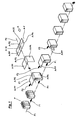
Figure 1 , it illustrates a first realization of the method subject of the present invention, hereby defined as basic method, which, as will be better understood below, can be used to form covers of different types and/or two-piece packages comprising said covers and a tray. - -In this first realization, the method is act to form a cover like an inverted "U" on top of a product P, in which said cover is formed by a blank-cover A that comprises, with respect to a longitudinal axis A-Y, at least a back panel A-PP, an upper panel A-PS and a front panel A-PA that are separated by means of transversal creases A-10 and A-20.
- -In the illustrated example, the products P, hereby illustrated as single lots of bottles, are translated from upstream to downstream along a first path P1 of products translation, for example driven by a translation force F1 acting directly on product P.
- -In particular, according to this basic method, following operations are performed: a) -the blank-cover A is placed in a folded configuration in the first zone Z1, upstream from the first path P1, above of and in front of the product P, with its back A-PP and upper A-PS panels horizontally coplanar placed above the upper side of the product P and with front panel A-PA vertically placed in front of the front side of the product P; b)-the blank-cover A is translated in this folded configuration from the first zone, Z1, downstream along the first path P1, as soon as the front side of the product P comes against and/or near the front panel A-PA of the blank A; c)-the back panel A-PP of the blank-cover A is folded against the back side of the product P while the product P and the blank-cover A are translated downstream along the first path P1.
- -With reference to operation a), preferably, the back panel A-PP and the upper panel A-PS are translated and placed at a level vertically slightly spaced with respect to the top of the product, thus obtaining an operative configuration in which the blank-cover A is positioned, stopped, suspended, transversally centred and vertically aligned above of and in front of the product P in motion, in such way that said product P can freely advance downstream against the front panel A-PA of this stationary blank-cover A without any interference between the top of the product P and the upper and back panels A-PS and A-PP, thus avoiding any possible overtumings of the bottles and/or avoiding any modifications in the shape of the lot.
- -With reference to operation b), preferably, the blank-cover A is translated downstream along the first path P1 as soon as the front side of product P comes against the front panel A-PA, or little before the front side of the product P comes against the front panel A-PA, thus avoiding and/or limiting the impact between the front side of the product P and the front panel A-PA of the blank-cover A for any of the aforementioned reasons.
- -Also with reference to operation b), it is preferable to translate the same blank-cover A from said zone Z1 along a path with a high-low, upstreamdownstream longitudinally orientation, in order to delicately place the suspended blank-cover A on top of the product P; alternatively, it is also possible to let the blank-cover A fall on top of the product P as soon as (or little before) the front side of the product P makes contact with the front panel A-PA.
- However, in both cases, the set obtained by P+A and placed downstream of the zone Z1 will comprise a product P partially covered by a blank-cover A correctly placed and centered, namely with the upper panel A-PS lying correctly on top of the upper side of the product P and with the front panel A-PA correctly placed against the front side of the product P.
- -Also with reference to the aforementioned basic method, it is preferable to translate the blank-cover A along the first path P1 with substantially the same linear forward speed with respect to the linear forward speed set for the product P, in order to limit and/or to avoid any relative movements between the blank-cover A and the product P.
- -Furthermore, in order to translate the product P and the blank-cover A downstream, it is preferable to apply a first force F1 directly on the product P and a second force F2 directly on the blank-cover A; in which said second force F2 will preferably be applied at first along the back edge of the back panel A-PP during the second operation b) and, after and/or during the folding towards the bottom of said back panel A-PP, i.e. third operation c), along the back edge of the upper panel A-PS.
- -Also with respect to
Figure 1 , preferably, in order to position the blank-cover A in the zone Z1, said blank-cover A is translated in a folded configuration along a first segment placed downstream of a second blank-translation path P2 in which said second path P2 will preferably be transversally aligned with respect to the first path P1. - -Furthermore, optionally, this second path P2 can also include a second segment upstream aligned, along which the blank-cover A would be folded from its original flat configuration to its folded configuration.
- -Also with respect to
Figure 1 , in order to obtain a continuous flow of products fit out with a cover, a continuous flow of product P is translated, preferably in a continuous motion, in a single succession and spaced to eachother along the first path P1 and, at the same time, a blank-cover A in a folded configuration can be inserted and placed in said zone Z1 in phase correlation and in a single succession, using for this insertion/positioning operation the time interval between two products P positioned in an immediate succession. - -With reference to
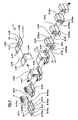
Figure 1A , it illustrates a second form of realization of the aforementioned basic method here used to form a quadrangular cover with lateral edges on top of the product P. - -In this second form of realization, the blank-cover, here indicated as A1, besides the aforementioned front, upper and back panels, A-PA, A-PS, A-PP, also includes closing flaps determined by means of creases and, more particularly, front closing flaps A-PAsx and A-PAdx placed on the opposite transversal ends of the front panel A-PA, upper closing flaps, A-PSsx, A-PSdx, placed on the opposite transversal ends of the upper panel A-PS, and back closing flaps, A-PPsx, A-PPdx, placed on the opposite transversal ends of the back panel A-PP.
- -In this case, and in a substantially similar-identical manner as the previous one, following operations are performed: a)-a blank-cover A1 is placed in the first zone Z1 upstream from the first path P1, in a folded configuration, above and in front of the product P, with its back A-PP and upper A-PS panels horizontally coplanar placed above the upper side of product P and with the front panel A-PA vertically placed in front of the front side of product P; b)-the blank-cover A1 is translated in the aforementioned folded configuration from the first zone, Z1, downstream along the first path P1, as soon as the front side of the product P comes against the front panel A-PA of the blank-cover A; afterwards, the other operations are executed in order to form the cover, i.e.: c1)-the closing flaps A-PAsx, A-PAdx, of the front panel A-PA of the blank-cover A1 are folded inwards against the product P; c2)-the closing flaps A-PPsx, A-PPdx, of the back panel A-PP of the blank-cover A1 are folded towards the bottom; c3)-the back panel A-PP of the blank-cover A1 is folded downwards and against the product P; c4)-the closing flaps A-PSsx, A-PSdx, of the upper panel A-PS of the blank-cover A1 are folded downwards and against the closing flaps A-PAsx, A-PPsx, A-PAdx, A-PPdx of the front panel A-PA and of the back panel A-PP.
- -With reference to the aforementioned method, please note that operations a) and b) are identical with respect to the operations a) and b) of the first realization, and that the operation c3) corresponds to the operation c) of the first realization.
- -Furthermore, it is preferable to join the closing flaps A-PSsx and A-PSdx of the upper panel A-PS with and above the closing flaps A-PAsx, A-PAdx, A-PPsx, A-PPdx, of the front panel A-PA and of the back panel A-PP; in which in order to obtain said joints adhesive is placed on the internal-lower side of the upper closing flaps, A-PSsx and A-PSdx, of the upper panel A-PS and/or on the external side of the front closing flaps, A-PAsx and A-PAdx, of the front panel A-PA, and/or on the external side of the back closing flaps, A-PPsx and A-PPdx, of the back panel A-PP, in which also preferably, said adhesive is applied during the translation of the blank-cover A along the first translation path P1.
- -In this way, as a consequence of the operations described above, a quadrangular cover will be formed on top of the product P, which will have an upper panel PS and four vertical edges on the four sides, in which said upper panel PS and the four vertical edges are joined together.
- -With reference to
Figure 2 , it illustrates a third realization of the basic method, in which the front closing flaps, A-PAsx, A-PAdx, the upper closing flaps, A-PSsx, A-PSdx, and the back closing flaps, A-PPsx, A-PPdx, are folded by means of a different operative method. - -In this case, the method is the same as described in the second realisation for operations a) and b) and, afterwards the following operations are performed: c1)-the closing flaps A-PSsx, A-PPdx, of the upper panel A-PS of the blank-cover A1 are folded downwards and against the product P; c2)-the closing flaps A-PPsx, A-PPdx, of the back panel A-PP of the blank-cover A1 are folded downwards; c3)-the back panel A-PP of the blank-cover A1 is folded downwards and against the product P, with closing flaps A-PPsx, A-PPdx, of the back panel A-PP placed over the closing flaps A-PSsx, A-PSdx of the upper panel A-PS.; c4)-the closing flaps A-PAsx, A-PAdx, of the front panel A-PA of the blank-cover A1 are folded inwards over the closing flaps A-PSsx, A-PSdx, of the upper panel A-PS.
- -With reference to the aforementioned method, please note that the operations a) and b) are identical with respect to the operations a) and b) of the first realization, and that the operation c3) corresponds to the operation c) of the first realization.
- -With reference to said third form of realization, it is preferable to join the front closing flaps A-PAsx and A-PAdx and the back closing flaps A-PPsx and A-PPdx, with and over the upper closing flaps, A-PSsx and A-PSdx, of the upper panel A-PS; in order to obtain said joints it is preferable to apply adhesive on the external upper side of the upper closing flaps, A-PSsx and A-PSdx, and/or on the internal side of the front closing flaps, A-PAsx and A-PAdx, and/or on the internal side of the back closing flaps, A-PPsx and A-PPdx.
- -Also in this case, said adhesive should preferably be applied during the translation of the blank cover A along the first translation path P1.
- -With reference to
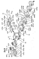
Figure 3 , it illustrates a fourth realization in which during the translating the product P along the first path P1, a tray is formed close to the base of the product P, in order to form a two-piece package with a cover shaped like an inverted "U" and a quadrangular tray with lateral edges close to the base of the product. - -In this context, as will be better understood below, the cover shaped like a "U" is formed by means of the blank-cover A from the first realization and following the same operative method.
- -With reference to the bottom tray, in this realization, it is formed by means of a second blank-tray B, which, with respect to a longitudinal extension axis B-Y, includes a front panel B-PA with closing flaps B-PAsx, B-PAdx, an inferior panel B-PI with closing flaps B-PIsx, B-PIdx, and a back panel B-PP with closing flaps B-PPsx, B-PPdx, all of these separated by means of creases.
- -With reference to the said
figure 3 , this fourth realization comprises the following operations: a)-the aforementioned blank-tray B is placed flat along the first translation path P1 of products P translation, with the inferior panel B-PI placed under the bottom side of the product P, the front panel B-PA placed downstream, and the back panel B-PP placed upstream; b)-in the first zone Z1, upstream from the first path P1, a blank-cover A is placed in a folded configuration above and in front of the product P, with its back A-PP and upper A-PS panels horizontally coplanar placed above the upper side of the product P and with the front panel A-PA vertically placed in front of the front side of the product P; c)-the blank-cover A is translated in this aforementioned folded configuration from the first zone, Z1, downstream along the first path P1, as soon as the front side of the product P comes near or against the front panel A-PA of the blank-cover A; d)-the back panel A-PP of the blank-cover A is folded against the back side of the product P, while the blank-tray B with product P and the blank-cover A are translated downstream along the first path P1; e)-operations are performed in order to fold the front panel B-PA, the back panel B-PP, and the closing flaps B-PAsx, B-PAdx, B-PIsx, B-PIdx, B-PPsx, and B-PPdx of the blank-tray B around the base of the product. - -With reference to the aforementioned method, please note that the operations b), c) and d) are substantially identical with respect to the operations a), b) and c) of the first realization.
- -Furthermore, in particular after operation d) of the aforementioned fourth realization, following operations are performed: e1)-the front panel B-PA of the blank-tray B is folded against the front panel A-PA of the blank-cover A; e2)-the closing flaps B-PPsx, B-PPdx, of the back panel B-PP of the blank-tray B are folded towards the top; e3)-the closing flaps B-PAsx, B-PAdx, of the front panel B-PA of the blank-tray B are folded inwards against the product P; e4)-the back panel B-PP of the blank-tray B is folded against the back panel A-PP of the blank-cover A, with the closing flaps B-PPsx, B-PPdx of the aforementioned back panel B-PP of the blank-tray B placed next to the lateral sides of the product P; e5)-the closing flaps B-PIsx and B-PIdx of the lower panel B-PI of the blank-tray B are folded upwards against the closing flaps B-PAsx, B-PPsx and B-PAdx, B-PPdx, of the front panel B-PA and of the back panel B-PP of the blank-tray B;
- With respect to the
Figure 3A , it illustrates a fifth realization during which while translating the product P along the first path P1, a quadrangular cover with lateral edges is formed on top of the product P and a quadrangular tray with lateral edges is formed around the base of said product. - -In this context, as will be better understood below, the cover is formed by means of the blank-cover A1 from the second realization and by using the basic method from the first realization, while the bottom tray is formed by using a blank-tray B like in the previous fourth realization.
- -In particular, said fifth realization comprises the following operations: a)-the aforementioned blank-tray B is placed flat along the first translation path P1 of products P translation, with the lower panel B-PI placed under the bottom side of the product P, the front panel B-PA placed downstream, and the back panel B-PP placed upstream; b)-in the first zone Z1, upstream from the first path P1, a blank-cover A is placed in a folded configuration above and in front of the product P, with its back A-PP and upper A-PS panels horizontally coplanar placed above the upper side of the product P and with the front panel A-PA vertically placed in front of the front side of the product P; c)-the blank-cover A is translated in the aforementioned folded configuration from the first zone, Z1, downstream along the first path P1, as soon as the front side of the product P placed over the inferior panel B-PI of the blank-tray B comes near or against the front panel A-PA of the blank-cover A; d)-the back panel A-PP of the blank-cover A is folded against the back side of the product P, while the blank-tray B, together with the product P and the blank-cover A, are translated furtherly downstream along the first path P1; e)-the operations of folding and forming of the quadrangular cover with lateral edges and the quadrangular tray with lateral edges are then executed.
- -With reference to the aforementioned method, please note that the operations b), c) and d) are substantially identical with respect to the operations a), b) and c) of the first realization.
- -Furthermore, in particular, preferably after the operation d) of this aforementioned fifth realization, the following operations are performed: e1)-the closing flaps A-PAsx, A-PAdx, of the front panel A-PA of the blank-cover A are folded against the product P; e2)-the closing flaps A-PPsx, A-PPdx, of the back panel A-PP of the blank-cover A are folded downwards; e3)-the front panel B-PA of the blank-tray B is folded against the front panel A-PA of the blank-cover A; e4)-the back panel A-PP of the blank-cover A is folded towards the bottom and against the product P, with closing flaps A-PPsx, A-PPdx, of the back panel A-PP placed on the sides of the product P; e5)-the closing flaps B-PPsx, B-PPdx, of the back panel B-PP of the blank-tray B are folded towards the top; e6)-the closing flaps B-PAsx, B-PAdx, of the front panel B-PA of the blank-tray B are folded against the respective closing flaps A-PAsx, A-PAdx, of the front panel A-PA of the blank-cover A; e7)-the back panel B-PP of the blank-tray B is folded against the back panel A-PP of the blank-cover A, with the closing flaps B-PPsx, B-PPdx of the aforementioned back panel B-PP of the blank-tray B placed next to the closing flaps, A-PPsx and A-PPdx, of the back panel A-PP of the blank-cover A; e8)-the closing flaps A-PSsx, A-PSdx, of the upper panel A-PS of the blank-cover A are folded towards the bottom and against the closing flaps A-PAsx, A-PPsx, A-PAdx, A-PPdx of the front and back panels A-PA and A-PP of the blank-cover A; e9)-the closing flaps B-PIsx and B-PIdx of the lower panel B-PI of the blank-tray B are folded upwards against the closing flaps B-PAsx, B-PPsx, B-PAdx, and B-PPdx of the front and back panels B-PA and B-PP of the blank-tray B.
- -With reference to the fourth and the fifth realization, it is optionally possible to join together the cover with respect to the tray, preferably by unions that should have a calibrated resistance for an easy detachment in order to facilitate the removal of the cover, so that the product lot could be exhibited on its tray at the points of sale and also easily removed from the tray in order to be bought.
- -In this context, it is preferable for the front panel A-PA to be joined to the front panel B-PA, by applying the adhesive C1, C2, on the external side of the front panel A-PA and/or on the internal side of the front panel B-PA, in those zones where these two sides will be joined together and where the adhesive will preferably be applied on during the translation of the blanks along said first P1 or second P2 translation paths.
- -Furthermore, and in the same manner, it is also possible to join together the back panel A-PP with the back panel B-PP, by using the adhesive C3, C4, applied on the external side of the back panel A-PP and/or on the internal side of the back panel B-PP, preferably also along the first or second translation path P1, P2.
- -By means of these unions, it is for example sufficient to insert a hand from up to down between the two joint panels in order to obtain a detachment and therefore an immediate removal of the cover.
- -With reference to the above said, the present invention also concerns a cover shaped like an inverted "U" or a quadrangular cover with lateral edges obtained through one of the above described methods related to this matter, as well as a two-piece package including a cover and a tray obtained through the use of one of these methods.
- -The descriptions of the aforementioned methods are given purely as an example and are not to be considered a restriction and, therefore, it is obvious that suggested modifications and/or variations could be made to them during the practice and/or by the use of these methods, anyway within the scope of the following claims.
Claims (37)
- Method to form a cover on top of a product (P), in which said cover is formed by a blank-cover (A / A1) that includes, with respect to a longitudinal axis (A-Y), at least a back panel (A-PP), an upper panel (A-PS), and a front panel (A-PA) that are separated by means of transversal creases (A-10, A-20); in which the product (P) is translated from upstream to downstream along a first products translation path (P1), characterized by the fact that it comprises the following operations: a)-in the first zone (Z1), along of the first path (P1), a blank-cover (A / A1) is placed in a folded configuration above of and in front of the product (P), with the back (A-PP) and upper (A-PS) panels placed horizontally coplanar above the upper side of the product (P) and with the front panel (A-PA) placed vertically in front of the front side of the product (P); b)-the blank-cover (A / A1) is translated in the aforementioned folded configuration from the first zone (Z1) downstream along the first path (P1), as soon as or a short time before the front side of the product (P) comes against the front panel (A-PA) of the blank-cover (A), and by the fact that during the execution of the operation b) a first force (F1) is directly applied on the product (P) to translate said product (P) downstream, and a different second force (F2) is directly applied on the blank-cover (A / A1) to translate said blank-cover (A / A1) downstream.
- Method according to claim 1, characterized by the fact that after the operation b) is executed a further operation c) in which the back panel (A-PP) of the blank-cover (A / A1) is folded against the back side of the product (P) while the product (P) and the blank-cover (A / A1) are translated downstream along the first path (P1).
- Method according to claim 1 or 2, characterized by the fact that the blank-cover (A / A1) is translated at a linear forward speed that is substantially equal to the linear forward speed imposed on the product (P).
- Method according to claim 2 or 3, characterized by the fact that during the execution of the operation c) a first force (F1) is directly applied on the product (P) to translate said product (P) downstream, and a different second force (F2) is directly applied on the blank-cover (A / A1) to fold the back panel (A-PP) downwards and to move downstream the same blank-cover (A / A1).
- Method according to one of the claims from 1 to 4, characterized by the fact that for the execution of the operation a) the blank-cover (A / A1) is translated in a folded configuration along a second blank-cover (A / A1) translation path (P2).
- Method according to claim 5, characterized by the fact that said second blank-cover (A / A1) translation path (P2) is inclined and/or transversally oriented with respect to the first path (P1).
- Method according to one of the claims from 1 to 6, characterized by the fact that for the execution of the operation a) the blank-cover (A / A1) is translated in a folded configuration along the second path (P2) with the upper panel (A-PS) and the back panel (A-PP) placed above the top of the product (P).
- Method according to one of the claims from 1 to 7, characterized by the fact that before of the operation a) the blank-cover (A / A1) is folded from its flat configuration to its folded configuration.
- Method according to claim 8, characterized by the fact that the blank-cover (A / A1) is folded from its flat configuration to its folded configuration along a segment of the aforementioned second blank-cover (A / A1) translation path (P2).
- Method according to one of the previous claims, characterized by the fact that a products flow is translated in a continuous motion and in a single spaced succession along said first path (P1) and by the fact that in said zone (Z1) are inserted the aforementioned blank-covesr (A/A1) in single succession by means of the existing space between two successive products (P).
- Method according to one of the previous claims, characterized by the fact that said blank-cover (A / A1) further comprises: >-front closing flaps (A-PAsx, A-PAdx) placed on the opposite transversal ends of the front panel (A-PA); >-upper closing flaps (A-PSsx, A-PSdx) placed on the opposite transversal ends of the upper panel (A-PS); >-back closing flaps (A-PPsx, A-PPdx) placed on the opposite transversal ends of the back panel (A-PP); and by the fact that after the operation b) the following operations are comprised: c1)-the closing flaps (A-PAsx, A-PAdx) of the front panel (A-PA) of the blank-cover (A1) are folded inwards against the product (P); c2)-the closing flaps (A-PPsx, A-PPdx) of the back panel (A-PP) of the blank-cover (A1) are folded downwards; c3)-the back panel (A-PP) of the blank-cover (A1) is folded downwards against the product (P); c4)-the closing flaps (A-PSsx, A-PSdx) of the upper panel (A-PS) of the blank-cover (A1) are folded downwards against the closing flaps (A-PAsx, A-PPsx, A-PAdx, A-PAdx) of the front panel (A-PA) and of the back panel (A-PP).
- Method according to claim 11, characterized by the fact that the closing flaps (A-PSsx, A-PSdx) of the upper panel (A-PS) of the blank-cover (A1) are joined together with and over the closing flaps (A-PAsx, A-PAdx, A-PPsx, A-PPdx) of the front panel (A-PA) and of the back panel (A-PP) of said blank-cover (A1).
- Method according to claim 12, characterized by the fact that in order to obtain said joints adhesive is placed on the internal side of the closing flaps (A-PSsx, A-PSdx) of the upper panel (A-PS) of the blank-cover (A1).
- Method according claim 12 or 13, characterized by the fact that in order to obtain said joints adhesive is placed on the external side of the closing flaps (A-PAsx, A-PAdx) of the front panel (A-PA) of the blank-cover (A1).
- Method according to one of the claims from 12 to 14, characterized by the fact that in order to obtain said joints adhesive is placed on the external side of the closing flaps (A-PPsx, A-PPdx) of the back panel (A-PP) of the blank-cover (A1).
- Method according to one of the claims from 13 to 15, characterized by the fact that said adhesive is applied during the translation of the blank-cover (A1) along the first translation path (P1).
- Method according to one of the claims from 1 to 10, characterized by the fact that said blank-cover (A / A1) further comprises: >-front closing flaps (A-PAsx, A-PAdx) placed on the opposite transversal ends of the front panel (A-PA); >-upper closing flaps (A-PSsx, A-PSdx) placed on the opposite transversal ends of the upper panel (A-PS); >-back closing flaps (A-PPsx, A-PPdx) placed on the opposite transversal ends of the back panel (A-PP), and by the fact that after the operation b) the following operations are comprised: c1)-the closing flaps (A-PSsx, A-PSdx) of the upper panel (A-PS) of the blank cover (A1) are folded downwards against product (P); c2)-the closing flaps (A-PPsx, A-PPdx) of the back panel (A-PP) of the blank-cover (A1) are folded downwards; c3)-the back panel (A-PP) of the blank-cover (A1) is folded downwards against the product (P), with the closing flaps (A-PPsx, A-PPdx) of the back panel (A-PP) placed over the closing flaps (A-PSsx, A-PSdx) of the upper panel (A-PS); c4)-the closing flaps (A-PAsx, A-PAdx) of the front panel (A-PA) of the blank-cover (A1) are folded inwards over the closing flaps (A-PSsx, A-PSdx) of the upper panel (A-PS).
- Method according to claim 17, characterized by the fact that the closing flaps (A-PAsx, A-PAdx, A-PPsx, A-PPdx) of the front panel (A-PA) and of the back panel (A-PP) of the blank-cover (A1) are joined together with and over the closing flpas (A-PSsx, A-PSdx) of the upper panel (A-PS) of said blank-cover (A1).
- Method according to claim 18, characterized by the fact that in order to obtain said joints adhesive is placed on the external side of the closing flaps (A-PSsx, A-PSdx) of the upper panel (A-PS) of the blank-cover (A1).
- Method according claim 18 or 19, characterized by the fact that in order to obtain said joints adhesive is placed on the internal side of the closing flaps (A-PAsx, A-PAdx) of the front panel (A-PA) of the blank-cover (A1).
- Method according to one of the claims from 18 to 20, characterized by the fact that in order to obtain said joints adhesive is placed on the internal side of the closing flaps (A-PPsx, A-PPdx) of the back panel (A-PP) of the blank-cover (A1).
- Method according to one of the claims from 19 to 21, characterized by the fact that said adhesive is applied during the translation of the blank-cover (A1) along the first translation path (P1).
- Method according to one of the preceding claims, characterized by the fact that along said first translation path (P1) further operations are performed in order to insert a blank-tray (B) under the bottom side of the product (P) and in order to fold said second blank-tray (B) around the base of the product (P) in order to form a two-piece package including a cover formed according to one of the previous claims and a tray.
- Method according to claim 23, characterized by the fact that said blank-tray (B) comprises, with respect to a longitudinal axis (B-Y), at least a front panel (B-PA), an inferior panel (B-PI) and a back panel (B-PP) separated by means of creases, and by the fact that said blank-tray (B) is placed in a flat configuration along the first translation path (P1) of products (P) with the lower panel (B-PI) placed under the bottom side of the product (P), the front panel (B-PA) placed downstream, and the back panel (B-PP) placed upstream.
- Method according to one of the preceding claims, characterized by the fact that during the translation of the product (P) along the first path (P1) is formed a two-piece package, in which said two-piece package comprises a cover shaped like an inverted "U" on the top of the product (P) and a quadrangular tray with lateral edges close to the base of the product, in which said cover is formed by means of a blank-cover (A) which comprises, with respect to a longitudinal axis (A-Y), at least a back panel (A-PP), an upper panel (A-PS), and a front panel (A-PA) separated by means of creases, in which said tray is formed by a second blank-tray (B) which comprises, with respect to a longitudinal axis (B-Y) and separated by means of creases, at least a front panel (B-PA) with closing flaps (B-PAsx, B-PAdx), a lower panel (B-PI) with closing flaps (B-Plsx, B-PIdx), a back panel (B-PP) with closing flaps (B-PPsx, B-PPdx), and characterized by the fact that said method comprises the following operations: a)-the said blank-tray (B) is placed flat along the first translation path (P1) of products (P) with the lower panel (B-PI) placed under the bottom side of the product (P), the front panel (B-PA) placed downstream, and the back panel (B-PP) placed upstream; b)-in the first zone (Z1), placed upstream of the first path (P1), a blank cover (A) is placed in a folded configuration above of and in front of the product (P), with its back (A-PP) and upper (A-PS) panels placed horizontally coplanar to eachother above the upper side of the product (P) and with front panel (A-PA) placed vertically in front of the front side of the product (P); c)-the blank-cover (A) is translated in this folded configuration from said first zone (Z1) downstream along the first path (P1) as soon as the front side of the product (P) placed over the lower panel (B-PI) of the blank-tray (B) comes against or near the front panel (A-PA) of the blank-cover (A); d)-the back panel (A-PP) of the blank-cover (A) is folded against the back side of the product (P) while the blank-tray (B) together with the product (P) and the blank-cover (A) are translated furtherly downstream along the first path (P1); e)-operations are performed in order to fold the front panel (B-PA), the back panel (B-PP), and the closing flaps (B-PAsx, B-PAdx, B-PIsx, B-PIdx, B-PPsx, and B-PPdx) of the blank-tray (B) around the base of the product (P).
- Method according to claim 25, characterized by the fact that after the operation d) following operations are performed: e1)-the front panel (B-PA) of the blank-tray (B) is folded against the front panel (A-PA) of the blank-cover (A); e2)-the closing flaps (B-PPsx, B-PPdx) of the back panel (B-PP) of the blank-tray (B) are folded upwards; e3)-the closing flaps (B-PAsx, B-PAdx) of the front panel (B-PA) of the blank-tray (B) are folded inwards against the product (P); e4)-the back panel (B-PP) of the blank-tray (B) is folded against the back panel (A-PP) of the blank-cover (A), with the closing flaps (B-PPsx, B-PPdx) of said back panel (B-PP) of the blank-tray (B) placed next to the lateral sides of the product (P); e5)-the closing flaps (B-Plsx and B-PIdx) of the lower panel (B-PI) of the blank-tray (B) are folded upwards against the closing flaps (B-PAsx, B-PPsx, B-PAdx, B-PPdx) of the front panel (B-PA) and of the back panel (B-PP) of the blank-tray (B).
- Method according to one of the claims from 1 to 24, characterized by the fact that during the translation of the product (P) along the first path (P1) is formed a two-piece package, in which said two-piece package comprises a quadrangular cover with lateral edges on top of the product (P) and a quadrangular tray with lateral edges close to the base of the product (P), in which said cover is formed by means of a first blank-cover (A1) that comprises, separated by means of creases and with respect to a longitudinal axis (A-Y), at least a front panel (A-PA) with its corresponding front closing flaps (A-PAsx, A-PAdx), an upper panel (A-PS) with its corresponding upper closing flaps (A-PSsx, A-PSdx), and a back panel (A-PP) with its corresponding back closing flaps (A-PPsx, A-PPdx); in which said tray is formed by means of a second blank tray (B) that comprises, separated by means of creases and with respect to a longitudinal axis (B-Y), at least a front panel (B-PA) with closing flaps (B-PAsx, B-PAdx), a lower panel (B-PI) with closing flaps (B-Plsx, B-PIdx), a back panel (B-PP) with closing flaps (B-PPsx, B-PPdx), and characterized by the fact that said method comprises the following operations: a)-the said blank-tray (B) is placed flat along the first path (P1) of product (P) translation with the lower panel (B-PI) placed under the bottom side of the product (P), the front panel (B-PA) placed downstream, and the back panel (B-PP) placed upstream; b)-in the first zone (Z1) placed upstream of the first path (P1), the blank-cover (A) is placed in a folded configuration above of and in front of the product (P), with its back (A-PP) and upper (A-PS) panels horizontally coplanar to eachother placed above the upper side of the product (P) and with front panel (A-PA) placed vertically in front of the front side of the product (P); c)-the blank-cover (A) is translated in this folded configuration from the first zone (Z1) downstream along the first path (P1) as soon as the front side of product (P) placed over the inferior panel (B-PI) of the blank-tray (B) comes against or near the front panel (A-PA) of the blank-cover (A); d)-the back panel (A-PP) of the blank-cover (A) is folded against the back side of the product (P) while the blank-tray (B), together with the product (P) and the blank-cover (A), are translated furtherly downstream along the first path (P1); e)-the operations for folding the further panels and the closing flaps are executed in order to complete the forming of the quadrangular cover with lateral edges and the quadrangular tray with lateral edges.
- Method according to claim 27, characterized by the fact that after the operation d) the following operations are performed: e1)-the closing flaps (A-PAsx, A-PAdx) of the front panel (A-PA) of the blank-cover (A1) are folded against the product (P); e2)-the closing flaps (A-PPsx, A-PPdx) of the back panel (A-PP) of the blank-cover (A1) are folded downwards; e3)-the front panel (B-PA) of the blank-tray (B) is folded against the front panel (A-PA) of the blank-cover (A); e4)-the back panel (A-PP) of the blank-cover (A1) is folded downwards against the product (P) with the closing flaps (A-PPsx, A-PPdx) of the back panel (A-PP) placed on the sides of the product (P); e5)-the closing flaps (B-PPsx, B-PPdx) of the back panel (B-PP) of the blank-tray (B) are folded upwards; e6)-the closing flaps (B-PAsx, B-PAdx) of the front panel (B-PA) of the blank-tray (B) are folded against the respective closing flaps (A-PAsx, A-PAdx) of the front panel (A-PA) of the blank-cover (A1); e7)-the back panel (B-PP) of the blank-tray (B) is folded against the back panel (A-PP) of the blank-cover (A1) with the closing flaps (B-PPsx, B-PPdx) of said back panel (B-PP) of the blank-tray (B) placed next to the closing flaps (A-PPsx, A-PPdx) of the back panel (A-PP) of the blank-cover (A1); e8)-the closing flaps (A-PSsx, A-PSdx) of the upper panel (A-PS) of the blank-cover (A) are folded downwards and against the closing flaps (A-PAsx, A-PPsx, A-PAdx, A-PAdx) of the front and back panels (A-PA, A-PP); e9)-the closing flaps (B-Plsx, B-PIdx) of the lower panel (B-PI) of the blank-tray (B) are folded upwards against the closing flaps (B-PAsx, B-PPsx, B-PAdx, and B-PPdx) of the front and back panels (B-PA, B-PP) of the blank-tray (B).
- Method according to one of the claims from 25 to 28, characterized by the fact that is provided to join together the cover with the tray.
- Method according to claim 29, characterized by the fact that said junction has a resistance that is calibrated for an easy detachment.
- Method according to one of the claims from 25 to 30, characterized by the fact that the front panel (A-PA) of the blank-cover (A) and the front panel (B-PA) of the blank-tray (B) are joined together.
- Method according to claim 31, characterized by the fact that said junction is obtained by using an adhesive (C2) applied on the external side of the front panel (A-PA) of the blank cover (A) and/or an adhesive (C1) applied on the intemal side of the front panel (B-PA) of the blank-tray (B).
- Method according to one of the claims from 25 to 32, characterized by the fact that the back panel (A-PP) of the blank-cover (A) and the back panel (B-PP) of the blank-tray (B) are joined together.
- Method according to claim 33, characterized by the fact that said junction is obtained by using an adhesive (C3) applied on the external side of the back panel (A-PP) of the blank-cover (A) and/or an adhesive (C4) applied on the internal side of the back panel (B-PP) of the blank-tray (B).
- Method according to one of the claims from 32 to 34, characterized by the fact that said adhesive is applied during the translation of the blank-cover (A/A1) and of the blank-tray (B) along the first translation path (P1).
- Cover obtained according to one of the claims from 1 to 35.
- Two-piece package including a cover and a tray obtained according to one of the claims from 25 to 35.
Applications Claiming Priority (1)
| Application Number | Priority Date | Filing Date | Title |
|---|---|---|---|
| ITBO20070132 ITBO20070132A1 (en) | 2007-02-28 | 2007-02-28 | METHOD FOR FORMING A LID ON THE SUMMIT OF A PRODUCT AND / OR A PACKAGE IN TWO PIECES INCLUDING THAT COVER AND A TRAY |
Publications (3)
| Publication Number | Publication Date |
|---|---|
| EP1982918A2 EP1982918A2 (en) | 2008-10-22 |
| EP1982918A3 EP1982918A3 (en) | 2012-07-04 |
| EP1982918B1 true EP1982918B1 (en) | 2013-11-20 |
Family
ID=39720671
Family Applications (1)
| Application Number | Title | Priority Date | Filing Date |
|---|---|---|---|
| EP08101874.9A Not-in-force EP1982918B1 (en) | 2007-02-28 | 2008-02-22 | Method to form a cover on top of a product and/or to form a two-piece package comprising said cover and a tray |
Country Status (2)
| Country | Link |
|---|---|
| EP (1) | EP1982918B1 (en) |
| IT (1) | ITBO20070132A1 (en) |
Families Citing this family (2)
| Publication number | Priority date | Publication date | Assignee | Title |
|---|---|---|---|---|
| DE102009003740A1 (en) * | 2009-04-03 | 2010-10-07 | Meypack Verpackungssystemtechnik Gmbh | Method for producing a packaging box, and packaging machine |
| DE102018203180A1 (en) * | 2018-03-02 | 2019-09-05 | Krones Aktiengesellschaft | Packaging device for articles and methods for packaging articles |
Family Cites Families (3)
| Publication number | Priority date | Publication date | Assignee | Title |
|---|---|---|---|---|
| DE4018140C1 (en) * | 1990-06-06 | 1991-09-26 | Kisters Maschinenbau Gmbh, 4190 Kleve, De | |
| DE19712787A1 (en) * | 1997-03-26 | 1998-10-01 | Schrutt Gmbh | Appts to fit a cover to a bottle carton |
| IT1315198B1 (en) * | 1999-07-09 | 2003-02-03 | Zambelli Alberto | CORRUGATED CARDBOARD BOX FOR THE PACKAGING OF PRODUCTS AND EDAPPARATED METHOD FOR THE REALIZATION AND FOR THE USE ON INDUSTRIAL SCALE OF |
-
2007
- 2007-02-28 IT ITBO20070132 patent/ITBO20070132A1/en unknown
-
2008
- 2008-02-22 EP EP08101874.9A patent/EP1982918B1/en not_active Not-in-force
Also Published As
| Publication number | Publication date |
|---|---|
| EP1982918A2 (en) | 2008-10-22 |
| EP1982918A3 (en) | 2012-07-04 |
| ITBO20070132A1 (en) | 2008-09-01 |
Similar Documents
| Publication | Publication Date | Title |
|---|---|---|
| EP1997736A2 (en) | Method to form a two-piece package comprising a cover and a tray and package obtained by this method | |
| US11305903B2 (en) | Box template folding process and mechanisms | |
| CA2043941C (en) | Packaging system | |
| JP5869304B2 (en) | Hinged lid package and packaging method and packaging machine for manufacturing hinged lid package | |
| RU2631173C2 (en) | Preassembled open box with automatically generated supports for stacking | |
| US7998049B1 (en) | Cartoner for cartons having concave sides | |
| CN108883845A (en) | For making the device and method of the pediment shaping surface of the package with inclination pediment | |
| US20080081754A1 (en) | Container forming machines and methods | |
| CN103582600A (en) | Carton for packaging articles, blank and method for forming same | |
| EP1982918B1 (en) | Method to form a cover on top of a product and/or to form a two-piece package comprising said cover and a tray | |
| US2701938A (en) | Method and apparatus for packaging cans and bottles in carrier cartons | |
| WO2018002791A1 (en) | Package for containing and displaying precious and luxury products or items, such as perfumes, creams, alcoholic products, high-end cosmetics, high fashion accessories, jewelry and/or the like | |
| CN108473245A (en) | Retail display box | |
| WO2025132411A1 (en) | Process and machine for packaging, and related packaging | |
| AU2012345486B2 (en) | Method of and apparatus for erecting containers | |
| US7024838B2 (en) | Packaging apparatus | |
| EP1954566B1 (en) | Machine for raising planar articles | |
| US3760555A (en) | Packaging machine | |
| EP1531032B1 (en) | Assembly device for wooden boxes and the assembly procedure for the wooden boxes | |
| US2057782A (en) | Apparatus for stapling containers | |
| GB2229710A (en) | Packages formed from blanks | |
| GB2473963A (en) | Packaging tray | |
| ITBO20080512A1 (en) | PACKAGING EQUIPMENT. | |
| GB2554124A (en) | Package for containing and displaying precious and luxury products or items, such as perfumes, creams, alcoholic products, high-end cosmetics, | |
| GB2495478A (en) | Conveying and collapsing crates |
Legal Events
| Date | Code | Title | Description |
|---|---|---|---|
| PUAI | Public reference made under article 153(3) epc to a published international application that has entered the european phase |
Free format text: ORIGINAL CODE: 0009012 |
|
| AK | Designated contracting states |
Kind code of ref document: A2 Designated state(s): AT BE BG CH CY CZ DE DK EE ES FI FR GB GR HR HU IE IS IT LI LT LU LV MC MT NL NO PL PT RO SE SI SK TR |
|
| AX | Request for extension of the european patent |
Extension state: AL BA MK RS |
|
| PUAL | Search report despatched |
Free format text: ORIGINAL CODE: 0009013 |
|
| RIC1 | Information provided on ipc code assigned before grant |
Ipc: B65B 5/02 20060101AFI20120515BHEP Ipc: B65B 21/24 20060101ALI20120515BHEP |
|
| AK | Designated contracting states |
Kind code of ref document: A3 Designated state(s): AT BE BG CH CY CZ DE DK EE ES FI FR GB GR HR HU IE IS IT LI LT LU LV MC MT NL NO PL PT RO SE SI SK TR |
|
| AX | Request for extension of the european patent |
Extension state: AL BA MK RS |
|
| RIC1 | Information provided on ipc code assigned before grant |
Ipc: B65B 21/24 20060101ALI20120531BHEP Ipc: B65B 5/02 20060101AFI20120531BHEP |
|
| 17P | Request for examination filed |
Effective date: 20121220 |
|
| AKX | Designation fees paid |
Designated state(s): AT BE BG CH CY CZ DE DK EE ES FI FR GB GR HR HU IE IS IT LI LT LU LV MC MT NL NO PL PT RO SE SI SK TR |
|
| GRAP | Despatch of communication of intention to grant a patent |
Free format text: ORIGINAL CODE: EPIDOSNIGR1 |
|
| RIN1 | Information on inventor provided before grant (corrected) |
Inventor name: GAMBETTI, CRISTINA |
|
| GRAP | Despatch of communication of intention to grant a patent |
Free format text: ORIGINAL CODE: EPIDOSNIGR1 |
|
| INTG | Intention to grant announced |
Effective date: 20130612 |
|
| GRAS | Grant fee paid |
Free format text: ORIGINAL CODE: EPIDOSNIGR3 |
|
| GRAA | (expected) grant |
Free format text: ORIGINAL CODE: 0009210 |
|
| AK | Designated contracting states |
Kind code of ref document: B1 Designated state(s): AT BE BG CH CY CZ DE DK EE ES FI FR GB GR HR HU IE IS IT LI LT LU LV MC MT NL NO PL PT RO SE SI SK TR |
|
| REG | Reference to a national code |
Ref country code: GB Ref legal event code: FG4D |
|
| REG | Reference to a national code |
Ref country code: CH Ref legal event code: EP |
|
| REG | Reference to a national code |
Ref country code: AT Ref legal event code: REF Ref document number: 641440 Country of ref document: AT Kind code of ref document: T Effective date: 20131215 |
|
| REG | Reference to a national code |
Ref country code: IE Ref legal event code: FG4D |
|
| REG | Reference to a national code |
Ref country code: DE Ref legal event code: R096 Ref document number: 602008028789 Country of ref document: DE Effective date: 20140116 |
|
| REG | Reference to a national code |
Ref country code: NL Ref legal event code: VDEP Effective date: 20131120 |
|
| REG | Reference to a national code |
Ref country code: AT Ref legal event code: MK05 Ref document number: 641440 Country of ref document: AT Kind code of ref document: T Effective date: 20131120 |
|
| REG | Reference to a national code |
Ref country code: LT Ref legal event code: MG4D |
|
| PG25 | Lapsed in a contracting state [announced via postgrant information from national office to epo] |
Ref country code: FI Free format text: LAPSE BECAUSE OF FAILURE TO SUBMIT A TRANSLATION OF THE DESCRIPTION OR TO PAY THE FEE WITHIN THE PRESCRIBED TIME-LIMIT Effective date: 20131120 Ref country code: SE Free format text: LAPSE BECAUSE OF FAILURE TO SUBMIT A TRANSLATION OF THE DESCRIPTION OR TO PAY THE FEE WITHIN THE PRESCRIBED TIME-LIMIT Effective date: 20131120 Ref country code: LT Free format text: LAPSE BECAUSE OF FAILURE TO SUBMIT A TRANSLATION OF THE DESCRIPTION OR TO PAY THE FEE WITHIN THE PRESCRIBED TIME-LIMIT Effective date: 20131120 Ref country code: NO Free format text: LAPSE BECAUSE OF FAILURE TO SUBMIT A TRANSLATION OF THE DESCRIPTION OR TO PAY THE FEE WITHIN THE PRESCRIBED TIME-LIMIT Effective date: 20140220 Ref country code: NL Free format text: LAPSE BECAUSE OF FAILURE TO SUBMIT A TRANSLATION OF THE DESCRIPTION OR TO PAY THE FEE WITHIN THE PRESCRIBED TIME-LIMIT Effective date: 20131120 Ref country code: HR Free format text: LAPSE BECAUSE OF FAILURE TO SUBMIT A TRANSLATION OF THE DESCRIPTION OR TO PAY THE FEE WITHIN THE PRESCRIBED TIME-LIMIT Effective date: 20131120 Ref country code: IS Free format text: LAPSE BECAUSE OF FAILURE TO SUBMIT A TRANSLATION OF THE DESCRIPTION OR TO PAY THE FEE WITHIN THE PRESCRIBED TIME-LIMIT Effective date: 20140320 |
|
| PG25 | Lapsed in a contracting state [announced via postgrant information from national office to epo] |
Ref country code: BE Free format text: LAPSE BECAUSE OF FAILURE TO SUBMIT A TRANSLATION OF THE DESCRIPTION OR TO PAY THE FEE WITHIN THE PRESCRIBED TIME-LIMIT Effective date: 20131120 Ref country code: ES Free format text: LAPSE BECAUSE OF FAILURE TO SUBMIT A TRANSLATION OF THE DESCRIPTION OR TO PAY THE FEE WITHIN THE PRESCRIBED TIME-LIMIT Effective date: 20131120 Ref country code: LV Free format text: LAPSE BECAUSE OF FAILURE TO SUBMIT A TRANSLATION OF THE DESCRIPTION OR TO PAY THE FEE WITHIN THE PRESCRIBED TIME-LIMIT Effective date: 20131120 Ref country code: AT Free format text: LAPSE BECAUSE OF FAILURE TO SUBMIT A TRANSLATION OF THE DESCRIPTION OR TO PAY THE FEE WITHIN THE PRESCRIBED TIME-LIMIT Effective date: 20131120 |
|
| PG25 | Lapsed in a contracting state [announced via postgrant information from national office to epo] |
Ref country code: PT Free format text: LAPSE BECAUSE OF FAILURE TO SUBMIT A TRANSLATION OF THE DESCRIPTION OR TO PAY THE FEE WITHIN THE PRESCRIBED TIME-LIMIT Effective date: 20140320 |
|
| PG25 | Lapsed in a contracting state [announced via postgrant information from national office to epo] |
Ref country code: EE Free format text: LAPSE BECAUSE OF FAILURE TO SUBMIT A TRANSLATION OF THE DESCRIPTION OR TO PAY THE FEE WITHIN THE PRESCRIBED TIME-LIMIT Effective date: 20131120 |
|
| REG | Reference to a national code |
Ref country code: DE Ref legal event code: R097 Ref document number: 602008028789 Country of ref document: DE |
|
| PG25 | Lapsed in a contracting state [announced via postgrant information from national office to epo] |
Ref country code: RO Free format text: LAPSE BECAUSE OF FAILURE TO SUBMIT A TRANSLATION OF THE DESCRIPTION OR TO PAY THE FEE WITHIN THE PRESCRIBED TIME-LIMIT Effective date: 20131120 Ref country code: SK Free format text: LAPSE BECAUSE OF FAILURE TO SUBMIT A TRANSLATION OF THE DESCRIPTION OR TO PAY THE FEE WITHIN THE PRESCRIBED TIME-LIMIT Effective date: 20131120 Ref country code: CZ Free format text: LAPSE BECAUSE OF FAILURE TO SUBMIT A TRANSLATION OF THE DESCRIPTION OR TO PAY THE FEE WITHIN THE PRESCRIBED TIME-LIMIT Effective date: 20131120 Ref country code: PL Free format text: LAPSE BECAUSE OF FAILURE TO SUBMIT A TRANSLATION OF THE DESCRIPTION OR TO PAY THE FEE WITHIN THE PRESCRIBED TIME-LIMIT Effective date: 20131120 |
|
| PLBE | No opposition filed within time limit |
Free format text: ORIGINAL CODE: 0009261 |
|
| STAA | Information on the status of an ep patent application or granted ep patent |
Free format text: STATUS: NO OPPOSITION FILED WITHIN TIME LIMIT |
|
| PG25 | Lapsed in a contracting state [announced via postgrant information from national office to epo] |
Ref country code: MC Free format text: LAPSE BECAUSE OF FAILURE TO SUBMIT A TRANSLATION OF THE DESCRIPTION OR TO PAY THE FEE WITHIN THE PRESCRIBED TIME-LIMIT Effective date: 20131120 Ref country code: LU Free format text: LAPSE BECAUSE OF FAILURE TO SUBMIT A TRANSLATION OF THE DESCRIPTION OR TO PAY THE FEE WITHIN THE PRESCRIBED TIME-LIMIT Effective date: 20140222 Ref country code: DK Free format text: LAPSE BECAUSE OF FAILURE TO SUBMIT A TRANSLATION OF THE DESCRIPTION OR TO PAY THE FEE WITHIN THE PRESCRIBED TIME-LIMIT Effective date: 20131120 |
|
| REG | Reference to a national code |
Ref country code: CH Ref legal event code: PL |
|
| 26N | No opposition filed |
Effective date: 20140821 |
|
| GBPC | Gb: european patent ceased through non-payment of renewal fee |
Effective date: 20140222 |
|
| PG25 | Lapsed in a contracting state [announced via postgrant information from national office to epo] |
Ref country code: CH Free format text: LAPSE BECAUSE OF NON-PAYMENT OF DUE FEES Effective date: 20140228 Ref country code: LI Free format text: LAPSE BECAUSE OF NON-PAYMENT OF DUE FEES Effective date: 20140228 |
|
| REG | Reference to a national code |
Ref country code: FR Ref legal event code: ST Effective date: 20141031 |
|
| REG | Reference to a national code |
Ref country code: IE Ref legal event code: MM4A |
|
| REG | Reference to a national code |
Ref country code: DE Ref legal event code: R097 Ref document number: 602008028789 Country of ref document: DE Effective date: 20140821 |
|
| PG25 | Lapsed in a contracting state [announced via postgrant information from national office to epo] |
Ref country code: GB Free format text: LAPSE BECAUSE OF NON-PAYMENT OF DUE FEES Effective date: 20140222 Ref country code: FR Free format text: LAPSE BECAUSE OF NON-PAYMENT OF DUE FEES Effective date: 20140228 Ref country code: IE Free format text: LAPSE BECAUSE OF NON-PAYMENT OF DUE FEES Effective date: 20140222 |
|
| PG25 | Lapsed in a contracting state [announced via postgrant information from national office to epo] |
Ref country code: SI Free format text: LAPSE BECAUSE OF FAILURE TO SUBMIT A TRANSLATION OF THE DESCRIPTION OR TO PAY THE FEE WITHIN THE PRESCRIBED TIME-LIMIT Effective date: 20131120 |
|
| PG25 | Lapsed in a contracting state [announced via postgrant information from national office to epo] |
Ref country code: MT Free format text: LAPSE BECAUSE OF FAILURE TO SUBMIT A TRANSLATION OF THE DESCRIPTION OR TO PAY THE FEE WITHIN THE PRESCRIBED TIME-LIMIT Effective date: 20131120 |
|
| PG25 | Lapsed in a contracting state [announced via postgrant information from national office to epo] |
Ref country code: BG Free format text: LAPSE BECAUSE OF FAILURE TO SUBMIT A TRANSLATION OF THE DESCRIPTION OR TO PAY THE FEE WITHIN THE PRESCRIBED TIME-LIMIT Effective date: 20131120 |
|
| PG25 | Lapsed in a contracting state [announced via postgrant information from national office to epo] |
Ref country code: CY Free format text: LAPSE BECAUSE OF FAILURE TO SUBMIT A TRANSLATION OF THE DESCRIPTION OR TO PAY THE FEE WITHIN THE PRESCRIBED TIME-LIMIT Effective date: 20131120 Ref country code: GR Free format text: LAPSE BECAUSE OF FAILURE TO SUBMIT A TRANSLATION OF THE DESCRIPTION OR TO PAY THE FEE WITHIN THE PRESCRIBED TIME-LIMIT Effective date: 20140221 |
|
| PG25 | Lapsed in a contracting state [announced via postgrant information from national office to epo] |
Ref country code: HU Free format text: LAPSE BECAUSE OF FAILURE TO SUBMIT A TRANSLATION OF THE DESCRIPTION OR TO PAY THE FEE WITHIN THE PRESCRIBED TIME-LIMIT; INVALID AB INITIO Effective date: 20080222 Ref country code: TR Free format text: LAPSE BECAUSE OF FAILURE TO SUBMIT A TRANSLATION OF THE DESCRIPTION OR TO PAY THE FEE WITHIN THE PRESCRIBED TIME-LIMIT Effective date: 20131120 |
|
| PGFP | Annual fee paid to national office [announced via postgrant information from national office to epo] |
Ref country code: DE Payment date: 20180216 Year of fee payment: 11 |
|
| PGFP | Annual fee paid to national office [announced via postgrant information from national office to epo] |
Ref country code: IT Payment date: 20180220 Year of fee payment: 11 |
|
| REG | Reference to a national code |
Ref country code: DE Ref legal event code: R119 Ref document number: 602008028789 Country of ref document: DE |
|
| PG25 | Lapsed in a contracting state [announced via postgrant information from national office to epo] |
Ref country code: DE Free format text: LAPSE BECAUSE OF NON-PAYMENT OF DUE FEES Effective date: 20190903 |
|
| PG25 | Lapsed in a contracting state [announced via postgrant information from national office to epo] |
Ref country code: IT Free format text: LAPSE BECAUSE OF NON-PAYMENT OF DUE FEES Effective date: 20190222 |