EP1982918B1 - Verfahren zum Bilden eines Deckels auf einem Produkt und/oder zum Bilden einer zweiteiligen Verpackung aus dem Deckel und einem Träger - Google Patents
Verfahren zum Bilden eines Deckels auf einem Produkt und/oder zum Bilden einer zweiteiligen Verpackung aus dem Deckel und einem Träger Download PDFInfo
- Publication number
- EP1982918B1 EP1982918B1 EP08101874.9A EP08101874A EP1982918B1 EP 1982918 B1 EP1982918 B1 EP 1982918B1 EP 08101874 A EP08101874 A EP 08101874A EP 1982918 B1 EP1982918 B1 EP 1982918B1
- Authority
- EP
- European Patent Office
- Prior art keywords
- blank
- cover
- panel
- product
- closing flaps
- Prior art date
- Legal status (The legal status is an assumption and is not a legal conclusion. Google has not performed a legal analysis and makes no representation as to the accuracy of the status listed.)
- Not-in-force
Links
- 238000000034 method Methods 0.000 title claims abstract description 78
- 239000000853 adhesive Substances 0.000 claims description 21
- 230000001070 adhesive effect Effects 0.000 claims description 21
- 238000011144 upstream manufacturing Methods 0.000 claims description 14
- 238000012986 modification Methods 0.000 description 2
- 230000004048 modification Effects 0.000 description 2
- 230000001419 dependent effect Effects 0.000 description 1
- 238000003780 insertion Methods 0.000 description 1
- 230000037431 insertion Effects 0.000 description 1
Images


Classifications
-
- B—PERFORMING OPERATIONS; TRANSPORTING
- B65—CONVEYING; PACKING; STORING; HANDLING THIN OR FILAMENTARY MATERIAL
- B65B—MACHINES, APPARATUS OR DEVICES FOR, OR METHODS OF, PACKAGING ARTICLES OR MATERIALS; UNPACKING
- B65B21/00—Packaging or unpacking of bottles
- B65B21/24—Enclosing bottles in wrappers
-
- B—PERFORMING OPERATIONS; TRANSPORTING
- B65—CONVEYING; PACKING; STORING; HANDLING THIN OR FILAMENTARY MATERIAL
- B65B—MACHINES, APPARATUS OR DEVICES FOR, OR METHODS OF, PACKAGING ARTICLES OR MATERIALS; UNPACKING
- B65B5/00—Packaging individual articles in containers or receptacles, e.g. bags, sacks, boxes, cartons, cans, jars
- B65B5/02—Machines characterised by incorporation of means for making the containers or receptacles
- B65B5/024—Machines characterised by incorporation of means for making the containers or receptacles for making containers from preformed blanks
- B65B5/028—Machines characterised by incorporation of means for making the containers or receptacles for making containers from preformed blanks for making containers from two or more blanks
Definitions
- the present invention relates to a method to form a cover on top of a product, as also to form a two-piece package including said cover and a tray.
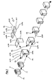
- this invention relates to a method to form a cover shaped like an inverted "U" on top of a product, including a front, an upper and a back panel, or a cover that includes the aforementioned three panels and furthermore some closing flaps, in order to form a quadrangular cover with an upper panel and four perimetrical edges joined together.
- these methods are arduous and slow if used to form two-piece packages, as for example packages including the above said cover and a tray around the base of the product; in which said two pieces, if desired, can easily be joined together and separated, with the purpose of transporting the product within a closed package and with the purpose of making the product visible through an easy and rapid removal of the top cover.
- the products P are translated from upstream to downstream along a first path P1 of products translation, for example driven by a translation force F1 acting directly on product P.
- the set obtained by P+A and placed downstream of the zone Z1 will comprise a product P partially covered by a blank-cover A correctly placed and centered, namely with the upper panel A-PS lying correctly on top of the upper side of the product P and with the front panel A-PA correctly placed against the front side of the product P.
- first force F1 directly on the product P
- second force F2 directly on the blank-cover A; in which said second force F2 will preferably be applied at first along the back edge of the back panel A-PP during the second operation b) and, after and/or during the folding towards the bottom of said back panel A-PP, i.e. third operation c) , along the back edge of the upper panel A-PS.
- this second path P2 can also include a second segment upstream aligned, along which the blank-cover A would be folded from its original flat configuration to its folded configuration.
- a continuous flow of product P is translated, preferably in a continuous motion, in a single succession and spaced to eachother along the first path P1 and, at the same time, a blank-cover A in a folded configuration can be inserted and placed in said zone Z1 in phase correlation and in a single succession, using for this insertion/positioning operation the time interval between two products P positioned in an immediate succession.
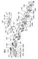
- Figure 1A illustrates a second form of realization of the aforementioned basic method here used to form a quadrangular cover with lateral edges on top of the product P.
- the blank-cover here indicated as A1
- A1 besides the aforementioned front, upper and back panels, A-PA, A-PS, A-PP, also includes closing flaps determined by means of creases and, more particularly, front closing flaps A-PAsx and A-PAdx placed on the opposite transversal ends of the front panel A-PA, upper closing flaps, A-PSsx, A-PSdx, placed on the opposite transversal ends of the upper panel A-PS, and back closing flaps, A-PPsx, A-PPdx, placed on the opposite transversal ends of the back panel A-PP.
- closing flaps determined by means of creases and, more particularly, front closing flaps A-PAsx and A-PAdx placed on the opposite transversal ends of the front panel A-PA, upper closing flaps, A-PSsx, A-PSdx, placed on the opposite transversal ends of the upper panel A-PS, and back closing flaps, A-PPsx, A-PPdx, placed on
- the closing flaps A-PSsx and A-PSdx of the upper panel A-PS with and above the closing flaps A-PAsx, A-PAdx, A-PPsx, A-PPdx, of the front panel A-PA and of the back panel A-PP; in which in order to obtain said joints adhesive is placed on the internal-lower side of the upper closing flaps, A-PSsx and A-PSdx, of the upper panel A-PS and/or on the external side of the front closing flaps, A-PAsx and A-PAdx, of the front panel A-PA, and/or on the external side of the back closing flaps, A-PPsx and A-PPdx, of the back panel A-PP, in which also preferably, said adhesive is applied during the translation of the blank-cover A along the first translation path P1.
- a quadrangular cover will be formed on top of the product P, which will have an upper panel PS and four vertical edges on the four sides, in which said upper panel PS and the four vertical edges are joined together.
- said adhesive should preferably be applied during the translation of the blank cover A along the first translation path P1.
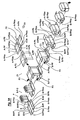
- FIG. 3 illustrates a fourth realization in which during the translating the product P along the first path P1, a tray is formed close to the base of the product P, in order to form a two-piece package with a cover shaped like an inverted "U” and a quadrangular tray with lateral edges close to the base of the product.
- the cover shaped like a "U” is formed by means of the blank-cover A from the first realization and following the same operative method.
- a second blank-tray B which, with respect to a longitudinal extension axis B-Y, includes a front panel B-PA with closing flaps B-PAsx, B-PAdx, an inferior panel B-PI with closing flaps B-PIsx, B-PIdx, and a back panel B-PP with closing flaps B-PPsx, B-PPdx, all of these separated by means of creases.
- this fourth realization comprises the following operations: a) -the aforementioned blank-tray B is placed flat along the first translation path P1 of products P translation, with the inferior panel B-PI placed under the bottom side of the product P, the front panel B-PA placed downstream, and the back panel B-PP placed upstream; b) -in the first zone Z1, upstream from the first path P1, a blank-cover A is placed in a folded configuration above and in front of the product P, with its back A-PP and upper A-PS panels horizontally coplanar placed above the upper side of the product P and with the front panel A-PA vertically placed in front of the front side of the product P; c) -the blank-cover A is translated in this aforementioned folded configuration from the first zone, Z1, downstream along the first path P1, as soon as the front side of the product P comes near or against the front panel A-PA of the blank-cover A; d)-the back panel A-PP of the blank-cover A is folded against the back
- FIG. 3A it illustrates a fifth realization during which while translating the product P along the first path P1, a quadrangular cover with lateral edges is formed on top of the product P and a quadrangular tray with lateral edges is formed around the base of said product.
- the cover is formed by means of the blank-cover A1 from the second realization and by using the basic method from the first realization, while the bottom tray is formed by using a blank-tray B like in the previous fourth realization.
- said fifth realization comprises the following operations: a) -the aforementioned blank-tray B is placed flat along the first translation path P1 of products P translation, with the lower panel B-PI placed under the bottom side of the product P, the front panel B-PA placed downstream, and the back panel B-PP placed upstream; b) -in the first zone Z1, upstream from the first path P1, a blank-cover A is placed in a folded configuration above and in front of the product P, with its back A-PP and upper A-PS panels horizontally coplanar placed above the upper side of the product P and with the front panel A-PA vertically placed in front of the front side of the product P; c)-the blank-cover A is translated in the aforementioned folded configuration from the first zone, Z1, downstream along the first path P1, as soon as the front side of the product P placed over the inferior panel B-PI of the blank-tray B comes near or against the front panel A-PA of the blank-cover A; d) -the back panel A-PP of the
- the front panel A-PA it is preferable for the front panel A-PA to be joined to the front panel B-PA, by applying the adhesive C1, C2, on the external side of the front panel A-PA and/or on the internal side of the front panel B-PA, in those zones where these two sides will be joined together and where the adhesive will preferably be applied on during the translation of the blanks along said first P1 or second P2 translation paths.
Landscapes
- Engineering & Computer Science (AREA)
- Mechanical Engineering (AREA)
- Making Paper Articles (AREA)
- Closing Of Containers (AREA)
Claims (37)
- Verfahren zum Bilden eines Deckels auf einem Produkt (P), wobei der Deckel aus einem Deckelzuschnitt (A/A1) gebildet wird, der bezüglich einer Längsachse (A-Y) wenigstens ein hinteres Feld (A-PP), ein oberes Feld (A-PS) und ein vorderes Feld (A-PA) umfasst, die durch quer verlaufende Knicklinien (A-10, A-20) voneinander getrennt sind, und wobei das Produkt (P) auf einer ersten Produktvorschubbahn (P1) in Arbeitsrichtung nach vom bewegt wird, gekennzeichnet durch die folgenden Arbeitsschritte:a) in einer ersten Zone (Z1) der ersten Vorschubbahn (P1) wird ein Deckelzuschnitt (A/A1) in gefalzter Form so über und vor das Produkt (P) gelegt, dass das hintere Feld (A-PP) und das obere Feld (A-PS) horizontal komplanar über der Oberseite des Produktes (P) und das vordere Feld (A-PA) vertikal vor dem Produkt (P) liegen,b) der Deckelzuschnitt (A/A1) wird in der gefalzten Form entlang der ersten Vorschubbahn (P1) aus der ersten Zone (Z1) nach vom bewegt, sobald oder kurz bevor die Vorderseite des Produkts (P) gegen das vordere Feld (A-PA) des Zuschnitts (A) stößt,- wobei während des Arbeitsschrittes (b) eine erste Kraft (F1) unmittelbar auf das Produkt (P) wirkt und dieses dabei nach vom schiebt, während eine zweite, unterschiedliche Kraft (F2) unmittelbar auf den Deckelzuschnitt (A/A1) wirkt und diesen dabei nach vom bewegt.
- Verfahren nach Anspruch 1, dadurch gekennzeichnet, dass nach dem Arbeitsschritt (b) ein weiterer Arbeitsschritt (c) durchgeführt wird, bei dem das hintere Feld (A-PP) des Deckelzuschnitts (A/A1) gegen die Rückseite des Produktes (P) gefalzt wird, während das Produkt (P) und der Deckelzuschnitt (A/A1) auf der ersten Vorschubbahn (P1) nach vom bewegt werden.
- Verfahren nach Anspruch 1 oder 2, dadurch gekennzeichnet, dass der Deckelzuschnitt (A/A1) mit einer Lineargeschwindigkeit bewegt wird, die im wesentlichen gleich der linearen Vorschubgeschwindigkeit des Produktes (P) ist.
- Verfahren nach Anspruch 2 oder 3, dadurch gekennzeichnet, dass während der Durchführung des Arbeitsschrittes (c) eine erste Kraft (F1) unmittelbar auf das Produkt (P) ausgeübt wird, um dieses nach vom zu schieben, während eine davon abweichende zweite Kraft (F2) unmittelbar auf den Deckelzuschnitt (A/A1) wirkt, um diesen nach unten zu falten und nach vom zu schieben.
- Verfahren nach einem der Ansprüche 1 bis 4, dadurch gekennzeichnet, dass zur Durchführung des Arbeitsschrittes (a) der Deckelzuschnitt (A/A1) in gefalzter Form auf einer zweiten Vorschubbahn (P2) für diesen Zuschnitt (A/A1) vorgeschoben wird.
- Verfahren nach Anspruch 5, dadurch gekennzeichnet, dass die zweite Vorschubbahn (P2) für den Deckelzuschnitt (A/A1) schräg oder quer zu der ersten Vorschubbahn (P1) verläuft.
- Verfahren nach einem der Ansprüche 1 bis 6, dadurch gekennzeichnet, dass zur Durchführung des Arbeitsschrittes (a) der Deckelzuschnitt (A/A1) in gefalzter Form auf der zweiten Vorschubbahn (P2) vorgeschoben wird, wobei das obere Feld (A-PS) und das hintere Feld (A-PP) über das Produkt (P) gelegt werden.
- Verfahren nach einem der Ansprüche 1 bis 7, dadurch gekennzeichnet, dass vor dem Arbeitsschritt (a) der Deckelzuschnitt (A/A1) aus seiner flachen Form in eine gefaltete Form gefalzt wird.
- Verfahren nach Anspruch 8, dadurch gekennzeichnet, dass vor dem Arbeitsschritt (a) der Deckelzuschnitt (A/A1) auf einem Abschnitt der zweiten Vorschubbahn (P2) für den Deckelzuschnitt (A/A1) aus seiner flachen Form in die gefaltete Form gefalzt wird.
- Verfahren nach einem der vorhergehenden Ansprüche, dadurch gekennzeichnet, dass auf der ersten Vorschubbahn (P1) die Produkte (P) mit Abstand voneinander und mit kontinuierlicher Bewegung vorgeschoben werden und dass in der ersten Zone (Z1) die Deckelzuschnitte (A/A1) einzeln nacheinander eingeschoben werden, wozu die Abstände zwischen den aufeinander folgenden Produkten (P) genutzt werden.
- Verfahren nach einem der vorhergehenden Ansprüche, dadurch gekennzeichnet, dass der Deckelzuschnitt (A/A1) weiterhin aufweist:- vordere Verschlusslaschen (A-PAsx, A-PAdx) an den gegenüberliegenden Querenden des vorderen Feldes (A-PA),- obere Verschlusslaschen (A-PSsx, A-PSdx) an den gegenüberliegenden Querenden des oberen Feldes (A-PS),- hintere Verschlusslaschen (A-PPsx, A-PPdx) an den gegenüberliegenden Querenden des hinteren Feldes (A-PP),
und dass nach dem Arbeitsschritt (b) die folgenden Arbeitsschritte durchgeführt werden:c1) die Verschlusslaschen (A-PAsx, A-PAdx) des vorderen Feldes (A-PA) des Zuschnitts (A1) werden gegen das Produkt (P) nach innen geknickt,c2) die Verschlusslaschen (A-PPsx, A-PPdx) des hinteres Feldes (A-PP) des Zuschnitts (A1) werden nach unten gefalzt,c3) das hintere Feld (A-PP) des Zuschnitts (A1) wird gegen das Produkt (P) nach unten geknickt,c4) die Verschlusslaschen (A-PSsx, A-PSdx) des oberen Feldes (A-PS) des Zuschnitts (A1) werden gegen die Verschlusslaschen (A-PAsx, A-PPsx, A-PAdx, A-PPdx) des vorderen Feldes (A-PA) und des hinteren Feldes (A-PP) nach unten geknickt. - Verfahren nach Anspruch 11, dadurch gekennzeichnet, dass die Verschlusslaschen (A-PSsx, A-PSdx) des oberen Feldes (A-PS) des Zuschnitts (A1) mit dem und über die Verschlusslaschen (A-PAsx, A-PAdx, A-PPsx, A-PPdx) des vorderen Feldes (A-PA) und des hinteren Feldes (A-PP) des Zuschnitts (A1) mit diesen verbunden werden.
- Verfahren nach Anspruch 12, dadurch gekennzeichnet, dass für die gegenseitige Verbindung auf die Innenseite der Verschlusslaschen (A-PSsx, A-PSdx) des oberen Feldes (A-PS) des Zuschnitts (A1) ein Klebstoff aufgetragen wird.
- Verfahren nach Anspruch 12 oder 13, dadurch gekennzeichnet, dass für die gegenseitige Verbindung auf die Außenseite der Verschlusslaschen (A-PAsx, A-PAdx) des vorderen Feldes (A-PA) des Zuschnitts (A1) ein Klebstoff aufgetragen wird.
- Verfahren nach einem der Ansprüche 12 bis 14, dadurch gekennzeichnet, dass für die gegenseitige Verbindung auf die Außenseite der Verschlusslaschen (A-PPsx, A-PPdx) des hinteren Feldes (A-PP) des Zuschnitts (A1) ein Klebstoff aufgetragen wird.
- Verfahren nach einem der Ansprüche 13 bis 15, dadurch gekennzeichnet, dass der Klebstoff während des Vorschubs des Zuschnitts (A1) auf der ersten Vorschubbahn (P1) aufgetragen wird.
- Verfahren nach einem der Ansprüche 1 bis 10, dadurch gekennzeichnet, dass der Deckelzuschnitt (A/A1) weiterhin aufweist:- vordere Verschlusslaschen (A-PAsx, A-PAdx) an den gegenüberliegenden Querenden des vorderen Feldes (A-PA),- obere Verschlusslaschen (A-PSsx, A-PSdx) an den gegenüberliegenden Querenden des oberen Feldes (A-PS),- hintere Verschlusslaschen (A-PPsx, A-PPdx) an den gegenüberliegenden Querenden des hinteren Feldes (A-PP),
und dass nach dem Arbeitsschritt (b) die folgenden Arbeitsschritte durchgeführt werden:c1) die Verschlusslaschen (A-PSsx, A-PSdx) des oberen Feldes (A-PS) des Zuschnitts (A1) werden gegen das Produkt (P) nach unten geknickt,c2) die Verschlusslaschen (A-PPsx, A-PPdx) des hinteres Feldes (A-PP) des Zuschnitts (A1) werden nach unten gefalzt,c3) das hintere Feld (A-PP) des Zuschnitts (A1) wird gegen das Produkt (P) nach unten geknickt, wobei die Verschlusslaschen (A-PPsx, A-PPdx) des hinteren Feldes (A-PP) über die Verschlusslaschen (A-PSsx, A-PSdx) des oberen Feldes (A-PS) geknickt werden,c4) die Verschlusslaschen (A-PAsx, A-PAdx) des vorderen Feldes (A-PA) des Zuschnitts (A1) werden über die Verschlusslaschen (A-PSsx, A-PSdx) des oberen Feldes (A-PS) nach innen geknickt. - Verfahren nach Anspruch 17, dadurch gekennzeichnet, dass die Verschlusslaschen (A-PAsx, A-PAdx, A-PPsx, A-PPdx) des vorderen Feldes (A-PA) und des hinteren Feldes (A-PP) des Zuschnitts (A1) werden über die Verschlusslaschen (A-PSsx, A-PSdx) des oberen Feldes (A-PS) des Zuschnitts (A1) mit diesen verbunden.
- Verfahren nach Anspruch 18, dadurch gekennzeichnet, dass für die gegenseitige Verbindung auf die Außenseite der Verschlusslaschen (A-PSsx, A-PSdx) des oberen Feldes (A-PS) des Zuschnitts (A1) ein Klebstoff aufgetragen wird.
- Verfahren nach Anspruch 18 oder 19, dadurch gekennzeichnet, dass für die gegenseitige Verbindung auf die Innenseite der Verschlusslaschen (A-PAsx, A-PAdx) des vorderen Feldes (A-PA) des Zuschnitts (A1) ein Klebstoff aufgetragen wird.
- Verfahren nach einem der Ansprüche 18 bis 20, dadurch gekennzeichnet, dass für die gegenseitige Verbindung auf die Innenseite der Verschlusslaschen (A-PPsx, A-PPdx) des hinteren Feldes (A-PP) des Zuschnitts (A1) ein Klebstoff aufgetragen wird.
- Verfahren nach einem der Ansprüche 19 bis 21, dadurch gekennzeichnet, dass der Klebstoff während des Vorschubs des Zuschnitts (A1) auf der ersten Vorschubbahn (P1) augetragen wird.
- Verfahren nach einem der vorhergehenden Ansprüche, dadurch gekennzeichnet, dass auf der ersten Vorschubbahn (P1) weitere Arbeitsschritte durchgeführt werden, um einen Schachtelzuschnitt (B) unter den Boden des Produkts (P) einzusetzen und um diesen zweiten Zuschnitt (B) um die Basis des Produkts (P) zu falten, wodurch eine zweiteilige Verpackung mit einem nach einem der vorhergehenden Ansprüche hergestellten Deckel und mit einer Schachtel gebildet wird.
- Verfahren nach Anspruch 23, dadurch gekennzeichnet, dass der Schachtelzuschnitt (B) bezüglich einer Längsachse (B-Y) wenigtens ein vorderes Feld (B-PA), ein unteres Feld (B-PI) und ein hinteres Feld (B-PP) umfasst, die durch Knicklinien voneinander getrennt sind, und dass der Schachtelzuschnitt (B) in flacher Form auf die erste Vorschubbahn (P1) der Produkte (P) gelegt wird, wobei das untere Feld (B-PI) so unter dem Boden des Produktes (P) liegt, dass das vordere Feld (B-PA) in Arbeitsrichtung nach vom und das hintere Feld (B-PP) nach hinten weisen.
- Verfahren nach einem der vorhergehenden Ansprüche, dadurch gekennzeichnet, dass während des Vorschubs des Produktes (P) auf der ersten Vorschubbahn (P1) eine zweiteilige Verpackung gebildet wird, die aus einem Deckel in Form eines auf dem Produkt (P) kopfstehenden U und einer viereckigen Schachtel mit unmittelbar neben dem Produkt liegenden Seitenkanten besteht, wobei der Deckel aus einem Deckelzuschnitt (A) gebildet wird, der bezüglich der Längsachse (A-Y) wenigstens ein hinteres Feld (A-PP), ein oberes Feld (A-PS) und ein vorderes Feld (A-PA) umfasst, die durch Knicklinien voneinander getrennt sind, während die Schachtel aus dem Schachtelzuschnitt (B) gebildet wird, der bezüglich der Längsachse (B-Y) wenigstens ein vorderes Feld (B-PA) mit Verschlusslaschen (B-PAsx, B-PAdx), ein unteres Feld (B-PI) mit Verschlusslaschen (B-PIsx, B-PIdx) sowie ein hinteres Feld (B-PP) mit Verschlusslaschen (B-PPsx, B-PPdx) umfasst, die durch Knicklinien voneinander getrennt sind, und dadurch gekennzeichnet, dass das Verfahren die folgenden Arbeitsschritte aufweist:a) der Schachtelzuschnitt (B) wird in flacher Form auf die erste Vorschubbahn (P1) der Produkte (P) gelegt, wobei das untere Feld (B-PI) so unter dem Boden des Produktes (P) liegt, dass das vordere Feld (B-PA) in Arbeitsrichtung nach vom und das hintere Feld (B-PP) nach hinten weisen,b) in der ersten Zone (Z1) am Beginn der Vorschubbahn (P1) wird der Deckelzuschnitt (A) in gefalzter Form so über und vor das Produkt (P) gelegt, dass das hintere Feld (A-PP) und das obere Feld (A-PS) horizontal und komplanar zueinander über der Oberseite des Produktes (P) und das vordere Feld (A-PA) vertikal vor dem Produkt (P) liegen,c) der Deckelzuschnitt (A) wird in dieser gefalzten Form entlang der ersten Vorschubbahn (P1) aus der ersten Zone (Z1) nach vom bewegt, sobald die Vorderseite des auf dem unteren Feld (B-PI) des Schachtelzuschnitts (B) stehenden Produkts (P) gegen das vordere Feld (A-PA) des Zuschnitts (A) stößt oder in dessen Nähe kommt,d) das hintere Feld (A-PP) des Deckelzuschnitts (A) wird gegen die Rückseite des Produkts (P) gefalzt, während der Schachtelzuschnitt (B) zusammen mit dem Produkt (P) und dem Deckelzuschnitt (A) auf der ersten Vorschubbahn (P1) weiterbewegt werden,e) es werden die Arbeitsschritte durchgeführt, um das vordere Feld (B-PA), das hintere Feld (B-PP) und die Verschlusslaschen (B-PAsx, B-PAdx, B-PIsx, B-PIdx, B-PPsx und B-PPdx) des Schachtelzuschnitts (B) um die Basis des Produkts (P) zu falzen.
- Verfahren nach Anspruch 25, dadurch gekennzeichnet, dass nach dem Arbeitsschritt (d) die folgenden Arbeitsschritte durchgeführt werden:e1) das vordere Feld (B-PA) des Schachtelzuschnitts (B) wird gegen das vordere Feld (A-PA) des Deckelzuschnitts (A) gefalzt,e2) die Verschlusslaschen (B-PPsx, B-PPdx) des hinteren Feldes (B-PP) des Schachtelzuschnitts (B) werden nach oben geknickt,e3) die Verschlusslaschen (B-PAsx, B-PAdx) des vorderen Felds (B-PA) des Schachtelzuschnitts (B) werden nach innen und gegen das Produkt (P) geknickt,e4) das hintere Feld (B-PP) des Schachtelzuschnitts (B) wird gegen das hintere Feld (A-PP) des Deckelzuschnitts (A) geknickt, wobei die Verschlusslaschen (B-PPsx, B-PPdx) des hinteren Feldes (B-PP) des Schachtelzuschnitts (B) neben den Seitenflächen des Produktes (P) zu liegen kommen,e5) die Verschlusslaschen (B-PIsx, B-PIdx) des unteren Feldes (B-PI) des Schachtelzuschnitts (B) werden nach oben gegen die Verschlusslaschen (B-PAsx, B-PPsx, B-PAdx, B-PPdx) des vorderen Feldes (B-PA) und des hinteren Feldes (B-PP) des Schachtelzuschnitts (B) gefalzt.
- Verfahren nach einem der Ansprüche 1 bis 24, dadurch gekennzeichnet, dass während des Vorschubs des Produktes (P) auf der ersten Vorschubbahn (P1) eine zweiteilige Verpackung gebildet wird, die aus einem auf dem Produkt (P) liegenden, viereckigen Deckel mit Seitenkanten und einer viereckigen Schachtel mit unmittelbar neben der Basis des Produktes (P) liegenden Seitenkanten besteht, wobei der Deckel aus einem ersten Deckelzuschnitt (A1) gebildet wird, der bezüglich der Längsachse (A-Y) und durch Knicklinien voneinander getrennt wenigstens ein vorderes Feld (A-PA) mit Verschlusslaschen (A-PAsx, A-PAdx), ein oberes Feld (A-PS) mit Verschlusslaschen (A-PSsx, A-PSdx) und ein hinteres Feld (A-PP) mit Verschlusslaschen (A-PPsx, A-PPdx) umfasst, wobei die Schachtel aus einem zweiten Schachtelzuschnitt (B) gebildet wird, der bezüglich der Längsachse (B-Y) und durch Knicklinien voneinander getrennt wenigstens ein vorderes Feld (B-PA) mit Verschlusslaschen (B-PAsx, B-PAdx), ein unteres Feld (B-PI) mit Verschlusslaschen (B-PIsx, B-PIdx) sowie ein hinteres Feld (B-PP) mit Verschlusslaschen (B-PPsx, B-PPdx) umfasst, und dadurch gekennzeichnet, dass das Verfahren die folgenden Arbeitsschritte aufweist:a) der Schachtelzuschnitt (B) wird in flacher Form auf die erste Vorschubbahn (P1) der Produkte (P) gelegt, wobei das untere Feld (B-PI) so unter dem Boden des Produktes (P) liegt, dass das vordere Feld (B-PA) in Arbeitsrichtung nach vom und das hintere Feld (B-PP) nach hinten weisen,b) in der ersten Zone (Z1) am Beginn der Vorschubbahn (P1) wird der Deckelzuschnitt (A) in gefalzter Form so über und vor das Produkt (P) gelegt, dass das hintere Feld (A-PP) und das obere Feld (A-PS) horizontal und komplanar zueinander über der Oberseite des Produktes (P) und das vordere Feld (A-PA) vertikal vor dem Produkt (P) liegen,c) der Deckelzuschnitt (A) wird in dieser gefalzten Form entlang der ersten Vorschubbahn (P1) aus der ersten Zone (Z1) nach vom bewegt, sobald die Vorderseite des auf dem unteren Feld (B-PI) des Schachtelzuschnitts (B) stehenden Produkts (P) gegen das vordere Feld (A-PA) des Zuschnitts (A) stößt oder in dessen Nähe kommt,d) das hintere Feld (A-PP) des Deckelzuschnitts (A) wird gegen die Rückseite des Produkts (P) gefalzt, während der Schachtelzuschnitt (B) zusammen mit dem Produkt (P) und dem Deckelzuschnitt (A) auf der ersten Vorschubbahn (P1) weiterbewegt werden,e) es werden die Arbeitsschritte durchgeführt, um die übrigen Felder und die Verschlusslaschen zu falzen, wodurch die Bildung des viereckigen Deckels mit den seitlichen Kanten und der viereckigen Schachtel mit den seitlichen Kanten vervollständigt wird.
- Verfahren nach Anspruch 27, dadurch gekennzeichnet, dass nach dem Arbeitsschritt (d) die folgenden Arbeitsschritte durchgeführt werden:e1) die Verschlusslaschen (A-PAsx, A-PAdx) des vorderen Feldes (A-PA) des Deckelzuschnitts (A1) werden gegen das Produkt (P) gefalzt,e2) die Verschlusslaschen (A-PPsx, A-PPdx) des hinteren Feldes (A-PP) des Deckelzuschnitts (A1) werden nach unten geknickt,e3) das vordere Feld (B-PA) des Schachtelzuschnitts (B) wird gegen das vordere Feld (A-PA) des Deckelzuschnitts (A) gefalzt,e4) das hintere Feld (A-PP) des Deckelzuschnitts (A1) wird so gegen das Produkt (P) nach unten gefalzt, dass die Verschlusslaschen (A-PPsx, A-PPdx) des hinteren Feldes (A-PP) auf den Seiten des Produktes (P) liegen,e5) die Verschlusslaschen (B-PPsx, B-PPdx) des hinteren Feldes (B-PP) des Schachtelzuschnitts (B) werden nach oben geknickt,e6) die Verschlusslaschen (B-PAsx, B-PAdx) des vorderen Feldes (B-PA) des Schachtelzuschnitts (B) werden gegen die entsprechenden Verschlusslaschen (A-PAsx, A-PAdx) des vorderen Feldes (A-PA) des Deckelzuschnitts (A1) gefalzt,e7) das hintere Feld (B-PP) des Schachtelzuschnitts (B) wird so gegen das hintere Feld (A-PP) des Deckelzuschnitts (A1) gefalzt, dass die Verschlusslaschen (B-PPsx, B-PPdx) des hinteren Feldes (B-PP) des Schachtelzuschnitts (B) neben den Verschlusslaschen (A-PPsx, A-PPdx) des hinteren Feldes (A-PP) des Deckelzuschnitts (A1) liegen,e8) die Verschlusslaschen (A-PSsx, A-PSdx) des oberen Feldes (A-PS) des Deckelzuschnitts (A) werden gegen die Verschlusslaschen (A-PAsx, A-PPsx, A-PAdx, A-PPdx) des vorderen (A-PA) und des hinteren Feldes (A-PP) nach unten gefalzt,e9) die Verschlusslaschen (B-PIsx, B-PIdx) des unteren Feldes (B-PI) des Schachtelzuschnitts (B) werden gegen die Verschlusslaschen (B-PAsx, B-PPsx, B-PAdx, B-PPdx) des vorderen (B-PA) und des hinteren Feldes (B-PP) des Schachtelzuschnitts (B) nach oben gefalzt.
- Verfahren nach einem der Ansprüche 25 bis 28, dadurch gekennzeichnet, dass der Deckel mit der Schachtel verbunden wird.
- Verfahren nach Anspruch 29, dadurch gekennzeichnet, dass die Verbindung einen kalibrierten Widerstand hat, der ein leichtes Öffnen ermöglicht.
- Verfahren nach einem der Ansprüche 25 bis 30, dadurch gekennzeichnet, dass das vordere Feld (A-PA) des Deckelzuschnitts (A) und das vordere Feld (B-PA) des Schachtelzuschnitts (B) miteinander verbunden werden.
- Verfahren nach Anspruch 31, dadurch gekennzeichnet, dass für die Verbindung ein Klebstoff (C2) verwendet wird, der auf die Außenseite des vorderen Feldes (A-PA) des Deckelzuschnitts (A) und/oder ein Klebstoff (C1) verwendet wird, der auf die Innenseite des vorderen Feldes (B-PA) des Schachtelzuschnitts (B) aufgetragen wird.
- Verfahren nach einem der Ansprüche 25 bis 32, dadurch gekennzeichnet, dass das hintere Feld (A-PP) des Deckelzuschnitts (A) und das hintere Feld (B-PP) des Schachtelzuschnitts (B) miteinander verbunden werden.
- Verfahren nach Anspruch 33, dadurch gekennzeichnet, dass für die Verbindung ein Klebstoff (C3) verwendet wird, der auf die Außenseite des hinteren Feldes (A-PP) des Deckelzuschnitts (A) und/oder ein Klebstoff (C4) verwendet wird, der auf die Innenseite des hinteren Feldes (B-PP) des Schachtelzuschnitts (B) aufgetragen wird.
- Verfahren nach einem der Ansprüche 32 bis 34, dadurch gekennzeichnet, dass der Klebstoff während des Vorschubs des Deckelzuschnitts (A/A1) und des Schachtelzuschnitts (B) auf der ersten Vorschubbahn (P1) aufgetragen wird.
- Deckel, hergestellt mit einem Verfahren nach einem der vorhergehenden Ansprüche.
- Zweiteilige Verpackung mit einem Deckel und einer Schachtel, hergestellt nach einem der Ansprüche 25 bis 35.
Applications Claiming Priority (1)
| Application Number | Priority Date | Filing Date | Title |
|---|---|---|---|
| ITBO20070132 ITBO20070132A1 (it) | 2007-02-28 | 2007-02-28 | Metodo per formare un coperchio sulla sommita di un prodotto e/o un imballo in due pezzi comprendente detto coperchio ed un vassoio |
Publications (3)
| Publication Number | Publication Date |
|---|---|
| EP1982918A2 EP1982918A2 (de) | 2008-10-22 |
| EP1982918A3 EP1982918A3 (de) | 2012-07-04 |
| EP1982918B1 true EP1982918B1 (de) | 2013-11-20 |
Family
ID=39720671
Family Applications (1)
| Application Number | Title | Priority Date | Filing Date |
|---|---|---|---|
| EP08101874.9A Not-in-force EP1982918B1 (de) | 2007-02-28 | 2008-02-22 | Verfahren zum Bilden eines Deckels auf einem Produkt und/oder zum Bilden einer zweiteiligen Verpackung aus dem Deckel und einem Träger |
Country Status (2)
| Country | Link |
|---|---|
| EP (1) | EP1982918B1 (de) |
| IT (1) | ITBO20070132A1 (de) |
Families Citing this family (2)
| Publication number | Priority date | Publication date | Assignee | Title |
|---|---|---|---|---|
| DE102009003740A1 (de) * | 2009-04-03 | 2010-10-07 | Meypack Verpackungssystemtechnik Gmbh | Verfahren zur Herstellung eines Verpackungskartons, und Verpackungsmaschine |
| DE102018203180A1 (de) * | 2018-03-02 | 2019-09-05 | Krones Aktiengesellschaft | Verpackungsvorrichtung für Artikel und Verfahren zum Verpacken von Artikeln |
Family Cites Families (3)
| Publication number | Priority date | Publication date | Assignee | Title |
|---|---|---|---|---|
| DE4018140C1 (de) * | 1990-06-06 | 1991-09-26 | Kisters Maschinenbau Gmbh, 4190 Kleve, De | |
| DE19712787A1 (de) * | 1997-03-26 | 1998-10-01 | Schrutt Gmbh | Vorrichtung zum Einsetzen eines Deckelzuschnittes in einen Verkaufskarton |
| IT1315198B1 (it) * | 1999-07-09 | 2003-02-03 | Zambelli Alberto | Scatola di cartone ondulato per l'imballaggio di prodotti e metodo edapparato per la realizzazione e per l'impiego su scala industriale di |
-
2007
- 2007-02-28 IT ITBO20070132 patent/ITBO20070132A1/it unknown
-
2008
- 2008-02-22 EP EP08101874.9A patent/EP1982918B1/de not_active Not-in-force
Also Published As
| Publication number | Publication date |
|---|---|
| EP1982918A2 (de) | 2008-10-22 |
| EP1982918A3 (de) | 2012-07-04 |
| ITBO20070132A1 (it) | 2008-09-01 |
Similar Documents
| Publication | Publication Date | Title |
|---|---|---|
| EP1997736A2 (de) | Verfahren zum herstellen eine zweiteilige Verpackung, die einen oberen und einen unteren Teil aufweist, und entsprechende Verpackung | |
| US11305903B2 (en) | Box template folding process and mechanisms | |
| CA2043941C (en) | Packaging system | |
| JP5869304B2 (ja) | ヒンジ式蓋付きパッケージとヒンジ式蓋付きパッケージを製造する包装方法および包装機 | |
| RU2631173C2 (ru) | Предварительно собранная открытая коробка с автоматически формируемыми опорами для штабелирования | |
| US7998049B1 (en) | Cartoner for cartons having concave sides | |
| CN108883845A (zh) | 用于使具有倾斜山形墙的包装件的山形墙表面成形的设备和方法 | |
| US20080081754A1 (en) | Container forming machines and methods | |
| CN103582600A (zh) | 用于包装物品的纸盒和制造它的坯料及方法 | |
| EP1982918B1 (de) | Verfahren zum Bilden eines Deckels auf einem Produkt und/oder zum Bilden einer zweiteiligen Verpackung aus dem Deckel und einem Träger | |
| US2701938A (en) | Method and apparatus for packaging cans and bottles in carrier cartons | |
| WO2018002791A1 (en) | Package for containing and displaying precious and luxury products or items, such as perfumes, creams, alcoholic products, high-end cosmetics, high fashion accessories, jewelry and/or the like | |
| CN108473245A (zh) | 零售展示盒 | |
| WO2025132411A1 (en) | Process and machine for packaging, and related packaging | |
| AU2012345486B2 (en) | Method of and apparatus for erecting containers | |
| US7024838B2 (en) | Packaging apparatus | |
| EP1954566B1 (de) | Maschine zum anheben von planaren artikeln | |
| US3760555A (en) | Packaging machine | |
| EP1531032B1 (de) | Montagevorrichtung und Montageverfahren für Holzkisten | |
| US2057782A (en) | Apparatus for stapling containers | |
| GB2229710A (en) | Packages formed from blanks | |
| GB2473963A (en) | Packaging tray | |
| ITBO20080512A1 (it) | Apparecchiatura di confezionamento. | |
| GB2554124A (en) | Package for containing and displaying precious and luxury products or items, such as perfumes, creams, alcoholic products, high-end cosmetics, | |
| GB2495478A (en) | Conveying and collapsing crates |
Legal Events
| Date | Code | Title | Description |
|---|---|---|---|
| PUAI | Public reference made under article 153(3) epc to a published international application that has entered the european phase |
Free format text: ORIGINAL CODE: 0009012 |
|
| AK | Designated contracting states |
Kind code of ref document: A2 Designated state(s): AT BE BG CH CY CZ DE DK EE ES FI FR GB GR HR HU IE IS IT LI LT LU LV MC MT NL NO PL PT RO SE SI SK TR |
|
| AX | Request for extension of the european patent |
Extension state: AL BA MK RS |
|
| PUAL | Search report despatched |
Free format text: ORIGINAL CODE: 0009013 |
|
| RIC1 | Information provided on ipc code assigned before grant |
Ipc: B65B 5/02 20060101AFI20120515BHEP Ipc: B65B 21/24 20060101ALI20120515BHEP |
|
| AK | Designated contracting states |
Kind code of ref document: A3 Designated state(s): AT BE BG CH CY CZ DE DK EE ES FI FR GB GR HR HU IE IS IT LI LT LU LV MC MT NL NO PL PT RO SE SI SK TR |
|
| AX | Request for extension of the european patent |
Extension state: AL BA MK RS |
|
| RIC1 | Information provided on ipc code assigned before grant |
Ipc: B65B 21/24 20060101ALI20120531BHEP Ipc: B65B 5/02 20060101AFI20120531BHEP |
|
| 17P | Request for examination filed |
Effective date: 20121220 |
|
| AKX | Designation fees paid |
Designated state(s): AT BE BG CH CY CZ DE DK EE ES FI FR GB GR HR HU IE IS IT LI LT LU LV MC MT NL NO PL PT RO SE SI SK TR |
|
| GRAP | Despatch of communication of intention to grant a patent |
Free format text: ORIGINAL CODE: EPIDOSNIGR1 |
|
| RIN1 | Information on inventor provided before grant (corrected) |
Inventor name: GAMBETTI, CRISTINA |
|
| GRAP | Despatch of communication of intention to grant a patent |
Free format text: ORIGINAL CODE: EPIDOSNIGR1 |
|
| INTG | Intention to grant announced |
Effective date: 20130612 |
|
| GRAS | Grant fee paid |
Free format text: ORIGINAL CODE: EPIDOSNIGR3 |
|
| GRAA | (expected) grant |
Free format text: ORIGINAL CODE: 0009210 |
|
| AK | Designated contracting states |
Kind code of ref document: B1 Designated state(s): AT BE BG CH CY CZ DE DK EE ES FI FR GB GR HR HU IE IS IT LI LT LU LV MC MT NL NO PL PT RO SE SI SK TR |
|
| REG | Reference to a national code |
Ref country code: GB Ref legal event code: FG4D |
|
| REG | Reference to a national code |
Ref country code: CH Ref legal event code: EP |
|
| REG | Reference to a national code |
Ref country code: AT Ref legal event code: REF Ref document number: 641440 Country of ref document: AT Kind code of ref document: T Effective date: 20131215 |
|
| REG | Reference to a national code |
Ref country code: IE Ref legal event code: FG4D |
|
| REG | Reference to a national code |
Ref country code: DE Ref legal event code: R096 Ref document number: 602008028789 Country of ref document: DE Effective date: 20140116 |
|
| REG | Reference to a national code |
Ref country code: NL Ref legal event code: VDEP Effective date: 20131120 |
|
| REG | Reference to a national code |
Ref country code: AT Ref legal event code: MK05 Ref document number: 641440 Country of ref document: AT Kind code of ref document: T Effective date: 20131120 |
|
| REG | Reference to a national code |
Ref country code: LT Ref legal event code: MG4D |
|
| PG25 | Lapsed in a contracting state [announced via postgrant information from national office to epo] |
Ref country code: FI Free format text: LAPSE BECAUSE OF FAILURE TO SUBMIT A TRANSLATION OF THE DESCRIPTION OR TO PAY THE FEE WITHIN THE PRESCRIBED TIME-LIMIT Effective date: 20131120 Ref country code: SE Free format text: LAPSE BECAUSE OF FAILURE TO SUBMIT A TRANSLATION OF THE DESCRIPTION OR TO PAY THE FEE WITHIN THE PRESCRIBED TIME-LIMIT Effective date: 20131120 Ref country code: LT Free format text: LAPSE BECAUSE OF FAILURE TO SUBMIT A TRANSLATION OF THE DESCRIPTION OR TO PAY THE FEE WITHIN THE PRESCRIBED TIME-LIMIT Effective date: 20131120 Ref country code: NO Free format text: LAPSE BECAUSE OF FAILURE TO SUBMIT A TRANSLATION OF THE DESCRIPTION OR TO PAY THE FEE WITHIN THE PRESCRIBED TIME-LIMIT Effective date: 20140220 Ref country code: NL Free format text: LAPSE BECAUSE OF FAILURE TO SUBMIT A TRANSLATION OF THE DESCRIPTION OR TO PAY THE FEE WITHIN THE PRESCRIBED TIME-LIMIT Effective date: 20131120 Ref country code: HR Free format text: LAPSE BECAUSE OF FAILURE TO SUBMIT A TRANSLATION OF THE DESCRIPTION OR TO PAY THE FEE WITHIN THE PRESCRIBED TIME-LIMIT Effective date: 20131120 Ref country code: IS Free format text: LAPSE BECAUSE OF FAILURE TO SUBMIT A TRANSLATION OF THE DESCRIPTION OR TO PAY THE FEE WITHIN THE PRESCRIBED TIME-LIMIT Effective date: 20140320 |
|
| PG25 | Lapsed in a contracting state [announced via postgrant information from national office to epo] |
Ref country code: BE Free format text: LAPSE BECAUSE OF FAILURE TO SUBMIT A TRANSLATION OF THE DESCRIPTION OR TO PAY THE FEE WITHIN THE PRESCRIBED TIME-LIMIT Effective date: 20131120 Ref country code: ES Free format text: LAPSE BECAUSE OF FAILURE TO SUBMIT A TRANSLATION OF THE DESCRIPTION OR TO PAY THE FEE WITHIN THE PRESCRIBED TIME-LIMIT Effective date: 20131120 Ref country code: LV Free format text: LAPSE BECAUSE OF FAILURE TO SUBMIT A TRANSLATION OF THE DESCRIPTION OR TO PAY THE FEE WITHIN THE PRESCRIBED TIME-LIMIT Effective date: 20131120 Ref country code: AT Free format text: LAPSE BECAUSE OF FAILURE TO SUBMIT A TRANSLATION OF THE DESCRIPTION OR TO PAY THE FEE WITHIN THE PRESCRIBED TIME-LIMIT Effective date: 20131120 |
|
| PG25 | Lapsed in a contracting state [announced via postgrant information from national office to epo] |
Ref country code: PT Free format text: LAPSE BECAUSE OF FAILURE TO SUBMIT A TRANSLATION OF THE DESCRIPTION OR TO PAY THE FEE WITHIN THE PRESCRIBED TIME-LIMIT Effective date: 20140320 |
|
| PG25 | Lapsed in a contracting state [announced via postgrant information from national office to epo] |
Ref country code: EE Free format text: LAPSE BECAUSE OF FAILURE TO SUBMIT A TRANSLATION OF THE DESCRIPTION OR TO PAY THE FEE WITHIN THE PRESCRIBED TIME-LIMIT Effective date: 20131120 |
|
| REG | Reference to a national code |
Ref country code: DE Ref legal event code: R097 Ref document number: 602008028789 Country of ref document: DE |
|
| PG25 | Lapsed in a contracting state [announced via postgrant information from national office to epo] |
Ref country code: RO Free format text: LAPSE BECAUSE OF FAILURE TO SUBMIT A TRANSLATION OF THE DESCRIPTION OR TO PAY THE FEE WITHIN THE PRESCRIBED TIME-LIMIT Effective date: 20131120 Ref country code: SK Free format text: LAPSE BECAUSE OF FAILURE TO SUBMIT A TRANSLATION OF THE DESCRIPTION OR TO PAY THE FEE WITHIN THE PRESCRIBED TIME-LIMIT Effective date: 20131120 Ref country code: CZ Free format text: LAPSE BECAUSE OF FAILURE TO SUBMIT A TRANSLATION OF THE DESCRIPTION OR TO PAY THE FEE WITHIN THE PRESCRIBED TIME-LIMIT Effective date: 20131120 Ref country code: PL Free format text: LAPSE BECAUSE OF FAILURE TO SUBMIT A TRANSLATION OF THE DESCRIPTION OR TO PAY THE FEE WITHIN THE PRESCRIBED TIME-LIMIT Effective date: 20131120 |
|
| PLBE | No opposition filed within time limit |
Free format text: ORIGINAL CODE: 0009261 |
|
| STAA | Information on the status of an ep patent application or granted ep patent |
Free format text: STATUS: NO OPPOSITION FILED WITHIN TIME LIMIT |
|
| PG25 | Lapsed in a contracting state [announced via postgrant information from national office to epo] |
Ref country code: MC Free format text: LAPSE BECAUSE OF FAILURE TO SUBMIT A TRANSLATION OF THE DESCRIPTION OR TO PAY THE FEE WITHIN THE PRESCRIBED TIME-LIMIT Effective date: 20131120 Ref country code: LU Free format text: LAPSE BECAUSE OF FAILURE TO SUBMIT A TRANSLATION OF THE DESCRIPTION OR TO PAY THE FEE WITHIN THE PRESCRIBED TIME-LIMIT Effective date: 20140222 Ref country code: DK Free format text: LAPSE BECAUSE OF FAILURE TO SUBMIT A TRANSLATION OF THE DESCRIPTION OR TO PAY THE FEE WITHIN THE PRESCRIBED TIME-LIMIT Effective date: 20131120 |
|
| REG | Reference to a national code |
Ref country code: CH Ref legal event code: PL |
|
| 26N | No opposition filed |
Effective date: 20140821 |
|
| GBPC | Gb: european patent ceased through non-payment of renewal fee |
Effective date: 20140222 |
|
| PG25 | Lapsed in a contracting state [announced via postgrant information from national office to epo] |
Ref country code: CH Free format text: LAPSE BECAUSE OF NON-PAYMENT OF DUE FEES Effective date: 20140228 Ref country code: LI Free format text: LAPSE BECAUSE OF NON-PAYMENT OF DUE FEES Effective date: 20140228 |
|
| REG | Reference to a national code |
Ref country code: FR Ref legal event code: ST Effective date: 20141031 |
|
| REG | Reference to a national code |
Ref country code: IE Ref legal event code: MM4A |
|
| REG | Reference to a national code |
Ref country code: DE Ref legal event code: R097 Ref document number: 602008028789 Country of ref document: DE Effective date: 20140821 |
|
| PG25 | Lapsed in a contracting state [announced via postgrant information from national office to epo] |
Ref country code: GB Free format text: LAPSE BECAUSE OF NON-PAYMENT OF DUE FEES Effective date: 20140222 Ref country code: FR Free format text: LAPSE BECAUSE OF NON-PAYMENT OF DUE FEES Effective date: 20140228 Ref country code: IE Free format text: LAPSE BECAUSE OF NON-PAYMENT OF DUE FEES Effective date: 20140222 |
|
| PG25 | Lapsed in a contracting state [announced via postgrant information from national office to epo] |
Ref country code: SI Free format text: LAPSE BECAUSE OF FAILURE TO SUBMIT A TRANSLATION OF THE DESCRIPTION OR TO PAY THE FEE WITHIN THE PRESCRIBED TIME-LIMIT Effective date: 20131120 |
|
| PG25 | Lapsed in a contracting state [announced via postgrant information from national office to epo] |
Ref country code: MT Free format text: LAPSE BECAUSE OF FAILURE TO SUBMIT A TRANSLATION OF THE DESCRIPTION OR TO PAY THE FEE WITHIN THE PRESCRIBED TIME-LIMIT Effective date: 20131120 |
|
| PG25 | Lapsed in a contracting state [announced via postgrant information from national office to epo] |
Ref country code: BG Free format text: LAPSE BECAUSE OF FAILURE TO SUBMIT A TRANSLATION OF THE DESCRIPTION OR TO PAY THE FEE WITHIN THE PRESCRIBED TIME-LIMIT Effective date: 20131120 |
|
| PG25 | Lapsed in a contracting state [announced via postgrant information from national office to epo] |
Ref country code: CY Free format text: LAPSE BECAUSE OF FAILURE TO SUBMIT A TRANSLATION OF THE DESCRIPTION OR TO PAY THE FEE WITHIN THE PRESCRIBED TIME-LIMIT Effective date: 20131120 Ref country code: GR Free format text: LAPSE BECAUSE OF FAILURE TO SUBMIT A TRANSLATION OF THE DESCRIPTION OR TO PAY THE FEE WITHIN THE PRESCRIBED TIME-LIMIT Effective date: 20140221 |
|
| PG25 | Lapsed in a contracting state [announced via postgrant information from national office to epo] |
Ref country code: HU Free format text: LAPSE BECAUSE OF FAILURE TO SUBMIT A TRANSLATION OF THE DESCRIPTION OR TO PAY THE FEE WITHIN THE PRESCRIBED TIME-LIMIT; INVALID AB INITIO Effective date: 20080222 Ref country code: TR Free format text: LAPSE BECAUSE OF FAILURE TO SUBMIT A TRANSLATION OF THE DESCRIPTION OR TO PAY THE FEE WITHIN THE PRESCRIBED TIME-LIMIT Effective date: 20131120 |
|
| PGFP | Annual fee paid to national office [announced via postgrant information from national office to epo] |
Ref country code: DE Payment date: 20180216 Year of fee payment: 11 |
|
| PGFP | Annual fee paid to national office [announced via postgrant information from national office to epo] |
Ref country code: IT Payment date: 20180220 Year of fee payment: 11 |
|
| REG | Reference to a national code |
Ref country code: DE Ref legal event code: R119 Ref document number: 602008028789 Country of ref document: DE |
|
| PG25 | Lapsed in a contracting state [announced via postgrant information from national office to epo] |
Ref country code: DE Free format text: LAPSE BECAUSE OF NON-PAYMENT OF DUE FEES Effective date: 20190903 |
|
| PG25 | Lapsed in a contracting state [announced via postgrant information from national office to epo] |
Ref country code: IT Free format text: LAPSE BECAUSE OF NON-PAYMENT OF DUE FEES Effective date: 20190222 |