EP1982910A1 - Vorrichtung zur Orientierung eines Dämpfungsflügels für ein Motorrad - Google Patents
Vorrichtung zur Orientierung eines Dämpfungsflügels für ein Motorrad Download PDFInfo
- Publication number
- EP1982910A1 EP1982910A1 EP08154747A EP08154747A EP1982910A1 EP 1982910 A1 EP1982910 A1 EP 1982910A1 EP 08154747 A EP08154747 A EP 08154747A EP 08154747 A EP08154747 A EP 08154747A EP 1982910 A1 EP1982910 A1 EP 1982910A1
- Authority
- EP
- European Patent Office
- Prior art keywords
- arm
- channel
- projections
- motorcycle
- base
- Prior art date
- Legal status (The legal status is an assumption and is not a legal conclusion. Google has not performed a legal analysis and makes no representation as to the accuracy of the status listed.)
- Withdrawn
Links
Images

Classifications
-
- B—PERFORMING OPERATIONS; TRANSPORTING
- B62—LAND VEHICLES FOR TRAVELLING OTHERWISE THAN ON RAILS
- B62K—CYCLES; CYCLE FRAMES; CYCLE STEERING DEVICES; RIDER-OPERATED TERMINAL CONTROLS SPECIALLY ADAPTED FOR CYCLES; CYCLE AXLE SUSPENSIONS; CYCLE SIDECARS, FORECARS, OR THE LIKE
- B62K21/00—Steering devices
- B62K21/08—Steering dampers
-
- B—PERFORMING OPERATIONS; TRANSPORTING
- B62—LAND VEHICLES FOR TRAVELLING OTHERWISE THAN ON RAILS
- B62D—MOTOR VEHICLES; TRAILERS
- B62D7/00—Steering linkage; Stub axles or their mountings
- B62D7/22—Arrangements for reducing or eliminating reaction, e.g. vibration, from parts, e.g. wheels, of the steering system
-
- B—PERFORMING OPERATIONS; TRANSPORTING
- B62—LAND VEHICLES FOR TRAVELLING OTHERWISE THAN ON RAILS
- B62K—CYCLES; CYCLE FRAMES; CYCLE STEERING DEVICES; RIDER-OPERATED TERMINAL CONTROLS SPECIALLY ADAPTED FOR CYCLES; CYCLE AXLE SUSPENSIONS; CYCLE SIDECARS, FORECARS, OR THE LIKE
- B62K21/00—Steering devices
-
- F—MECHANICAL ENGINEERING; LIGHTING; HEATING; WEAPONS; BLASTING
- F16—ENGINEERING ELEMENTS AND UNITS; GENERAL MEASURES FOR PRODUCING AND MAINTAINING EFFECTIVE FUNCTIONING OF MACHINES OR INSTALLATIONS; THERMAL INSULATION IN GENERAL
- F16F—SPRINGS; SHOCK-ABSORBERS; MEANS FOR DAMPING VIBRATION
- F16F9/00—Springs, vibration-dampers, shock-absorbers, or similarly-constructed movement-dampers using a fluid or the equivalent as damping medium
- F16F9/10—Springs, vibration-dampers, shock-absorbers, or similarly-constructed movement-dampers using a fluid or the equivalent as damping medium using liquid only; using a fluid of which the nature is immaterial
- F16F9/14—Devices with one or more members, e.g. pistons, vanes, moving to and fro in chambers and using throttling effect
- F16F9/145—Devices with one or more members, e.g. pistons, vanes, moving to and fro in chambers and using throttling effect involving only rotary movement of the effective parts
-
- Y—GENERAL TAGGING OF NEW TECHNOLOGICAL DEVELOPMENTS; GENERAL TAGGING OF CROSS-SECTIONAL TECHNOLOGIES SPANNING OVER SEVERAL SECTIONS OF THE IPC; TECHNICAL SUBJECTS COVERED BY FORMER USPC CROSS-REFERENCE ART COLLECTIONS [XRACs] AND DIGESTS
- Y10—TECHNICAL SUBJECTS COVERED BY FORMER USPC
- Y10T—TECHNICAL SUBJECTS COVERED BY FORMER US CLASSIFICATION
- Y10T403/00—Joints and connections
- Y10T403/70—Interfitted members
- Y10T403/7041—Interfitted members including set screw
Definitions
- This invention relates to an arm of a motorcycle stabilizer and a mount for holding such arm substantially parallel to the frame of the motorcycle.
- a motorcycle stabilizer reduces the tendency of the front wheel of the motorcycle to wobble when it strikes a bump.
- a conventional stabilizer arm has an aperture through which a pin attached at one end to the frame of the motorcycle can extend.
- a housing contains a movable vane, also termed a wiper, which separates the two sides of the interior of the housing.
- a movable vane also termed a wiper, which separates the two sides of the interior of the housing.
- a valve in the passage controls how hard it is for the fluid to flow through the passage between the two sides of the interior of the housing.
- the housing is indirectly connected to the front wheel of the motorcycle, e.g., by being attached to the handlebars of the motorcycle.
- An arm is connected below the housing to a shaft that is, in turn, connected to the wiper (with appropriate o-rings involved to prevent a loss of the fluid).
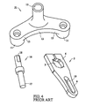
- FIG. 5 in patent no. 6,401,884 shows the connection of the arm 33 having a first end 34 attached to the vane and a second end 35 connected to a pin of the prior art.
- the top of the pin was, in practice, traditionally loosely held in a channel within the arm, and the bottom was loosely held in a cavity within the frame of the motorcycle (or something rigidly attached to the frame of the motorcycle).
- a yoke 21, shown in FIG. 4 and FIG. 5 containing a cavity 15 is utilized to connect the prior-art pin 16 to the frame 100 of a motorcycle 101, as illustrated in FIG. 5 .
- the second end 6 of the arm 2 contains an aperture 19 into which the upper end 18 of the prior-art pin 16 fits.
- the lower end 17 of the prior-art pin 16 is contained within the cavity 15.
- a stable platform preferably a y-shaped yoke, is connected to the frame of the motorcycle as well as to the arm from the wiper.
- the top of the prior-art pin was loosely held in a channel within the arm, and the bottom was, in a first embodiment, loosely held in a cavity within the frame of the motorcycle (or something rigidly attached to the frame of the motorcycle).
- the present platform preferably the yoke, is, however, securely fastened to the frame of the motorcycle (or something rigidly attached to the frame of the motorcycle).
- the top of the platform, preferably the top of the yoke, which holds the arm can be tightened, preferably with a set screw, so that the arm is securely held. Both secure attachments cause the dampening of the front wheel to be more precise.
- the stabilizer and arm can be removed, e.g., for maintenance, without having to remove the yoke, as would be the case with respect to the rigidly connected arm and bracket of United States patent no. 4,773,514 , and without the yoke become unstable, as would the prior-art pin.
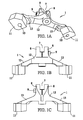
- FIG. 1A is a perspective view from below a preferred embodiment of the platform, i.e., the yoke, for the Pinless Device for Orienting a motorcycle Stabilizer Wiper.
- FIG. 1B is a view of the rear of the yoke of FIG. 1A .
- FIG. 1C is a view of the front of the yoke of FIG. 1A .
- FIG. 1D is a view of the right side of the yoke of FIG. 1A .
- FIG. 1E is a plan view of the yoke of FIG. 1A .
- FIG. 1F is a view of the bottom of the yoke of FIG. 1A .
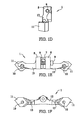
- FIG. 2A is a view of either the top or the bottom (since they are identical) of a preferred arm for a stabilizer.
- FIG. 2B is a view of a first side of the arm for a stabilizer of FIG. 2A .
- FIG. 2C is a view of a first end of the arm for a stabilizer of FIG. 2A .
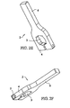
- FIG. 2D is a view primarily of the second end of the arm for a stabilizer of FIG. 2A .
- FIG. 2E is a perspective view from below and to a second side of the arm for a stabilizer of FIG. 2A .
- FIG. 2F is a perspective view from below and to a first side of the arm for a stabilizer of FIG. 2A .
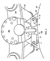
- FIG. 3 is a perspective view from above a preferred embodiment of the Pinless Device for Orienting a Motorcycle Stabilizer Wiper installed on a motorcycle.
- FIG. 4 shows the yoke and pin of a prior-art pin mount for a stabilizer arm as well as the arm, itself.
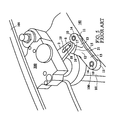
- FIG. 5 is a perspective view from above a prior-art pin mount for a stabilizer arm installed on a motorcycle.
- the present Pinless Device for Orienting a motorcycle Stabilizer Wiper comprises, in a preferred embodiment, the y-shaped yoke 1 of FIG. 1 and the arm 2 of FIG. 2 .
- the arm 2 is attached to the shaft (not illustrated in these two FIGS.) that extends outside the bottom of the housing (not illustrated in these two FIGS.) of the stabilizer 300 and that is connected, within the housing of the stabilizer 300, to the wiper (not illustrated in these two FIGS.).
- a set screw 5, threadedly placed with the first end 4 of the arm 2 so that the set screw 5 can be screwed into the channel 3 while also being partially retained in the first end 4 of the arm 2, is preferably utilized to tighten the first end 4 of the arm 2 about the shaft. (In a lateral view, this connection appears the same as that shown, using the prior-art pin at the second end 6 of the arm 2, in FIG. 5 of patent no. 6,401,884.)
- the second end 6 of the arm 2 is, in the present invention, inserted into the channel 7 that exists between the projections 8 extending, preferably upward, from the yoke 1.
- a set screw 9 threadedly placed in either of the projections 8 so that the set screw 9 can be screwed into the channel 7 while also being partially retained in such projection 8, is utilized to tighten the projections 8 about the second end 6 of the arm 2.
- an aperture 10 exists within each of the bases 11 of the yoke 1.
- the projections 8 preferably rise vertically from a body 12 of the yoke 1.
- Preferably proceeding downward and outward are lateral segments 13 which preferably connect the body 12 to the bases 11.
- fasteners 14 which are preferably screws or bolts passing through the apertures 10, are employed, as shown in FIG. 3 .
- Both the yoke 1 of the preferred embodiment and the yoke 21 of the prior art are preferably attached in front of and near the fuel tank 102 for the motorcycle 101 and behind the handlebar 103 of the motorcycle 101, as illustrated in FIG. 3 and FIG. 5 , respectively.
- the present invention merely requires (1) a mount, which comprises a platform and projections extending from the platform so as to create a channel between such projections, such platform being adapted for stable attachment to a motorcycle; (2) an arm with a first end adapted for attachment to a shaft from a wiper of a motorcycle stabilizer and with a second end of such dimensions that such arm can fit in the channel between the projections; and (3) a means for releasably and securely fastening the second end of such arm between those projections.
Landscapes
- Engineering & Computer Science (AREA)
- Mechanical Engineering (AREA)
- General Engineering & Computer Science (AREA)
- Chemical & Material Sciences (AREA)
- Combustion & Propulsion (AREA)
- Transportation (AREA)
- Axle Suspensions And Sidecars For Cycles (AREA)
Applications Claiming Priority (1)
| Application Number | Priority Date | Filing Date | Title |
|---|---|---|---|
| US11/787,922 US8727658B2 (en) | 2007-04-17 | 2007-04-17 | Pinless device for orienting a motorcycle stabilizer wiper |
Publications (1)
| Publication Number | Publication Date |
|---|---|
| EP1982910A1 true EP1982910A1 (de) | 2008-10-22 |
Family
ID=39434350
Family Applications (1)
| Application Number | Title | Priority Date | Filing Date |
|---|---|---|---|
| EP08154747A Withdrawn EP1982910A1 (de) | 2007-04-17 | 2008-04-17 | Vorrichtung zur Orientierung eines Dämpfungsflügels für ein Motorrad |
Country Status (3)
| Country | Link |
|---|---|
| US (1) | US8727658B2 (de) |
| EP (1) | EP1982910A1 (de) |
| AU (1) | AU2008201619A1 (de) |
Cited By (1)
| Publication number | Priority date | Publication date | Assignee | Title |
|---|---|---|---|---|
| ITMO20110008A1 (it) * | 2011-01-20 | 2012-07-21 | Lusuardi Claudio & C S N C | Dispositivo di attacco per un ammortizzatore di sterzo. |
Families Citing this family (1)
| Publication number | Priority date | Publication date | Assignee | Title |
|---|---|---|---|---|
| CA3198126A1 (en) * | 2022-10-31 | 2024-04-30 | Bombardier Recreational Products Inc. | Personal watercraft with steering damper |
Citations (9)
| Publication number | Priority date | Publication date | Assignee | Title |
|---|---|---|---|---|
| BE346368A (de) * | ||||
| GB259034A (en) * | 1925-10-08 | 1926-10-07 | Alick Darby Draper | Improvements in and connected with damper devices for the steering arrangements of motor cycles and like vehicles |
| WO1986003267A1 (en) * | 1984-11-28 | 1986-06-05 | ALBERTSSON, Per, Ha^okan | Hydraulic damping device |
| US5927740A (en) * | 1996-08-14 | 1999-07-27 | Hopey; Timothy C. | Steering damper in and for vehicles |
| US6401884B2 (en) | 1999-12-28 | 2002-06-11 | Ralph S. Norman | Fluidic dampening device |
| EP1248013A2 (de) * | 2001-04-06 | 2002-10-09 | Honda Giken Kogyo Kabushiki Kaisha | Dämpfer für Lenker |
| US20040211632A1 (en) * | 2003-03-20 | 2004-10-28 | Honda Motor Co., Ltd. | Rotary Damper |
| EP1514786A1 (de) * | 2003-09-09 | 2005-03-16 | HONDA MOTOR CO., Ltd. | Lenkungsdämpfer für Fahrzeug, und damit ausgestattetes Fahrzeug |
| US6899208B2 (en) | 2001-12-17 | 2005-05-31 | Charles N. VanValkenburgh | Rotary damper |
Family Cites Families (1)
| Publication number | Priority date | Publication date | Assignee | Title |
|---|---|---|---|---|
| SE444721B (sv) * | 1982-06-14 | 1986-04-28 | Bofors Ab | Fluiddempningsorgan for dempning av riktrorelser |
-
2007
- 2007-04-17 US US11/787,922 patent/US8727658B2/en not_active Expired - Fee Related
-
2008
- 2008-04-11 AU AU2008201619A patent/AU2008201619A1/en not_active Abandoned
- 2008-04-17 EP EP08154747A patent/EP1982910A1/de not_active Withdrawn
Patent Citations (10)
| Publication number | Priority date | Publication date | Assignee | Title |
|---|---|---|---|---|
| BE346368A (de) * | ||||
| GB259034A (en) * | 1925-10-08 | 1926-10-07 | Alick Darby Draper | Improvements in and connected with damper devices for the steering arrangements of motor cycles and like vehicles |
| WO1986003267A1 (en) * | 1984-11-28 | 1986-06-05 | ALBERTSSON, Per, Ha^okan | Hydraulic damping device |
| US4773514A (en) | 1984-11-28 | 1988-09-27 | Per Hakan Albertsson | Hydraulic damping device |
| US5927740A (en) * | 1996-08-14 | 1999-07-27 | Hopey; Timothy C. | Steering damper in and for vehicles |
| US6401884B2 (en) | 1999-12-28 | 2002-06-11 | Ralph S. Norman | Fluidic dampening device |
| EP1248013A2 (de) * | 2001-04-06 | 2002-10-09 | Honda Giken Kogyo Kabushiki Kaisha | Dämpfer für Lenker |
| US6899208B2 (en) | 2001-12-17 | 2005-05-31 | Charles N. VanValkenburgh | Rotary damper |
| US20040211632A1 (en) * | 2003-03-20 | 2004-10-28 | Honda Motor Co., Ltd. | Rotary Damper |
| EP1514786A1 (de) * | 2003-09-09 | 2005-03-16 | HONDA MOTOR CO., Ltd. | Lenkungsdämpfer für Fahrzeug, und damit ausgestattetes Fahrzeug |
Cited By (1)
| Publication number | Priority date | Publication date | Assignee | Title |
|---|---|---|---|---|
| ITMO20110008A1 (it) * | 2011-01-20 | 2012-07-21 | Lusuardi Claudio & C S N C | Dispositivo di attacco per un ammortizzatore di sterzo. |
Also Published As
| Publication number | Publication date |
|---|---|
| US20110097143A1 (en) | 2011-04-28 |
| US8727658B2 (en) | 2014-05-20 |
| AU2008201619A1 (en) | 2008-11-06 |
Similar Documents
| Publication | Publication Date | Title |
|---|---|---|
| US7681901B2 (en) | Gauge mount for motorcycle | |
| US20030062456A1 (en) | Mounting structure | |
| US20160194053A1 (en) | Mounting system for attaching an electric system to bicylces | |
| EP1982910A1 (de) | Vorrichtung zur Orientierung eines Dämpfungsflügels für ein Motorrad | |
| EP1935718A2 (de) | Vorrichtung mit einer Spiegelanordnung | |
| US20100181146A1 (en) | Oil Pan for Internal Combustion Engine Transmission Unit | |
| GB2343712A (en) | Door closer : mounting | |
| JP6893101B2 (ja) | 自転車用ディスクブレーキのキャリパーグループ、およびキャリパーグループを自転車の耐荷重エレメントに取り付ける方法 | |
| CN104129265B (zh) | 用于机动车的动力总成的悬置装置 | |
| AU2011235956A1 (en) | Pinless device for orienting a motorcycle stabilizer wiper | |
| CN114094516B (zh) | 一种汽车轮速传感器线束总成 | |
| DE102004022720A1 (de) | Abgasanlage für eine durch Getriebe und Motor gebildete Antriebseinheit | |
| CN222080855U (zh) | 吊架、自行车和中置电机 | |
| AU2003204918B2 (en) | Mounting device | |
| EP1254793A3 (de) | Buchse und Radaufhängungsanordnung | |
| CN203739582U (zh) | 空调压缩机的安装装置 | |
| JPH11115856A (ja) | 自動二輪車のメータケース取付け構造 | |
| CN117360677B (zh) | 吊架、自行车和中置电机 | |
| SE1251313A1 (sv) | Anordning vid bergborrmaskin | |
| EP2528779B1 (de) | Aussenspiegeleinheit, verfahren zur montage einer aussenspiegeleinheit | |
| US20030161736A1 (en) | Pump device unifying a reservoir and method for attaching the reservoir to the pump device | |
| US20080191444A1 (en) | Motorcycle rear wheel trim assembly | |
| WO2025103449A1 (en) | A bicycle frame comprising a stem assembly and a top tube | |
| CN203634570U (zh) | 输液泵悬挂装置 | |
| KR200299060Y1 (ko) | 스쿠터의 핸들서포터 회전방지구조 |
Legal Events
| Date | Code | Title | Description |
|---|---|---|---|
| PUAI | Public reference made under article 153(3) epc to a published international application that has entered the european phase |
Free format text: ORIGINAL CODE: 0009012 |
|
| AK | Designated contracting states |
Kind code of ref document: A1 Designated state(s): AT BE BG CH CY CZ DE DK EE ES FI FR GB GR HR HU IE IS IT LI LT LU LV MC MT NL NO PL PT RO SE SI SK TR |
|
| AX | Request for extension of the european patent |
Extension state: AL BA MK RS |
|
| 17P | Request for examination filed |
Effective date: 20090415 |
|
| 17Q | First examination report despatched |
Effective date: 20090514 |
|
| AKX | Designation fees paid |
Designated state(s): AT BE BG CH CY CZ DE DK EE ES FI FR GB GR HR HU IE IS IT LI LT LU LV MC MT NL NO PL PT RO SE SI SK TR |
|
| STAA | Information on the status of an ep patent application or granted ep patent |
Free format text: STATUS: THE APPLICATION IS DEEMED TO BE WITHDRAWN |
|
| 18D | Application deemed to be withdrawn |
Effective date: 20131101 |