EP1982627B1 - Reinigungskörper und reinigungswerkzeug - Google Patents
Reinigungskörper und reinigungswerkzeug Download PDFInfo
- Publication number
- EP1982627B1 EP1982627B1 EP07708151.1A EP07708151A EP1982627B1 EP 1982627 B1 EP1982627 B1 EP 1982627B1 EP 07708151 A EP07708151 A EP 07708151A EP 1982627 B1 EP1982627 B1 EP 1982627B1
- Authority
- EP
- European Patent Office
- Prior art keywords
- cleaning element
- cleaning
- tubular part
- fiber bundle
- brush
- Prior art date
- Legal status (The legal status is an assumption and is not a legal conclusion. Google has not performed a legal analysis and makes no representation as to the accuracy of the status listed.)
- Not-in-force
Links
Images


Classifications
-
- A—HUMAN NECESSITIES
- A47—FURNITURE; DOMESTIC ARTICLES OR APPLIANCES; COFFEE MILLS; SPICE MILLS; SUCTION CLEANERS IN GENERAL
- A47L—DOMESTIC WASHING OR CLEANING; SUCTION CLEANERS IN GENERAL
- A47L13/00—Implements for cleaning floors, carpets, furniture, walls, or wall coverings
- A47L13/10—Scrubbing; Scouring; Cleaning; Polishing
- A47L13/20—Mops
-
- A—HUMAN NECESSITIES
- A47—FURNITURE; DOMESTIC ARTICLES OR APPLIANCES; COFFEE MILLS; SPICE MILLS; SUCTION CLEANERS IN GENERAL
- A47L—DOMESTIC WASHING OR CLEANING; SUCTION CLEANERS IN GENERAL
- A47L13/00—Implements for cleaning floors, carpets, furniture, walls, or wall coverings
- A47L13/10—Scrubbing; Scouring; Cleaning; Polishing
- A47L13/16—Cloths; Pads; Sponges
-
- A—HUMAN NECESSITIES
- A47—FURNITURE; DOMESTIC ARTICLES OR APPLIANCES; COFFEE MILLS; SPICE MILLS; SUCTION CLEANERS IN GENERAL
- A47L—DOMESTIC WASHING OR CLEANING; SUCTION CLEANERS IN GENERAL
- A47L13/00—Implements for cleaning floors, carpets, furniture, walls, or wall coverings
- A47L13/10—Scrubbing; Scouring; Cleaning; Polishing
- A47L13/38—Other dusting implements
Definitions
- the present invention relates to a cleaning tool, and more particularly to a cleaning tool having a cleaning element for cleaning a face to be cleaned inside a room or a vehicle.
- an object of the present invention to provide an effective technique for reducing the manufacturing costs in a cleaning tool having a cleaning element for cleaning a face to be cleaned.
- This invention can be applied to the construction of cleaning tools for cleaning faces to be cleaned (floors, walls, ceilings, external walls, furniture, clothes, curtains, bedding, home electric appliances, etc.) inside and outside of houses, apartments, buildings, factories, vehicles, etc. or faces of human body parts to be cleaned. These faces to be cleaned may be either flat or curved, uneven or stepped.
- the cleaning element according to this invention is provided in order to solve the above-described problem.
- the cleaning element has a layer structure with a fiber bundle and a non-woven fabric laminated together.
- the cleaning element includes at least a tubular part, a receiving space, a brush part and a hardened part.
- the non-woven fabric in this invention has a sheet-like configuration formed by fixing or entangling fibers by mechanical, chemical or heat treatment.
- the non-woven fabric partly includes thermoplastic fibers and thus can be fusion bonded.
- the “fibers” in this invention are elements of yarn, textile or the like and defined as being thin and flexible fibers having a substantially longer length compared with the thickness.
- a long continuous fiber is defined as a filament and a short fiber as a staple.
- the "fiber bundle” in this invention is a single fiber structure formed by the above-mentioned fibers, a fiber structure having the above-mentioned fibers aligned in the length direction and/or the radial direction (twist yarn, spun yarn, yarn to which a plurality of filaments are partially connected), or an assembly of the fiber structures.
- the fiber bundle is formed of polyethylene (PE), polypropylene (PP), polyethylene terephthalate (PET), nylon, rayon or the like. In practical use, an assembly of filaments formed by opening a tow is frequently used as the fiber bundle.
- the tubular part in this invention is a long part formed by folding back the cleaning element into a tubular shape such that the fiber bundle of the cleaning element is located inside.
- the sectional shape of the tubular part widely includes circular, elliptical, triangular, rectangular, polygonal and other various shapes. Further, the tubular part may have a closed section or an open section which is not completely closed.
- the receiving space in this invention is defined inside the tubular part and configured as a region (space) in which a holding part for holding the cleaning element is removably received.
- a holding part for holding the cleaning element is held by the holding part. Further, the user can replace the cleaning element by removing the cleaning element from the holding part as necessary.
- the cleaning element according to this invention may be of disposable type designed for single use, disposable type designed for multiple use which can be used several times, while retaining dust which has been removed from the face to be cleaned, on a brush part, or reusable type which can be reused by washing.
- the brush part in this invention forms a brush-like cleaning area in a region of the cleaning element other than the tubular part.
- the brush part has the fiber bundle on the inner side and the non-woven fabric on the outer side (top).
- the brush part having such a construction is effective in sweeping away dirt and dust on the face to be cleaned.
- the non-woven fabric of the brush part may be preferably configured as strips, and more preferably, the strips of the non-woven fabric may have a zigzag shape which can easily trap dust.
- a hardened part is provided in the cleaning element.
- the hardened part is formed by hardening a portion of the fiber bundle which is disposed in the receiving space.
- the fiber bundle subjected to a hardening process may be in a hardened state, or may have some softness.
- the hardening process may be appropriately performed by heat treatment (heating, fusion bonding), application of an adhesive or other similar process.
- the inner wall surface of the receiving space can be subjected to this hardening process in a continuous or discontinuous manner in its entirety or in part. If the inner wall surface of the receiving space is subjected to the hardening process in part, the areas to be subjected to the process can be appropriately selected as necessary, such as end portions of the tubular part, upper and lower portions of the inner wall surface of the receiving space, and left and right portions of the inner wall surface of the receiving space.
- the cleaning element having the hardened part by provision of the cleaning element having the hardened part, the inner wall surface of the receiving space can be formed by the fiber bundle itself without using other hard material. Therefore, the number of materials forming the layer structure of the cleaning element can be reduced, so that the cleaning tool can be provided with a rational construction which is reduced in manufacturing costs.
- the brush part may extend from the long tubular part extending along the extending direction of the holding part, in a direction transverse to the extending direction of the tubular part.
- the "extending direction of the brush part" here is defined as a direction in which fibers of the fiber bundle forming the brush part extend. It is only necessary for the extending direction of the brush part to be a direction transverse to the extending direction of the tubular part. Therefore, the extending direction widely includes not only the direction generally perpendicular to the extending direction of the tubular part, but a direction inclined at a predetermined angle with respect to the extending direction of the tubular part.
- the brush part when the tubular part is disposed horizontally, the brush part can be arranged to extend vertically downward from the tubular part. Therefore, the fibers of the brush part can be effectively used for cleaning, so that the action of sweeping away dirt and dust on the face to be cleaned can be easily performed.
- the fiber bundle may face the side of the brush part which faces the face to be cleaned and the tubular part is disposed on the face of the brush part which faces away from the face to be cleaned.
- the cleaning element is provided in which the tubular part is disposed on the side of the brush part opposite to the face to be cleaned.
- the long tubular part may be bent at a predetermined point in its longitudinal direction into a U-shape such that two receiving spaces for receiving the holding part are formed in both end portions of the tubular part.
- the cleaning element can be provided in which the long tubular part is U-shaped such that two receiving spaces for receiving the holding part are formed in both end portions of the tubular part.
- a cleaning tool which includes at least a cleaning element, a receiving space, a holding part and a grip part.
- the cleaning element further includes at least a tubular part, a brush part and a hardened part.
- the cleaning element has a layer structure with a fiber bundle and a non-woven fabric laminated together.
- the receiving space is provided in the cleaning element, and the holding part is removably received in the receiving space of the cleaning element and serves to hold the cleaning element.
- the grip part is connected to the holding part and designed to be held by a user.
- the cleaning element of the cleaning tool according to this invention includes a long tubular part which is formed into a tubular shape by folding back the cleaning element with the fiber bundle located inside and thus forms the receiving space, a brush part which forms a brush-like cleaning area in a region of the cleaning element other than the tubular part, and a hardened part which is formed by hardening a portion of the fiber bundle which is disposed in the receiving space.
- the cleaning element having the hardened part by provision of the cleaning element having the hardened part, the inner wall surface of the receiving space can be formed by the fiber bundle itself without using other hard material. Therefore, the number of materials forming the layer structure of the cleaning element can be reduced, so that the cleaning tool can be provided with a rational construction which is reduced in manufacturing costs.
- the extending directions of the holding part, the grip part and the tubular part may generally coincide with each other.
- the brush part of the cleaning element may extend from the long tubular part in a direction transverse to the extending direction of the tubular part.
- the brush part may extend transverse to the holding part, the grip part and the tubular part.
- the brush part when the holding part, the grip part and the tubular part are disposed horizontally, the brush part can be arranged to extend vertically downward from the tubular part. Therefore, the fibers of the brush part can be effectively used for cleaning, so that the action of sweeping away dirt and dust on the face to be cleaned can be easily performed.
- the fiber bundle may face the side of the brush part of the cleaning element which faces the face to be cleaned and the tubular part may be disposed on the face of the brush part which faces away from the face to be cleaned.
- the cleaning tool is provided with the cleaning element in which the tubular part is disposed on the side of the brush part opposite to the face to be cleaned.
- the long tubular part of the cleaning element may be bent at a predetermined point in its longitudinal direction into a U-shape such that two receiving spaces are formed in both end portions of the tubular part.
- the cleaning tool can be provided with the cleaning element in which the long tubular part is U-shaped such that two receiving spaces for receiving the holding part are formed in both end portions of the tubular part.
- the cleaning element and the cleaning tool can be provided with a rational construction which is reduced in manufacturing costs.
- Faces to be cleaned with the cleaning tool 10 includes faces to be cleaned (floors, walls, windows, ceilings, external walls, furniture, clothes, curtains, bedding, lighting, home electric appliances, etc.) inside and outside of houses, apartments, buildings, factories, vehicles, etc. and faces of human body parts to be cleaned. These faces to be cleaned may be either flat or curved, uneven or stepped.
- FIG. 1 shows the cleaning tool 10 according to this embodiment in perspective view
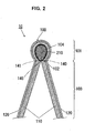
- FIG. 2 is a sectional view taken along line A-A in FIG. 1
- the cleaning tool 10 comprises the cleaning element 100 and a holder 200.
- the cleaning element 100 in this embodiment is formed from a sheet-type fiber bundle 110 and a sheet-type non-woven fabric 120 laminated and joined together at bonding lines 140, 141, 142, 143, 144, 145.
- the cleaning element 100 includes a tubular part 101 and a brush part 103.
- the cleaning element 100 is a feature that corresponds to the "cleaning element” according to this invention.
- the tubular part 101 and the brush part 103 are features that correspond to the "tubular part” and the "brush part", respectively, according to this invention.
- the tubular part 101 includes a hollow tubular receiving space 102 (also referred to as an "internal space").
- the receiving space 102 is a feature that corresponds to the "receiving space” according to this invention.
- the brush part 103 forms a brush-like cleaning part in a region of the cleaning element other than the tubular part 101. Both the tubular part 101 and the brush part 103 have the fiber bundle on the inner side and the non-woven fabric 120 on the outer side (top). Further, in the cleaning element 100 in this embodiment, the fiber bundle 110 faces the side of the brush part 103 which faces the face to be cleaned.
- the tubular part 101 is disposed on the face of the brush part 103 which faces away from the face to be cleaned.
- the brush part 103 extends vertically downward from the tubular part 101 when the holder 200 extends horizontally or a holding part 210 and a grip part 220 which are described below extend substantially horizontally.
- This horizontally extending state of the holder 200 coincides with the state of the holder 200 with the grip part (the grip part 220 described below) held by the user for cleaning operation. Therefore, the brush part 103 tends to extend downward, which allows full use of the fibers of the brush part 103 and is thus effective in sweeping away dirt and dust on the face to be cleaned.
- the fiber bundle 110 is a single fiber structure formed by fibers, a fiber structure having fibers aligned in the length direction and/or the radial direction (twist yarn, spun yarn, yarn to which a plurality of filaments are partially connected), or an assembly of the fiber structures.
- the fiber bundle 110 partially includes thermoplastic fibers and can be fusion bonded.
- the fibers forming the fiber bundle 110 are elements of yarn, textile or the like and defined as being thin and flexible fibers having a substantially longer length compared with the thickness. Typically, a long continuous fiber is defined as a filament and a short fiber as a staple.
- the fiber bundle 110 is a feature that corresponds to the "fiber bundle" according to this invention.
- the fiber bundle 110 is typically formed of polyethylene (PE), polypropylene (PP), polyethylene terephthalate (PET), nylon, rayon or the like. In practical use, an assembly of filaments formed by opening a tow is frequently used as the fiber bundle 110. It is particularly preferable that the fiber bundle 110 comprises conjugated fibers having a core of polypropylene (PP) or polyethylene (PE) and a core covering sheath of polyethylene (PE). Further, it is preferable for the filaments of the fiber bundle 110 to have a fineness of 1 to 50 dtex, and more preferably 2 to 10 dtex. The individual fiber bundle may contain fibers of generally the same fineness or of different finenesses. Further, in order to enhance the sweeping function, it is preferred to use a fiber bundle including fibers having higher rigidity or fibers having higher fineness.
- flat yarns or split yarns may be employed as the fiber bundle 110.
- the flat yarns are prepared by slitting a film into tapes and by stretching the tapes in the longitudinal direction.
- the split yarns are prepared by splitting a thermoplastic film resin in the direction perpendicular to the orientation direction of the resin so that the film is fibrillated and interconnected into a net shape.
- a non-woven fabric which is bulky and has low fiber density, such as a through-air bonded non-woven fabric, may be employed to form the fiber bundle 110.
- the fiber bundle 110 may be formed by using crimped fibers.
- the crimped fibers are fibers subjected to a predetermined crimping process. With the fibers being crimped, the fiber bundle becomes bulky, and dust can be easily captured by the crimped portions. This structure can be realized especially by using crimped fibers opened from a tow.
- the cleaning element 100 in this embodiment can perform a higher cleaning function since dirt is entangled between the fibers of the fiber bundle 110 or on the crimped portions of the fibers during cleaning operation using the cleaning element 100.
- the non-woven fabric 120 has a sheet-like configuration formed by fixing or entangling fibers by mechanical, chemical or heat treatment.
- the non-woven fabric 120 partly includes thermoplastic fibers and thus can be fusion bonded. Further, the non-woven fabric 120 has a plurality of strips.
- the non-woven fabric 120 is a feature that corresponds to the "non-woven fabric" according to this embodiment.
- the non-woven fabric 120 may be manufactured by spun bonding, through-air bonding, thermal bonding, spun lacing, point bonding, melt blowing, stitch bonding, chemical bonding, needle punching or other similar processes. In order to enhance the sweeping function in cleaning operation, it is preferred to use a non-woven fabric having higher rigidity.
- the strips of the non-woven fabric 120 may have various shapes, such as zigzag and curved shapes. In order to enhance the cleaning function, preferably, the strips may have a zigzag shape which can easily trap dust.
- urethane, sponge, woven fabric, net, split cloth or other similar material may also be used in the form of strips.
- the cleaning element 100 in this embodiment can perform a higher cleaning function since dust is trapped between the strips or on the faces of the strips during cleaning operation using the cleaning element 100.
- the non-woven fabric 120 has higher rigidity than the fiber bundle 110 and thus can perform a function of preventing the fiber bundle 120 from being fixed or entangled with each other. If the non-woven fabric 120 is formed by using crimped fibers, the non-woven fabric 120 disposed on the outer surface of the tubular part 101 can also be provided with a cleaning function.
- the holder 200 has a function of holding the cleaning element 100 having the above-described function and includes at least an elongate holding part 210 and an elongate grip part 220.
- the holding part 210 is disposed on the front end of the grip part 220.
- the holding part 210 is removably inserted into the receiving space 102 of the tubular part 101 of the cleaning element 100 and serves to hold the cleaning element 100.
- the holding part 210 is configured as one rod-like or plate-like part.
- the grip part 220 is connected to and extends from the rear end of the holding part 210 and held by the user's hand during cleaning operation or replacement of the cleaning element.
- the extending directions of the holding part 210 and the grip part 220 generally coincide with each other.
- the holding part 210 and the grip part 220 may be formed separately and assembled together. Alternatively, they may be integrally formed.
- the user can replace the cleaning element 100 by removing the cleaning element 100 from the holding part 210 as necessary.
- the cleaning element 100 may be of disposable type designed for single use, disposable type designed for multiple use which can be used several times, while retaining dust which has been removed from the face to be cleaned, on a brush part, or reusable type which can be reused by washing.
- the inner surface of the fiber bundle 110 which defines the receiving space 102 is subjected to a hardening process and thus forms a hardened part 104.
- the hardened part 104 is a feature that corresponds to the "hardened part" in this invention.
- stretch materials 130 are mounted on the both ends of the receiving space 102 of the tubular part 101.
- Each of the stretch materials 130 is a non-woven fabric at least partly including thermoplastic fiber, or a thermoplastic resin film, and is formed of materials having a stretching function, or of non-woven fabric containing a elastomer material, or of elastomer, urethane, rubber, etc.
- FIGS. 3 and 4 show the process of manufacturing the cleaning element 100 according to this embodiment.
- the cleaning element 100 shown in FIG. 1 can be manufactured at least by performing the first bonding process, the hardening process, the folding process and the second bonding process in this order.
- the fiber bundle 110 having the above described construction and the strip-like non-woven fabric 120 are laminated and joined together.
- the fiber bundle 110 and the non-woven fabric 120 are first fusion bonded together at the bonding lines 140, 141.
- the fiber bundle 110 and the non-woven fabric 120 are fusion bonded in a pattern at the bonding line 142 on the portion of the fiber bundle 110 which is surrounded by the bonding lines 140, 141.
- the bonding line 142 can also be designed to be parallel to the bonding lines 140, 141.
- the both ends of the fiber bundle 110 and the non-woven fabric 120 are fusion bonded together at the bonding lines 143, 144.
- a fiber sheet of a two-layer structure consisting of the fiber bundle 110 and the non-woven fabric 120 is formed.
- the stretch materials 130 are bonded to the both ends of the non-woven fabric 120.
- the entire inner surface of the fiber bundle 110 which defines the receiving space 102 in the fiber sheet obtained by the first bonding process is subjected to a hardening process (heat treatment) and thus forms the hardened part 104.
- a hardening process heat treatment
- the hardening process may also be performed by application of an adhesive or other similar process instead of heat treatment.
- the inner wall surface of the receiving space 102 can be subjected to this hardening process in a continuous or discontinuous manner in its entirety or in part.
- the areas to be subjected to the process can be appropriately selected as necessary, such as end portions of the tubular part 101, upper and lower portions of the inner wall surface of the receiving space 102, and left and right portions of the inner wall surface of the receiving space 102.
- the fiber sheet obtained by the hardening process is folded back along the bonding lines 140, 141 in such a manner as to form a tubular shape and such that the fiber bundle 110 is located inside.
- a folded fiber sheet of a two-layer structure consisting of the fiber bundle 110 and the non-woven fabric 120 is formed.
- the folded portions of the folded fiber sheet obtained by the folding process are fusion bonded together at the bonding line 145.
- the cleaning element 100 as shown in FIG. 1 is obtained having the hollow tubular part 101 with the closed circular receiving space 102 and the brush part 103 formed in a region of the cleaning element other than the tubular part 101.
- the bonding lines 140 to 145 may have a continuous linear or curved shape or a discontinuous linear or curved shape.
- the cleaning element 100 of this embodiment is of a two-layer structure consisting of the fiber bundle 110 and the non-woven fabric 120. Therefore, the number of parts and thus the manufacturing costs can be effectively reduced.
- FIG. 5 is a perspective view showing a cleaning tool 20 having a holder 300 which includes a grip part 320 and two parallel holding parts 310 connected to the front end of the grip part 320.
- the tubular part 101 of the cleaning element 100 obtained in the above-described second bonding process is pressed at the top along the length of the tubular part down in the direction of the arrow in FIG. 5 .
- the one tubular portion of the tubular part 101 is divided into two tubular portions and the pressed portion is bonded.
- the cleaning element 100 can be provided with the tubular part 101 having two receiving spaces 102a, 102b as shown by solid lines in FIG. 5 .
- the holding parts 310 (the "holding part” according to this invention) connected to the front end of the grip part 320 (the “grip part” according to this invention) are inserted into the receiving spaces 102a, 102b (the “receiving space” or the “two receiving spaces” according to this invention) of the cleaning element 100.
- the cleaning tool 20 (the “cleaning tool” according to this invention) shown in FIG. 5 is formed. Due to the increased number of the holding parts, the holder 300 having such a construction has an advantageous effect that the cleaning element 100 held by the holder 300 does not easily come off during use.
- FIGS. 6 and 7 are perspective views of the cleaning elements 100 formed by different methods from that of FIG. 5 and having two receiving spaces 102a, 102b in the tubular part 101.
- the cleaning element 100 as shown in FIG. 1 is bent 180 degrees at a central region 105 so that the tubular part 101 is U-shaped. As a result, the both end portions of the tubular part 101 can be used as the receiving spaces 102a, 102b.
- two cleaning elements 100 as shown in FIG. 1 are provided and disposed in parallel. As a result, the receiving space of one of the cleaning elements 100 can be used as the receiving space 102a, while the receiving space of the other cleaning element 100 can be used as the receiving space 102b.
- the methods shown in FIGS. 6 and 7 like the method shown in FIG. 5 , can achieve the effect that the cleaning element 100 held by the holder 300 does not easily come off during use. Further, by using the method shown in FIG. 7 , the volume of the brush part 103 is further increased, so that the cleaning effect can be increased.
- the cleaning element 100 in the above embodiment is described as having a two-layer structure consisting of the fiber bundle 110 and the non-woven fabric 120, it can have a multilayer structure having another fiber layer in addition to the fiber bundle 110 and the non-woven fabric.
- a three-layer structure can be used having the fiber bundle 110 and the non-woven fabrics 120 arranged on the both sides of the fiber bundle 110.
- the fiber bundle 110 which can easily contain air between fibers is sandwiched between the non-woven fabrics 120, so that the three layer can be fusion bonded while air inside the fiber bundle 110 is squeezed out as much as possible.
- the fusion bonding performance can be enhanced.
- the brush part 103 of the cleaning element 100 is described as extending vertically downward from the tubular part 101 when the holder 200 extends horizontally.
- various changes can be made in the extending direction of the brush part 103.
- the brush part 103 can be inclined a predetermined angle with respect to the extending direction of the tubular part 101, or the brush part 103 can extend laterally from the both sides of the tubular part 101.
Landscapes
- Cleaning Implements For Floors, Carpets, Furniture, Walls, And The Like (AREA)
- Preliminary Treatment Of Fibers (AREA)
Claims (8)
- Reinigungselement (100), das Folgendes umfasst:ein langes rohrförmiges Teil (101),einen Aufnahmeraum (102), der innerhalb des rohrförmigen Teils definiert ist, und in dem ein Halterungsteil (210) zum Befestigen des Reinigungselements entfernbar aufgenommen wird, undein Bürstenteil (103), dadurch gekennzeichnet, dassdas Reinigungselement eine Schichtstruktur mit einem Faserbündel (110) und einem Vliesstoff (120) hat, die zusammenlaminiert sind,wobei das lange rohrförmige Teil in eine rohrförmige Form gebildet wird, indem das Reinigungselement so zurückgefaltet wird, dass das Faserbündel des Reinigungselements innen angebracht ist,das Bürstenteil, das einen bürstenartigen Reinigungsbereich in einem Bereich des Reinigungselements außer des röhrförmigen Teils bildet, und ferner Folgendes umfasst:ein gehärtetes Teil (104), das durch Härten eines Abschnitts des Faserbündels gebildet wird, das im Aufnahmeraum angeordnet ist.
- Reinigungselement nach Anspruch 1, wobei sich das Bürstenteil vom langen röhrförmigen Teil (101) erstreckt, und sich in Erstreckungsrichtung des Halterungsteils (200) in Querrichtung zur Erstreckungsrichtung des rohrförmigen Teils erstreckt.
- Reinigungselement nach Anspruch 1 oder 2, wobei das Faserbündel (110) der Seite des Bürstenteils (103) gegenübersteht, das einer Fläche gegenübersteht, die gereinigt werden muss, und das rohrförmige Teil auf der Fläche des Bürstenteils angeordnet ist, die von der zu reinigenden Fläche abgewendet ist.
- Reinigungselement nach einem der Ansprüche 1 bis 3, wobei das lange rohrförmige Teil (101) an einem vorbestimmten Punkt in seiner Längsrichtung in eine U-Form gebogen ist, sodass zwei Aufnahmeräume (1 02a, 102b) zur Aufnahme des Halterungsteils (300) in beiden Endabschnitten des rohrförmigen Teils gebildet sind.
- Reinigungswerkzeug (10), das Folgendes umfasst:ein Reinigungselement (100) nach einem der vorangehenden Ansprüche, wobeiein Halterungsteil (210), das entfernbar im Aufnahmeraum (102) des Reinigungselements aufgenommen wird und zum Halten des Reinigungselements dient, undein Greifteil (220), das mit dem Halterungsteil (210) verbunden ist und so entworfen ist, dass es von einem Benutzer gehalten wird.
- Reinigungswerkzeug nach Anspruch 5, wobei die Erstreckungsrichtungen des Halterungsteils (210), das Greifteil (220) und das röhrförmige Teil (101) allgemein miteinander übereinstimmen, und wobei sich das Bürstenteil des Reinigungselements vom langen rohrförmigen Teil in einer Richtung erstreckt, die quer zur Erstreckungsrichtung des rohrförmigen Teils liegt.
- Reinigungswerkzeug nach Anspruch 5 oder 6, wobei das Faserbündel (110) der Seite des Bürstenteils des Reinigungselements gegenübersteht, das einer Fläche gegenübersteht, die gereinigt werden soll, und das rohrförmige Teil auf der Fläche des Bürstenteils angeordnet ist, die von der zu reinigenden Fläche abgewendet ist.
- Reinigungswerkzeug nach einem der Ansprüche 5 bis 7, wobei das lange rohrförmige Teil (101) des Reinigungselements an einem vorbestimmten Punkt in seiner Längsrichtung in eine U-Form gebogen ist, sodass zwei Aufnahmeräume in beiden Endabschnitten des rohrförmigen Teils gebildet sind.
Applications Claiming Priority (2)
| Application Number | Priority Date | Filing Date | Title |
|---|---|---|---|
| JP2006031121A JP4845525B2 (ja) | 2006-02-08 | 2006-02-08 | 清掃体及び清掃用具 |
| PCT/JP2007/052112 WO2007091592A1 (ja) | 2006-02-08 | 2007-02-07 | 清掃体及び清掃用具 |
Publications (3)
| Publication Number | Publication Date |
|---|---|
| EP1982627A1 EP1982627A1 (de) | 2008-10-22 |
| EP1982627A4 EP1982627A4 (de) | 2010-04-07 |
| EP1982627B1 true EP1982627B1 (de) | 2013-08-07 |
Family
ID=38345188
Family Applications (1)
| Application Number | Title | Priority Date | Filing Date |
|---|---|---|---|
| EP07708151.1A Not-in-force EP1982627B1 (de) | 2006-02-08 | 2007-02-07 | Reinigungskörper und reinigungswerkzeug |
Country Status (6)
| Country | Link |
|---|---|
| US (1) | US9089252B2 (de) |
| EP (1) | EP1982627B1 (de) |
| JP (1) | JP4845525B2 (de) |
| CN (1) | CN101378689B (de) |
| TW (1) | TW200733927A (de) |
| WO (1) | WO2007091592A1 (de) |
Families Citing this family (29)
| Publication number | Priority date | Publication date | Assignee | Title |
|---|---|---|---|---|
| US20080028560A1 (en) * | 2006-08-07 | 2008-02-07 | Nicola John Policicchio | Duster system for damp and dry dusting |
| JP5171347B2 (ja) * | 2008-03-31 | 2013-03-27 | ユニ・チャーム株式会社 | 清掃用具 |
| JP5171348B2 (ja) * | 2008-03-31 | 2013-03-27 | ユニ・チャーム株式会社 | 清掃用具、清掃体 |
| US9113768B2 (en) * | 2008-04-16 | 2015-08-25 | Kao Corporation | Cleaning sheet and process for producing the same |
| JP5818406B2 (ja) * | 2010-02-26 | 2015-11-18 | 大王製紙株式会社 | 掃除具 |
| US20110225756A1 (en) * | 2010-03-19 | 2011-09-22 | Quickie Manufacturing Corporation | Cleaning tool with multiple cleaning surfaces |
| US8627829B2 (en) | 2010-12-31 | 2014-01-14 | Goody Products, Inc. | Water removing hair brush |
| USD709291S1 (en) | 2011-12-30 | 2014-07-22 | Goody Products, Inc. | Hair brush |
| ITMI20121738A1 (it) * | 2012-10-16 | 2014-04-17 | Orlandi Spa | Strumento per la pulizia di superfici |
| USD758740S1 (en) | 2012-12-28 | 2016-06-14 | Goody Products, Inc. | Water removing hair brush |
| US20140182767A1 (en) | 2012-12-29 | 2014-07-03 | Unicharm Corporation | Method of producing cleaning member |
| JP6057707B2 (ja) | 2012-12-29 | 2017-01-11 | ユニ・チャーム株式会社 | 開繊された繊維束の製造方法、清掃部材の製造方法、繊維束の開繊装置、及び清掃部材の製造システム |
| JP6080550B2 (ja) | 2012-12-29 | 2017-02-15 | ユニ・チャーム株式会社 | 帯状シートにシールを施す融着装置 |
| US10098516B2 (en) | 2012-12-29 | 2018-10-16 | Unicharm Corporation | Method for producing cleaning member, and system for producing cleaning member |
| JP6047401B2 (ja) | 2012-12-29 | 2016-12-21 | ユニ・チャーム株式会社 | 開繊された繊維束の製造方法、清掃部材の製造方法、繊維束の開繊装置、及び清掃部材の製造システム |
| US20140187406A1 (en) | 2012-12-29 | 2014-07-03 | Unicharm Corporation | Method of producing cleaning member |
| JP6047400B2 (ja) | 2012-12-29 | 2016-12-21 | ユニ・チャーム株式会社 | 清掃部材を製造する方法及び装置 |
| JP6073128B2 (ja) | 2012-12-29 | 2017-02-01 | ユニ・チャーム株式会社 | 切断装置及び切断装置を用いた清掃部材の製造方法 |
| JP6037828B2 (ja) | 2012-12-29 | 2016-12-07 | ユニ・チャーム株式会社 | 開繊された繊維束の製造方法、清掃部材の製造方法、繊維束の開繊装置、及び清掃部材の製造システム |
| JP6141023B2 (ja) | 2013-01-10 | 2017-06-07 | ユニ・チャーム株式会社 | トウを含むウエブ部材の製造方法 |
| JP6103945B2 (ja) | 2013-01-10 | 2017-03-29 | ユニ・チャーム株式会社 | 積み重ね装置及びウェブ部材を製造する方法 |
| JP6323981B2 (ja) * | 2013-02-07 | 2018-05-16 | ユニ・チャーム株式会社 | 清掃具 |
| JP6126398B2 (ja) * | 2013-02-07 | 2017-05-10 | ユニ・チャーム株式会社 | 清掃具 |
| JP6228366B2 (ja) * | 2013-02-07 | 2017-11-08 | ユニ・チャーム株式会社 | 清掃具 |
| CA2912250A1 (en) * | 2013-04-05 | 2014-10-09 | Shikibo Ltd. | Composite lightweight fitting |
| KR102049613B1 (ko) * | 2013-07-10 | 2019-11-28 | 쓰리엠 이노베이티브 프로퍼티즈 캄파니 | 변기용 수세미 및 이를 포함하는 변기용 청소도구 |
| EP3269285B1 (de) * | 2015-03-12 | 2019-07-31 | Uni-Charm Corporation | Reinigungstuch und reinigungsinstrument |
| USD799130S1 (en) * | 2016-05-26 | 2017-10-03 | Sharkninja Operating Llc | Pad |
| CN108042065B (zh) * | 2017-12-11 | 2020-11-06 | 福州永乐食品有限公司 | 一种多功能洁具 |
Family Cites Families (10)
| Publication number | Priority date | Publication date | Assignee | Title |
|---|---|---|---|---|
| GB126138A (en) * | 1918-05-03 | 1919-05-05 | Henry Sidebottom | Improvements in or relating to Dusters, Polishers and the like. |
| US3066344A (en) | 1959-02-27 | 1962-12-04 | Borras Jose Garcia | Dust removers |
| JPS4838306Y1 (de) | 1968-09-21 | 1973-11-13 | ||
| JP2977477B2 (ja) | 1995-12-08 | 1999-11-15 | 花王株式会社 | 清掃具 |
| DE19835735A1 (de) * | 1998-08-07 | 2000-02-17 | Lutz Bengsch | Reinigungsgerät zum Reinigen schmaler Zwischenräume |
| TW200303183A (en) * | 2002-02-22 | 2003-09-01 | Yamada Chiyoe | Cleaning tool, and method for manufacturing cleaning portion constituting the cleaning tool |
| JP2005161051A (ja) | 2003-12-03 | 2005-06-23 | Oimo Industrial Co Ltd | ハンドモップ |
| AU2005220106A1 (en) * | 2004-03-08 | 2005-09-15 | Yamada, Chiyoe | Cleaning tool and method of manufacturing cleaning part thereof |
| CN2726513Y (zh) * | 2004-07-16 | 2005-09-21 | 毛莹 | 清洁刷 |
| JP3107950U (ja) * | 2004-08-18 | 2005-04-07 | 株式会社パテントセクション | 掃除用具 |
-
2006
- 2006-02-08 JP JP2006031121A patent/JP4845525B2/ja not_active Expired - Fee Related
-
2007
- 2007-01-11 TW TW096101145A patent/TW200733927A/zh not_active IP Right Cessation
- 2007-02-07 WO PCT/JP2007/052112 patent/WO2007091592A1/ja active Application Filing
- 2007-02-07 US US12/278,303 patent/US9089252B2/en not_active Expired - Fee Related
- 2007-02-07 EP EP07708151.1A patent/EP1982627B1/de not_active Not-in-force
- 2007-02-07 CN CN200780004989.1A patent/CN101378689B/zh not_active Expired - Fee Related
Also Published As
| Publication number | Publication date |
|---|---|
| EP1982627A1 (de) | 2008-10-22 |
| US9089252B2 (en) | 2015-07-28 |
| CN101378689B (zh) | 2011-11-30 |
| TW200733927A (en) | 2007-09-16 |
| JP4845525B2 (ja) | 2011-12-28 |
| CN101378689A (zh) | 2009-03-04 |
| WO2007091592A1 (ja) | 2007-08-16 |
| EP1982627A4 (de) | 2010-04-07 |
| US20090165230A1 (en) | 2009-07-02 |
| TWI305719B (de) | 2009-02-01 |
| JP2007209460A (ja) | 2007-08-23 |
Similar Documents
| Publication | Publication Date | Title |
|---|---|---|
| EP1982627B1 (de) | Reinigungskörper und reinigungswerkzeug | |
| EP1982628B1 (de) | Reinigungskörper und reinigungswerkzeug | |
| US10398281B2 (en) | Cleaning element and cleaning tool | |
| US7930794B2 (en) | Cleaning tool | |
| US8156603B2 (en) | Cleaning tool | |
| US8151398B2 (en) | Cleaning element and cleaning tool | |
| EP2308361A1 (de) | Reinigungsvorrichtung und reinigungskörper | |
| US8359699B2 (en) | Cleaning tool and cleaning element | |
| EP2277428A1 (de) | Reinigungsvorrichtung | |
| EP1967117B1 (de) | Reinigungswerkzeug und Reinigungselement | |
| US8857006B2 (en) | Cleaning implement and cleaning body |
Legal Events
| Date | Code | Title | Description |
|---|---|---|---|
| PUAI | Public reference made under article 153(3) epc to a published international application that has entered the european phase |
Free format text: ORIGINAL CODE: 0009012 |
|
| 17P | Request for examination filed |
Effective date: 20080801 |
|
| AK | Designated contracting states |
Kind code of ref document: A1 Designated state(s): AT BE BG CH CY CZ DE DK EE ES FI FR GB GR HU IE IS IT LI LT LU LV MC NL PL PT RO SE SI SK TR |
|
| A4 | Supplementary search report drawn up and despatched |
Effective date: 20100305 |
|
| 17Q | First examination report despatched |
Effective date: 20100323 |
|
| DAX | Request for extension of the european patent (deleted) | ||
| GRAP | Despatch of communication of intention to grant a patent |
Free format text: ORIGINAL CODE: EPIDOSNIGR1 |
|
| INTG | Intention to grant announced |
Effective date: 20130403 |
|
| GRAS | Grant fee paid |
Free format text: ORIGINAL CODE: EPIDOSNIGR3 |
|
| GRAA | (expected) grant |
Free format text: ORIGINAL CODE: 0009210 |
|
| AK | Designated contracting states |
Kind code of ref document: B1 Designated state(s): AT BE BG CH CY CZ DE DK EE ES FI FR GB GR HU IE IS IT LI LT LU LV MC NL PL PT RO SE SI SK TR |
|
| REG | Reference to a national code |
Ref country code: GB Ref legal event code: FG4D |
|
| REG | Reference to a national code |
Ref country code: AT Ref legal event code: REF Ref document number: 625345 Country of ref document: AT Kind code of ref document: T Effective date: 20130815 Ref country code: CH Ref legal event code: EP |
|
| REG | Reference to a national code |
Ref country code: IE Ref legal event code: FG4D |
|
| REG | Reference to a national code |
Ref country code: DE Ref legal event code: R096 Ref document number: 602007032107 Country of ref document: DE Effective date: 20131002 |
|
| REG | Reference to a national code |
Ref country code: AT Ref legal event code: MK05 Ref document number: 625345 Country of ref document: AT Kind code of ref document: T Effective date: 20130807 |
|
| REG | Reference to a national code |
Ref country code: NL Ref legal event code: VDEP Effective date: 20130807 |
|
| REG | Reference to a national code |
Ref country code: LT Ref legal event code: MG4D |
|
| PG25 | Lapsed in a contracting state [announced via postgrant information from national office to epo] |
Ref country code: LT Free format text: LAPSE BECAUSE OF FAILURE TO SUBMIT A TRANSLATION OF THE DESCRIPTION OR TO PAY THE FEE WITHIN THE PRESCRIBED TIME-LIMIT Effective date: 20130807 Ref country code: PT Free format text: LAPSE BECAUSE OF FAILURE TO SUBMIT A TRANSLATION OF THE DESCRIPTION OR TO PAY THE FEE WITHIN THE PRESCRIBED TIME-LIMIT Effective date: 20131209 Ref country code: IS Free format text: LAPSE BECAUSE OF FAILURE TO SUBMIT A TRANSLATION OF THE DESCRIPTION OR TO PAY THE FEE WITHIN THE PRESCRIBED TIME-LIMIT Effective date: 20131207 Ref country code: CY Free format text: LAPSE BECAUSE OF FAILURE TO SUBMIT A TRANSLATION OF THE DESCRIPTION OR TO PAY THE FEE WITHIN THE PRESCRIBED TIME-LIMIT Effective date: 20130619 Ref country code: AT Free format text: LAPSE BECAUSE OF FAILURE TO SUBMIT A TRANSLATION OF THE DESCRIPTION OR TO PAY THE FEE WITHIN THE PRESCRIBED TIME-LIMIT Effective date: 20130807 Ref country code: SE Free format text: LAPSE BECAUSE OF FAILURE TO SUBMIT A TRANSLATION OF THE DESCRIPTION OR TO PAY THE FEE WITHIN THE PRESCRIBED TIME-LIMIT Effective date: 20130807 |
|
| PG25 | Lapsed in a contracting state [announced via postgrant information from national office to epo] |
Ref country code: NL Free format text: LAPSE BECAUSE OF FAILURE TO SUBMIT A TRANSLATION OF THE DESCRIPTION OR TO PAY THE FEE WITHIN THE PRESCRIBED TIME-LIMIT Effective date: 20130807 Ref country code: BE Free format text: LAPSE BECAUSE OF FAILURE TO SUBMIT A TRANSLATION OF THE DESCRIPTION OR TO PAY THE FEE WITHIN THE PRESCRIBED TIME-LIMIT Effective date: 20130807 Ref country code: SI Free format text: LAPSE BECAUSE OF FAILURE TO SUBMIT A TRANSLATION OF THE DESCRIPTION OR TO PAY THE FEE WITHIN THE PRESCRIBED TIME-LIMIT Effective date: 20130807 Ref country code: PL Free format text: LAPSE BECAUSE OF FAILURE TO SUBMIT A TRANSLATION OF THE DESCRIPTION OR TO PAY THE FEE WITHIN THE PRESCRIBED TIME-LIMIT Effective date: 20130807 Ref country code: LV Free format text: LAPSE BECAUSE OF FAILURE TO SUBMIT A TRANSLATION OF THE DESCRIPTION OR TO PAY THE FEE WITHIN THE PRESCRIBED TIME-LIMIT Effective date: 20130807 Ref country code: FI Free format text: LAPSE BECAUSE OF FAILURE TO SUBMIT A TRANSLATION OF THE DESCRIPTION OR TO PAY THE FEE WITHIN THE PRESCRIBED TIME-LIMIT Effective date: 20130807 Ref country code: GR Free format text: LAPSE BECAUSE OF FAILURE TO SUBMIT A TRANSLATION OF THE DESCRIPTION OR TO PAY THE FEE WITHIN THE PRESCRIBED TIME-LIMIT Effective date: 20131108 |
|
| PG25 | Lapsed in a contracting state [announced via postgrant information from national office to epo] |
Ref country code: CY Free format text: LAPSE BECAUSE OF FAILURE TO SUBMIT A TRANSLATION OF THE DESCRIPTION OR TO PAY THE FEE WITHIN THE PRESCRIBED TIME-LIMIT Effective date: 20130807 |
|
| PG25 | Lapsed in a contracting state [announced via postgrant information from national office to epo] |
Ref country code: RO Free format text: LAPSE BECAUSE OF FAILURE TO SUBMIT A TRANSLATION OF THE DESCRIPTION OR TO PAY THE FEE WITHIN THE PRESCRIBED TIME-LIMIT Effective date: 20130807 Ref country code: SK Free format text: LAPSE BECAUSE OF FAILURE TO SUBMIT A TRANSLATION OF THE DESCRIPTION OR TO PAY THE FEE WITHIN THE PRESCRIBED TIME-LIMIT Effective date: 20130807 Ref country code: EE Free format text: LAPSE BECAUSE OF FAILURE TO SUBMIT A TRANSLATION OF THE DESCRIPTION OR TO PAY THE FEE WITHIN THE PRESCRIBED TIME-LIMIT Effective date: 20130807 Ref country code: DK Free format text: LAPSE BECAUSE OF FAILURE TO SUBMIT A TRANSLATION OF THE DESCRIPTION OR TO PAY THE FEE WITHIN THE PRESCRIBED TIME-LIMIT Effective date: 20130807 Ref country code: CZ Free format text: LAPSE BECAUSE OF FAILURE TO SUBMIT A TRANSLATION OF THE DESCRIPTION OR TO PAY THE FEE WITHIN THE PRESCRIBED TIME-LIMIT Effective date: 20130807 |
|
| PG25 | Lapsed in a contracting state [announced via postgrant information from national office to epo] |
Ref country code: IT Free format text: LAPSE BECAUSE OF FAILURE TO SUBMIT A TRANSLATION OF THE DESCRIPTION OR TO PAY THE FEE WITHIN THE PRESCRIBED TIME-LIMIT Effective date: 20130807 Ref country code: ES Free format text: LAPSE BECAUSE OF FAILURE TO SUBMIT A TRANSLATION OF THE DESCRIPTION OR TO PAY THE FEE WITHIN THE PRESCRIBED TIME-LIMIT Effective date: 20130807 |
|
| PLBE | No opposition filed within time limit |
Free format text: ORIGINAL CODE: 0009261 |
|
| STAA | Information on the status of an ep patent application or granted ep patent |
Free format text: STATUS: NO OPPOSITION FILED WITHIN TIME LIMIT |
|
| 26N | No opposition filed |
Effective date: 20140508 |
|
| REG | Reference to a national code |
Ref country code: DE Ref legal event code: R097 Ref document number: 602007032107 Country of ref document: DE Effective date: 20140508 |
|
| REG | Reference to a national code |
Ref country code: DE Ref legal event code: R119 Ref document number: 602007032107 Country of ref document: DE |
|
| PG25 | Lapsed in a contracting state [announced via postgrant information from national office to epo] |
Ref country code: MC Free format text: LAPSE BECAUSE OF FAILURE TO SUBMIT A TRANSLATION OF THE DESCRIPTION OR TO PAY THE FEE WITHIN THE PRESCRIBED TIME-LIMIT Effective date: 20130807 Ref country code: LU Free format text: LAPSE BECAUSE OF FAILURE TO SUBMIT A TRANSLATION OF THE DESCRIPTION OR TO PAY THE FEE WITHIN THE PRESCRIBED TIME-LIMIT Effective date: 20140207 |
|
| REG | Reference to a national code |
Ref country code: CH Ref legal event code: PL |
|
| GBPC | Gb: european patent ceased through non-payment of renewal fee |
Effective date: 20140207 |
|
| PG25 | Lapsed in a contracting state [announced via postgrant information from national office to epo] |
Ref country code: LI Free format text: LAPSE BECAUSE OF NON-PAYMENT OF DUE FEES Effective date: 20140228 Ref country code: CH Free format text: LAPSE BECAUSE OF NON-PAYMENT OF DUE FEES Effective date: 20140228 |
|
| REG | Reference to a national code |
Ref country code: FR Ref legal event code: ST Effective date: 20141031 |
|
| REG | Reference to a national code |
Ref country code: DE Ref legal event code: R119 Ref document number: 602007032107 Country of ref document: DE Effective date: 20140902 |
|
| REG | Reference to a national code |
Ref country code: IE Ref legal event code: MM4A |
|
| PG25 | Lapsed in a contracting state [announced via postgrant information from national office to epo] |
Ref country code: GB Free format text: LAPSE BECAUSE OF NON-PAYMENT OF DUE FEES Effective date: 20140207 Ref country code: IE Free format text: LAPSE BECAUSE OF NON-PAYMENT OF DUE FEES Effective date: 20140207 Ref country code: DE Free format text: LAPSE BECAUSE OF NON-PAYMENT OF DUE FEES Effective date: 20140902 Ref country code: FR Free format text: LAPSE BECAUSE OF NON-PAYMENT OF DUE FEES Effective date: 20140228 |
|
| PG25 | Lapsed in a contracting state [announced via postgrant information from national office to epo] |
Ref country code: BG Free format text: LAPSE BECAUSE OF FAILURE TO SUBMIT A TRANSLATION OF THE DESCRIPTION OR TO PAY THE FEE WITHIN THE PRESCRIBED TIME-LIMIT Effective date: 20130807 |
|
| PG25 | Lapsed in a contracting state [announced via postgrant information from national office to epo] |
Ref country code: TR Free format text: LAPSE BECAUSE OF FAILURE TO SUBMIT A TRANSLATION OF THE DESCRIPTION OR TO PAY THE FEE WITHIN THE PRESCRIBED TIME-LIMIT Effective date: 20130807 Ref country code: HU Free format text: LAPSE BECAUSE OF FAILURE TO SUBMIT A TRANSLATION OF THE DESCRIPTION OR TO PAY THE FEE WITHIN THE PRESCRIBED TIME-LIMIT; INVALID AB INITIO Effective date: 20070207 |