EP1982575A1 - Continuously operating baler - Google Patents
Continuously operating baler Download PDFInfo
- Publication number
- EP1982575A1 EP1982575A1 EP08003409A EP08003409A EP1982575A1 EP 1982575 A1 EP1982575 A1 EP 1982575A1 EP 08003409 A EP08003409 A EP 08003409A EP 08003409 A EP08003409 A EP 08003409A EP 1982575 A1 EP1982575 A1 EP 1982575A1
- Authority
- EP
- European Patent Office
- Prior art keywords
- conveyor
- loading
- loading space
- baling
- space
- Prior art date
- Legal status (The legal status is an assumption and is not a legal conclusion. Google has not performed a legal analysis and makes no representation as to the accuracy of the status listed.)
- Granted
Links
Images


Classifications
-
- A—HUMAN NECESSITIES
- A01—AGRICULTURE; FORESTRY; ANIMAL HUSBANDRY; HUNTING; TRAPPING; FISHING
- A01F—PROCESSING OF HARVESTED PRODUCE; HAY OR STRAW PRESSES; DEVICES FOR STORING AGRICULTURAL OR HORTICULTURAL PRODUCE
- A01F15/00—Baling presses for straw, hay or the like
- A01F15/07—Rotobalers, i.e. machines for forming cylindrical bales by winding and pressing
- A01F15/0705—Arrangements for continuous operation
-
- A—HUMAN NECESSITIES
- A01—AGRICULTURE; FORESTRY; ANIMAL HUSBANDRY; HUNTING; TRAPPING; FISHING
- A01D—HARVESTING; MOWING
- A01D90/00—Vehicles for carrying harvested crops with means for selfloading or unloading
- A01D90/12—Vehicles for carrying harvested crops with means for selfloading or unloading with additional devices or implements
-
- A—HUMAN NECESSITIES
- A01—AGRICULTURE; FORESTRY; ANIMAL HUSBANDRY; HUNTING; TRAPPING; FISHING
- A01F—PROCESSING OF HARVESTED PRODUCE; HAY OR STRAW PRESSES; DEVICES FOR STORING AGRICULTURAL OR HORTICULTURAL PRODUCE
- A01F15/00—Baling presses for straw, hay or the like
- A01F15/08—Details
- A01F15/10—Feeding devices for the crop material e.g. precompression devices
- A01F15/106—Feeding devices for the crop material e.g. precompression devices for round balers
-
- A—HUMAN NECESSITIES
- A01—AGRICULTURE; FORESTRY; ANIMAL HUSBANDRY; HUNTING; TRAPPING; FISHING
- A01F—PROCESSING OF HARVESTED PRODUCE; HAY OR STRAW PRESSES; DEVICES FOR STORING AGRICULTURAL OR HORTICULTURAL PRODUCE
- A01F15/00—Baling presses for straw, hay or the like
- A01F15/07—Rotobalers, i.e. machines for forming cylindrical bales by winding and pressing
- A01F15/071—Wrapping devices
- A01F2015/0735—Combined machines that include a press bale and a wrapping device in a further step, e.g. turning table, not in the same closed pressing chamber
-
- A—HUMAN NECESSITIES
- A01—AGRICULTURE; FORESTRY; ANIMAL HUSBANDRY; HUNTING; TRAPPING; FISHING
- A01F—PROCESSING OF HARVESTED PRODUCE; HAY OR STRAW PRESSES; DEVICES FOR STORING AGRICULTURAL OR HORTICULTURAL PRODUCE
- A01F15/00—Baling presses for straw, hay or the like
- A01F15/07—Rotobalers, i.e. machines for forming cylindrical bales by winding and pressing
- A01F2015/0775—Pressing chambers with fix volume
Definitions
- the present invention relates to a continuous agricultural crop baler having a loading space, a picking device for picking up crops lying on the ground, a loading space filling conveyor for conveying the collected crop to the loading space, and a load floor conveyor for transporting the crop in the loading space away from the Be somnifer, as well as with a baling device, which is arranged in the loading space of the loading wagon and having a arranged at the inlet of its press room baling chamber feed conveyor, which can be supplied by the loading space bottom conveyor crop.
- a continuous baling press shows the DE 199 32 336 A1 .
- the aforementioned DE 199 32 336 A1 shown between the collecting device and the baling device provided loading space forms a Erntegutpuffer into which the recorded during further travel during baling crop is promoted in the meantime.
- the problem with such continuous balers is the degradation of the accumulated in the serving as a buffer hold crop.
- the present invention seeks to provide an improved continuously operating baler, which avoids the disadvantages of the prior art and the latter develops advantageously.
- the utilization of the baling device is to be improved by eliminating feed problems, thereby further increasing the area performance of the baler.
- the present invention is based on the consideration that the loading space located in front of the baling device is utilized to a greater extent and also the thawing of larger quantities of crops in this loading space is permitted in order to achieve the greatest possible buffering and thereby also to allow passage with as little speed as possible, if the baling press is not ready to receive, especially when finishing and unloading a bale.
- an additional equalization of Erntegutstroms is provided for the dismantling of a serving as a buffer loading space Erntegutbergs on the cargo floor conveyor out.
- a metering conveyor for metering the crop volume supplied to the pressing space is provided in the loading space of the loading wagon above the loading space bottom conveyor between the loading space filling conveyor and the pressing space loading conveyor.
- This additional metering conveyor above the load floor conveyor allows just for large amounts of material accumulated in the hold crops on the one hand rapid dismantling of Erntegutberg and on the other hand, a uniform loading of the baling chamber of the baling without the risk of blockages.
- the metering conveyor in an advantageous embodiment of the invention comprises at least one rotatably driven conveyor rotor, wherein for increasing the efficiency and the accuracy of the dosage advantageously at least a pair of conveyor rotors are provided, which can be driven in opposite directions or alternatively can be driven in the same direction.
- These conveyor rotors advantageously extend well above the load compartment floor, so that they form a Erntegutbarriere before the baling device, which allow a high accumulation of crops in the hold when switching off or only slow operation of the conveyor rotors and on the other hand a metered discharge and Zu busyn to the baling chamber also at enable large quantities of stored crops.
- these conveyor rotors could be arranged upright, as known from manure spreaders.
- the conveyor rotors are arranged horizontally, wherein they advantageously extend across the entire cargo space and can be articulated, for example, on the side walls of the cargo space.
- a sufficient distance is advantageously provided, so that a crop carpet running on the load floor can be conveyed without interference to the metering conveyors past the baling device.
- This allows it in normal operation, if no Erntegutberg is accumulated in the hold, even without any action or in stationary conveyor rotors of the metering conveyor to feed the baling device with crop, which can be transported through the cargo floor conveyor to the baling chamber.
- By this distance of the lower conveyor roller of the metering conveyor from the load compartment floor can be achieved so to speak, a base load of the baling device.
- the dosing conveyor is designed to be variably adjustable in terms of its delivery, advantageously independently of the conveying speed or the delivery rate of the other conveyor of the loading wagon or the baling device.
- the dosing conveyor for example, temporarily convey a larger flow rate after emergence of a higher Erntegutberg in the hold, without the baling chamber feed conveyor or the cargo space Envelope would also have to run faster.
- the adjustment of the delivery rate of the metering conveyor can basically be done in various ways.
- the metering conveyor may have an adjustment device for changing the distance of the conveyor rotors from each other.
- the dosing conveyor may have adjusting means for varying the rotational speed of the conveyor rotors, thereby correspondingly changing the delivery rate or output.
- a control device which automatically controls the delivery rate or performance of the metering conveyor in dependence on various operating parameters.
- the control device hereby take into account the loading and / or filling state of the baling device, in particular increase the delivery rate of the dosing conveyor, as long as the baling device remains under its maximum load with respect to their load condition or the delivery of the dosing conveyor can be limited or lowered when the baling their Performance limit reached.
- the delivery rate of the metering conveyor in dependence the loading or filling state of the baling device regulated such that the baling device moves in a desired, in particular maximum power range.
- the delivery rate of the dosing conveyor can take into account not only the load condition of the baling device, but also their basic operating condition, in particular then the delivery of the dosing conveyor can be shut down when the baling device is about to finish a bale and spend.
- the load condition of the baling device can in principle be detected in various ways, for example by detecting the load condition of the press room limiting press rollers.
- the load state can also be detected via the torque present on the press room feed conveyor or its load state.
- the control device is connected to a suitable sensor or a suitable detection device which determines the operating, loading and / or filling state of the baling device.
- the delivery rate of the metering conveyor can also be controlled in an advantageous development of the invention alternatively or additionally also as a function of the loading space filling state and / or a load state of the loading space Be Pavll beers. If, for example, an excessive backpressure pressure builds up on the loading space filling conveyor, the dosing conveyor can be moved upwards with regard to its delivery rate or speed in order to reduce this back pressure, wherein this is preferably done within the maximum amount of crop material that can be fed to the baling device.
- the conveying speed of the loading floor conveyor can be changed by a corresponding control device as a function of a loading and / or filling state of the baling device become.
- a control of the conveying speed of the loading floor conveyor to the effect that the baling device operates in a desired, in particular in the highest possible power range and the baler device the corresponding Erntegutmenge is supplied.
- control device may vary the conveying speed or performance of the loading space bottom conveyor and / or the metering conveyor and / or the baling chamber feed conveyor and / or the loading space filling conveyor depending on the driving speed.
- the conveying speed of the loading space floor conveyor and / or the dosing conveyor the loading state of the loading space loading conveyor and / or the filling state of the loading space is also taken into account, whereby these parameters can be determined by suitable detection devices, preferably in the form of sensors, wherein, for example, the power consumption and / or the torque of the loading space Be Shell sheders can be detected.
- the control device can specify a driving speed setpoint signal in the invention, on the basis of which, for example, when displaying this vehicle speed setpoint signal, the driver can intervene or preferably the Driving speed can be controlled automatically.
- This vehicle speed setpoint signal is advantageously determined by the control device as a function of the loading, operating and / or filling state of the baling device, wherein the control device can also take into account further parameters such as the filling state of the cargo space and / or the loading of the loading space filling conveyor ,
- the invention can advantageously be carried out a monitoring of the load condition of the baling device and the vehicle speed setpoint signal be increased until a maximum utilization of the baling device is achieved.
- a limitation of the vehicle speed setpoint signal as a function of further operating parameters may be provided, in particular depending on the load condition of the collecting device, the loading space Be Glall individualers, the loading space Be GlallShes and / or the load state of the metering conveyor and / or the load floor conveyor.
- the control is advantageously designed such that always a limitation of the vehicle speed setpoint signal is made when one of these device components comes to their performance limits.
- the load compartment floor conveyor is advantageously designed as a scraper floor conveyor in development of the invention.
- the cargo floor conveyor could also be a belt conveyor.
- the provision of a scraper floor conveyor can have advantages in terms of robustness and stability.
- the load compartment floor is formed in a development of the invention, together with the loading space floor conveyor at one end facing away from the baling device, in particular at a front end, lowered, wherein the load floor conveyor advantageously in its conveying direction is formed reversible, so that when the load compartment floor is lowered, the cargo space can be unloaded away from the baling device.
- a deck is associated with the loading space Beheller in development of the invention, so that the crop can be shredded as soon as entering the hold, whereby the crop better distributed in the hold and more uniform Baler can be supplied.
- this may be due to the baling device itself a cutting unit are dispensed with or only a smaller auxiliary cutting unit with a lower cutting performance and according to other blade intervals are provided, whereby a higher baling capacity can be driven.
- the press room feeding conveyor can also be assigned a cutting unit of higher cutting capacity, whereby a particularly high size reduction of the crop could be achieved.
- the embodiment described above by which a higher press performance can be achieved with feed-friendly processing.
- the cutting mechanism which is associated with the loading space Behell beer, is advantageously accessible in a simple manner. In a development of the invention, this cutting mechanism can be moved out of the loading space into an inactive position and / or into a maintenance position out of the effective range of the loading space filling conveyor.
- the loader wagon is provided with a chassis whose tires are arranged completely below the load compartment floor.
- the tires of the chassis can be arranged completely supernatant under the load compartment and / or be arranged within the receiving width of the collecting device.
- bale wrapping and / or a bale dispenser Downstream of the baling device can be provided in a further development of the invention, a bale wrapping and / or a bale dispenser.
- these can be arranged at the rear of the loading wagon behind the baling device.
- a bale depositing device for depositing the bales on the ground, which can be moved from a lowered operating position into a raised, in particular substantially upright transport position, in which the bale depositing device forms a rear wall of the loading wagon.
- the ball storage device may have a liftable and lowerable storage table, which can be pivoted into an upright transport position in which it forms the rear wall of the loading wagon.
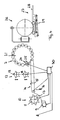
- the drawn in the figures embodiment of the crop processing machine forms a combination of loader wagon and baler, which is integrated together with a downstream bale wrapping in the loading truck.
- the loading carriage 1 comprises a loading space 2, which in the illustrated embodiment is box-shaped and bounded by upright side walls and a front wall.
- the cargo space 2 rests on a machine frame 3, which is supported by a chassis 4.
- the chassis 4 is biaxial, advantageously the machine frame 3 and the chassis 4 form separate modules, so that different chassis 4 under the machine frame 3, in particular multi-axle trolleys 4 are mounted under the machine frame 3.
- the chassis 4 includes a chassis support frame 5, which may be releasably secured to the machine frame 3, wherein advantageously the chassis support frame 5 is set below the machine frame 3, see.
- FIG. 2 the chassis support frame 5 is set below the machine frame 3, see.
- the chassis 4 is advantageously designed such that its wheels 6 is disposed completely below the cargo space 2 and the machine frame 3 carrying this, wherein advantageously no lateral projection is provided so that the chassis 4 in the covered by the hold 2 track of Loading wagon 1 drives.
- the chassis 4 is centrally located under the loading space 2, in particular approximately below the baling device 7 to be described.
- the loader wagon 1 can be attached via a drawbar 8 to a tractor not specifically shown.
- the loading wagon 1 comprises a collecting device 9 in the form of a liftable and lowerable trained pick-up with a rotatably driven spiked roller.
- a loading space filling conveyor 10 Downstream of the collecting device 9 is a loading space filling conveyor 10, which advantageously has a rotatably drivable conveying rotor 11 with cantilevered conveying tines can, who takes over the picked up by the collecting device 9 crop and promotes into the hold 2.
- the loading space Be Colell themeer 10 is advantageously a cutting device 12 preferably in the form of a knife bar, which extends across the loader wagon 1, assigned, the knife protrude into the conveyor channel 13 and there cooperate with the conveyor rotor 11.
- the cutting device 12 is formed extendable out of the conveying channel 13, in particular swung out and / or extendable below the loading space 2, whereby the cutting device 12 is easily accessible.
- a cargo space bottom conveyor 14 is provided at the bottom thereof, which is formed in the illustrated embodiment as a scraper floor 15, through which a through the loading space Befeldll componenter 10 in the hold 2 building Erntegutstock can be conveyed backwards, especially on the baling device 7 too.
- the bottom of the cargo space 2 and the cargo floor conveyor 14 is formed lowerable at its front end by a suitable lifting device, for example in the form of hydraulic cylinders, such that in the lowered position of the cargo compartment floor at the front end of an outlet through which the cargo space 2 can be emptied.
- a suitable lifting device for example in the form of hydraulic cylinders, such that in the lowered position of the cargo compartment floor at the front end of an outlet through which the cargo space 2 can be emptied.
- the not shown scraper floor drive is reversible, so that the scraper floor 15 is driven in the opposite direction, which stored in the hold 2 crop can be unloaded forward.
- the cargo floor conveyor 14 may be pivotally suspended at its lying on the baling device 7 end.
- a metering conveyor 17 is still arranged in front of the baling device 7 in the cargo space 2, wherein in the illustrated embodiment, the metering conveyor 17 has a pair of horizontally disposed, extending transversely over the hold 2 conveyor rollers 18 with projecting conveyor tines.
- These conveyor rollers 18 can advantageously be mounted on the side walls of the cargo space 2 and / or associated holding devices be.
- the conveyor rollers 18 are mounted variable in height and in their distance from each other, for adjusting the desired position and the desired distance from each other corresponding adjusting means are provided, for example in the form of hydraulic cylinders, wherein the conveyor rollers 18 may be mounted in corresponding sliding guides.
- the conveyor rollers 18 can in principle be rotationally driven in the same direction, wherein in an embodiment of the invention, an opposite drive direction can be provided.
- the conveyor roller drive which is not specifically illustrated, can be changed with regard to its drive speed in order to be able to correspondingly change the conveying speed and quantity of the dosing conveyor 17.
- the baling device 7 arranged downstream of the dosing conveyor 17 comprises a frame-fixed front housing 19 and a rear housing 20 which can be pivoted about an upper axis into an unloading position for a round bale, wherein in the closed working position shown, the two press housing parts define an approximately circular cylinder.
- the limited by the two housing parts 19 and 20 pressing space 21 is enclosed by stationary, but rotatably mounted rollers 22, which act as pressing and conveying elements and form a Erntegutballen in a conventional manner.
- the pressing space 21 comprises at its front, lower portion a slot-shaped inlet 23, which is arranged in the region of the rear end of the scraper floor 15.
- feed conveyor 24 is arranged, which is formed in the illustrated embodiment by a horizontally disposed, with its axis of rotation parallel to the axes of the rollers 22 extending conveyor rotor 25 with projecting conveyor tines.
- a bale wrapping device 26 is further arranged in the loading space 2, which is in turn arranged downstream of a Ballenabsch- or -ablagevorraum 27.
- This bale storage device 27 comprises a storage table 28, by a Hubschwenkvortechnik 29 on the one hand between one in FIG. 4 Bale takeover position shown approximately at the level of Balleneinwickelvorides 26 to the ground down into a storage position can be lowered.
- the storage table 28 is advantageously from the horizontal working position, the FIG. 4 shows, in a non-specifically shown in the figures upright transport position pivotally, in which the storage table 28, the rear wall of the loading wagon 1 and the loading space 2 forms.
- FIG. 4 clarifies the collecting device 9, the cargo space Be Colell identifyer 10, the cargo conveyor bottom conveyor 14 and the baling conveyor 17 are controlled by a central control device 30, which varies the respective conveying speeds of the individual conveyor in dependence on the operating parameters described above, and in particular such controls that the baling device operates in a desired power range and / or the loader wagon is driven at a maximum speed.
- a central control device 30 which varies the respective conveying speeds of the individual conveyor in dependence on the operating parameters described above, and in particular such controls that the baling device operates in a desired power range and / or the loader wagon is driven at a maximum speed.
- the baler This allows a continuous operation of the baler can be achieved.
- the crop conveyed by the picking device 9 and the loading space filling conveyor 10 into the loading space 2 is transported back to the baling device 7 by the loading space bottom conveyor 14.
- the press room feed conveyor 24 Through the press room feed conveyor 24, the crop passes through the inlet 23 into the press room 21, where it is formed into a bale. If the baling chamber 21 is full or the bale is pressed, the loading floor conveyor 14 and / or the dosing conveyor 17 and / or the baling chamber feed conveyor 24 are stopped, so that the baling chamber 21 can be opened and the bale transferred to the bale wrapping apparatus 26. During this period, the loader wagon continues with preferably almost undiminished speed.
- the reaching into the hold 2 crop is accumulated in front of the metering conveyor 17 in the hold 2. If the bale is transferred to the bale wrapping device 26, the pressing space 21 is closed again and the bale pressing device 7 is again receptive, the dosing conveyor 17 is put into operation to reduce the dammed Erntegutberg.
Landscapes
- Life Sciences & Earth Sciences (AREA)
- Environmental Sciences (AREA)
- Storage Of Harvested Produce (AREA)
- Harvester Elements (AREA)
- Sanitary Device For Flush Toilet (AREA)
- Fertilizers (AREA)
Abstract
Description
Die vorliegende Erfindung betrifft eine kontinuierlich arbeitende Ballenpresse für landwirtschaftliches Erntegut, mit einem Laderaum, einer Aufsammelvorrichtung zum Aufsammeln von auf dem Boden liegenden Erntegut, einem Laderaum-Befüllförderer zur Beförderung des aufgesammelten Ernteguts in den Laderaum sowie einem Laderaum-Bodenförderer zur Beförderung des Ernteguts im Laderaum weg von dem Befüllförderer, sowie mit einer Ballenpressvorrichtung, die in dem Laderaum des Ladewagens angeordnet ist und einen am Einlass ihres Pressraums angeordneten Pressraum-Beschickungsförderer aufweist, dem durch den Laderaum-Bodenförderer Erntegut zuführbar ist.The present invention relates to a continuous agricultural crop baler having a loading space, a picking device for picking up crops lying on the ground, a loading space filling conveyor for conveying the collected crop to the loading space, and a load floor conveyor for transporting the crop in the loading space away from the Befüllförderer, as well as with a baling device, which is arranged in the loading space of the loading wagon and having a arranged at the inlet of its press room baling chamber feed conveyor, which can be supplied by the loading space bottom conveyor crop.
Eine kontinuierlich arbeitende Ballenpresse zeigt die
Um einen störungsfreien Pressenbetrieb mit möglichst hoher Volumenleistung zu erreichen, sollte ungeachtet des sich im Laderaum aufbauenden Erntegutberges der Ballenpressvorrichtung ein möglichst gleichmäßiger, kontinuierlicher Erntegutstrom zugeführt werden. Die
Hiervon ausgehend liegt der vorliegenden Erfindung die Aufgabe zugrunde, eine verbesserte kontinuierlich arbeitende Ballenpresse zu schaffen, die Nachteile des Standes der Technik vermeidet und letzteren in vorteilhafter Weise weiterbildet. Vorzugsweise soll die Auslastung der Ballenpressvorrichtung durch Ausmerzung von Beschickungsproblemen verbessert und dadurch die Flächenleistung der Ballenpresse weiter erhöht werden.On this basis, the present invention seeks to provide an improved continuously operating baler, which avoids the disadvantages of the prior art and the latter develops advantageously. Preferably, the utilization of the baling device is to be improved by eliminating feed problems, thereby further increasing the area performance of the baler.
Erfindungsgemäß wird diese Aufgabe durch eine kontinuierlich arbeitende Ballenpresse gemäß Anspruch 1 gelöst. Bevorzugte Ausgestaltungen der Erfindung sind Gegenstand der abhängigen Ansprüche.According to the invention, this object is achieved by a continuous baling press according to claim 1. Preferred embodiments of the invention are the subject of the dependent claims.
Die vorliegende Erfindung geht von der Überlegung aus, dass der vor der Ballenpressvorrichtung liegende Laderaum stärker ausgenutzt und auch das Auftürmen größerer Erntegutmengen in diesem Laderaum zugelassen wird, um eine möglichst starke Pufferung zu erreichen und dadurch ein Durchfahren mit möglichst unverminderter Geschwindigkeit auch dann zu ermöglichen, wenn die Ballenpresse insbesondere bei Fertigstellung und Abladung eines Ballens nicht aufnahmebereit ist. Um trotz höherer Erntegutmengen im Laderaum Verstopfungsprobleme bei der Ballenpressvorrichtung zu verhindern, wird eine zusätzliche Vergleichmäßigung des Erntegutstroms beim Abbau eines im als Puffer dienenden Laderaum aufgehäuften Erntegutbergs über den Laderaum-Bodenförderer hinaus vorgesehen. Erfindungsgemäß ist in dem Laderaum des Ladewagens oberhalb des Laderaum-Bodenförderers zwischen dem Laderaum-Befüllförderer und dem Pressraum-Beschickungsförderer ein Dosierförderer zur Dosierung der dem Pressraum zugeführten Erntegutmenge vorgesehen. Dieser zusätzliche Dosierförderer oberhalb des Laderaumbodenförderers ermöglicht gerade bei großen im Laderaum aufgehäuften Erntegutmengen einerseits einen raschen Abbau dieses Erntegutberges und andererseits dennoch eine gleichmäßige Beschickung des Pressraums der Ballenpressvorrichtung ohne die Gefahr von Verstopfungen.The present invention is based on the consideration that the loading space located in front of the baling device is utilized to a greater extent and also the thawing of larger quantities of crops in this loading space is permitted in order to achieve the greatest possible buffering and thereby also to allow passage with as little speed as possible, if the baling press is not ready to receive, especially when finishing and unloading a bale. In order to prevent clogging problems in the baling device despite higher Erntegutmengen in the load compartment, an additional equalization of Erntegutstroms is provided for the dismantling of a serving as a buffer loading space Erntegutbergs on the cargo floor conveyor out. According to the invention, a metering conveyor for metering the crop volume supplied to the pressing space is provided in the loading space of the loading wagon above the loading space bottom conveyor between the loading space filling conveyor and the pressing space loading conveyor. This additional metering conveyor above the load floor conveyor allows just for large amounts of material accumulated in the hold crops on the one hand rapid dismantling of Erntegutberg and on the other hand, a uniform loading of the baling chamber of the baling without the risk of blockages.
Auch wenn der Dosierförderer grundsätzlich verschieden ausgebildet sein kann, umfasst der Dosierförderer in vorteilhafter Weiterbildung der Erfindung mindestens einen rotatorisch antreibbaren Förderrotor, wobei zur Steigerung der Effizienz und der Genauigkeit der Dosierung vorteilhafterweise mindestens ein Paar Förderrotoren vorgesehen sind, die gegenläufig antreibbarer sein können oder alternativ auch gleichsinnig angetrieben werden können. Diese Förderrotoren erstrecken sich vorteilhafterweise deutlich oberhalb des Laderaumbodens, so dass sie vor der Ballenpressvorrichtung sozusagen eine Erntegutbarriere bilden, die bei Abschaltung oder nur langsamem Betrieb der Förderrotoren ein hohes Anhäufen von Erntegut im Laderaum ermöglichen und andererseits ein dosiertes Abfördern und Zufördern zu dem Pressraum auch bei großen gespeicherten Erntegutmengen ermöglichen. Grundsätzlich könnten diese Förderrotoren aufrecht angeordnet sein, so wie dies von Miststreuern bekannt ist. Vorzugsweise jedoch sind die Förderrotoren liegend angeordnet, wobei sie sich vorteilhafterweise quer über den gesamten Laderaum hinweg erstrecken und beispielsweise an den Seitenwänden des Laderaums angelenkt sein können.Even if the metering conveyor can be designed basically different, the metering conveyor in an advantageous embodiment of the invention comprises at least one rotatably driven conveyor rotor, wherein for increasing the efficiency and the accuracy of the dosage advantageously at least a pair of conveyor rotors are provided, which can be driven in opposite directions or alternatively can be driven in the same direction. These conveyor rotors advantageously extend well above the load compartment floor, so that they form a Erntegutbarriere before the baling device, which allow a high accumulation of crops in the hold when switching off or only slow operation of the conveyor rotors and on the other hand a metered discharge and Zufördern to the baling chamber also at enable large quantities of stored crops. In principle, these conveyor rotors could be arranged upright, as known from manure spreaders. Preferably, however, the conveyor rotors are arranged horizontally, wherein they advantageously extend across the entire cargo space and can be articulated, for example, on the side walls of the cargo space.
Zwischen einer Unterkante bzw. Unterseite des Dosierförderers und dem Laderaum-Bodenförderer ist hierbei vorteilhafterweise ein ausreichender Abstand vorgesehen, so dass ein auf dem Laderaumboden laufender Erntegutteppich eingriffsfrei an den Dosierförderern vorbei zur Ballenpressvorrichtung gefördert werden kann. Dies erlaubt es im Normalbetrieb, wenn kein Erntegutberg im Laderaum angehäuft ist, auch ohne Zutun bzw. bei stillstehenden Förderrotoren des Dosierförderers die Ballenpressvorrichtung mit Erntegut zu beschicken, das durch den Laderaum-Bodenförderer zu dem Pressraum befördert werden kann. Durch diesen Abstand der unteren Förderwalze des Dosierförderers vom Laderaumboden kann sozusagen eine Grundbeschickung der Ballenpressvorrichtung erreicht werden.Between a lower edge or underside of the metering conveyor and the loading space floor conveyor, a sufficient distance is advantageously provided, so that a crop carpet running on the load floor can be conveyed without interference to the metering conveyors past the baling device. This allows it in normal operation, if no Erntegutberg is accumulated in the hold, even without any action or in stationary conveyor rotors of the metering conveyor to feed the baling device with crop, which can be transported through the cargo floor conveyor to the baling chamber. By this distance of the lower conveyor roller of the metering conveyor from the load compartment floor can be achieved so to speak, a base load of the baling device.
In Weiterbildung der Erfindung ist der Dosierförderer hinsichtlich seiner Fördermenge variabel einstellbar ausgebildet, und zwar vorteilhafterweise unabhängig von der Fördergeschwindigkeit bzw. der Fördermenge der anderen Förderer des Ladewagens bzw. der Ballenpressvorrichtung. Hierdurch kann der Dosierförderer beispielsweise vorübergehend eine größere Fördermenge nach Auflaufen eines höheren Erntegutberges im Laderaum abfördern, ohne dass der Pressraum-Beschickungsförderer oder der Laderaum-Hüllförderer gleichfalls schneller laufen müsste. Selbstverständlich ist es vorteilhafterweise dabei auch möglich, den Dosierförderer zusammen mit den genannten anderen Förderern in seiner Fördermenge zu verstellen.In a further development of the invention, the dosing conveyor is designed to be variably adjustable in terms of its delivery, advantageously independently of the conveying speed or the delivery rate of the other conveyor of the loading wagon or the baling device. As a result, the dosing conveyor, for example, temporarily convey a larger flow rate after emergence of a higher Erntegutberg in the hold, without the baling chamber feed conveyor or the cargo space Envelope would also have to run faster. Of course, it is advantageously also possible to adjust the metering conveyor together with the other conveyors mentioned in its flow rate.
Die Einstellung der Fördermenge des Dosierförderers kann dabei grundsätzlich auf verschiedene Art und Weise erfolgen. Nach einer bevorzugten Ausführung der Erfindung kann der Dosierförderer eine Einstellvorrichtung zur Veränderung des Abstandes der Förderrotoren voneinander aufweisen. So kann beispielsweise der Abstand der Förderrotoren verkleinert und damit der Durchgang zwischen den beiden Förderrotoren verkleinert werden, um eine geringere Menge zu fördern, bzw. umgekehrt vergrößert werden, um eine größere Fördermenge zu fördern. Auch ist es möglich, mittels der Einstellvorrichtung die Höhe der Förderrotoren über dem Laderaumboden und hierdurch den unter dem Dosierförderer hindurch laufenden Erntegutteppich zu verändern.The adjustment of the delivery rate of the metering conveyor can basically be done in various ways. According to a preferred embodiment of the invention, the metering conveyor may have an adjustment device for changing the distance of the conveyor rotors from each other. Thus, for example, reduces the distance between the conveyor rotors and thus the passage between the two conveyor rotors are reduced in order to promote a smaller amount, or be increased inversely to promote a larger flow rate. It is also possible to change the height of the conveyor rotors above the load compartment floor and thus the crop carpet running underneath the dosing conveyor by means of the adjusting device.
Alternativ oder zusätzlich kann der Dosierförderer Einstellmittel zur Veränderung der Drehgeschwindigkeit der Förderrotoren besitzen, um hierdurch entsprechend die Fördermenge bzw. -leistung zu verändern.Alternatively or additionally, the dosing conveyor may have adjusting means for varying the rotational speed of the conveyor rotors, thereby correspondingly changing the delivery rate or output.
Vorteilhafterweise ist hierbei eine Steuereinrichtung vorgesehen, die die Fördermenge bzw. -leistung des Dosierförderers in Abhängigkeit diverser Betriebsparameter automatisch steuert. Insbesondere kann die Steuereinrichtung hierbei den Belastungs- und/oder Füllzustand der Ballenpressvorrichtung berücksichtigen, insbesondere die Fördermenge des Dosierförderers erhöhen, solange die Ballenpressvorrichtung hinsichtlich ihres Belastungszustandes unter ihrer Maximalbelastung bleibt bzw. kann die Fördermenge des Dosierförderers begrenzt bzw. abgesenkt werden, wenn die Ballenpressvorrichtung ihre Leistungsgrenze erreicht. Vorteilhafterweise wird hierbei die Fördermenge des Dosierförderers in Abhängigkeit des Belastungs- bzw. Füllzustandes der Ballenpressvorrichtung derart geregelt, dass die Ballenpressvorrichtung in einem gewünschten, insbesondere maximalen Leistungsbereich fährt. In Weiterbildung der Erfindung kann die Fördermenge des Dosierförderers dabei nicht nur den Belastungszustand der Ballenpressvorrichtung, sondern auch deren grundsätzlichen Betriebszustand berücksichtigen, insbesondere kann dann die Fördermenge des Dosierförderers heruntergefahren werden, wenn die Ballenpressvorrichtung dabei ist, einen Ballen fertig zu stellen und auszugeben.Advantageously, in this case a control device is provided which automatically controls the delivery rate or performance of the metering conveyor in dependence on various operating parameters. In particular, the control device hereby take into account the loading and / or filling state of the baling device, in particular increase the delivery rate of the dosing conveyor, as long as the baling device remains under its maximum load with respect to their load condition or the delivery of the dosing conveyor can be limited or lowered when the baling their Performance limit reached. Advantageously, in this case the delivery rate of the metering conveyor in dependence the loading or filling state of the baling device regulated such that the baling device moves in a desired, in particular maximum power range. In a further development of the invention, the delivery rate of the dosing conveyor can take into account not only the load condition of the baling device, but also their basic operating condition, in particular then the delivery of the dosing conveyor can be shut down when the baling device is about to finish a bale and spend.
Der Belastungszustand der Ballenpressvorrichtung kann hierbei grundsätzlich in verschiedener Weise erfasst werden, beispielsweise durch Erfassung des Belastungszustandes der den Pressraum begrenzenden Presswalzen. In Weiterbildung der Erfindung kann der Belastungszustand auch über das am Pressraum-Beschickungsförderer vorliegende Drehmoment bzw. dessen Belastungszustand erfasst werden. Die Steuereinrichtung ist hierzu mit einem geeigneten Sensor bzw. einer geeigneten Erfassungsvorrichtung verbunden, die den Betriebs-, Belastungs- und/oder Füllzustand der Ballenpressvorrichtung bestimmt.The load condition of the baling device can in principle be detected in various ways, for example by detecting the load condition of the press room limiting press rollers. In a further development of the invention, the load state can also be detected via the torque present on the press room feed conveyor or its load state. For this purpose, the control device is connected to a suitable sensor or a suitable detection device which determines the operating, loading and / or filling state of the baling device.
Die Fördermenge des Dosierförderers kann weiterhin in vorteilhafter Weiterbildung der Erfindung alternativ oder zusätzlich auch in Abhängigkeit des Laderaum-Befüllzustandes und/oder eines Belastungszustandes des Laderaum-Befüllförderers gesteuert werden. Baut sich beispielsweise am Laderaumbefüllförderer ein zu großer Rückstaudruck auf, kann der Dosierförderer hinsichtlich seiner Fördermenge bzw. -geschwindigkeit nach oben gefahren werden, um diesen Rückstaudruck zu verringern, wobei vorzugsweise dies im Rahmen der der Ballenpressvorrichtung maximal zuführbaren Erntegutmenge erfolgt.The delivery rate of the metering conveyor can also be controlled in an advantageous development of the invention alternatively or additionally also as a function of the loading space filling state and / or a load state of the loading space Befüllförderers. If, for example, an excessive backpressure pressure builds up on the loading space filling conveyor, the dosing conveyor can be moved upwards with regard to its delivery rate or speed in order to reduce this back pressure, wherein this is preferably done within the maximum amount of crop material that can be fed to the baling device.
In Weiterbildung der Erfindung ist nicht nur der Dosierförderer hinsichtlich seiner Fördermenge bzw. Förderleistung variabel steuerbar. Alternativ oder zusätzlich hierzu kann in Weiterbildung der Erfindung die Fördergeschwindigkeit des Laderaum-Bodenförderers durch eine entsprechende Steuereinrichtung in Abhängigkeit eines Belastungs- und/oder Füllzustands der Ballenpressvorrichtung verändert werden. Vorteilhafterweise erfolgt auch hier eine Regelung der Fördergeschwindigkeit des Laderaum-Bodenförderers dahingehend, dass die Ballenpressvorrichtung in einem gewünschten, insbesondere in einem möglichst hohen Leistungsbereich arbeitet und der Ballenpressvorrichtung die entsprechende Erntegutmenge zugeführt wird.In a further development of the invention, not only the metering conveyor is variably controllable with regard to its delivery rate or delivery rate. Alternatively or additionally, in a development of the invention, the conveying speed of the loading floor conveyor can be changed by a corresponding control device as a function of a loading and / or filling state of the baling device become. Advantageously, here too a control of the conveying speed of the loading floor conveyor to the effect that the baling device operates in a desired, in particular in the highest possible power range and the baler device, the corresponding Erntegutmenge is supplied.
Alternativ oder zusätzlich kann die Steuereinrichtung die Fördergeschwindigkeit bzw. -leistung des Laderaum-Bodenförderers und/oder des Dosierförderers und/oder des Pressraum-Beschickungsförderers und/oder des Laderaum-Befüllförderers in Abhängigkeit der Fahrgeschwindigkeit variieren. Hinsichtlich der Fördergeschwindigkeit des Laderaum-Bodenförderers und/oder des Dosierförderers wird dabei insbesondere auch der Belastungszustand des Laderaum-Beschickungsförderers und/oder der Füllzustand des Laderaums berücksichtigt, wobei diese Parameter durch geeignete Erfassungseinrichtungen vorzugsweise in Form von Sensoren bestimmt werden können, wobei beispielsweise die Leistungsaufnahme und/oder das Drehmoment des Laderaum-Befüllförderers erfasst werden kann.Alternatively or additionally, the control device may vary the conveying speed or performance of the loading space bottom conveyor and / or the metering conveyor and / or the baling chamber feed conveyor and / or the loading space filling conveyor depending on the driving speed. With regard to the conveying speed of the loading space floor conveyor and / or the dosing conveyor, the loading state of the loading space loading conveyor and / or the filling state of the loading space is also taken into account, whereby these parameters can be determined by suitable detection devices, preferably in the form of sensors, wherein, for example, the power consumption and / or the torque of the loading space Befüllförderers can be detected.
Um eine möglichst optimale Auslastung der Ballenpresse und damit eine höchstmögliche Flächenleistung, insbesondere der Ballenpressvorrichtung, zu erreichen, kann in Weiterbildung der Erfindung die Steuereinrichtung ein Fahrgeschwindigkeits-Sollwertsignal vorgeben, anhand dessen beispielsweise bei Anzeige dieses Fahrgeschwindigkeits-Sollwertsignals der Fahrer entsprechend eingreifen kann oder vorzugsweise die Fahrgeschwindigkeit automatisch gesteuert werden kann. Dieses Fahrgeschwindigkeits-Sollwertsignal wird dabei vorteilhafterweise in Abhängigkeit des Belastungs-, Betriebs- und/oder Füllzustands der Ballenpressvorrichtung von der Steuereinrichtung bestimmt, wobei die Steuereinrichtung auch noch weitere Parameter, wie beispielsweise den Füllzustand des Laderaums und/oder die Belastung des Laderaumbefüllförderers, berücksichtigen kann.In order to achieve the best possible utilization of the baler and thus the highest possible area performance, in particular the baling device, the control device can specify a driving speed setpoint signal in the invention, on the basis of which, for example, when displaying this vehicle speed setpoint signal, the driver can intervene or preferably the Driving speed can be controlled automatically. This vehicle speed setpoint signal is advantageously determined by the control device as a function of the loading, operating and / or filling state of the baling device, wherein the control device can also take into account further parameters such as the filling state of the cargo space and / or the loading of the loading space filling conveyor ,
In Weiterbildung der Erfindung kann dabei vorteilhafterweise eine Überwachung des Belastungszustandes der Ballenpressvorrichtung erfolgen und das Fahrgeschwindigkeits-Sollwertsignal solange erhöht werden, bis eine maximale Auslastung der Ballenpressvorrichtung erreicht wird. Hierbei kann gleichzeitig eine Begrenzung des Fahrgeschwindigkeits-Sollwertsignals in Abhängigkeit weiterer Betriebsparameter vorgesehen sein, insbesondere in Abhängigkeit des Belastungszustandes der Aufsammeleinrichtung, des Laderaum-Befüllförderers, des Laderaum-Befüllzustandes und/oder des Belastungszustandes des Dosierförderers und/oder des Laderaum-Bodenförderers. Hierbei ist die Steuerung vorteilhafterweise derart ausgebildet, dass immer dann eine Begrenzung des Fahrgeschwindigkeits-Sollwertsignals vorgenommen wird, wenn eine dieser Gerätekomponenten an ihre Leistungsgrenzen kommt.In a further development of the invention can advantageously be carried out a monitoring of the load condition of the baling device and the vehicle speed setpoint signal be increased until a maximum utilization of the baling device is achieved. In this case, at the same time a limitation of the vehicle speed setpoint signal as a function of further operating parameters may be provided, in particular depending on the load condition of the collecting device, the loading space Befüllförderers, the loading space Befüllzustandes and / or the load state of the metering conveyor and / or the load floor conveyor. Here, the control is advantageously designed such that always a limitation of the vehicle speed setpoint signal is made when one of these device components comes to their performance limits.
Um eine möglichst gleichmäßige Beschickung der Ballenpressvorrichtung mit Erntegut zu erreichen, ist in Weiterbildung der Erfindung der Laderaum-Bodenförderer vorteilhafterweise als Kratzbodenförderer ausgebildet. Alternativ zu einem solchen Kratzboden könnte der Laderaum-Bodenförderer auch ein Bandförderer sein. Das Vorsehen eines Kratzbodenförderers kann jedoch hinsichtlich Robustheit und Standfestigkeit Vorteile haben.In order to achieve the most uniform possible loading of the baling device with crop, the load compartment floor conveyor is advantageously designed as a scraper floor conveyor in development of the invention. As an alternative to such a scraper floor, the cargo floor conveyor could also be a belt conveyor. However, the provision of a scraper floor conveyor can have advantages in terms of robustness and stability.
Um ein einfaches Entleeren des Laderaums des Ladewagens zu ermöglichen, ist in Weiterbildung der Erfindung der Laderaumboden zusammen mit dem Laderaum-Bodenförderer an einem der Ballenpressvorrichtung abgewandten Ende, insbesondere also an einem vorderen Ende, absenkbar ausgebildet, wobei der Laderaum-Bodenförderer vorteilhafterweise in seiner Förderrichtung umkehrbar ausgebildet ist, so dass bei abgesenktem Laderaumboden der Laderaum von der Ballenpressvorrichtung weg entladen werden kann.In order to enable a simple emptying of the loading space of the loading wagon, the load compartment floor is formed in a development of the invention, together with the loading space floor conveyor at one end facing away from the baling device, in particular at a front end, lowered, wherein the load floor conveyor advantageously in its conveying direction is formed reversible, so that when the load compartment floor is lowered, the cargo space can be unloaded away from the baling device.
Um eine gleichmäßigere Beschickung der Ballenpressvorrichtung mit Erntegut zu ermöglichen, ist in Weiterbildung der Erfindung dem Laderaum-Befüllförderer ein Schneidwerk zugeordnet, so dass das Erntegut bereits beim Eintritt in den Laderaum entsprechend zerkleinert werden kann, wodurch sich das Erntegut im Laderaum besser verteilt und gleichmäßiger der Ballenpressvorrichtung zugeführt werden kann. Insbesondere kann hierdurch an der Ballenpressvorrichtung selbst auf ein Schneidwerk verzichtet werden bzw. nur ein kleineres Hilfsschneidwerk mit geringerer Schneidleistung und entsprechend weiteren Messerabständen vorgesehen werden, wodurch eine höhere Ballenpressleistung gefahren werden kann. Alternativ kann dem Pressraum-Beschickungsförderer auch ein Schneidwerk höherer Schneidleistung zugeordnet sein, wodurch eine besonders hohe Zerkleinerung des Ernteguts erreicht werden könnte. Bevorzugt ist jedoch die zuvor beschriebene Ausführung, durch die eine höhere Pressleistung bei futterschonender Verarbeitung erreicht werden kann.In order to allow a more uniform loading of the baling device with crop, a deck is associated with the loading space Befüllförderer in development of the invention, so that the crop can be shredded as soon as entering the hold, whereby the crop better distributed in the hold and more uniform Baler can be supplied. In particular, this may be due to the baling device itself a cutting unit are dispensed with or only a smaller auxiliary cutting unit with a lower cutting performance and according to other blade intervals are provided, whereby a higher baling capacity can be driven. Alternatively, the press room feeding conveyor can also be assigned a cutting unit of higher cutting capacity, whereby a particularly high size reduction of the crop could be achieved. Preferably, however, the embodiment described above, by which a higher press performance can be achieved with feed-friendly processing.
Das Schneidwerk, das dem Laderaum-Befüllförderer zugeordnet ist, ist dabei vorteilhafterweise in einfacher Weise zugänglich. In Weiterbildung der Erfindung ist dieses Schneidwerk außerhalb des Laderaums in eine inaktive Stellung und/oder in eine Wartungsstellung aus dem Wirkungsbereich des Laderaum-Befüllförderers ausfahrbar.The cutting mechanism, which is associated with the loading space Befüllförderer, is advantageously accessible in a simple manner. In a development of the invention, this cutting mechanism can be moved out of the loading space into an inactive position and / or into a maintenance position out of the effective range of the loading space filling conveyor.
Um eine möglichst geringe Spurbreite zu erreichen, ist nach einem weiteren vorteilhaften Aspekt der vorliegenden Erfindung der Ladewagen mit einem Fahrwerk versehen, dessen Reifen vollständig unterhalb des Laderaumbodens angeordnet sind. Insbesondere können die Reifen des Fahrwerks vollständig überstandsfrei unter dem Laderaum angeordnet sein und/oder innerhalb der Aufnahmebreite der Aufsammeleinrichtung angeordnet sein. Hierdurch wird auch bei nicht geschwadetem Erntegut kein auf dem Boden liegendes Erntegut überfahren, das erst beim Aufsammeln in der nächsten Fahrgasse aufgenommen wird. Hierdurch kann die Erntegutaufnahme weiter vergleichmäßigt und sich ergebende Beschickungsprobleme bei der Erntegutbeschickung der Ballenpressvorrichtung vermieden werden.In order to achieve the smallest possible track width, according to a further advantageous aspect of the present invention, the loader wagon is provided with a chassis whose tires are arranged completely below the load compartment floor. In particular, the tires of the chassis can be arranged completely supernatant under the load compartment and / or be arranged within the receiving width of the collecting device. As a result, no lying on the ground crop is overrun even when not sweaty crop, which is taken up only when collecting in the next tram. As a result, the Erntegutaufnahme can be further homogenized and resulting feed problems in the Erntegutpeickung the baling device can be avoided.
Der Ballenpressvorrichtung nachgeordnet kann in Weiterbildung der Erfindung eine Balleneinwickelvorrichtung und/oder eine Ballenausgabeeinrichtung vorgesehen sein. Vorteilhafterweise können diese am Heck des Ladewagens hinter der Ballenpressvorrichtung angeordnet sein.Downstream of the baling device can be provided in a further development of the invention, a bale wrapping and / or a bale dispenser. Advantageously, these can be arranged at the rear of the loading wagon behind the baling device.
Nach einer besonders vorteilhaften Ausführung der Erfindung ist dabei eine Ballenablagevorrichtung zum Ablegen der Ballen auf dem Boden vorgesehen, die aus einer abgesenkten Betriebsstellung in eine angehobene, insbesondere im wesentlichen aufrechte Transportstellung bewegt werden kann, in der die Ballenablagevorrichtung eine Rückwand des Ladewagens bildet. Insbesondere kann die Ballenablagevorrichtung einen anhebbaren und absenkbaren Ablagetisch aufweisen, der in eine aufrechte Transportstellung geschwenkt werden kann, in der er die Rückwand des Ladewagens bildet.According to a particularly advantageous embodiment of the invention, a bale depositing device is provided for depositing the bales on the ground, which can be moved from a lowered operating position into a raised, in particular substantially upright transport position, in which the bale depositing device forms a rear wall of the loading wagon. In particular, the ball storage device may have a liftable and lowerable storage table, which can be pivoted into an upright transport position in which it forms the rear wall of the loading wagon.
Die Erfindung wird nachfolgend anhand eines bevorzugten Ausführungsbeispiels und zugehöriger Zeichnungen näher erläutert. In den Zeichnungen zeigen:
- Fig. 1:
- eine schematische, perspektivische Ansicht einer kontinuierlichen Rundballenpresse mit einem bzw. in Form eines Ladewagens nach einer bevorzugten Ausführung der Erfindung,
- Fig. 2:
- eine schematisierte Seitenansicht der Ballenpresse aus
Fig. 1 , die die in den Laderaum des Ladewagens integrierte Ballenpressvorrichtung, die dieser vorgeschaltete Dosiervorrichtung im Laderaum oberhalb des Laderaum-Bodenförderers und die der Ballenpressvorrichtung nachgeordnete Balleneinwickelvorrichtung zeigt, - Fig. 3:
- eine schematisierte Seitenansicht der Rundballenpresse aus
Fig. 1 nach einer alternativen Ausführungsform, bei der der Laderaum des Ladewagens durch eine in der Seitenwand vorgesehene Laderaumtür zugänglich ist, und - Fig.4:
- eine vereinfachte, schematisierte Darstellung der Fördereinrichtungen der Ballenpresse aus den vorhergehenden Figuren und deren Anordnung zueinander.
- Fig. 1:
- a schematic perspective view of a continuous round baler with or in the form of a loading wagon according to a preferred embodiment of the invention,
- Fig. 2:
- a schematic side view of the baler
Fig. 1 showing the bale pressing device integrated in the load compartment of the loading wagon, the dosing device upstream of this loading device in the loading space above the loading space bottom conveyor and the bale wrapping device downstream of the baling device, - 3:
- a schematic side view of the round baler
Fig. 1 according to an alternative embodiment, in which the loading space of the loading wagon is accessible through a space provided in the side wall cargo door, and - Figure 4:
- a simplified, schematic representation of the conveyors of the baler from the previous figures and their arrangement to each other.
Die in den Figuren gezeichnete Ausführung der Erntegutverarbeitungsmaschine bildet eine Kombination aus Ladewagen und Ballenpresse, die zusammen mit einer nachgeschalteten Balleneinwickelvorrichtung in den Ladwagen integriert ist.The drawn in the figures embodiment of the crop processing machine forms a combination of loader wagon and baler, which is integrated together with a downstream bale wrapping in the loading truck.
Der Ladwagen 1 umfasst einen Laderaum 2, der in der gezeichneten Ausführungsform kastenförmig ausgebildet und von aufrechten Seitenwänden und einer Vorderwand begrenzt ist. Der Laderaum 2 ruht dabei auf einem Maschinenrahmen 3, der von einem Fahrwerk 4 getragen wird. In der gezeichneten Ausführung ist dabei das Fahrwerk 4 zweiachsig ausgebildet, wobei vorteilhafterweise der Maschinenrahmen 3 und das Fahrwerk 4 separate Module bilden, so dass verschiedene Fahrwerke 4 unter dem Maschinenrahmen 3, insbesondere auch mehrachsige Fahrwerke 4 unter dem Maschinenrahmen 3 montierbar sind. Wie
Das Fahrwerk 4 ist dabei vorteilhafterweise derart ausgebildet, dass seine Räder 6 vollständig unterhalb des Laderaums 2 und des diesen tragenden Maschinenrahmens 3 angeordnet ist, wobei vorteilhafterweise auch kein seitlicher Überstand vorgesehen ist, so dass das Fahrwerk 4 in der von dem Laderaum 2 überdeckten Spur des Ladewagens 1 fährt. In der gezeichneten Ausführung ist dabei das Fahrwerk 4 mittig unter dem Laderaum 2, insbesondere etwa unter der noch zu beschreibenden Ballenpressvorrichtung 7 angeordnet.The chassis 4 is advantageously designed such that its
Der Ladewagen 1 ist dabei über eine Deichsel 8 an einen nicht eigens gezeigten Schlepper anhängbar.The loader wagon 1 can be attached via a
Am Bug des Ladewagens 1 bzw. des Laderaums 2 umfasst der Ladewagen 1 eine Aufsammeleinrichtung 9 in Form einer anhebbar und absenkbar ausgebildeten Pick-up mit einer rotatorisch antreibbaren Stachelwalze. Der Aufsammeleinrichtung 9 nachgeordnet ist ein Laderaum-Befüllförderer 10, der vorteilhafterweise einen rotatorisch antreibbaren Förderrotor 11 mit auskragenden Förderzinken aufweisen kann, der das von der Aufsammeleinrichtung 9 aufgenommene Erntegut übernimmt und in den Laderaum 2 fördert. Dem Laderaum-Befüllförderer 10 ist dabei vorteilhafterweise eine Schneidvorrichtung 12 vorzugsweise in Form eines Messerbalkens, der sich quer über den Ladewagen 1 erstreckt, zugeordnet, dessen Messer in den Förderkanal 13 ragen und dort mit dem Förderrotor 11 zusammenwirken. Vorzugsweise ist die Schneidvorrichtung 12 dabei aus dem Förderkanal 13 ausfahrbar ausgebildet, insbesondere unterhalb des Laderaums 2 ausschwenkbar und/oder ausfahrbar, wodurch die Schneidvorrichtung 12 gut zugänglich ist.At the bow of the loading wagon 1 or the
In dem Laderaum 2 ist an dessen Boden ein Laderaum-Bodenförderer 14 vorgesehen, der in der gezeichneten Ausführung als Kratzboden 15 ausgebildet ist, durch den ein sich durch den Laderaum-Befüllförderer 10 im Laderaum 2 aufbauender Erntegutstock nach hinten abförderbar ist, insbesondere auf die Ballenpressvorrichtung 7 zu.In the
Wie in
Oberhalb des Laderaum-Bodenförderers 14 ist in dem Laderaum 2 ein Dosierförderer 17 noch vor der Ballenpressvorrichtung 7 angeordnet, wobei in der gezeichneten Ausführungsform der Dosierförderer 17 ein Paar liegend angeordnete, sich quer über den Laderaum 2 erstreckende Förderwalzen 18 mit abstehenden Förderzinken aufweist. Diese Förderwalzen 18 können vorteilhafterweise an den Seitenwänden des Laderaums 2 und/oder damit verbundenen Halteeinrichtungen gelagert sein. Vorteilhafterweise sind die Förderwalzen 18 in ihrer Höhe und in ihrem Abstand voneinander veränderbar gelagert, wobei zur Einstellung der gewünschten Position und des gewünschten Abstands voneinander entsprechende Stellmittel vorgesehen sind, beispielsweise in Form von Hydraulikzylindern, wobei die Förderwalzen 18 in entsprechenden Schiebeführungen gelagert sein können.Above the
Die Förderwalzen 18 können grundsätzlich gleichsinnig rotatorisch antreibbar sein, wobei in Weiterbildung der Erfindung auch eine gegenläufige Antriebsrichtung vorgesehen sein kann. Der nicht eigens dargestellte Förderwalzenantrieb ist dabei hinsichtlich seiner Antriebsdrehzahl veränderbar, um die Fördergeschwindigkeit und - menge des Dosierförderers 17 entsprechend verändern zu können.The
Die stromab des Dosierförderers 17 angeordnete Ballenpressvorrichtung 7 umfasst ein gestellfestes Vordergehäuse 19 sowie ein relativ hierzu um eine obere Achse in eine Entladestellung für einen Rundballen aufschwenkbares Hintergehäuse 20, wobei in der gezeigten, geschlossenen Arbeitsstellung die beiden Pressengehäuseteile einen etwa kreisförmigen Zylinder definieren. Der von den beiden Gehäuseteilen 19 und 20 begrenzte Pressraum 21 wird dabei von ortsfest, jedoch drehbar gelagerten Walzen 22 umschlossen, die als Press- und Förderelemente wirken und in an sich bekannter Weise einen Erntegutballen formen.The
Der Pressraum 21 umfasst an seinem vorderen, unteren Abschnitt einen schlitzförmigen Einlass 23, der im Bereich des hinteren Endes des Kratzbodens 15 angeordnet ist. Im Bereich dieses Einlasses 23 ist der Pressraum-Beschickungsförderer 24 angeordnet, der in der gezeichneten Ausführungsform durch einen liegend angeordneten, sich mit seiner Drehachse parallel zu den Achsen der Walzen 22 erstreckenden Förderrotor 25 mit abstehenden Förderzinken gebildet wird.The
Hinter der Ballenpressvorrichtung 7 ist in dem Laderaum 2 weiterhin eine Balleneinwickelvorrichtung 26 angeordnet, der wiederum eine Ballenabwurf- bzw. -ablagevorrichtung 27 nachgeordnet ist. Diese Ballenablagevorrichtung 27 umfasst einen Ablagetisch 28, der durch eine Hubschwenkvorrichtung 29 einerseits zwischen einer in
Wie
Hierdurch lässt sich ein kontinuierlicher Betrieb der Ballenpresse erreichen. Im Normalbetrieb wird dabei das von der Aufsammeleinrichtung 9 und dem Laderaum-Befüllförderer 10 in den Laderaum 2 beförderte Erntegut durch den Laderaum-Bodenförderer 14 nach hinten auf die Ballenpressvorrichtung 7 zu transportiert. Durch den Pressraumbeschickungsförderer 24 gelangt das Erntegut durch den Einlass 23 in den Pressraum 21, wo es zu einem Ballen geformt wird. Ist der Pressraum 21 voll bzw. der Ballen gepresst, wird der Laderaum-Bodenförderer 14 und/oder der Dosierförderer 17 und/oder der Pressraumbeschickungsförderer 24 angehalten, so dass der Pressraum 21 geöffnet und der Ballen an die Balleneinwickelvorrichtung 26 übergeben werden kann. Während dieser Zeitspanne fährt der Ladewagen mit vorzugsweise nahezu unverminderter Geschwindigkeit weiter. Das in den Laderaum 2 gelangende Erntegut wird vor dem Dosierförderer 17 in dem Laderaum 2 angehäuft. Ist der Ballen an die Balleneinwickelvorrichtung 26 übergeben, der Pressraum 21 wieder geschlossen und die Ballenpressvorrichtung 7 wieder aufnahmefähig, wird der Dosierförderer 17 in Betrieb gesetzt, um den aufgestauten Erntegutberg abzubauen.This allows a continuous operation of the baler can be achieved. During normal operation, the crop conveyed by the picking
Claims (22)
Applications Claiming Priority (1)
| Application Number | Priority Date | Filing Date | Title |
|---|---|---|---|
| DE102007018329A DE102007018329A1 (en) | 2007-04-18 | 2007-04-18 | Continuous baler |
Publications (2)
| Publication Number | Publication Date |
|---|---|
| EP1982575A1 true EP1982575A1 (en) | 2008-10-22 |
| EP1982575B1 EP1982575B1 (en) | 2010-06-09 |
Family
ID=39471036
Family Applications (1)
| Application Number | Title | Priority Date | Filing Date |
|---|---|---|---|
| EP08003409A Not-in-force EP1982575B1 (en) | 2007-04-18 | 2008-02-25 | Continuously operating baler |
Country Status (3)
| Country | Link |
|---|---|
| EP (1) | EP1982575B1 (en) |
| AT (1) | ATE470347T1 (en) |
| DE (2) | DE102007018329A1 (en) |
Cited By (10)
| Publication number | Priority date | Publication date | Assignee | Title |
|---|---|---|---|---|
| EP2196082A1 (en) * | 2008-12-10 | 2010-06-16 | Lely Patent N.V. | Continuously operating baler |
| WO2011012960A3 (en) * | 2009-07-31 | 2011-04-07 | Agco Corporation | Continuous round baler with pickup |
| WO2011012956A3 (en) * | 2009-07-31 | 2011-04-07 | Agco Corporation | Continuous round baler |
| US8443580B2 (en) | 2009-07-31 | 2013-05-21 | Agco Corporation | Baler pickup for collecting biomass from a combine harvester |
| US8464508B2 (en) | 2009-07-31 | 2013-06-18 | Agco Corporation | Biomass baler |
| US8490375B2 (en) | 2009-07-31 | 2013-07-23 | Agco Corporation | Baler collector for collecting biomass from a combine harvester |
| US20140123616A1 (en) * | 2012-04-05 | 2014-05-08 | Agronic Oy | Baler and Method for Forming a Bale |
| EP2275287B1 (en) * | 2009-07-16 | 2016-01-06 | Alois Pöttinger Maschinenfabrik Ges. m.b.H. | Agricultural machine |
| CN109937714A (en) * | 2019-04-04 | 2019-06-28 | 芜湖苜邦智能装备有限公司 | A kind of circle bale baler equipped with stalk caching room |
| EP3506731A4 (en) * | 2016-08-31 | 2020-05-27 | Vermeer Manufacturing Company | Continuous round baler and improved method of round bale formation |
Families Citing this family (4)
| Publication number | Priority date | Publication date | Assignee | Title |
|---|---|---|---|---|
| DE102011109899B4 (en) * | 2011-08-10 | 2013-02-21 | Maschinenfabrik Bernard Krone Gmbh | Round agricultural baler |
| DE102011109890B4 (en) * | 2011-08-10 | 2013-07-04 | Maschinenfabrik Bernard Krone Gmbh | Round agricultural baler |
| DE202012006091U1 (en) * | 2012-06-22 | 2013-09-24 | Alois Pöttinger Maschinenfabrik Ges.m.b.H. | Agricultural harvester |
| DE102014006179A1 (en) * | 2014-04-29 | 2015-10-29 | Alois Pöttinger Maschinenfabrik Gmbh | harvester |
Citations (4)
| Publication number | Priority date | Publication date | Assignee | Title |
|---|---|---|---|---|
| DE2634638A1 (en) * | 1976-07-31 | 1978-02-02 | Claas Maschf Gmbh Geb | Large dia. bale rolling press - has storage and coiling chambers separated by tiltable endless belt adjacent lower rollers of rolling belt |
| EP0350514A1 (en) * | 1988-07-11 | 1990-01-17 | Maschinenfabrik Bernard Krone GmbH | Round-bale press |
| DE19932336A1 (en) | 1999-07-10 | 2001-01-11 | Lely Welger Maschinenfabrik Gm | Continuously operating agricultural baling press has two conveyors between crop storage chamber and press chamber |
| DE10006384A1 (en) * | 2000-02-12 | 2001-08-16 | Deere & Co | Round baler |
-
2007
- 2007-04-18 DE DE102007018329A patent/DE102007018329A1/en not_active Withdrawn
-
2008
- 2008-02-25 AT AT08003409T patent/ATE470347T1/en active
- 2008-02-25 EP EP08003409A patent/EP1982575B1/en not_active Not-in-force
- 2008-02-25 DE DE502008000757T patent/DE502008000757D1/en active Active
Patent Citations (4)
| Publication number | Priority date | Publication date | Assignee | Title |
|---|---|---|---|---|
| DE2634638A1 (en) * | 1976-07-31 | 1978-02-02 | Claas Maschf Gmbh Geb | Large dia. bale rolling press - has storage and coiling chambers separated by tiltable endless belt adjacent lower rollers of rolling belt |
| EP0350514A1 (en) * | 1988-07-11 | 1990-01-17 | Maschinenfabrik Bernard Krone GmbH | Round-bale press |
| DE19932336A1 (en) | 1999-07-10 | 2001-01-11 | Lely Welger Maschinenfabrik Gm | Continuously operating agricultural baling press has two conveyors between crop storage chamber and press chamber |
| DE10006384A1 (en) * | 2000-02-12 | 2001-08-16 | Deere & Co | Round baler |
Cited By (17)
| Publication number | Priority date | Publication date | Assignee | Title |
|---|---|---|---|---|
| EP2196082A1 (en) * | 2008-12-10 | 2010-06-16 | Lely Patent N.V. | Continuously operating baler |
| EP2275287B1 (en) * | 2009-07-16 | 2016-01-06 | Alois Pöttinger Maschinenfabrik Ges. m.b.H. | Agricultural machine |
| US8464508B2 (en) | 2009-07-31 | 2013-06-18 | Agco Corporation | Biomass baler |
| US8490375B2 (en) | 2009-07-31 | 2013-07-23 | Agco Corporation | Baler collector for collecting biomass from a combine harvester |
| CN102770013A (en) * | 2009-07-31 | 2012-11-07 | 爱科公司 | Continuous round baler |
| CN102781219A (en) * | 2009-07-31 | 2012-11-14 | 爱科公司 | Continuous round baler with pickup |
| US8413414B2 (en) | 2009-07-31 | 2013-04-09 | Agco Corporation | Continuous round baler with accumulation conveyor |
| US8443580B2 (en) | 2009-07-31 | 2013-05-21 | Agco Corporation | Baler pickup for collecting biomass from a combine harvester |
| WO2011012956A3 (en) * | 2009-07-31 | 2011-04-07 | Agco Corporation | Continuous round baler |
| US20120222565A1 (en) * | 2009-07-31 | 2012-09-06 | Agco Corporation | Continuous Round Baler With Pickup |
| US8544243B2 (en) * | 2009-07-31 | 2013-10-01 | Agco Corporation | Method of using an accumulation conveyor with a continuous round baler |
| WO2011012960A3 (en) * | 2009-07-31 | 2011-04-07 | Agco Corporation | Continuous round baler with pickup |
| CN102781219B (en) * | 2009-07-31 | 2015-09-16 | 爱科公司 | There is the continuous circular binder of pick device |
| US20140123616A1 (en) * | 2012-04-05 | 2014-05-08 | Agronic Oy | Baler and Method for Forming a Bale |
| EP3506731A4 (en) * | 2016-08-31 | 2020-05-27 | Vermeer Manufacturing Company | Continuous round baler and improved method of round bale formation |
| US11382275B2 (en) | 2016-08-31 | 2022-07-12 | Tube-Line Manufacturing Limited | Continuous round baler accumulation chamber |
| CN109937714A (en) * | 2019-04-04 | 2019-06-28 | 芜湖苜邦智能装备有限公司 | A kind of circle bale baler equipped with stalk caching room |
Also Published As
| Publication number | Publication date |
|---|---|
| ATE470347T1 (en) | 2010-06-15 |
| DE102007018329A1 (en) | 2008-10-23 |
| EP1982575B1 (en) | 2010-06-09 |
| DE502008000757D1 (en) | 2010-07-22 |
Similar Documents
| Publication | Publication Date | Title |
|---|---|---|
| EP1982575B1 (en) | Continuously operating baler | |
| DE102011109899B4 (en) | Round agricultural baler | |
| EP2196082B1 (en) | Continuously operating baler | |
| EP2067399B1 (en) | Arrangement to adjust the position of a pick-up drum and a pressing element in an agricultural harvesting machine | |
| DE60218400T2 (en) | Round baler | |
| EP2556744B1 (en) | Agricultural round baler | |
| DE19932336A1 (en) | Continuously operating agricultural baling press has two conveyors between crop storage chamber and press chamber | |
| EP2556741B1 (en) | Agricultural baler | |
| EP3747643B1 (en) | Baling press with material feeding device | |
| AT513427B1 (en) | Harvest truck for picking up and transporting plants or parts of plants | |
| DE102011109890B4 (en) | Round agricultural baler | |
| DE102011109893A1 (en) | Continuous agricultural round baler for forming round bales of crop material, has conveying device that is designed as roll and is assigned to storage space in inlet region of pressing chamber | |
| EP1935230B1 (en) | Harvester | |
| DE102011051833B3 (en) | Mixer feeders | |
| EP3771324B1 (en) | Loading and/or schredding carriage | |
| EP3959961B1 (en) | Baler press with removable cutting module and method for handling such a removable cutting module | |
| DE4312991A1 (en) | Process and press for forming cuboid bales from agricultural crops | |
| DE3402959A1 (en) | Elevator | |
| DE2218773C3 (en) | Agricultural trailer with a loading device | |
| DE102022112974A1 (en) | Dosing device for the metered forwarding of loose crops and device for pressing crops | |
| WO1996008133A1 (en) | Self-propelled harvester | |
| DE4216099C1 (en) | Loader for silage into drying container - has reciprocating spreader under discharge point of hoist to layer silage evenly into container. | |
| DE19853920A1 (en) | Selfpropelled forage harvester for remote dumping presses harvested chopped crop up into both container halves prior to removal by wagon to dump or silo site. | |
| DE1582497A1 (en) | Loader wagons with a motorized unloading or dosing device | |
| DE2014184A1 (en) | Screw conveyor for unloading harvest wagons and for loading unloading blowers on forage wagons |
Legal Events
| Date | Code | Title | Description |
|---|---|---|---|
| PUAI | Public reference made under article 153(3) epc to a published international application that has entered the european phase |
Free format text: ORIGINAL CODE: 0009012 |
|
| AK | Designated contracting states |
Kind code of ref document: A1 Designated state(s): AT BE BG CH CY CZ DE DK EE ES FI FR GB GR HR HU IE IS IT LI LT LU LV MC MT NL NO PL PT RO SE SI SK TR |
|
| AX | Request for extension of the european patent |
Extension state: AL BA MK RS |
|
| 17P | Request for examination filed |
Effective date: 20081121 |
|
| AKX | Designation fees paid |
Designated state(s): AT BE BG CH CY CZ DE DK EE ES FI FR GB GR HR HU IE IS IT LI LT LU LV MC MT NL NO PL PT RO SE SI SK TR |
|
| GRAP | Despatch of communication of intention to grant a patent |
Free format text: ORIGINAL CODE: EPIDOSNIGR1 |
|
| GRAS | Grant fee paid |
Free format text: ORIGINAL CODE: EPIDOSNIGR3 |
|
| GRAA | (expected) grant |
Free format text: ORIGINAL CODE: 0009210 |
|
| AK | Designated contracting states |
Kind code of ref document: B1 Designated state(s): AT BE BG CH CY CZ DE DK EE ES FI FR GB GR HR HU IE IS IT LI LT LU LV MC MT NL NO PL PT RO SE SI SK TR |
|
| REG | Reference to a national code |
Ref country code: CH Ref legal event code: EP |
|
| REG | Reference to a national code |
Ref country code: IE Ref legal event code: FG4D Free format text: LANGUAGE OF EP DOCUMENT: GERMAN |
|
| REF | Corresponds to: |
Ref document number: 502008000757 Country of ref document: DE Date of ref document: 20100722 Kind code of ref document: P |
|
| REG | Reference to a national code |
Ref country code: NL Ref legal event code: T3 |
|
| PG25 | Lapsed in a contracting state [announced via postgrant information from national office to epo] |
Ref country code: NO Free format text: LAPSE BECAUSE OF FAILURE TO SUBMIT A TRANSLATION OF THE DESCRIPTION OR TO PAY THE FEE WITHIN THE PRESCRIBED TIME-LIMIT Effective date: 20100909 Ref country code: SE Free format text: LAPSE BECAUSE OF FAILURE TO SUBMIT A TRANSLATION OF THE DESCRIPTION OR TO PAY THE FEE WITHIN THE PRESCRIBED TIME-LIMIT Effective date: 20100609 Ref country code: LT Free format text: LAPSE BECAUSE OF FAILURE TO SUBMIT A TRANSLATION OF THE DESCRIPTION OR TO PAY THE FEE WITHIN THE PRESCRIBED TIME-LIMIT Effective date: 20100609 |
|
| LTIE | Lt: invalidation of european patent or patent extension |
Effective date: 20100609 |
|
| PG25 | Lapsed in a contracting state [announced via postgrant information from national office to epo] |
Ref country code: LV Free format text: LAPSE BECAUSE OF FAILURE TO SUBMIT A TRANSLATION OF THE DESCRIPTION OR TO PAY THE FEE WITHIN THE PRESCRIBED TIME-LIMIT Effective date: 20100609 Ref country code: SI Free format text: LAPSE BECAUSE OF FAILURE TO SUBMIT A TRANSLATION OF THE DESCRIPTION OR TO PAY THE FEE WITHIN THE PRESCRIBED TIME-LIMIT Effective date: 20100609 Ref country code: HR Free format text: LAPSE BECAUSE OF FAILURE TO SUBMIT A TRANSLATION OF THE DESCRIPTION OR TO PAY THE FEE WITHIN THE PRESCRIBED TIME-LIMIT Effective date: 20100609 Ref country code: FI Free format text: LAPSE BECAUSE OF FAILURE TO SUBMIT A TRANSLATION OF THE DESCRIPTION OR TO PAY THE FEE WITHIN THE PRESCRIBED TIME-LIMIT Effective date: 20100609 |
|
| PG25 | Lapsed in a contracting state [announced via postgrant information from national office to epo] |
Ref country code: PL Free format text: LAPSE BECAUSE OF FAILURE TO SUBMIT A TRANSLATION OF THE DESCRIPTION OR TO PAY THE FEE WITHIN THE PRESCRIBED TIME-LIMIT Effective date: 20100609 Ref country code: CY Free format text: LAPSE BECAUSE OF FAILURE TO SUBMIT A TRANSLATION OF THE DESCRIPTION OR TO PAY THE FEE WITHIN THE PRESCRIBED TIME-LIMIT Effective date: 20100609 |
|
| REG | Reference to a national code |
Ref country code: IE Ref legal event code: FD4D |
|
| PG25 | Lapsed in a contracting state [announced via postgrant information from national office to epo] |
Ref country code: IE Free format text: LAPSE BECAUSE OF FAILURE TO SUBMIT A TRANSLATION OF THE DESCRIPTION OR TO PAY THE FEE WITHIN THE PRESCRIBED TIME-LIMIT Effective date: 20100609 Ref country code: EE Free format text: LAPSE BECAUSE OF FAILURE TO SUBMIT A TRANSLATION OF THE DESCRIPTION OR TO PAY THE FEE WITHIN THE PRESCRIBED TIME-LIMIT Effective date: 20100609 |
|
| PG25 | Lapsed in a contracting state [announced via postgrant information from national office to epo] |
Ref country code: RO Free format text: LAPSE BECAUSE OF FAILURE TO SUBMIT A TRANSLATION OF THE DESCRIPTION OR TO PAY THE FEE WITHIN THE PRESCRIBED TIME-LIMIT Effective date: 20100609 Ref country code: CZ Free format text: LAPSE BECAUSE OF FAILURE TO SUBMIT A TRANSLATION OF THE DESCRIPTION OR TO PAY THE FEE WITHIN THE PRESCRIBED TIME-LIMIT Effective date: 20100609 Ref country code: IS Free format text: LAPSE BECAUSE OF FAILURE TO SUBMIT A TRANSLATION OF THE DESCRIPTION OR TO PAY THE FEE WITHIN THE PRESCRIBED TIME-LIMIT Effective date: 20101009 Ref country code: SK Free format text: LAPSE BECAUSE OF FAILURE TO SUBMIT A TRANSLATION OF THE DESCRIPTION OR TO PAY THE FEE WITHIN THE PRESCRIBED TIME-LIMIT Effective date: 20100609 |
|
| PG25 | Lapsed in a contracting state [announced via postgrant information from national office to epo] |
Ref country code: IT Free format text: LAPSE BECAUSE OF FAILURE TO SUBMIT A TRANSLATION OF THE DESCRIPTION OR TO PAY THE FEE WITHIN THE PRESCRIBED TIME-LIMIT Effective date: 20100609 |
|
| PLBE | No opposition filed within time limit |
Free format text: ORIGINAL CODE: 0009261 |
|
| STAA | Information on the status of an ep patent application or granted ep patent |
Free format text: STATUS: NO OPPOSITION FILED WITHIN TIME LIMIT |
|
| PG25 | Lapsed in a contracting state [announced via postgrant information from national office to epo] |
Ref country code: DK Free format text: LAPSE BECAUSE OF FAILURE TO SUBMIT A TRANSLATION OF THE DESCRIPTION OR TO PAY THE FEE WITHIN THE PRESCRIBED TIME-LIMIT Effective date: 20100609 |
|
| PG25 | Lapsed in a contracting state [announced via postgrant information from national office to epo] |
Ref country code: GR Free format text: LAPSE BECAUSE OF FAILURE TO SUBMIT A TRANSLATION OF THE DESCRIPTION OR TO PAY THE FEE WITHIN THE PRESCRIBED TIME-LIMIT Effective date: 20100910 |
|
| REG | Reference to a national code |
Ref country code: DE Ref legal event code: R097 Ref document number: 502008000757 Country of ref document: DE Effective date: 20110309 |
|
| BERE | Be: lapsed |
Owner name: ALOIS POTTINGER MASCHINENFABRIK GES. M.B.H. Effective date: 20110228 |
|
| PG25 | Lapsed in a contracting state [announced via postgrant information from national office to epo] |
Ref country code: MC Free format text: LAPSE BECAUSE OF NON-PAYMENT OF DUE FEES Effective date: 20110228 |
|
| PG25 | Lapsed in a contracting state [announced via postgrant information from national office to epo] |
Ref country code: BE Free format text: LAPSE BECAUSE OF NON-PAYMENT OF DUE FEES Effective date: 20110228 |
|
| PG25 | Lapsed in a contracting state [announced via postgrant information from national office to epo] |
Ref country code: MT Free format text: LAPSE BECAUSE OF FAILURE TO SUBMIT A TRANSLATION OF THE DESCRIPTION OR TO PAY THE FEE WITHIN THE PRESCRIBED TIME-LIMIT Effective date: 20100609 |
|
| REG | Reference to a national code |
Ref country code: CH Ref legal event code: PL |
|
| GBPC | Gb: european patent ceased through non-payment of renewal fee |
Effective date: 20120225 |
|
| PG25 | Lapsed in a contracting state [announced via postgrant information from national office to epo] |
Ref country code: LI Free format text: LAPSE BECAUSE OF NON-PAYMENT OF DUE FEES Effective date: 20120229 Ref country code: CH Free format text: LAPSE BECAUSE OF NON-PAYMENT OF DUE FEES Effective date: 20120229 |
|
| PG25 | Lapsed in a contracting state [announced via postgrant information from national office to epo] |
Ref country code: GB Free format text: LAPSE BECAUSE OF NON-PAYMENT OF DUE FEES Effective date: 20120225 |
|
| PG25 | Lapsed in a contracting state [announced via postgrant information from national office to epo] |
Ref country code: LU Free format text: LAPSE BECAUSE OF NON-PAYMENT OF DUE FEES Effective date: 20110225 |
|
| PG25 | Lapsed in a contracting state [announced via postgrant information from national office to epo] |
Ref country code: PT Free format text: LAPSE BECAUSE OF NON-PAYMENT OF DUE FEES Effective date: 20100609 |
|
| PG25 | Lapsed in a contracting state [announced via postgrant information from national office to epo] |
Ref country code: BG Free format text: LAPSE BECAUSE OF FAILURE TO SUBMIT A TRANSLATION OF THE DESCRIPTION OR TO PAY THE FEE WITHIN THE PRESCRIBED TIME-LIMIT Effective date: 20100909 Ref country code: TR Free format text: LAPSE BECAUSE OF FAILURE TO SUBMIT A TRANSLATION OF THE DESCRIPTION OR TO PAY THE FEE WITHIN THE PRESCRIBED TIME-LIMIT Effective date: 20100609 |
|
| PG25 | Lapsed in a contracting state [announced via postgrant information from national office to epo] |
Ref country code: HU Free format text: LAPSE BECAUSE OF FAILURE TO SUBMIT A TRANSLATION OF THE DESCRIPTION OR TO PAY THE FEE WITHIN THE PRESCRIBED TIME-LIMIT Effective date: 20100609 Ref country code: ES Free format text: LAPSE BECAUSE OF FAILURE TO SUBMIT A TRANSLATION OF THE DESCRIPTION OR TO PAY THE FEE WITHIN THE PRESCRIBED TIME-LIMIT Effective date: 20100920 |
|
| REG | Reference to a national code |
Ref country code: AT Ref legal event code: MM01 Ref document number: 470347 Country of ref document: AT Kind code of ref document: T Effective date: 20130225 |
|
| PG25 | Lapsed in a contracting state [announced via postgrant information from national office to epo] |
Ref country code: AT Free format text: LAPSE BECAUSE OF NON-PAYMENT OF DUE FEES Effective date: 20130225 |
|
| REG | Reference to a national code |
Ref country code: FR Ref legal event code: PLFP Year of fee payment: 9 |
|
| PGFP | Annual fee paid to national office [announced via postgrant information from national office to epo] |
Ref country code: FR Payment date: 20160224 Year of fee payment: 9 Ref country code: NL Payment date: 20160218 Year of fee payment: 9 |
|
| PGFP | Annual fee paid to national office [announced via postgrant information from national office to epo] |
Ref country code: DE Payment date: 20160727 Year of fee payment: 9 |
|
| REG | Reference to a national code |
Ref country code: DE Ref legal event code: R119 Ref document number: 502008000757 Country of ref document: DE |
|
| REG | Reference to a national code |
Ref country code: NL Ref legal event code: MM Effective date: 20170301 |
|
| PG25 | Lapsed in a contracting state [announced via postgrant information from national office to epo] |
Ref country code: NL Free format text: LAPSE BECAUSE OF NON-PAYMENT OF DUE FEES Effective date: 20170301 |
|
| REG | Reference to a national code |
Ref country code: FR Ref legal event code: ST Effective date: 20171031 |
|
| PG25 | Lapsed in a contracting state [announced via postgrant information from national office to epo] |
Ref country code: DE Free format text: LAPSE BECAUSE OF NON-PAYMENT OF DUE FEES Effective date: 20170901 Ref country code: FR Free format text: LAPSE BECAUSE OF NON-PAYMENT OF DUE FEES Effective date: 20170228 |