EP1982573A1 - Landwirtschaftliche Arbeitsmaschine - Google Patents
Landwirtschaftliche Arbeitsmaschine Download PDFInfo
- Publication number
- EP1982573A1 EP1982573A1 EP08101037A EP08101037A EP1982573A1 EP 1982573 A1 EP1982573 A1 EP 1982573A1 EP 08101037 A EP08101037 A EP 08101037A EP 08101037 A EP08101037 A EP 08101037A EP 1982573 A1 EP1982573 A1 EP 1982573A1
- Authority
- EP
- European Patent Office
- Prior art keywords
- conditioning
- gap
- forage harvester
- passage
- crop
- Prior art date
- Legal status (The legal status is an assumption and is not a legal conclusion. Google has not performed a legal analysis and makes no representation as to the accuracy of the status listed.)
- Granted
Links
- 230000003750 conditioning effect Effects 0.000 claims abstract description 112
- 239000004459 forage Substances 0.000 claims description 25
- 230000008859 change Effects 0.000 claims description 9
- 239000000463 material Substances 0.000 claims description 7
- 239000002245 particle Substances 0.000 claims description 6
- 238000001514 detection method Methods 0.000 claims description 3
- 230000003247 decreasing effect Effects 0.000 claims description 2
- 238000011144 upstream manufacturing Methods 0.000 claims description 2
- 238000005549 size reduction Methods 0.000 claims 1
- 230000000694 effects Effects 0.000 description 9
- 230000002093 peripheral effect Effects 0.000 description 8
- 238000011161 development Methods 0.000 description 4
- 230000006978 adaptation Effects 0.000 description 3
- 230000008878 coupling Effects 0.000 description 3
- 238000010168 coupling process Methods 0.000 description 3
- 238000005859 coupling reaction Methods 0.000 description 3
- 238000011156 evaluation Methods 0.000 description 3
- 238000012546 transfer Methods 0.000 description 3
- 230000009471 action Effects 0.000 description 2
- 230000008901 benefit Effects 0.000 description 2
- 230000006835 compression Effects 0.000 description 2
- 238000007906 compression Methods 0.000 description 2
- 230000007423 decrease Effects 0.000 description 2
- 238000006073 displacement reaction Methods 0.000 description 2
- 238000004146 energy storage Methods 0.000 description 2
- 238000000034 method Methods 0.000 description 2
- 238000005457 optimization Methods 0.000 description 2
- 210000000056 organ Anatomy 0.000 description 2
- 230000008569 process Effects 0.000 description 2
- 238000013461 design Methods 0.000 description 1
- 238000005265 energy consumption Methods 0.000 description 1
- 230000007246 mechanism Effects 0.000 description 1
Images

Classifications
-
- A—HUMAN NECESSITIES
- A01—AGRICULTURE; FORESTRY; ANIMAL HUSBANDRY; HUNTING; TRAPPING; FISHING
- A01D—HARVESTING; MOWING
- A01D43/00—Mowers combined with apparatus performing additional operations while mowing
- A01D43/10—Mowers combined with apparatus performing additional operations while mowing with means for crushing or bruising the mown crop
-
- A—HUMAN NECESSITIES
- A01—AGRICULTURE; FORESTRY; ANIMAL HUSBANDRY; HUNTING; TRAPPING; FISHING
- A01F—PROCESSING OF HARVESTED PRODUCE; HAY OR STRAW PRESSES; DEVICES FOR STORING AGRICULTURAL OR HORTICULTURAL PRODUCE
- A01F29/00—Cutting apparatus specially adapted for cutting hay, straw or the like
- A01F29/09—Details
- A01F29/12—Discharge means
Definitions
- the invention relates to a forage harvester according to the preamble of claim 1, the intake organs feed the crop to a chopper and wherein the chopping unit is followed by at least two Gut micgangsspalte having conditioning.
- the chopper unit is arranged downstream of a three Nachzerklein mecanicswalzen conditioning device.
- the Nachzerklein mecanicswalzen are arranged to each other that form at least two Gut micgangsspalte between their peripheral surfaces, through which the shredded by the Hburgselaggregat crop is guided.
- all post-comminution rollers have different peripheral speeds, so that the relative movement between the post-comminution rollers adjacent to the respective through-gap leads to a rubbing effect on the crop.
- the peripheral speeds of the Nachzerklein ceremoniesswalzen are coordinated so that the lower Nachzerklein réelleswelze is operated at the lowest peripheral speed while the output side Nachzerklein réelleswalze rotates at the highest peripheral speed and arranged at the entrance of the conditioning conditioner has a peripheral speed which is between the peripheral speeds of the other conditioning rollers.
- a structure has the advantage that the comminution effect is gradually increased. Due to the fact that the gap width of the passage gaps is always constant, such a design has the particular problem that at high Erntegut emb accounts a Gutstau may occur at the first passage gap, as the recoverable through the constant passage gap crop quantity is limited. In addition, at high Erntegut trim algorithmsn in addition to the required energy requirements for crushing the loads of shredders increase in leaps and bounds.
- the respective passage gap is changeable depending on the Erntegut assatz, is from the DE 195 32 290 a version has become known, the conditioning rollers are pivotally mounted against the action of an energy accumulator, such as a compression spring package. Depending on the crop throughput to be handled, the conditioning rollers are pivoted against the action of the energy storage by the crop stream to be conveyed itself, so that eventually results in a larger passage gap. Due to the fact that in such an embodiment, the change of the passage gap depends solely on the ratio of the forces acting on Erntegut besatz the conditioning rollers and the counterforce of the energy storage, it is only possible to suspend the crop a targeted crushing effect.
- the gap width of the at least two passage gaps is adjustable in such a way that the gap width of the arranged in the inlet region of the conditioning passage gap is greater than the gap width of a downstream in Guttikraum passage gap, it is ensured that a targeted influencing the Zerkiein mecanics freees at moderate energy demand and moderate on the Conditioning device acting loads is possible.
- the respective gap width can be adjusted in stages or continuously, so that a highly flexible adjustment of the crushing of Erntegutstromes can be made.
- the gap widths of the upstream and the downstream passage gap are adjustable in a fixed relationship to each other, it is possible to move the conditioning rollers jointly by means of a single pivoting and / or displacement mechanism in different positions.
- a particularly efficient and optimally adapted to the specific conditions of each crop being processed Gutzermleintation is achieved when the gap widths of the passage gaps depending on Ernetgutparametern and / or the degree of comminution of the crop are adjustable.
- the Erntegutparameter the Erntegutart and / or the Erntegutfeuchte and the degree of comminution include the desired cut length and / or the particle size of the particles of Erntegutstromes.
- a structurally simple and yet efficiently comminuting conditioning device results when the conditioning device is designed as a three-roll conditioner and a conditioning roller below and the two other conditioning rollers are arranged above the crop flow conveyed through the through-gaps.
- the conditioning roll arranged below the crop stream has the larger roll diameter and the conditioning rolls arranged above the crop stream have the same but smaller roll diameter ensures that an acceptable compromise between intensity of Gutumlenkung in the conditioning and the number of required Passage column results.
- the conditioning comprises paired conditioning rollers and wherein in each case between the paired conditioning rollers results in a passage gap.
- the conditioning device is designed as a multi-roll conditioner and at least one conditioning roller below and the plurality of further conditioning rollers are arranged above the crop flow conveyed through the through-gaps. This is due in particular to the fact that in such a configuration of the conditioning device, a plurality of passage gaps can be realized, so that the comminution effect required at the respective passage gap is smaller and therefore less expensive to implement.
- the at least one conditioning roller arranged below the crop stream and the plurality of conditioning rolls arranged above the crop stream form between them through gaps and wherein the passage gaps have a gap width which decreases from the inlet region to the outlet region of the conditioning device.
- a high flexibility in the adjustment of the gap widths of the various passage gaps results in a vorleilhafter development of the invention in particular when either the conditioning rollers arranged above the crop stream or the conditioning rolls arranged below the crop stream or all the conditioning rolls are changeably mounted in their position.
- the comminution effect of the conditioning device can also be optimally adapted to the conditions of the crop to be processed, that the change in the gap width of the lying in the entry region of the conditioning passageway gap for setting the coarse crushing is made by the operator of the forage harvester and changing the gap width of the downstream or Passage gap for the purpose of setting the fine comminution depending on the sensed degree of comminution by the operator or automatically made.
- Such an adaptation of the comminution effect becomes possible in a simple manner, in particular, if the degree of comminution is determined by means of a detection device in the discharge elbow.
- Fig. 1 is an executed as a self-propelled forage harvester 2 agricultural machine 1, which is assigned in the front area for receiving crop 3 a per se known and therefore unspecified header 4.
- the picked crop 3 is brought together by means of at least one cross conveyor 6 to a Erntegutstrom 7 and arranged in pairs as intake and pre-compression rollers Passing 8 executed retraction members 9, which initially precompress the Erntegutstrom 7 and finally passed in their rear area to the chopping unit 10.
- the rotating blades 11 of the chopping unit 10 in cooperation with a stationary counter-blade 12, crush the crop stream 7 and finally transfer it in the rear area of the chopper unit 10 to a conditioning device 13 according to the invention, such as a so-called grain cracker.
- the conditioning device 13 transfers the crop stream 7 leaving it to a secondary accelerator 14 which increases the kinetic energy of the crop stream 7 in such a way that the crop stream 7 passes through an overhead discharge chute 15 and leaves it for transfer to an unillustrated transport vehicle can.
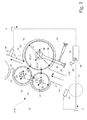
- the conditioning device 13 is designed as a so-called three-roll cracker 16.
- the conditioning rollers 17, 18, 19 of the conditioning device 13 are rotatably mounted in a roller housing 20, which can be integrated via not shown connecting means 21 in the discharge chute 15 in a region between the chopper unit 10 and the post-accelerator 14.
- the conditioning rollers 17-19 comprise a conditioning roller 19 of large diameter D and two further conditioning rollers 17, 18 of small diameter d, wherein the conditioning rollers 17-19 are arranged in the roller housing 20, that the conditioning roller 19 of large diameter D the the conditioning device 13 passing Erntegutstrom 7 bounded at the bottom, while the two conditioner rollers 17, 18 of small diameter d limit the Erntegutstrom 7 above.
- the Konditionietwalzen 17-19 can change their position to each other. In the simplest case, this can be effected by each of the conditioning rollers 17-19 according to the in Fig. 2 schematically drawn arrow directions 28 can be moved or pivoted so that the respective gap widths 26, 27 increase or decrease. Depending on whether a displacement and / or pivoting of the conditioning rollers 17-19 should be provided, the conditioning rollers 17-19 can be guided pivotably in non-illustrated push joints 29 and / or by means of pivot levers 30. Notwithstanding the in Fig.2 By way of example, each of the conditioning rollers 17-19 could be guided either via pivot levers 30 or push joints 29 to effect a change in the gap width 26, 27 of the passage slots 23, 25.
- the respective thrust or pivoting movement can be designed so that the conditioning rollers 17-19 can be changed either in stages or steplessly in their position to each other.
- this can be realized, for example, by the fact that the conditioning rollers 17-19 can either be fixed in fixed detent positions or can be steplessly moved into a desired position by means of actuating cylinders 31 and can be locked therein.
- the conditioning rollers 17, 18 of small diameter d are connected via a coupling member 32 and this coupling member 32 is displaced or guided pivotally, it can be ensured that when changing the position of these conditioning rollers 17, 18, the gap width 26, 27 of the passage column 23, 25 changes in a fixed relationship to each other. Due to the fact that the farmer often wants to change the degree of comminution as a function of the crop and its properties, it is further provided that the gap width 26, 27 of the through-gaps 23, 25 depend on Erntegutparametern, such as the Erntegutart and / or the Erntegutfeuchte, and a desired degree of comminution, such as an achievable cut length or particle size is changeable.
- this can be effected by providing well-known material flow detection devices 33, which are not shown in detail, which can sense the properties of the crop 7, such as the particle size and the good moisture.
- the generated Gutfeuchtes signals Z and Zerklein mecanicsgradsignale Y are finally transmitted to an evaluation unit 34, in the simplest case characteristics 35 are deposited, the optimum gap widths 26, 27 of the passage gaps 23, 25 depending on the moisture content or to be achieved degree of comminution of Erntegutstromes 7 define.
- the device can also be designed such that the operator of the forage harvester 2 specifies an amount of comminution via an input device 36 and evaluation unit 34 uses a so-called desired actual value comparison to determine the predetermined degree of comminution with the crop flow detecting device 33 arranged downstream of the conditioning device 13
- the calculated degree of comminution compares and, depending on the result of the comparison, automatically triggers an adaptation of the gap widths 26, 27 of the passage gaps 23, 25, without the operator of the forage harvester 2 being actively involved in this adaptation process
- the conditioning device 13 is also integrated into the chute 15, that the lying in its inlet region 22 passage gap 23 is located directly in the direction of movement 37 of entering the conditioning 13 Erntegutstromes 7, while the exit gap 24 in the passage gap 25th is positioned so that the transported through it crop stream 7 is discharged directly in the direction of the entrance slit 38 of the Nachbeschreibungsorgans 14.
- the change in the gap width 26 of the required passage gap 23 is made by the operator of the forage harvester 2 for the purpose of setting the coarse crumbling and the change of the gap width 27 of the downstream passage gap 25 for the purpose of setting the fine comminution as a function of the sensed degree of comminution by the operator or automatically.
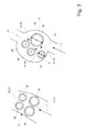
- paired conditioning rollers 39 comprises, so that in each case between the paired conditioning rollers 39 in an analogous manner, the described passage gaps 23, 25 different gap width 26, 27 result. It is also according to Fig.
- a large number of conditioning rollers 40 of small diameter d are assigned to a single conditioning roller 19 of large diameter D, whereby a multiplicity of passage gaps 41 can result which have a gap width 42 decreasing from the inlet region 22 to the outlet region 24 in the manner according to the invention
Landscapes
- Life Sciences & Earth Sciences (AREA)
- Environmental Sciences (AREA)
- Crushing And Grinding (AREA)
- Soil Working Implements (AREA)
- Apparatuses For Bulk Treatment Of Fruits And Vegetables And Apparatuses For Preparing Feeds (AREA)
- Sorting Of Articles (AREA)
- Crushing And Pulverization Processes (AREA)
Abstract
Description
- Die Erfindung betrifft einen Feldhäcksler nach dem Oberbegriff des Anspruchs 1, dessen Einzugsorgane das Erntegut einem Häckselaggregat zuführen und wobei dem Häckselaggregat eine zumindest zwei Gutdurchgangsspalte aufweisende Konditioniereinrichtung nachgeordnet ist.
- Aus der
DE 195 49 504 ist ein gattungsgemäßer Feldhäcksler bekannt geworden, dessen Häckselaggregat eine drei Nachzerkleinerungswalzen umfassende Konditioniereinrichtung nachgeordnet ist. Die Nachzerkleinerungswalzen sind so zueinander angeordnet, dass sich zwischen ihren Umfangsflächen zumindest zwei Gutdurchgangsspalte ausbilden, durch welche das von dem Häckselaggregat zerkleinerte Erntegut geführt wird. Damit die Nachzerkleinerungseinrichtung eine intensive Nachzerkleinerung des Erntegutes bewirkt, weisen alle Nachzerkleinerungswalzen unterschiedliche Umfangsgeschwindigkeiten auf, sodass die sich dabei ergebende Relativbewegung zwischen den in dem jeweiligen Durchgangsspalt benachbarten Nachzerkleinerungswalzen zu einem Reibeffekt auf dem Erntegut führt. Die Umfangsgeschwindigkeiten der Nachzerkleinerungswalzen sind so aufeinander abgestimmt, dass die untere Nachzerkleinerungswelze mit der niedrigsten Umfangsgeschwindigkeit betrieben wird während die ausgangsseitig angeordnete Nachzerkleinerungswalze mit der höchsten Umfangsgeschwindigkeit umläuft und die am Eingang der Konditioniereinrichtung angeordnete Konditionierwalze eine Umfangsgeschwindigkeit aufweist, die zwischen den Umfangsgeschwindigkeiten der übrigen Konditionierwalzen liegt. Eine solche Struktur hat einerseits wegen der sukzessiven Erhöhung der Umfangsgeschwindigkeit der oberen Konditionierwalzen den Vorteil, dass der Zerkleinerungseffekt allmählich gesteigert wird. Aufgrund dessen, dass die Spaltweite der Durchgangsspalte stets konstant ist, besteht bei einer derartigen Ausführung insbesondere das Problem, dass bei hohen Erntegutdurchsätzen ein Gutstau am ersten Durchgangsspalt auftreten kann, da die durch den konstanten Durchgangsspalt förderbare Erntegutmenge begrenzt ist. Zudem steigen bei hohen Erntegutdurchsätzen neben dem erforderlichen Energiebedarf zur Zerkleinerung die Belastungen der Zerkleinerungsorgane sprunghaft an. - Damit der jeweilige Durchgangsspalt in Abhängigkeit vom Erntegutdurchsatz änderbar ist, ist aus der
DE 195 32 290 eine Ausführung bekannt geworden, deren Konditionierwalzen gegen die Wirkung eines Kraftspeichers, wie etwa einem Druckfederpaket, verschwenkbar gelagert sind. In Abhängigkeit von dem zu bewältigenden Erntegutdurchsatz werden die Konditionierwalzen gegen die Wirkung des Kraftspeichers durch den zu fördernden Erntegutstrom selbst verschwenkt, sodass sich schließlich ein größerer Durchgangsspalt ergibt. Aufgrund dessen, dass bei einer derartigen Ausführung die Änderung des Durchgangsspaltes ausschließlich von dem Verhältnis der vom Erntegutdurchsatz auf die Konditionierwalzen wirkenden Kräfte und der Gegenkraft des Kraftspeichers abhängt, ist es nur eingeschränkt möglich, das Erntegut einem gezielten Zerkleinerungseffekt auszusetzen. - Es ist deshalb Aufgabe der Erfindung die beschriebenen Nachteile des Standes der Technik zu vermeiden und insbesondere eine Konditioniereinrichtung vorzuschlagen, die eine gezielte Beeinflussung des Zerkleinerungseffektes bei moderatem Energiebedarf und moderaten auf die Konditioniereinrichtung wirkenden Belastungen zulässt.
- Diese Aufgabe wird erfindungsgemäß durch die kennzeichnenden Merkmale der Anspruchs 1 gelöst.
- Indem die Spaltweite der zumindest zwei Durchgangsspalte in der Weise einstellbar ist, dass die Spaltweite des im Eintrittsbereich der Konditioniereinrichtung angeordneten Durchgangsspaltes größer als die Spaltweite eines in Gutflussrichtung nachgeordneten Durchgangsspaltes ist, wird sichergestellt, dass eine gezielte Beeinflussung des Zerkieinerungseffektes bei moderatem Energiebedarf und moderaten auf die Konditioniereinrichtung wirkenden Belastungen möglich wird.
- In einer vorteilhaften Ausgestaltung der Erfindung kann die jeweilige Spaltweite in Stufen oder stufenlos eingestellt werden, sodass eine hochflexible Anpassung der Zerkleinerung des Erntegutstromes vorgenommen werden kann.
- Indem in einer vorteilhaften Weiterbildung der Erfindung, die Spaltweiten des vorgeordneten und des nachgeordneten Durchgangsspaltes in einem festen Verhältnis zueinander einstellbar sind, wird es möglich, die Konditionierwalzen gemeinschaftlich mittels eines einzigen Verschwenk- und/oder Verschiebemechanismus in verschiedene Positionen zu bewegen.
- Eine besonders effiziente und optimal an die spezifischen Gegebenheiten des jeweils bearbeiteten Erntegutes angepasste Gutzerkleinerung wird dann erreicht, wenn die Spaltweiten der Durchgangsspalte in Abhängigkeit von Ernetgutparametern und/oder dem Zerkleinerungsgrad des Erntegutes einstellbar sind. In diesem Zusammenhang ist es von besonderem Vorteil, wenn der Erntegutparameter die Erntegutart und/oder die Erntegutfeuchte und der Zerkleinerungsgrad die gewünschte Schnittlänge und/oder die Partikelgröße der Teilchen des Erntegutstromes umfassen.
- Eine energieeffiziente Gutförderung und -umlenkung wird in einer vorteilhaften Weiterbildung der Erfindung dann erreicht, wenn die Konditioniereinrichtung in dem Auswurfkrümmer in Gutflussrichtung zwischen dem Häckselaggregat und einem Nachbeschleunigungsorgan positioniert ist und die Konditionierwalzen in einer Weise zueinander angeordnet sind, dass der fordere Durchgangsspalt in der Gutflussrichtung des in die Konditioniereinrichtung eintretenden Gutstromes liegt und der nachgeordnete Durchgangsspalt so angeordnet ist, dass der aus der Konditioniereinrichtung austretende Gutstrom in Richtung des Einstrittsspaltes des Nachbeschleunigungsorgans abgegeben wird.
- Eine konstruktive einfach gestaltete und dennoch effizient zerkleinernde Konditioniereinrichtung ergibt sich dann, wenn die Konditioniereinrichtung als Dreiwalzenkonditionierer ausgeführt ist und eine Konditionierwalze unterhalb und die zwei weiteren Konditionierwalzen oberhalb des durch die Durchgangsspalte geförderten Erntegutstromes angeordnet sind.
- Indem in einer vorteilhaften Ausgestaltung eines Dreiwalzenkonditionierers die unterhalb des Erntegutstromes angeordnete Konditionierwalze den größeren Walzendurchmesser aufweist und die oberhalb des Erntegutstromes angeordneten Konditionierwalzen einen gleichen aber kleineren Walzendurchmesser aufweisen wird sichergestellt, dass sich ein akzeptabler Kompromiss zwischen Intensität der Gutumlenkung in der Konditioniereinrichtung und der Anzahl der erforderlichen Durchgangsspalte ergibt.
- Eine weitere Optimierung des Gutumlenkprozesses in der Konditioniereinrichtung kann dann erreicht werden, wenn in einer vorteilhaften Ausgestaltung der Erfindung die Konditioniereinrichtung paarweise angeordnete Konditionierwalzen umfasst und wobei sich jeweils zwischen den paarweise angeordneten Konditionierwalzen ein Durchgangsspalt ergibt.
- Eine weitere Optimierung des Zerkleinerungsprozesses unter energetischen und Belastungsgesichtspunkten ergibt sich auch dann, wenn in einer vorteilhaften Weiterbildung der Erfindung die Konditioniereinrichtung als Vielwalzenkonditionierer ausgeführt ist und zumindest eine Konditionierwalze unterhalb und die Vielzahl weiterer Konditionierwalzen oberhalb des durch die Durchgangsspalte geförderten Erntegutstromes angeordnet sind. Dies ist insbesondere darauf zurückzuführen, dass bei einer solchen Ausgestaltung der Konditioniereinrichtung eine Vielzahl von Durchgangsspalten realisiert werden können, sodass der an dem jeweiligen Durchgangsspalt erforderliche Zerkleinerungseffet geringer und damit energetisch günstiger umsetzbar ist. In diesem Zusammenhang ist es auch von Vorteil, wenn die zumindest eine unterhalb des Erntegutstromes angeordnete Konditionierwalze und die Vielzahl oberhalb des Erntegutstromes angeordneten Konditionierwalzen zwischen sich Durchgangsspalte ausbilden und wobei die Durchgangsspalte eine vom Eintrittsbereich zum Austrittsbereich der Konditioniereinrichtung abnehmende Spaltweite aufweisen.
- Eine hohe Flexibilität in der Einstellung der Spaltweiten der verschiedenen Durchgangsspalte ergibt sich in vorleilhafter Weiterbildung der Erfindung insbesondere dann, wenn entweder die oberhalb des Gutstromes angeordneten Konditionierwalzen oder die unterhalb des Gutstromes angeordneten Konditionierwalzen oder alle Konditionierwalzen in ihrer Position änderbar gelagert sind.
- Der Zerkleinerungseffekt der Konditioniereinrichtung kann auch dadurch optimal auf die Bedingungen des zu bearbeitenden Erntegutes abgestimmt werden, dass die Änderung der Spaltweite des im Eintrittsbereich der Konditioniereinrichtung liegenden Durchgangsspaltes zwecks Einstellung der Grobzerkleinerung vom dem Betreiber des Feldhäckslers vorgenommen wird und die Änderung der Spaltweite des oder der nachgeordneten Durchgangsspalte zwecks Einstellung der Feinzerkleinerung in Abhängigkeit von dem sensierten Zerkleinerungsgrad vom Betreiber oder automatisch vorgenommen wird. Eine derartige Anpassung des Zerkleinerungseffektes wird insbesondere dann auf einfache Weise möglich, wenn der Zerkleinerungsgrad mittels einer Detektionseinrichtung im Auswurfkrümmer ermittelt wird.
- Weitere vorteilhafte Ausgestaltungen sind Gegenstand weiterer Unteransprüche und werden nachfolgend an Hand in mehreren Figuren dargestellter Ausführungsbeispiele beschrieben, Es zeigen:
- Figur 1
- eine schematische Seitenansicht eines Feldhäckslers mit erfindungsgemäßer Konditioniereinrichtung
- Figur 2
- eine Detailansicht der erfindungsgemäßen Konditioniereinrichtung
- Figur 3
- weitere Ausführungsformen der erfindungsgemäßen Konditioniereinrichtung
- In
Fig. 1 ist eine als selbstfahrender Feldhäcksler 2 ausgeführte landwirtschaftliche Arbeitsmaschine 1 abgebildet, der im frontseitigen Bereich zur Aufnahme von Erntegut 3 ein an sich bekanntes und deshalb nicht näher dargestelltes Vorsatzgerät 4 zugeordnet ist. In an sich bekannter Weise wird das aufgenommene Erntegut 3 mittels zumindest eines Querförderorgans 6 zu einem Erntegutstrom 7 zusammengeführt und an paarweise angeordnete als Einzugs- und Vorpresswalzen 8 ausgeführte Einzugsorgane 9 übergeben, die den Erntegutstrom 7 zunächst vorverdichten und schließlich in ihrem rückwärtigen Bereich an das Häckselaggregat 10 übergeben. Die umlaufenden Messer 11 des Häckselaggregats 10 zerkleinern im Zusammenwirken mit einer ortsfesten Gegenschneide 12 den Erntegutstrom 7 und übergeben ihn schließlich im rückwärtigen Bereich des Häckselaggregats 10 an eine noch näher zu beschreibende erfindungsgemäße Konditioniereinrichtung 13, wie etwa einen sogenannten Korncracker. Die Konditioniereinrichtung 13 übergibt schließlich in ihrem rückwärtigen Bereich den aus ihr austretenden Erntegutstrom 7 an einen Nachbeschleuniger 14 der die kinetische Energie des Erntegutstromes 7 so erhöht, dass der Erntegutstrom 7 einen obenseitig offenen Auswurfkrümmer 15 durchlaufen und aus diesem zur Übergabe an ein nicht dargestelltes Transportfahrzeug austreten kann. - In
Figur 2 ist nun die erfindungsgemäße Konditioniereinrichtung 13 im Detail beschrieben. Im dargestellten Ausführungsbeispiel ist die Konditioniereinrichtung 13 als sogenannter Dreiwalzencracker 16 ausgeführt. Die Konditionierwalzen 17, 18, 19 der Konditioniereinrichtung 13 sind in einem Walzengehäuse 20 drehbar gelagert, welches über nicht näher dargestellte Verbindungsmittel 21 in den Auswurfkrümmer 15 in einem Bereich zwischen dem Häckselaggregat 10 und dem Nachbeschleuniger 14 integriert werden kann. Die Konditionierwalzen 17-19 umfassen eine Konditionierwalze 19 großen Durchmessers D und zwei weitere Konditionierwalzen 17, 18 kleinen Durchmessers d, wobei die Konditionierwalzen 17-19 so in dem Walzengehäuse 20 angeordnet sind, dass die Konditionierwalze 19 großen Durchmessers D den die Konditioniereinrichtung 13 durchlaufenden Erntegutstrom 7 untenseitig begrenzt, während die beiden Konditionserwalzen 17, 18 kleinen Durchmessers d den Erntegutstrom 7 obenseitig begrenzen. Diese Art der Anordnung der Konditionierwalzen 17-19 zueinander führt zugleich dazu, dass sich zwischen den Konditionierwalzen 17-19 in erfindungsgemäßer Weise im Eintrittsbereich 22 der Konditioniereinrichtung 13 ein erster Durchgangsspalt 23 und im Austrittsbereich 24 der Konditioniereinrichtung 13 zumindest ein weiterer Durchgangsspalt 25 ausbildet Zugleich sind die Konditionierwalzen 13 so zueinander angeordnet, dass die Spaltweite 26 des im Eintrittsbereich 22 liegenden Durchgangsspaltes 23 stets größer ist als die Spaltweite 27 des im Austrittsbereich 24 liegenden Durchgangsspaltes 25. Auf dieses Weise wird zunächst sichergestellt dass die Zerkleinerung des Erntegutstromes 7 nur allmählich zunimmt, sodass neben der erforderlichen Zerkleinerungsenergie auch die von der Konditioniereinrichtung 13 zu bewältigenden Belastungen moderat ausfallen. - In einer vorteilhaften Ausgestaltung der Erfindung ist vorgesehen, dass die Konditionietwalzen 17-19 ihre Position zueinander ändern können. Im einfachsten Fall kann dies dadurch bewirkt werden, dass jede der Konditionierwalzen 17-19 gemäß den in
Fig. 2 schematisch eingezeichneten Pfeilrichtungen 28 verschoben oder verschwenkt werden kann, sodass sich die jeweiligen Spaltweiten 26, 27 vergrößern oder verkleinern. Je nach dem, ob ein Verschieben und/oder Verschwenken der Konditionierwalzen 17-19 vorgesehen sein soll, können die Konditionierwalzen 17-19 in nicht näher dargestellten Schubgelenken 29 und/oder mittels Schwenkhebeln 30 schwenkbeweglich geführt sein. Abweichend von der inFig.2 beispielhaft gewählten Darstellung könnte jede der Konditionierwalzen 17-19 entweder über Schwenkhebel 30 oder Schubgelenke 29 geführt werden, um eine Änderung der Spaltweite 26, 27 der Durchgangsspalte 23, 25 zu bewirken. Die jeweilige Schub- oder Schwenkbewegung kann dabei so ausgestaltet sein, dass die Konditionierwalzen 17-19 entweder in Stufen oder stufenlos in ihrer Position zueinander verändert werden können. In einer einfachen konstruktiven Umsetzung kann dies beispielsweise dadurch realisiert werden, dass die Konditionierwalzen 17-19 entweder in festgelegten Rastpositionen fixiert werden können oder mittels Stellzylindern 31 stufenlos in eine gewünschte Position beweg- und in dieser arretierbar sind. - Indem beispielsweise die Konditionierwalzen 17, 18 kleinen Durchmessers d über ein Koppelglied 32 miteinander verbunden sind und dieses Koppelglied 32 verschieb- oder verschwenkbar geführt wird, kann sichergestellt werden, dass sich bei Positionsänderung dieser Konditionierwalzen 17, 18 die Spaltweite 26, 27 der Durchgangsspalte 23, 25 in einem festen Verhältnis zueinander ändert. Aufgrund dessen, dass der Landwirt den Zerkleinerungsgrad häufig in Abhängigkeit von der Gutart und deren Eigenschaften ändern möchte, ist weiter vorgesehen, dass die Spaltweite 26, 27 der Durchgangsspalte 23, 25 in Abhängigkeit von Erntegutparametern, wie etwa der Erntegutart und/oder der Erntegutfeuchte, sowie einem gewünschten Zerkleinerungsgrad, etwa einer zu erreichenden Schnittlänge oder Partikelgröße, änderbar ist. In einer einfachen konstruktiven Ausgestaltung kann dies dadurch bewirkt werden, dass nicht näher dargestellte und an sich bekannte Gutstromdetektionseinrichtungen 33 vorgesehen sind, die Eigenschaften des Erntegutsromes 7, wie etwa die Partikelgröße und die Gutfeuchtigkeit sensieren können. Die generierten Gutfeuchtesignale Z und Zerkleinerungsgradsignale Y werden schließlich an eine Auswerteinheit 34 übermittelt, in der im einfachsten Fall Kennlinien 35 hinterlegt sind, die optimale Spaltweiten 26, 27 der Durchgangsspalte 23, 25 in Abhängigkeit vom Feuchtegehalt oder dem zu erzielenden Zerkleinerungsgrad des Erntegutstromes 7 definieren. Bezüglich des Zerkleinerungsgrades kann die Vorrichtung auch so beschaffen sein, dass der Betreiber des Feldhäckslers 2 über eine Eingabeeinrichtung 36 einen Zerkleinerungsgrad vorgibt und Auswerteinheit 34 über einen sogenannten Soll-lst-Wert-Vergleich den vorgegebenen Zerkleinerungsgrad mit dem von der der Konditioniereinrichtung 13 nachgeordneten Gutstromdetektionseinrichtung 33 ermittelten Zerkleinerungsgrad vergleicht und in Abhängigkeit von dem Ergebnis des Vergleichs automatisch eine Anpassung der Spaltweiten 26, 27 der Durchgangsspalte 23, 25 auslöst, ohne dass der Betreiber des Feldhäckslers 2 in diesen Anpassungsprozess aktiv eingebunden ist
- In einer weiteren vorteilhaften Ausgestaltung der Erfindung ist die Konditioniereinrichtung 13 zudem so in den Auswurfkrümmer 15 integriert, dass der in ihrem Eintrittsbereich 22 liegende Durchgangsspalt 23 unmittelbar in Bewegungsrichtung 37 des in die Konditioniereinrichtung 13 eintretenden Erntegutstromes 7 liegt, während der im Austrittsbereich 24 liegende Durchgangsspalt 25 so positioniert ist, dass der durch ihn hindurchgeförderte Erntegutstrom 7 unmittelbar in Richtung des Eintrittsspaltes 38 des Nachbeschleunigungsorgans 14 abgegeben wird.
- In dem beschriebenen Ausführungsbeispiel wird aufgrund der größeren Spaltweite 26 des im Eintrittsbereich 22 der Konditioniereinrichtung 13 liegenden Durchgangsspaltes 23 in diesem eine Grobzerkleinerung des Erntegutstromes 7 vorgenommen, während die geringere Spaltweite 27 des nachgeordneten Durchgangsspaltes 25 zu einer Feinzerkleinerung des Erntegutstromes 7 führt. In einer weiteren Ausgestaltung der Erfindung kann auch vorgesehen sein, dass die Änderung der Spaltweite 26 des forderen Durchgangsspaltes 23 zwecks Einstellung der Grobzerkleitierung vom dem Betreiber des Feldhäckslers 2 vorgenommen wird und die Änderung der Spaltweite 27 des nachgeordneten Durchgangsspaltes 25 zwecks Einstellung der Feinzerkleinerung in Abhängigkeit von dem sensierten Zerkleinerungsgrad vom Betreiber oder automatisch erfolgt.
- Es liegt im Rahmen der Erfindung, dass die beschriebene Konditioniereinrichtung 13 gemäß
Fig. 3 paarweise angeordnete Konditionierwalzen 39 umfasst, sodass sich jeweils zwischen den paarweise angeordneten Konditionierwalzen 39 in analoger Weise die beschriebenen Durchgangsspalte 23, 25 unterschiedlicher Spaltweite 26, 27 ergeben. Auch liegt es gemäßFig. 3 im Rahmen der Erfindung, dass einer einzigen Konditionierwalze 19 großen Durchmessers D eine Vielzahl von Konditionierwalzen 40 kleinen Durchmessers d zugeordnet sind, wobei sich dann eine Vielzahl von Durchgangsspalten 41 ergeben kann, die in erfindungsgemäßer Weise eine vom Eintrittsbereich 22 zum Austrittsbereich 24 abnehmende Spaltweite 42 aufweisen.Bezugszeichenliste: 1 landwirtschaftliche Arbeitsmaschine 31 Stellzylinder 2 Feldhäcksler 32 Koppelglied 3 Erntegut 33 Gutstromdetektionseinrichtung 4 Vorsatzgerät 34 Auswerteinheit 5 35 Kennlinie 6 Querförderorgan 36 Eingabeeinrichtung 7 Erntegutstrom 37 Bewegungsrichtung 8 Einzugs- und Vorpresswalzen 38 Eintrittsspalt 9 Einzugsorgan 39 Konditionierwalze 10 Häckselaggregat 40 Konditionierwalze 11 Messer 41 Durchgangsspalt 12 Gegenschneide 42 Spaltweite 13 Konditioniereinrichtung 14 Nachbeschleuniger 15 Auswurfkrümmer D großer Walzendurchmesser 16 Dreiwalzencracker d kleiner Walzendurchmesser 17 Konditionierwalze Z Gutfeuchtesignal 18 Konditionierwalze Y Zerkleinerungsgradsignal 19 Konditionierwalze 20 Walzengehäuse 21 Verbindungsmittel 22 Eintrittsbereich 23 Durchgangsspalt 24 Austrittsbereich 25 Durchgangsspalt 26 Spaltweite 27 Spaltweite 28 Pfeilrichtung 29 Schubgelenk 30 Schwenkgelenk
Claims (15)
- Feldhäcksler mit das Häckselgut einem nachgeordneten Häckselaggregat zuleitenden Einzugsorganen und einem dem Häckselaggregat nachgeordneten Auswurfkrümmer sowie aus einer rotierend antreibbaren Walzenanordnung bestehenden Konditioniereinrichtung, die zwischen dem Häckselaggregat und dem Auswurfkrümmer angeordnet ist und wobei die Konditionierwalzen der Konditioniereinrichtung zumindest zwei Gutdurchgangsspalte ausbilden,
dadurch gekennzeichnet,
dass die Spaltweite (26,27,42) der zumindest zwei Durchgangsspalte (23, 25, 41) in der Weise einstellbar ist, dass die Spaltweite (26, 42) des im Eintrittsbereich (22) der Konditioniereinrichtung (13) angeordneten Durchgangsspaltes (23, 41) größer als die Spaltweite (27,42) eines in Gutflussrichtung (37) nachgeordneten Durchgangsspaltes (25, 41) ist. - Feldhäcksler nach Anspruch 1,
dadurch gekennzeichnet,
dass die jeweilige Spaltweite (26, 27, 42) in Stufen oder stufenlos einstellbar ist. - Feldhäcksler nach einem der vorhergehenden Ansprüche,
dadurch gekennzeichnet,
dass die Spaltweiten (26, 27, 42) des vorgeordneten und des nachgeordneten Durchgangsspaltes (23, 25, 41) in einem festen Verhältnis zueinander einstellbar sind. - Feldhäcksler nach einem der vorhergehenden Ansprüche,
dadurch gekennzeichnet,
dass die Spaltweiten (26, 27, 42) der Durchgangsspalte (23, 25, 41) in Abhängigkeit von Ernetgutparametern und/oder dem Zerkleinerungsgrad des Erntegutes (7) einstellbar sind. - Feldhäcksler nach Anspruch 4,
dadurch gekennzeichnet,
dass der Erntegutparameter die Erntegutart und/oder die Erntegutfeuchte umfasst. - Feldhäcksler nach Anspruch 4,
dadurch gekennzeichnet,
dass der Zerkleinerungsgrad die gewünschte Schnittlänge und/oder die Partikelgröße der Teilchen des Erntegutstromes (7) umfasst. - Feldhäcksler nach einem der vorhergehenden Ansprüche,
dadurch gekennzeichnet,
dass die Konditioniereinrichtung (13) in dem Auswurfkrümmer (15) in Gutflussrichtung (37) zwischen dem Häckselaggregat (10) und einem Nachbeschleunigungsorgan (14) positioniert ist und die Konditionierwalzen (18, 19, 39, 40) in einer Weise zueinander angeordnet sind, dass der fordere Durchgangsspalt (23, 41) in der Gutflussrichtung (37) des in die Konditioniereinrichtung (13) eintretenden Gutstromes (7) liegt und der nachgeordnete Durchgangsspalt (25, 41) so angeordnet ist, dass der aus der Konditioniereinrichtung (13) austretende Gutstrom (7) in Richtung des Eintrittsspaltes (38) des Nachbeschleunigungsorgans (14) abgegeben wird. - Feldhäcksler nach Anspruch 7,
dadurch gekennzeichnet,
dass die Konditioniereinrichtung (13) als Dreiwalzenkonditionierer ausgeführt ist und eine Konditionierwalze (19) unterhalb und die zwei weiteren Konditionierwalzen (17, 18) oberhalb des durch die Durchgangsspalte (23, 25, 41) geförderten Erntegutstromes (7) angeordnet sind, - Feldhäcksler nach Anspruch 8,
dadurch gekennzeichnet,
dass die unterhalb des Erntegutstromes (7) angeordnete Konditionierwalze (19) den größeren Walzendurchmesser (D) aufweist und die oberhalb des Erntegutstromes (7) angeordneten Konditionierwalzen (17, 18) einen gleichen aber kleineren Walzendurchmesser (d) aufweisen, - Feldhäcksler nach Anspruch 7,
dadurch gekennzeichnet,
dass die Konditioniereinrichtung (13) paarweise angeordnete Konditionierwalzen (39) umfasst und wobei sich jeweils zwischen den paarweise angeordneten Konditionierwalzen (39) ein Durchgangsspalt (23, 25) ergibt. - Feldhäcksler nach Anspruch 7,
dadurch gekennzeichnet,
dass die Konditioniereinrichtung (13) als Vielwalzenkonditionierer ausgeführt ist und zumindest eine Konditionierwalze (19) unterhalb und die Vielzahl weiterer Konditionierwalzen (40) oberhalb des durch die Durchgangsspalte (41) geförderten Erntegutstromes (7) angeordnet sind. - Feldhäcksler nach Anspruch 11,
dadurch gekennzeichnet,
dass die zumindest eine unterhalb des Erntegutstromes (7) angeordnete Konditionierwalze (19) und die Vielzahl oberhalb des Erntegutstromes (7) angeordneten Konditionierwalzen (40) zwischen sich Durchgangsspalte (41) ausbilden und wobei die Durchgangsspalte (41) eine vom Eintrittsbereich (22) zum Austrittsbereich (24) der Konditioniereinrichtung (13) abnehmende Spaltweite (42) aufweisen. - Feldhäcksler nach einem der vorhergehenden Ansprüche,
dadurch gekennzeichnet,
dass entweder die oberhalb des Gutstromes (7) angeordneten Konditionierwalzen (17, 18, 39, 40) oder die unterhalb des Gutstromes (7) angeordneten Konditionierwalzen (19, 39) oder alle Konditionierwalzen (17-19, 39, 40) in ihrer Position änderbar gelagert sind. - Feldhäcksler nach einem der vorhergehenden Ansprüche,
dadurch gekennzeichnet,
dass die Änderung der Spaltweite (26, 42) des im Eintrittsbereich (22) der Konditioniereinrichtung (13) liegenden Durchgangsspaltes (23, 41) zwecks Einstellung der Grobzerkleinerung vom dem Betreiber des Feldhäckslers (2) vorgenommen wird und die Änderung der Spaltweite (27, 42) des oder der nachgeordneten Durchgangsspalte (25, 41) zwecks Einstellung der Feinzerkleinerung in Abhängigkeit von dem sensierten Zerkleinerungsgrad vom Betreiber oder automatisch vorgenommen wird. - Feldhäcksler nach Anspruch 14,
dadurch gekennzeichnet,
dass der Zerkleinerungsgrad mittels einer Detektionseinrichtung (33) im Auswurfkrümmer (15) ermittelt wird.
Applications Claiming Priority (1)
| Application Number | Priority Date | Filing Date | Title |
|---|---|---|---|
| DE102007018885A DE102007018885A1 (de) | 2007-04-19 | 2007-04-19 | Landwirtschaftliche Arbeitsmaschine |
Publications (2)
| Publication Number | Publication Date |
|---|---|
| EP1982573A1 true EP1982573A1 (de) | 2008-10-22 |
| EP1982573B1 EP1982573B1 (de) | 2010-07-07 |
Family
ID=39472813
Family Applications (1)
| Application Number | Title | Priority Date | Filing Date |
|---|---|---|---|
| EP08101037A Not-in-force EP1982573B1 (de) | 2007-04-19 | 2008-01-29 | Landwirtschaftliche Arbeitsmaschine |
Country Status (5)
| Country | Link |
|---|---|
| US (1) | US20080261670A1 (de) |
| EP (1) | EP1982573B1 (de) |
| AT (1) | ATE472935T1 (de) |
| DE (2) | DE102007018885A1 (de) |
| RU (1) | RU2457661C2 (de) |
Cited By (4)
| Publication number | Priority date | Publication date | Assignee | Title |
|---|---|---|---|---|
| EP2452554A1 (de) * | 2010-11-11 | 2012-05-16 | Putsch GmbH & Co. KG | Maschinenanlage zur Aufbereitung von Feldfrüchten |
| WO2013067119A1 (en) * | 2011-11-01 | 2013-05-10 | Agco Corporation | Chopper attachment to improve conditioning of bio-mass type crops |
| EP2796031A1 (de) * | 2013-04-24 | 2014-10-29 | CLAAS Selbstfahrende Erntemaschinen GmbH | Landwirtschaftliche Erntemaschine |
| CN108029354A (zh) * | 2018-01-23 | 2018-05-15 | 杨同基 | 一种畜牧业用草料切割设备 |
Families Citing this family (11)
| Publication number | Priority date | Publication date | Assignee | Title |
|---|---|---|---|---|
| DE102010040106B4 (de) | 2010-09-01 | 2020-01-16 | Deere & Company | Nachbearbeitungseinrichtung für einen Feldhäcksler mit zwei versetzten Bearbeitungsspalten |
| DE102013101183A1 (de) * | 2013-02-07 | 2014-08-07 | Claas Selbstfahrende Erntemaschinen Gmbh | Landwirtschaftliche Arbeitsmaschine, insbesondere Feldhäcksler |
| GB2549945A (en) | 2016-05-03 | 2017-11-08 | Kverneland Group Kerteminde As | Conditioner unit |
| RU188105U1 (ru) * | 2018-02-05 | 2019-03-28 | Общество с ограниченной ответственностью "Комбайновый завод "Ростсельмаш" | Доизмельчитель кормоуборочного комбайна |
| CN108745585A (zh) * | 2018-05-28 | 2018-11-06 | 傅花宁 | 一种废旧砖瓦高效处理装置 |
| US11564349B2 (en) * | 2018-10-31 | 2023-01-31 | Deere & Company | Controlling a machine based on cracked kernel detection |
| US11497161B2 (en) * | 2019-07-15 | 2022-11-15 | Deere & Company | Control system for a mower conditioner implement |
| US11744184B2 (en) | 2020-05-19 | 2023-09-05 | Cnh Industrial America Llc | Roll conditioner adjustment system for an agricultural harvesting machine |
| DE102021113626A1 (de) | 2021-05-26 | 2022-12-01 | Deere & Company | Antriebsanordnung einer Konditioniereinrichtung eines Feldhäckslers mit einem elektrischen Antriebsstrang |
| DE102021113838A1 (de) | 2021-05-28 | 2022-12-01 | Deere & Company | Feldhäcksler mit vorausschauender Ansteuerung des Bearbeitungsgrads eines Körnerprozessors |
| CN120479577B (zh) * | 2025-06-06 | 2026-07-21 | 郑州商学院 | 一种农作物废料返田加工处理设备 |
Citations (4)
| Publication number | Priority date | Publication date | Assignee | Title |
|---|---|---|---|---|
| DE19532290A1 (de) | 1995-09-01 | 1997-03-06 | Claas Ohg | Feldhäcksler |
| DE29719518U1 (de) * | 1997-11-04 | 1997-12-18 | Fortschritt Erntemaschinen Gmbh, 01844 Neustadt | Konditionierwalze für Feldhäcksler |
| DE19549504C2 (de) | 1995-10-13 | 1999-05-27 | Case Harvesting Sys Gmbh | Feldhäcksler mit Konditioniereinrichtung |
| EP1101397A1 (de) * | 1999-11-17 | 2001-05-23 | Case Harvesting Systems GmbH | Konditioniereinrichtung für Feldhäcksler |
Family Cites Families (22)
| Publication number | Priority date | Publication date | Assignee | Title |
|---|---|---|---|---|
| US3851450A (en) * | 1973-06-01 | 1974-12-03 | Deere & Co | Forage harvester |
| DE2459007C3 (de) * | 1974-12-13 | 1979-12-13 | Josef Bautz Gmbh, 7968 Saulgau | Heuwerbungsmaschine |
| SU1033045A1 (ru) * | 1980-09-18 | 1983-08-07 | Предприятие П/Я М-5830 | Измельчающий аппарат уборочных сельскохоз йственных машин |
| US4445313A (en) * | 1982-08-19 | 1984-05-01 | Thomas Elliott | Hay cutting machines |
| US4637201A (en) * | 1984-07-24 | 1987-01-20 | Hesston Corporation | Wide-cut windrower-conditioner having uniform crop distribution and conditioning |
| SU1230538A1 (ru) * | 1984-11-10 | 1986-05-15 | Всесоюзный Научно-Исследовательский Институт По Испытанию Машин И Оборудования Для Животноводства И Кормопроизводства | Измельчитель |
| DE4139221A1 (de) * | 1991-11-22 | 1993-05-27 | Fortschritt Erntemaschinen | Vorrichtung zur aufbereitung von gemaehtem erntegut |
| DE4228857A1 (de) * | 1992-08-29 | 1994-03-03 | Kloeckner Humboldt Deutz Ag | Vorrichtung zur Halmgutaufbereitung |
| US6055799A (en) * | 1995-10-04 | 2000-05-02 | Universite Laval & Agriculture Et Agro-Alimentaire Canada | Forage conditioning machine |
| US6047532A (en) * | 1997-07-21 | 2000-04-11 | Hay & Forage Industries | Long span auger support apparatus for harvesting header |
| DK0931446T3 (da) * | 1998-01-16 | 2003-06-10 | Claas Selbstfahr Erntemasch | Måleindretning på en mobil høstmaskine |
| US6050070A (en) * | 1998-01-29 | 2000-04-18 | Cook; Ivan J. | Crop conditioning system |
| US6431981B1 (en) * | 1999-06-30 | 2002-08-13 | Wisconsin Alumni Research Foundation | Yield monitor for forage crops |
| US6584755B2 (en) * | 2001-08-14 | 2003-07-01 | Deere & Company | Apparatus for adjusting the spacing and/or the contact pressure between two rollers of a kernel processor |
| DE10220699A1 (de) * | 2002-05-10 | 2003-12-24 | Deere & Co | Vorrichtung zur Einstellung der Schnittlänge einer Häckseleinrichtung |
| US6996961B2 (en) * | 2003-11-19 | 2006-02-14 | Acco Corporation | Method and apparatus for conditioning crop materials |
| GB2414373A (en) * | 2004-05-27 | 2005-11-30 | Cnh Belgium Nv | Accelerator and crop processor movement |
| CA2494395C (en) * | 2004-12-15 | 2009-04-07 | Macdon Industries Ltd. | Conditioning roller drive |
| ATE383743T1 (de) * | 2004-12-18 | 2008-02-15 | Deere & Co | Erntemaschine |
| DE102006009575A1 (de) * | 2006-02-28 | 2007-09-06 | Claas Selbstfahrende Erntemaschinen Gmbh | Verfahren und Vorrichtung zur Bestimmung der Verdichtung von Erntegut |
| DE102006019243A1 (de) * | 2006-04-21 | 2007-11-08 | Claas Selbstfahrende Erntemaschinen Gmbh | Verfahren und Vorrichtung zur Einstellung der Schnittlänge einer Häckseleinrichtung einer landwirtschaftlichen Erntemaschine |
| DE102007009587A1 (de) * | 2007-02-26 | 2008-08-28 | Claas Selbstfahrende Erntemaschinen Gmbh | Vorrichtung zur Einstellung der Position des Nachbeschleunigungsorgans in einer landwirtschaftlichen Erntemaschine |
-
2007
- 2007-04-19 DE DE102007018885A patent/DE102007018885A1/de not_active Withdrawn
-
2008
- 2008-01-29 DE DE502008000888T patent/DE502008000888D1/de active Active
- 2008-01-29 AT AT08101037T patent/ATE472935T1/de active
- 2008-01-29 EP EP08101037A patent/EP1982573B1/de not_active Not-in-force
- 2008-04-17 RU RU2008114619/13A patent/RU2457661C2/ru active
- 2008-04-17 US US12/104,859 patent/US20080261670A1/en not_active Abandoned
Patent Citations (4)
| Publication number | Priority date | Publication date | Assignee | Title |
|---|---|---|---|---|
| DE19532290A1 (de) | 1995-09-01 | 1997-03-06 | Claas Ohg | Feldhäcksler |
| DE19549504C2 (de) | 1995-10-13 | 1999-05-27 | Case Harvesting Sys Gmbh | Feldhäcksler mit Konditioniereinrichtung |
| DE29719518U1 (de) * | 1997-11-04 | 1997-12-18 | Fortschritt Erntemaschinen Gmbh, 01844 Neustadt | Konditionierwalze für Feldhäcksler |
| EP1101397A1 (de) * | 1999-11-17 | 2001-05-23 | Case Harvesting Systems GmbH | Konditioniereinrichtung für Feldhäcksler |
Cited By (5)
| Publication number | Priority date | Publication date | Assignee | Title |
|---|---|---|---|---|
| EP2452554A1 (de) * | 2010-11-11 | 2012-05-16 | Putsch GmbH & Co. KG | Maschinenanlage zur Aufbereitung von Feldfrüchten |
| WO2013067119A1 (en) * | 2011-11-01 | 2013-05-10 | Agco Corporation | Chopper attachment to improve conditioning of bio-mass type crops |
| US8984851B2 (en) | 2011-11-01 | 2015-03-24 | Agco Corporation | Chopper attachment to improve conditioning of bio-mass type crops |
| EP2796031A1 (de) * | 2013-04-24 | 2014-10-29 | CLAAS Selbstfahrende Erntemaschinen GmbH | Landwirtschaftliche Erntemaschine |
| CN108029354A (zh) * | 2018-01-23 | 2018-05-15 | 杨同基 | 一种畜牧业用草料切割设备 |
Also Published As
| Publication number | Publication date |
|---|---|
| RU2457661C2 (ru) | 2012-08-10 |
| RU2008114619A (ru) | 2009-10-27 |
| DE102007018885A1 (de) | 2008-10-23 |
| EP1982573B1 (de) | 2010-07-07 |
| DE502008000888D1 (de) | 2010-08-19 |
| ATE472935T1 (de) | 2010-07-15 |
| US20080261670A1 (en) | 2008-10-23 |
Similar Documents
| Publication | Publication Date | Title |
|---|---|---|
| EP1982573B1 (de) | Landwirtschaftliche Arbeitsmaschine | |
| EP1219164B1 (de) | Vorrichtung und Verfahren zur Erntegutförderung in landwirtschaftlichen Arbeitsmaschinen | |
| EP1884155B1 (de) | Landwirtschaftliche Erntemaschine | |
| EP1166619B1 (de) | Vorrichtung zum Einstellen des Abstandes und/oder der Anpresskraft zweier Walzen einer Nachzerkleinerungseinrichtung | |
| EP2689654B1 (de) | Fördervorrichtung und Ballenpresse mit einer solchen | |
| EP2225929B1 (de) | Gutverteileinrichtung für Mähdrescher | |
| DE3302980C2 (de) | ||
| EP3520596B1 (de) | Mähdrescher | |
| EP2289305B1 (de) | Vorrichtung zur Reinigung einer Ballenpresse | |
| DE102007009587A1 (de) | Vorrichtung zur Einstellung der Position des Nachbeschleunigungsorgans in einer landwirtschaftlichen Erntemaschine | |
| BE1026187B1 (de) | Auswurfanordnung zur Anbringung am Ende einer Austrageinrichtung | |
| EP1932419B1 (de) | Landwirtschaftliche Presse | |
| EP1790210B1 (de) | Zuführeinrichtung für einen Feldhäcksler | |
| EP3662737A1 (de) | Selbstfahrender mähdrescher | |
| DE102011013242B4 (de) | Ballenpresse | |
| EP1797753B1 (de) | Feldhäcksler | |
| EP4074162B1 (de) | Rundballenpresse mit starterwalze und elastisch auslenkbarem auslenkelement | |
| DE19532290C2 (de) | Feldhäcksler | |
| EP2025218B1 (de) | Konditioniereinrichtung für einen Feldhäcksler | |
| EP2106686B1 (de) | Konditioniereinrichtung für einen Feldhäcksler | |
| EP3069596B1 (de) | Feldhäcksler | |
| DE102011117385B4 (de) | Erntemaschine | |
| DE3339925C2 (de) | Großballenpresse für landwirtschaftliches Erntegut | |
| EP1820390B1 (de) | Mähdrescher mit mehrstufigem Trennbereich | |
| BE1021289B1 (de) | Nachbearbeitungseinrichtung für einen feldhäcksler mit zwei versetzten bearbeitungsspalten |
Legal Events
| Date | Code | Title | Description |
|---|---|---|---|
| PUAI | Public reference made under article 153(3) epc to a published international application that has entered the european phase |
Free format text: ORIGINAL CODE: 0009012 |
|
| AK | Designated contracting states |
Kind code of ref document: A1 Designated state(s): AT BE BG CH CY CZ DE DK EE ES FI FR GB GR HR HU IE IS IT LI LT LU LV MC MT NL NO PL PT RO SE SI SK TR |
|
| AX | Request for extension of the european patent |
Extension state: AL BA MK RS |
|
| 17P | Request for examination filed |
Effective date: 20090422 |
|
| AKX | Designation fees paid |
Designated state(s): AT BE BG CH CY CZ DE DK EE ES FI FR GB GR HR HU IE IS IT LI LT LU LV MC MT NL NO PL PT RO SE SI SK TR |
|
| GRAP | Despatch of communication of intention to grant a patent |
Free format text: ORIGINAL CODE: EPIDOSNIGR1 |
|
| RIC1 | Information provided on ipc code assigned before grant |
Ipc: A01F 29/09 20100101AFI20100218BHEP |
|
| GRAS | Grant fee paid |
Free format text: ORIGINAL CODE: EPIDOSNIGR3 |
|
| GRAA | (expected) grant |
Free format text: ORIGINAL CODE: 0009210 |
|
| AK | Designated contracting states |
Kind code of ref document: B1 Designated state(s): AT BE BG CH CY CZ DE DK EE ES FI FR GB GR HR HU IE IS IT LI LT LU LV MC MT NL NO PL PT RO SE SI SK TR |
|
| REG | Reference to a national code |
Ref country code: GB Ref legal event code: FG4D Free format text: NOT ENGLISH |
|
| REG | Reference to a national code |
Ref country code: CH Ref legal event code: EP |
|
| REG | Reference to a national code |
Ref country code: IE Ref legal event code: FG4D |
|
| REF | Corresponds to: |
Ref document number: 502008000888 Country of ref document: DE Date of ref document: 20100819 Kind code of ref document: P |
|
| REG | Reference to a national code |
Ref country code: NL Ref legal event code: VDEP Effective date: 20100707 |
|
| PG25 | Lapsed in a contracting state [announced via postgrant information from national office to epo] |
Ref country code: SI Free format text: LAPSE BECAUSE OF FAILURE TO SUBMIT A TRANSLATION OF THE DESCRIPTION OR TO PAY THE FEE WITHIN THE PRESCRIBED TIME-LIMIT Effective date: 20100707 |
|
| LTIE | Lt: invalidation of european patent or patent extension |
Effective date: 20100707 |
|
| PG25 | Lapsed in a contracting state [announced via postgrant information from national office to epo] |
Ref country code: NL Free format text: LAPSE BECAUSE OF FAILURE TO SUBMIT A TRANSLATION OF THE DESCRIPTION OR TO PAY THE FEE WITHIN THE PRESCRIBED TIME-LIMIT Effective date: 20100707 Ref country code: FI Free format text: LAPSE BECAUSE OF FAILURE TO SUBMIT A TRANSLATION OF THE DESCRIPTION OR TO PAY THE FEE WITHIN THE PRESCRIBED TIME-LIMIT Effective date: 20100707 Ref country code: LT Free format text: LAPSE BECAUSE OF FAILURE TO SUBMIT A TRANSLATION OF THE DESCRIPTION OR TO PAY THE FEE WITHIN THE PRESCRIBED TIME-LIMIT Effective date: 20100707 Ref country code: NO Free format text: LAPSE BECAUSE OF FAILURE TO SUBMIT A TRANSLATION OF THE DESCRIPTION OR TO PAY THE FEE WITHIN THE PRESCRIBED TIME-LIMIT Effective date: 20101007 |
|
| REG | Reference to a national code |
Ref country code: IE Ref legal event code: FD4D |
|
| PG25 | Lapsed in a contracting state [announced via postgrant information from national office to epo] |
Ref country code: IS Free format text: LAPSE BECAUSE OF FAILURE TO SUBMIT A TRANSLATION OF THE DESCRIPTION OR TO PAY THE FEE WITHIN THE PRESCRIBED TIME-LIMIT Effective date: 20101107 Ref country code: BG Free format text: LAPSE BECAUSE OF FAILURE TO SUBMIT A TRANSLATION OF THE DESCRIPTION OR TO PAY THE FEE WITHIN THE PRESCRIBED TIME-LIMIT Effective date: 20101007 Ref country code: CY Free format text: LAPSE BECAUSE OF FAILURE TO SUBMIT A TRANSLATION OF THE DESCRIPTION OR TO PAY THE FEE WITHIN THE PRESCRIBED TIME-LIMIT Effective date: 20100707 Ref country code: HR Free format text: LAPSE BECAUSE OF FAILURE TO SUBMIT A TRANSLATION OF THE DESCRIPTION OR TO PAY THE FEE WITHIN THE PRESCRIBED TIME-LIMIT Effective date: 20100707 Ref country code: PL Free format text: LAPSE BECAUSE OF FAILURE TO SUBMIT A TRANSLATION OF THE DESCRIPTION OR TO PAY THE FEE WITHIN THE PRESCRIBED TIME-LIMIT Effective date: 20100707 |
|
| PG25 | Lapsed in a contracting state [announced via postgrant information from national office to epo] |
Ref country code: GR Free format text: LAPSE BECAUSE OF FAILURE TO SUBMIT A TRANSLATION OF THE DESCRIPTION OR TO PAY THE FEE WITHIN THE PRESCRIBED TIME-LIMIT Effective date: 20101008 Ref country code: LV Free format text: LAPSE BECAUSE OF FAILURE TO SUBMIT A TRANSLATION OF THE DESCRIPTION OR TO PAY THE FEE WITHIN THE PRESCRIBED TIME-LIMIT Effective date: 20100707 Ref country code: SE Free format text: LAPSE BECAUSE OF FAILURE TO SUBMIT A TRANSLATION OF THE DESCRIPTION OR TO PAY THE FEE WITHIN THE PRESCRIBED TIME-LIMIT Effective date: 20100707 |
|
| PG25 | Lapsed in a contracting state [announced via postgrant information from national office to epo] |
Ref country code: DK Free format text: LAPSE BECAUSE OF FAILURE TO SUBMIT A TRANSLATION OF THE DESCRIPTION OR TO PAY THE FEE WITHIN THE PRESCRIBED TIME-LIMIT Effective date: 20100707 Ref country code: IE Free format text: LAPSE BECAUSE OF FAILURE TO SUBMIT A TRANSLATION OF THE DESCRIPTION OR TO PAY THE FEE WITHIN THE PRESCRIBED TIME-LIMIT Effective date: 20100707 |
|
| PLBE | No opposition filed within time limit |
Free format text: ORIGINAL CODE: 0009261 |
|
| STAA | Information on the status of an ep patent application or granted ep patent |
Free format text: STATUS: NO OPPOSITION FILED WITHIN TIME LIMIT |
|
| PG25 | Lapsed in a contracting state [announced via postgrant information from national office to epo] |
Ref country code: EE Free format text: LAPSE BECAUSE OF FAILURE TO SUBMIT A TRANSLATION OF THE DESCRIPTION OR TO PAY THE FEE WITHIN THE PRESCRIBED TIME-LIMIT Effective date: 20100707 Ref country code: IT Free format text: LAPSE BECAUSE OF FAILURE TO SUBMIT A TRANSLATION OF THE DESCRIPTION OR TO PAY THE FEE WITHIN THE PRESCRIBED TIME-LIMIT Effective date: 20100707 Ref country code: CZ Free format text: LAPSE BECAUSE OF FAILURE TO SUBMIT A TRANSLATION OF THE DESCRIPTION OR TO PAY THE FEE WITHIN THE PRESCRIBED TIME-LIMIT Effective date: 20100707 Ref country code: SK Free format text: LAPSE BECAUSE OF FAILURE TO SUBMIT A TRANSLATION OF THE DESCRIPTION OR TO PAY THE FEE WITHIN THE PRESCRIBED TIME-LIMIT Effective date: 20100707 Ref country code: RO Free format text: LAPSE BECAUSE OF FAILURE TO SUBMIT A TRANSLATION OF THE DESCRIPTION OR TO PAY THE FEE WITHIN THE PRESCRIBED TIME-LIMIT Effective date: 20100707 |
|
| 26N | No opposition filed |
Effective date: 20110408 |
|
| PG25 | Lapsed in a contracting state [announced via postgrant information from national office to epo] |
Ref country code: ES Free format text: LAPSE BECAUSE OF FAILURE TO SUBMIT A TRANSLATION OF THE DESCRIPTION OR TO PAY THE FEE WITHIN THE PRESCRIBED TIME-LIMIT Effective date: 20101018 |
|
| REG | Reference to a national code |
Ref country code: DE Ref legal event code: R097 Ref document number: 502008000888 Country of ref document: DE Effective date: 20110408 |
|
| PG25 | Lapsed in a contracting state [announced via postgrant information from national office to epo] |
Ref country code: MC Free format text: LAPSE BECAUSE OF NON-PAYMENT OF DUE FEES Effective date: 20110131 |
|
| PG25 | Lapsed in a contracting state [announced via postgrant information from national office to epo] |
Ref country code: MT Free format text: LAPSE BECAUSE OF FAILURE TO SUBMIT A TRANSLATION OF THE DESCRIPTION OR TO PAY THE FEE WITHIN THE PRESCRIBED TIME-LIMIT Effective date: 20100707 |
|
| REG | Reference to a national code |
Ref country code: CH Ref legal event code: PL |
|
| GBPC | Gb: european patent ceased through non-payment of renewal fee |
Effective date: 20120129 |
|
| PG25 | Lapsed in a contracting state [announced via postgrant information from national office to epo] |
Ref country code: CH Free format text: LAPSE BECAUSE OF NON-PAYMENT OF DUE FEES Effective date: 20120131 Ref country code: LI Free format text: LAPSE BECAUSE OF NON-PAYMENT OF DUE FEES Effective date: 20120131 Ref country code: GB Free format text: LAPSE BECAUSE OF NON-PAYMENT OF DUE FEES Effective date: 20120129 |
|
| PG25 | Lapsed in a contracting state [announced via postgrant information from national office to epo] |
Ref country code: LU Free format text: LAPSE BECAUSE OF NON-PAYMENT OF DUE FEES Effective date: 20110129 |
|
| PG25 | Lapsed in a contracting state [announced via postgrant information from national office to epo] |
Ref country code: PT Free format text: LAPSE BECAUSE OF NON-PAYMENT OF DUE FEES Effective date: 20100707 |
|
| PG25 | Lapsed in a contracting state [announced via postgrant information from national office to epo] |
Ref country code: TR Free format text: LAPSE BECAUSE OF FAILURE TO SUBMIT A TRANSLATION OF THE DESCRIPTION OR TO PAY THE FEE WITHIN THE PRESCRIBED TIME-LIMIT Effective date: 20100707 |
|
| PG25 | Lapsed in a contracting state [announced via postgrant information from national office to epo] |
Ref country code: HU Free format text: LAPSE BECAUSE OF FAILURE TO SUBMIT A TRANSLATION OF THE DESCRIPTION OR TO PAY THE FEE WITHIN THE PRESCRIBED TIME-LIMIT Effective date: 20100707 |
|
| REG | Reference to a national code |
Ref country code: AT Ref legal event code: MM01 Ref document number: 472935 Country of ref document: AT Kind code of ref document: T Effective date: 20130129 |
|
| PG25 | Lapsed in a contracting state [announced via postgrant information from national office to epo] |
Ref country code: AT Free format text: LAPSE BECAUSE OF NON-PAYMENT OF DUE FEES Effective date: 20130129 |
|
| REG | Reference to a national code |
Ref country code: FR Ref legal event code: PLFP Year of fee payment: 9 |
|
| REG | Reference to a national code |
Ref country code: DE Ref legal event code: R081 Ref document number: 502008000888 Country of ref document: DE Owner name: CLAAS SAULGAU GMBH, DE Free format text: FORMER OWNER: CLAAS SELBSTFAHRENDE ERNTEMASCHINEN GMBH, 33428 HARSEWINKEL, DE |
|
| REG | Reference to a national code |
Ref country code: FR Ref legal event code: PLFP Year of fee payment: 10 |
|
| REG | Reference to a national code |
Ref country code: FR Ref legal event code: PLFP Year of fee payment: 11 |
|
| PGFP | Annual fee paid to national office [announced via postgrant information from national office to epo] |
Ref country code: FR Payment date: 20230124 Year of fee payment: 16 |
|
| PGFP | Annual fee paid to national office [announced via postgrant information from national office to epo] |
Ref country code: DE Payment date: 20220603 Year of fee payment: 16 Ref country code: BE Payment date: 20230119 Year of fee payment: 16 |
|
| P01 | Opt-out of the competence of the unified patent court (upc) registered |
Effective date: 20230602 |
|
| REG | Reference to a national code |
Ref country code: DE Ref legal event code: R119 Ref document number: 502008000888 Country of ref document: DE |
|
| PG25 | Lapsed in a contracting state [announced via postgrant information from national office to epo] |
Ref country code: DE Free format text: LAPSE BECAUSE OF NON-PAYMENT OF DUE FEES Effective date: 20240801 |
|
| PG25 | Lapsed in a contracting state [announced via postgrant information from national office to epo] |
Ref country code: BE Free format text: LAPSE BECAUSE OF NON-PAYMENT OF DUE FEES Effective date: 20240131 |
|
| PG25 | Lapsed in a contracting state [announced via postgrant information from national office to epo] |
Ref country code: FR Free format text: LAPSE BECAUSE OF NON-PAYMENT OF DUE FEES Effective date: 20240131 |
|
| PG25 | Lapsed in a contracting state [announced via postgrant information from national office to epo] |
Ref country code: FR Free format text: LAPSE BECAUSE OF NON-PAYMENT OF DUE FEES Effective date: 20240131 Ref country code: DE Free format text: LAPSE BECAUSE OF NON-PAYMENT OF DUE FEES Effective date: 20240801 Ref country code: BE Free format text: LAPSE BECAUSE OF NON-PAYMENT OF DUE FEES Effective date: 20240131 |
|
| REG | Reference to a national code |
Ref country code: BE Ref legal event code: MM Effective date: 20240131 |