EP1982488B1 - Timing measurement for contact probes - Google Patents
Timing measurement for contact probes Download PDFInfo
- Publication number
- EP1982488B1 EP1982488B1 EP07703926A EP07703926A EP1982488B1 EP 1982488 B1 EP1982488 B1 EP 1982488B1 EP 07703926 A EP07703926 A EP 07703926A EP 07703926 A EP07703926 A EP 07703926A EP 1982488 B1 EP1982488 B1 EP 1982488B1
- Authority
- EP
- European Patent Office
- Prior art keywords
- reference signal
- hfs
- delay
- signal
- transmission system
- Prior art date
- Legal status (The legal status is an assumption and is not a legal conclusion. Google has not performed a legal analysis and makes no representation as to the accuracy of the status listed.)
- Not-in-force
Links
Images


Classifications
-
- H—ELECTRICITY
- H04—ELECTRIC COMMUNICATION TECHNIQUE
- H04L—TRANSMISSION OF DIGITAL INFORMATION, e.g. TELEGRAPHIC COMMUNICATION
- H04L27/00—Modulated-carrier systems
-
- H—ELECTRICITY
- H04—ELECTRIC COMMUNICATION TECHNIQUE
- H04W—WIRELESS COMMUNICATION NETWORKS
- H04W24/00—Supervisory, monitoring or testing arrangements
Definitions
- the present invention relates to a transmission system for the transmission of a signal representative of an event occurring at a specific instant in time, the transmission system including a first generator, for generating a first periodic reference signal, processing means, and a transmitter adapted for transmitting the representative signal with a transmission delay from the event.
- the invention also relates to a method for the transmission of a signal representative of an event occurring at a specific instant in time, including the steps of generating a first periodic reference signal, and generating and transmitting the signal representative of the event after a transmission delay that comprises a first delay defined by the first reference signal.
- the system and the method of the present invention can be advantageously utilized in contact detecting probes for checking mechanical parts.
- probes are power supplied by batteries, located right at the interior of the probes. In order to preserve battery life, so avoiding possible operation defects and too frequent substitutions, it is necessary to limit as far as possible power consumption. In order to accurately identify the contact point between the probe and the piece, it is required that the delays - necessarily introduced when transmitting the state of the probe - be sufficiently short and, above all, accurate and repeatable. There are known in the art systems and methods that enable to obtain an extremely accurate and repeatable introduced delay.
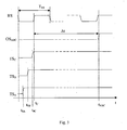
- Figures 1 and 2 show, in simplified form, what mentioned above in case of two different time intervals, ⁇ t 1CPU and ⁇ t 2CPU , respectively, necessary for allowing the probe logic circuits to complete the required checking operations. More specifically, the figures show the trend - as a function of time t in the time interval between an instant t 0 (moment when contact occurs) and an instant t 1 (moment of transmission of the output signal) - of a reference signal RS, of a signal CPUA representative of the operations carried out by the logic circuits after contact, of an output signal OS 01 and of a contact signal TS 01 .
- the output signal OS 01 of both figures 1 and 2 is generated and transmitted at the instant t 1 after an identical delay ⁇ t 01 starting from the instant to regardless of the time interval ⁇ t 1CPU and ⁇ t 2CPU of the signal CPUA, i.e. the duration of the operations performed by the probe logic circuits in the course of the checking.
- the accuracy of the delay ⁇ t 01 generated between contact and transmission of the associated signal is strictly correlated to the stability of the frequency of the reference signal and to the short activation (or "start-up") time of the clock, defined as the time necessary for the clock to activate further to an edge of the contact signal, or other suitable signal.
- a different method substantially alike the method mentioned at the beginning of the description, foresees the activation of the crystal resonator at the start of the checking (before contact occurs), while just the counter is activated at the edge of the contact signal.
- the selection of the frequency of the reference signal is critical because the oscillation period defines the resolution that would be obtained in the amount of time delay between the instant of contact and the start of the transmission of the output signal.
- the counter cannot activate at any whatever moment, but must wait for a change of state, in other words an edge, typically the rising edge, of the reference signal.
- FIG. 3 where a relatively slow clock (that generates a reference signal RS with a relatively long period T RS ) is shown and three contact signals TS A , TS B , TS C are represented at three different moments of contact t 0A , t 0B , t 0C ; for all the signals TS A , TS B , TS C the count always starts at a time t c at the same first rising edge of the reference signal RS subsequent to contact, so that their original time separation no longer exists and an output signal OS ABC is generated and transmitted for all signals at the same time t ABC , exactly after an identical delay ⁇ t from the instant t c .
- European patent application EP-A-0826201 suggests to slightly alter (to increase or to decrease) the period of the output signal representative of contact, so as to keep the delay between contact and the end of the transmission of the output signal constant.
- a typically requested resolution is in the order of 1 ⁇ s, that corresponds to a minimum frequency of the reference signal of 1 MHz. Operating at similar frequencies is quite problematic in a battery-powered system; owing to the high and constant consumption of current of the associated clock.
- Detecting signals are wireless transmitted to a receiver and forwarded by the latter to a CNC apparatus of a machining tool with a predetermined delay in order to compensate timing errors of different received signals.
- the delay is compensated in the CNC by means of a known correcting value.
- US-A-4864294 does not mention any delays in the wireless transmission from the detecting head to the receiver, nor systems or methods for obtaining such delays in an extremely accurate and repeatable way.
- European patent application EP-A-0903655 describes a communication assembly for a control system, where timing information for sensor data signals (e.g. output by a temperature or a pressure sensor, or a tachometer) is provided.
- a sensor time-stamp is generated in a sensor node of a network communication path substantially contemporaneously with the sampling of the sensor data signal, and transmitted through a controller to an actuator node of the same path, sensor and actuator nodes including mutually synchronised clock circuits.
- An object of the present invention is to provide a system and a method for the wireless transmission of signals that enable to achieve high standards of performance in terms of transmission accuracy and/or repeatability, more specifically with regard to the delay between the instant when a significative event occurs and the start of the transmission of signals indicative of such event, and concurrently low energy consumption.
- This and other objects are attained by a system according to claim 1 and a method according to claim 12.
- a system and a method according to the invention enable to minimize the consumption of electric energy and thus utilize, in an advantageous way and at a high standard of performance, battery-powered contact detecting probes for checking mechanical parts, for example mechanical pieces and tools.
- a system for the wireless transmission of signals according to the invention can be utilized, for example, in contact detecting probes for numerical control machine tools, and includes circuit systems and/or component parts for receiving a signal indicative of an event, for example a contact signal indicative of contact occurring between the probe and a piece to be checked, at least two generators of reference signals, at least one of the latters being periodic, processing means including at least one counter for counting a preset number of cycles of at least one of the reference signals and a transmitter of output signals indicative of the event under consideration.
- the processing means generate two distinct delays that, when combined, define a particularly accurate and repeatable overall delay between event under consideration and start of the transmission of the associated output signal. More specifically, a first generator is highly stable and is utilized for generating most of the overall delay, while a second generator is relatively less accurate, though it has short start-up times and is utilized for generating just a relatively short interval of the overall delay.
- the first generator that generates a periodic reference signal
- the second generator that generates a second reference signal
- an event for example contact between a contact detecting probe and a piece, precisely when a signal indicates such contact.
- the processing means check the value of a parameter of the second reference signal between the activation of the second generator (which corresponds with accurate approximation to the instant when contact occurs) and, for example, the first subsequent rising edge of the first reference signal. It should be realized that the check is carried out for a short time interval, more specifically shorter than the period of the first reference signal. At the first subsequent rising edge of the first reference signal, the check of the parameter of the second reference signal is stopped and a current value of the parameter is memorized. At this point the processing means count, by means of a counter, a preset number of cycles of the first reference signal and other circuits and/or devices of the system, for example the second generator, can be advantageously turned off.
- the second generator is activated again and the processing means continue the check of the parameter of the second reference signal starting from the previously detected value up to a preset value.
- an output signal indicative of contact between the probe and the piece can be wirelessly transmitted.
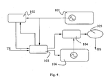
- a transmission system includes a first generator of synchronism pulses, or first, low-frequency clock 101.
- the low-frequency clock 101 that generates a first periodic reference signal at a first, low frequency, can be implemented, for example, by means of a quartz crystal oscillator that, as known, has characteristics according to which the lower its frequency, the lesser the electric energy consumption.
- a quartz oscillator oscillating at a frequency of 32768 Hz can operate at an average electric current consumption in the order of 1 ⁇ A.
- An output of the low-frequency clock 101 is connected to processing means, that include a first low-frequency counter 102, a second, high frequency counter 104 and a logic unit 103.
- the output of the low frequency clock 101 is connected to suitable inputs of the first low frequency counter 102 and of the logic unit 103.
- the logic unit 103 and the low frequency clock 101 are always power supplied.
- the logic unit 103 also receives in input a signal representative of an event, for example a contact signal TS indicative of contact between a contact detecting probe and a piece to be checked, and an output of the low frequency counter 102.
- the logic unit 103 has three outputs: a first output towards the low frequency counter 102, a second output towards a second generator of synchronism pulses, or second high frequency clock 106, and a third output towards the second, high frequency counter 104.
- the high frequency clock 106 generates a second periodic reference signal at a second, high frequency and includes logic activation circuits.
- the logic unit 103 zero sets the high frequency counter 104, the latter also receives, at a suitable input, an output of the high frequency clock 106 and provides a signal for controlling a known-type transmitter 105 to transmit an output signal OS representative of contact.
- the high frequency clock 106 can be implemented in many ways, for example by means of a high frequency oscillator, provided the latter has a short start-up time. In other words, the long term stability feature can be set aside to the advantage of a shorter start-up time.
- the reason for which it is possible to set aside the long term stability of the high frequency clock 106, tolerate noises and even high phase distortions, is that the high frequency clock 106 has the sole task of generating pulses for a very short time interval, advantageously in the order of the period of the low frequency clock 101, as hereinafter described.
- the time error that the high frequency clock 106 could accumulate is in any case limited and practically of no influence over the overall delay.
- the error caused by the high frequency clock 106 in a whole period of the signal generated by the low frequency clock 101 is approximately 1 ⁇ s.
- a quartz crystal low frequency oscillator operating at 32768 Hz a resolution of 1 ⁇ s or 0.5 ⁇ s in the transmission delay between the contact signal TS and the start of the transmission of the output signal OS can be achieved by implementing the high frequency clock 106 by means of an oscillator operating at 1 or 2 MHz, respectively.
- the clocks 101 and 106, the counters 102 and 104 and the logic unit 103 can be appropriately integrated in a logic of the CMOS static low consumption type or implemented by means of other analogous low consumption technology.
- the transmission system illustrated in figure 4 can be advantageously utilized by a method according to the invention, now described with reference to figure 5 , for transmitting an output signal indicative, for example, of contact between a feeler of a contact detecting probe and a piece to be checked with a constant and repeatable delay between the instant when contact occurs and the start of the transmission of the output signal.
- the method further includes the steps of verifying whether contact between the probe and the piece has occurred (step 120 ), and "awaking" the system further to contact for placing the latter in a fully operative mode (step 130 ). More specifically when contact occurs, the logic unit 103 controls, by means of the logic activation circuits, the turning on of the high frequency clock 106 for generating the second high frequency reference signal and concurrently the zero setting of the high frequency counter 104.
- the high frequency counter 104 starts a check of a parameter of the second reference signal, more specifically a count of the number of cycles of the high frequency reference signal (step 140 ) between the instant of contact and a rising edge of the low frequency clock 101, advantageously the first subsequent rising edge. At every count of the high frequency counter 104, the presence, or not, of the first subsequent rising edge of the low frequency reference signal is verified (step 150 ) .
- a number P of cycles of the high frequency reference signal up to here counted is memorized by means of the logic unit 103 (step 160), the high frequency clock 106 can be advantageously deactivated (step 170), and the low frequency counter 102 is zero-set while the count of the cycles of the low frequency reference signal is activated (step 180).
- the steps 160, 170 and 180 substantially take place at the same instant, at the first rising edge of the low frequency signal subsequent to contact. It should be realized that the low frequency counter 102 is driven by a very stable source (the low frequency clock 101 ) and thus can accurately count for time intervals in the order of tens of milliseconds.
- the other devices/circuits can be advantageously turned off, more specifically (as indicated at step 170 ) the high frequency clock 106, that, as previously stated, is particularly costly in terms of energy consumption. In this way the consumption of electric current can be reduced to a minimum.
- the count of the number of cycles of the low frequency reference signal continues up to a preset number Q LF (step 190 ); once the latter number has been reached, the logic unit 103 freezes the low frequency counter 102 and turns on again the high frequency clock 106 (in the event the clock had previously been turned off) by means of the logic activation circuits (step 200 ).
- the high frequency counter 104 continues the count of the number of cycles of the high frequency reference signal, starting from the previously memorized number P (step 210 ).
- the high frequency clock 106 can be turned off and the high frequency counter 104 frozen, and the system transmits an output signal indicative of contact between the probe and the piece (step 230 ).
- the high frequency counter 104 In order to eliminate any dependency of the delay generated by the high frequency counter 104 on the fraction of period elapsing between contact and the first rising edge of the low frequency reference signal, the high frequency counter 104 must be programmed to count up to a preset number Q HF of cycles that satisfy the following condition: Q HF > T LF / T HF + 1 where T LF and T HF are the periods of the low frequency reference signal and of the high frequency reference signal, respectively.
- Q HF can advantageously take the minimum value.
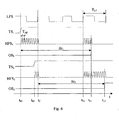
- Figure 6 shows, in simplified form, the trend as a function of time of two output signals OS 1 and OS 2 generated by the system of figure 4 utilizing the method of figure 5 , in the case of two contact signals TS 1 and TS 2 generated at two different moments t 01 and t 02 , respectively, but in any case within an identical period T LF of the low frequency reference signal generated by the first low frequency clock 101 and identified by reference LFS in figure 6 .
- Q LF and Q HF are constant and Q HF is, for example, 12.
- the second high frequency clock 106 has a known start-up time ⁇ t HF . It should be realized that such start-up time ⁇ t HF is extremely limited and in any case negligible (for this reason not shown in figure 6 ).
- the logic unit 103 activates, by means of the logic activation circuits, the high frequency clock 106 that generates a signal HFS 1 after the start-up time ⁇ t HF .
- the counter 104 starts to count the cycles of the signal HFS 1 .
- the logic unit 103 stops the count of the counter 104, freezes the number P up to that moment counted (in the example of figure 6 it is 8) and activates the low frequency counter 102 that counts a preset number of cycles Q LF of the signal LFS (that define a first delay ⁇ TL ), up to a time t D .
- the high frequency clock 106 can be turned off.
- the logic unit 103 activates again the high frequency clock 106 by means of the logic activation circuits (the introduced delay is equal to the start-up time ⁇ t HF ) and the high frequency counter 104 restarts counting the cycles of the signal HFS 1 , from the previously memorized (8) number P up to the value Q HF (12), i.e. in the specific case, 4.
- An output signal OS 1 is sent at an instant t 11 at the end of the count of the counter 104, with a total transmission delay ⁇ t 1 between the instant of contact t 01 and the instant t 11 equal to 12 (namely 8 + 4) cycles of the signal HFS 1 (that altogether define a second delay ⁇ TH ) and of the first delay ⁇ TL defined by the Q LF cycles of the signal LFS, besides twice the start-up time ⁇ t HF of the high frequency clock 106 (negligible, as previously stated). It should be realized that, according to the previously mentioned condition (1), the duration in time of the second delay ⁇ TH (that is Q HF T HF ) is longer than that of a period (T LF ) of the first reference signal LFS.
- the logic unit 103 activates, by means of the logic activation circuits, the high frequency clock 106, that generates, analogously to the previous case, a signal HFS 2 , after a start-up time ⁇ t HF .
- the high frequency clock 106 can be turned off while the low frequency counter 102 counts the Q LF cycles of the signal LFS (the first delay ⁇ TL ) up to the time t D , at the end of which the high frequency clock 106 is activated again (the introduced delay is always equal to the start-up time ⁇ t HF ) and the high frequency counter 104 counts ( QHF P ) cycles of the signal HFS 2 .
- Q HF - P 10
- a second output signal OS 2 is transmitted.
- the delay ⁇ t 2 is equal to 12 (namely 2 + 10) cycles of the signal HFS 2 (the second delay ATH ) and the Q LF cycles of the signal LFS (the first delay ATL ), besides twice the start-up time ⁇ t HF of the high frequency clock 106 (negligible, as previously stated).
- the delay ⁇ t 2 is substantially equal to the delay ⁇ t 1 .
- there are utilized commercial component parts like a quartz crystal oscillator at 32768 Hz (approximately 30.5 ⁇ s period) as first low frequency clock 101 and a ring oscillator RC at 1 MHz (1 ⁇ s period) with 2 ⁇ s start-up time as second high frequency clock 106.
- the high frequency clock 106 and the high frequency counter 104 of the transmission system shown in figure 4 have been replaced with analogic component parts, so as to implement a transmission system according to the invention of analogic/digital type.
- the transmission system of analogic/digital type according to the invention and its operation are hereinafter described with reference to figures 7 and 8 , in which references like those of figures 4 and 6 are used to denote like or similar component parts or signals.
- the transmission system of figure 7 includes a first generator of synchronism pulses, or first low frequency clock 101 that generates a first low frequency reference signal LFS and is connected to processing means including a low frequency counter 102, a logic unit 109, a selector switch 107 and a comparator 96.
- the low frequency clock 101 is connected to suitable inputs of the low frequency counter 102 for counting a preset number Q LF of cycles of the signal LFS and to suitable inputs of the logic unit 109, which further receives at its input an output of the low frequency counter 102, a signal TS 3 representative of an event, for example contact between a contact detecting probe and a piece to be checked, and a signal representative of an output signal of the comparator 96.
- the contact detecting probe starts a checking cycle
- the low frequency clock 101 is power supplied (as well as the logic unit 109 ) for generating the reference signal LFS.
- the logic unit 109 has two outputs, a first output connected to the low frequency counter 102 and a second output connected to the selector switch 107 that defines three possible connections for a capacitor 99 with a first plate 90 typically connected to ground.
- the selector switch 107 connects (for example in series) the capacitor 99 to a resistance 98.
- the resistance 98 and the capacitor 99 are power supplied by a first voltage generator 97.
- the first voltage generator 97, the resistance 98 and the capacitor 99 implement a circuit RC with known charge trend that defines a second generator for generating a second reference signal.
- the circuit RC can be replaced with a reactive circuit including, for example, an impedance.
- the generated signal is an analogic signal representative of a magnitude variable in a known way. More specifically, with regard to the circuit RC shown in figure 7 , the generated analogic signal is representative of a voltage, and the voltage is the very parameter whose value is to be checked.
- a contact signal TS 3 arrives at the logic unit 109 and the latter controls the selector switch 107 to switch to the first position A.
- the first voltage generator 97 starts to charge the capacitor 99 up to the moment when the logic unit 109 detects a rising edge of the signal LFS, advantageously the first subsequent rising edge at a time t c .
- the logic unit 109 controls the selector switch 107 to switch to a second position B in which the capacitor 99 is electrically insulated, hence the charging of the capacitor 99 is interrupted at a specific voltage value V 1 that will depend on the time interval between the event ( t 03 ) and the first subsequent rising edge of the signal LFS ( t c ).
- the reference VS indicates the second reference signal defined by the trend of the voltage value at the ends of the capacitor 99 as a function of time.
- the low frequency counter 102 counts a preset number Q LF of cycles of the signal LFS starting from the first rising edge subsequent to contact.
- the logic unit 109 controls the selector switch 107 to switch back to the first position A and the capacitor 99 restarts charging and the voltage at its ends increases starting from the previously reached value V 1 .
- a non-inverting input of the comparator 96 is connected to an end of the capacitor 99, while an inverting input of the same comparator 96 is connected to a second voltage generator 95 at reference voltage V ref . More specifically, regardless of the position of the selector switch 107, when the voltage at the ends of the capacitor 99 reaches a value V 2 equal to (or above) the reference voltage V ref , the comparator 96 sends an output, non-null signal. On the contrary, when the voltage at the ends of the capacitor 99 is less than the reference voltage V ref , the output of the comparator 96 is null.
- the logic unit 109 controls the selector switch 107 to switch to a third position C in which the capacitor 99 is discharged, for example, by connecting to ground a second plate 91 too.
- interval ⁇ t 3 is formed by Q LF periods of the signal LFS (that define, as in the case shown in figures 4 and 6 , a first delay ⁇ TL ) and by the amount of time it takes the capacitor to charge from a null value to the value V 1 (at the first rising edge of the signal LFS ) and from the value V 1 to the value V 2 (equal to the reference voltage V ref of the comparator 96 ). It should also be noted how the amount of time necessary for charging the capacitor 99 from a null value to the value V 2 (time that defines a second delay ⁇ TV ) does not depend on the moment when the event occurs with respect to the first rising edge of the signal LFS, but only on the features of the RC circuit.
- V 2 ( V ref ) is chosen and preset in a way that, as occurs in the embodiment of figure 4 , the second delay ⁇ TV is (only by a small amount) longer than the period T LF of the first reference signal LFS.
- a system and a method according to the invention can be advantageously implemented in contact detecting probes mounted on machine tools for checking mechanical pieces before, during and after the machining.
- Figure 9 schematically illustrates a system for detecting the position or the dimensions of a mechanical piece 3 mounted on a machine tool 6, with a checking probe, for example a contact detecting probe 1 with a movable arm 5 carrying a feeler 8.
- a detecting device 2 of a known type provides a contact signal when, further to mutual displacements between the probe 1 and the piece 3, the feeler 8 contacts a surface of the piece 3.
- a transmission system 4 with the features of the transmission systems so far described and illustrated with reference to figures 4-6 or 7-8 is connected (in a known way) to the detecting device 2, receives the contact signal and wirelessly transmits signals representative of contact to a receiver 7 located at a distance from the probe 1 and connected, by means of an interface device 9, to a numerical control unit 11 of the machine tool 6.
- the numerical control unit obtains information regarding the position of the surfaces of the piece 3.
- the wirelessly transmitted signals can be, for example, of the optical, or radio-frequency type and utilize known technology, like Bluetooth®, WiFi® and UWB ("Ultra-Wideband"). Furthermore, there can be foreseen devices for wireless transmitting signals from the receiver 7 to the probe 1, for example for the activation/deactivation of on-board probe circuits or for programming determined parameters, in a known way and that do not directly regard the present invention.
- a transmission system according to the invention can be utilized whenever there be a need of an accurate, repeatable and low energy consumption system for the transmission of signals representative of events.
Landscapes
- Engineering & Computer Science (AREA)
- Computer Networks & Wireless Communication (AREA)
- Signal Processing (AREA)
- Measurement Of Length, Angles, Or The Like Using Electric Or Magnetic Means (AREA)
- Arrangements For Transmission Of Measured Signals (AREA)
- Selective Calling Equipment (AREA)
- Transmission And Conversion Of Sensor Element Output (AREA)
- Tests Of Electronic Circuits (AREA)
- A Measuring Device Byusing Mechanical Method (AREA)
- Machine Tool Sensing Apparatuses (AREA)
- Measurement Of Resistance Or Impedance (AREA)
Applications Claiming Priority (2)
| Application Number | Priority Date | Filing Date | Title |
|---|---|---|---|
| IT000031A ITBO20060031A1 (it) | 2006-01-18 | 2006-01-18 | Sistema e metodo di trasmissione a distanza di segnali via etere per sonde di controllo |
| PCT/EP2007/050419 WO2007082892A1 (en) | 2006-01-18 | 2007-01-16 | Timing measurement for checking probes |
Publications (2)
| Publication Number | Publication Date |
|---|---|
| EP1982488A1 EP1982488A1 (en) | 2008-10-22 |
| EP1982488B1 true EP1982488B1 (en) | 2011-06-15 |
Family
ID=37969858
Family Applications (1)
| Application Number | Title | Priority Date | Filing Date |
|---|---|---|---|
| EP07703926A Not-in-force EP1982488B1 (en) | 2006-01-18 | 2007-01-16 | Timing measurement for contact probes |
Country Status (10)
| Country | Link |
|---|---|
| US (1) | US8107554B2 (ja) |
| EP (1) | EP1982488B1 (ja) |
| JP (1) | JP5191904B2 (ja) |
| KR (1) | KR101293131B1 (ja) |
| CN (1) | CN101375568B (ja) |
| AT (1) | ATE513400T1 (ja) |
| CA (1) | CA2637732C (ja) |
| ES (1) | ES2366744T3 (ja) |
| IT (1) | ITBO20060031A1 (ja) |
| WO (1) | WO2007082892A1 (ja) |
Families Citing this family (10)
| Publication number | Priority date | Publication date | Assignee | Title |
|---|---|---|---|---|
| JP5163901B2 (ja) * | 2009-01-05 | 2013-03-13 | ブラザー工業株式会社 | 工作機械 |
| US8133446B2 (en) * | 2009-12-11 | 2012-03-13 | Uop Llc | Apparatus for producing hydrocarbon fuel |
| US9074143B2 (en) * | 2009-12-11 | 2015-07-07 | Uop Llc | Process for producing hydrocarbon fuel |
| US8193401B2 (en) * | 2009-12-11 | 2012-06-05 | Uop Llc | Composition of hydrocarbon fuel |
| US20120197570A1 (en) * | 2011-01-27 | 2012-08-02 | Mehran Ramezani | Measurement of Parameters Within an Integrated Circuit Chip Using a Nano-Probe |
| DE102011076504A1 (de) * | 2011-05-26 | 2012-11-29 | Dr. Johannes Heidenhain Gmbh | Tastsystem und Verfahren zum Betrieb eines Tastsystems |
| JP6106963B2 (ja) * | 2012-06-20 | 2017-04-05 | 富士電機株式会社 | スイッチング電源装置 |
| KR20190110733A (ko) * | 2018-03-21 | 2019-10-01 | 에스케이하이닉스 주식회사 | 클럭 신호에 동기하여 신호를 전송 및 수신하는 반도체 장치 |
| JP7067514B2 (ja) * | 2018-03-29 | 2022-05-16 | ブラザー工業株式会社 | 工作機械 |
| CN111490867B (zh) * | 2020-04-26 | 2021-02-12 | 杭州锐讯科技有限公司 | 一种面向分布式应用的采样时钟同步系统及方法 |
Family Cites Families (9)
| Publication number | Priority date | Publication date | Assignee | Title |
|---|---|---|---|---|
| US4509266A (en) | 1982-06-14 | 1985-04-09 | Gte Valeron Corporation | Touch probe |
| JPH0765883B2 (ja) | 1986-06-05 | 1995-07-19 | 宣夫 福久 | 無線送受信器を有する位置検出装置 |
| US5483201A (en) * | 1993-09-30 | 1996-01-09 | At&T Corp. | Synchronization circuit using a high speed digital slip counter |
| US5473533A (en) * | 1993-12-02 | 1995-12-05 | Best Power Technology, Incorporated | Method and apparatus for efficient phase and frequency coherence locking optimized for digital systems |
| IT1279590B1 (it) * | 1995-05-11 | 1997-12-16 | Marposs Spa | Sistema e metodo di trasmissione di segnali via etere fra una testa di controllo e un ricevitore remoto |
| JP2900836B2 (ja) * | 1995-05-26 | 1999-06-02 | 松下電器産業株式会社 | 電子走査式超音波診断装置 |
| DE19610626C2 (de) * | 1996-03-19 | 2003-01-23 | Bosch Gmbh Robert | Nachlauferfassung von elektrischen Verstellmotoren |
| US5831485A (en) * | 1997-09-04 | 1998-11-03 | Tektronix, Inc. | Method and apparatus for producing a temperature stable frequency using two oscillators |
| US6173207B1 (en) | 1997-09-22 | 2001-01-09 | Agilent Technologies, Inc. | Real-time control system with non-deterministic communication |
-
2006
- 2006-01-18 IT IT000031A patent/ITBO20060031A1/it unknown
-
2007
- 2007-01-16 US US12/087,727 patent/US8107554B2/en not_active Expired - Fee Related
- 2007-01-16 CA CA2637732A patent/CA2637732C/en not_active Expired - Fee Related
- 2007-01-16 EP EP07703926A patent/EP1982488B1/en not_active Not-in-force
- 2007-01-16 CN CN2007800032886A patent/CN101375568B/zh not_active Expired - Fee Related
- 2007-01-16 JP JP2008550749A patent/JP5191904B2/ja not_active Expired - Fee Related
- 2007-01-16 KR KR1020087019601A patent/KR101293131B1/ko not_active IP Right Cessation
- 2007-01-16 WO PCT/EP2007/050419 patent/WO2007082892A1/en active Application Filing
- 2007-01-16 AT AT07703926T patent/ATE513400T1/de not_active IP Right Cessation
- 2007-01-16 ES ES07703926T patent/ES2366744T3/es active Active
Also Published As
| Publication number | Publication date |
|---|---|
| US20090122934A1 (en) | 2009-05-14 |
| KR20080089634A (ko) | 2008-10-07 |
| CA2637732C (en) | 2013-06-25 |
| EP1982488A1 (en) | 2008-10-22 |
| JP5191904B2 (ja) | 2013-05-08 |
| CA2637732A1 (en) | 2007-07-26 |
| ATE513400T1 (de) | 2011-07-15 |
| JP2009523620A (ja) | 2009-06-25 |
| ES2366744T3 (es) | 2011-10-25 |
| ITBO20060031A1 (it) | 2007-07-19 |
| US8107554B2 (en) | 2012-01-31 |
| CN101375568A (zh) | 2009-02-25 |
| WO2007082892A1 (en) | 2007-07-26 |
| CN101375568B (zh) | 2011-08-17 |
| KR101293131B1 (ko) | 2013-08-12 |
Similar Documents
| Publication | Publication Date | Title |
|---|---|---|
| EP1982488B1 (en) | Timing measurement for contact probes | |
| US5884410A (en) | Sensing system for coordinate measuring equipment | |
| EP1585223B1 (en) | Method and circuit for determining a slow clock calibration factor | |
| CN104215961A (zh) | 雷达装置及雷达性能计测方法 | |
| US10901064B2 (en) | Ultrasonic beacon tracking | |
| JP3647464B2 (ja) | 測定ヘッドとリモート受信機との間で信号を無線伝送するための装置および方法 | |
| US6670800B2 (en) | Timing variation measurements | |
| CN100451670C (zh) | 电池容量检测设备和检测方法 | |
| US10274601B2 (en) | Communications system | |
| US20120306580A1 (en) | Correction of Low Accuracy Clock | |
| CN103744284B (zh) | 一种用于输电线参数测量的两端时间同步触发系统及方法 | |
| CN105629329B (zh) | 校准接近检测传感器和关联传感器的待机持续时间的方法 | |
| WO2000058794A1 (fr) | Dispositif electronique, dispositif de reglage externe de dispositif electronique et procede de reglage de dispositif electronique | |
| US6754513B1 (en) | Method and configuration for identification of a mobile station associated with a base station | |
| US6369563B1 (en) | Method for high resolution measurement of a position | |
| US6148055A (en) | Counter and a revolution stop detection apparatus using the counter | |
| JP2004530120A (ja) | 位置測定装置を作動させる方法及びこの方法に適した位置測定装置 | |
| JP6296831B2 (ja) | 電子時計および歩度測定器 | |
| US10134275B2 (en) | Monitoring vehicle parking occupancy | |
| JP7432639B2 (ja) | 可搬型測定装置およびホールドオーバー制御方法 | |
| JPH11281778A (ja) | 電源同期時計 | |
| JP2023101481A (ja) | 集積回路 | |
| JPH10319112A (ja) | 電波高度計 | |
| US20150222965A1 (en) | Receiver circuit and method for its operation | |
| JP2005172722A (ja) | 時刻情報パルス発生装置 |
Legal Events
| Date | Code | Title | Description |
|---|---|---|---|
| PUAI | Public reference made under article 153(3) epc to a published international application that has entered the european phase |
Free format text: ORIGINAL CODE: 0009012 |
|
| 17P | Request for examination filed |
Effective date: 20080818 |
|
| AK | Designated contracting states |
Kind code of ref document: A1 Designated state(s): AT BE BG CH CY CZ DE DK EE ES FI FR GB GR HU IE IS IT LI LT LU LV MC NL PL PT RO SE SI SK TR |
|
| 17Q | First examination report despatched |
Effective date: 20090831 |
|
| GRAP | Despatch of communication of intention to grant a patent |
Free format text: ORIGINAL CODE: EPIDOSNIGR1 |
|
| RTI1 | Title (correction) |
Free format text: TIMING MEASUREMENT FOR CONTACT PROBES |
|
| DAX | Request for extension of the european patent (deleted) | ||
| GRAS | Grant fee paid |
Free format text: ORIGINAL CODE: EPIDOSNIGR3 |
|
| GRAA | (expected) grant |
Free format text: ORIGINAL CODE: 0009210 |
|
| AK | Designated contracting states |
Kind code of ref document: B1 Designated state(s): AT BE BG CH CY CZ DE DK EE ES FI FR GB GR HU IE IS IT LI LT LU LV MC NL PL PT RO SE SI SK TR |
|
| REG | Reference to a national code |
Ref country code: CH Ref legal event code: EP Ref country code: GB Ref legal event code: FG4D |
|
| REG | Reference to a national code |
Ref country code: IE Ref legal event code: FG4D |
|
| REG | Reference to a national code |
Ref country code: DE Ref legal event code: R096 Ref document number: 602007015219 Country of ref document: DE Effective date: 20110721 |
|
| REG | Reference to a national code |
Ref country code: SE Ref legal event code: TRGR |
|
| REG | Reference to a national code |
Ref country code: NL Ref legal event code: VDEP Effective date: 20110615 |
|
| REG | Reference to a national code |
Ref country code: ES Ref legal event code: FG2A Ref document number: 2366744 Country of ref document: ES Kind code of ref document: T3 Effective date: 20111025 |
|
| PG25 | Lapsed in a contracting state [announced via postgrant information from national office to epo] |
Ref country code: LT Free format text: LAPSE BECAUSE OF FAILURE TO SUBMIT A TRANSLATION OF THE DESCRIPTION OR TO PAY THE FEE WITHIN THE PRESCRIBED TIME-LIMIT Effective date: 20110615 |
|
| PG25 | Lapsed in a contracting state [announced via postgrant information from national office to epo] |
Ref country code: AT Free format text: LAPSE BECAUSE OF FAILURE TO SUBMIT A TRANSLATION OF THE DESCRIPTION OR TO PAY THE FEE WITHIN THE PRESCRIBED TIME-LIMIT Effective date: 20110615 Ref country code: CY Free format text: LAPSE BECAUSE OF FAILURE TO SUBMIT A TRANSLATION OF THE DESCRIPTION OR TO PAY THE FEE WITHIN THE PRESCRIBED TIME-LIMIT Effective date: 20110615 Ref country code: GR Free format text: LAPSE BECAUSE OF FAILURE TO SUBMIT A TRANSLATION OF THE DESCRIPTION OR TO PAY THE FEE WITHIN THE PRESCRIBED TIME-LIMIT Effective date: 20110916 Ref country code: FI Free format text: LAPSE BECAUSE OF FAILURE TO SUBMIT A TRANSLATION OF THE DESCRIPTION OR TO PAY THE FEE WITHIN THE PRESCRIBED TIME-LIMIT Effective date: 20110615 Ref country code: SI Free format text: LAPSE BECAUSE OF FAILURE TO SUBMIT A TRANSLATION OF THE DESCRIPTION OR TO PAY THE FEE WITHIN THE PRESCRIBED TIME-LIMIT Effective date: 20110615 Ref country code: LV Free format text: LAPSE BECAUSE OF FAILURE TO SUBMIT A TRANSLATION OF THE DESCRIPTION OR TO PAY THE FEE WITHIN THE PRESCRIBED TIME-LIMIT Effective date: 20110615 |
|
| PG25 | Lapsed in a contracting state [announced via postgrant information from national office to epo] |
Ref country code: NL Free format text: LAPSE BECAUSE OF FAILURE TO SUBMIT A TRANSLATION OF THE DESCRIPTION OR TO PAY THE FEE WITHIN THE PRESCRIBED TIME-LIMIT Effective date: 20110615 Ref country code: BE Free format text: LAPSE BECAUSE OF FAILURE TO SUBMIT A TRANSLATION OF THE DESCRIPTION OR TO PAY THE FEE WITHIN THE PRESCRIBED TIME-LIMIT Effective date: 20110615 |
|
| PG25 | Lapsed in a contracting state [announced via postgrant information from national office to epo] |
Ref country code: PT Free format text: LAPSE BECAUSE OF FAILURE TO SUBMIT A TRANSLATION OF THE DESCRIPTION OR TO PAY THE FEE WITHIN THE PRESCRIBED TIME-LIMIT Effective date: 20111017 Ref country code: IS Free format text: LAPSE BECAUSE OF FAILURE TO SUBMIT A TRANSLATION OF THE DESCRIPTION OR TO PAY THE FEE WITHIN THE PRESCRIBED TIME-LIMIT Effective date: 20111015 Ref country code: EE Free format text: LAPSE BECAUSE OF FAILURE TO SUBMIT A TRANSLATION OF THE DESCRIPTION OR TO PAY THE FEE WITHIN THE PRESCRIBED TIME-LIMIT Effective date: 20110615 |
|
| PG25 | Lapsed in a contracting state [announced via postgrant information from national office to epo] |
Ref country code: PL Free format text: LAPSE BECAUSE OF FAILURE TO SUBMIT A TRANSLATION OF THE DESCRIPTION OR TO PAY THE FEE WITHIN THE PRESCRIBED TIME-LIMIT Effective date: 20110615 Ref country code: SK Free format text: LAPSE BECAUSE OF FAILURE TO SUBMIT A TRANSLATION OF THE DESCRIPTION OR TO PAY THE FEE WITHIN THE PRESCRIBED TIME-LIMIT Effective date: 20110615 Ref country code: RO Free format text: LAPSE BECAUSE OF FAILURE TO SUBMIT A TRANSLATION OF THE DESCRIPTION OR TO PAY THE FEE WITHIN THE PRESCRIBED TIME-LIMIT Effective date: 20110615 |
|
| PLBE | No opposition filed within time limit |
Free format text: ORIGINAL CODE: 0009261 |
|
| STAA | Information on the status of an ep patent application or granted ep patent |
Free format text: STATUS: NO OPPOSITION FILED WITHIN TIME LIMIT |
|
| 26N | No opposition filed |
Effective date: 20120316 |
|
| PG25 | Lapsed in a contracting state [announced via postgrant information from national office to epo] |
Ref country code: DK Free format text: LAPSE BECAUSE OF FAILURE TO SUBMIT A TRANSLATION OF THE DESCRIPTION OR TO PAY THE FEE WITHIN THE PRESCRIBED TIME-LIMIT Effective date: 20110615 |
|
| REG | Reference to a national code |
Ref country code: DE Ref legal event code: R097 Ref document number: 602007015219 Country of ref document: DE Effective date: 20120316 |
|
| PG25 | Lapsed in a contracting state [announced via postgrant information from national office to epo] |
Ref country code: MC Free format text: LAPSE BECAUSE OF NON-PAYMENT OF DUE FEES Effective date: 20120131 |
|
| REG | Reference to a national code |
Ref country code: IE Ref legal event code: MM4A |
|
| PG25 | Lapsed in a contracting state [announced via postgrant information from national office to epo] |
Ref country code: IE Free format text: LAPSE BECAUSE OF NON-PAYMENT OF DUE FEES Effective date: 20120116 |
|
| PG25 | Lapsed in a contracting state [announced via postgrant information from national office to epo] |
Ref country code: BG Free format text: LAPSE BECAUSE OF FAILURE TO SUBMIT A TRANSLATION OF THE DESCRIPTION OR TO PAY THE FEE WITHIN THE PRESCRIBED TIME-LIMIT Effective date: 20110915 |
|
| PG25 | Lapsed in a contracting state [announced via postgrant information from national office to epo] |
Ref country code: TR Free format text: LAPSE BECAUSE OF FAILURE TO SUBMIT A TRANSLATION OF THE DESCRIPTION OR TO PAY THE FEE WITHIN THE PRESCRIBED TIME-LIMIT Effective date: 20110615 |
|
| PG25 | Lapsed in a contracting state [announced via postgrant information from national office to epo] |
Ref country code: LU Free format text: LAPSE BECAUSE OF NON-PAYMENT OF DUE FEES Effective date: 20120116 |
|
| PG25 | Lapsed in a contracting state [announced via postgrant information from national office to epo] |
Ref country code: HU Free format text: LAPSE BECAUSE OF FAILURE TO SUBMIT A TRANSLATION OF THE DESCRIPTION OR TO PAY THE FEE WITHIN THE PRESCRIBED TIME-LIMIT Effective date: 20070116 |
|
| REG | Reference to a national code |
Ref country code: FR Ref legal event code: PLFP Year of fee payment: 9 |
|
| PGFP | Annual fee paid to national office [announced via postgrant information from national office to epo] |
Ref country code: CZ Payment date: 20141219 Year of fee payment: 9 |
|
| PGFP | Annual fee paid to national office [announced via postgrant information from national office to epo] |
Ref country code: ES Payment date: 20150122 Year of fee payment: 9 |
|
| PGFP | Annual fee paid to national office [announced via postgrant information from national office to epo] |
Ref country code: SE Payment date: 20150122 Year of fee payment: 9 Ref country code: FR Payment date: 20150119 Year of fee payment: 9 |
|
| REG | Reference to a national code |
Ref country code: FR Ref legal event code: ST Effective date: 20160930 |
|
| PG25 | Lapsed in a contracting state [announced via postgrant information from national office to epo] |
Ref country code: CZ Free format text: LAPSE BECAUSE OF NON-PAYMENT OF DUE FEES Effective date: 20160116 Ref country code: FR Free format text: LAPSE BECAUSE OF NON-PAYMENT OF DUE FEES Effective date: 20160201 Ref country code: SE Free format text: LAPSE BECAUSE OF NON-PAYMENT OF DUE FEES Effective date: 20160117 |
|
| PGFP | Annual fee paid to national office [announced via postgrant information from national office to epo] |
Ref country code: CH Payment date: 20170126 Year of fee payment: 11 |
|
| PG25 | Lapsed in a contracting state [announced via postgrant information from national office to epo] |
Ref country code: ES Free format text: LAPSE BECAUSE OF NON-PAYMENT OF DUE FEES Effective date: 20160117 |
|
| REG | Reference to a national code |
Ref country code: CH Ref legal event code: PL |
|
| PG25 | Lapsed in a contracting state [announced via postgrant information from national office to epo] |
Ref country code: LI Free format text: LAPSE BECAUSE OF NON-PAYMENT OF DUE FEES Effective date: 20180131 Ref country code: CH Free format text: LAPSE BECAUSE OF NON-PAYMENT OF DUE FEES Effective date: 20180131 |
|
| REG | Reference to a national code |
Ref country code: ES Ref legal event code: FD2A Effective date: 20181207 |
|
| PGFP | Annual fee paid to national office [announced via postgrant information from national office to epo] |
Ref country code: DE Payment date: 20190131 Year of fee payment: 13 Ref country code: GB Payment date: 20190130 Year of fee payment: 13 Ref country code: IT Payment date: 20190131 Year of fee payment: 13 |
|
| PGFP | Annual fee paid to national office [announced via postgrant information from national office to epo] |
Ref country code: DE Payment date: 20190131 Year of fee payment: 13 |
|
| REG | Reference to a national code |
Ref country code: DE Ref legal event code: R119 Ref document number: 602007015219 Country of ref document: DE |
|
| GBPC | Gb: european patent ceased through non-payment of renewal fee |
Effective date: 20200116 |
|
| PG25 | Lapsed in a contracting state [announced via postgrant information from national office to epo] |
Ref country code: GB Free format text: LAPSE BECAUSE OF NON-PAYMENT OF DUE FEES Effective date: 20200116 Ref country code: DE Free format text: LAPSE BECAUSE OF NON-PAYMENT OF DUE FEES Effective date: 20200801 |
|
| PG25 | Lapsed in a contracting state [announced via postgrant information from national office to epo] |
Ref country code: IT Free format text: LAPSE BECAUSE OF NON-PAYMENT OF DUE FEES Effective date: 20200116 |