EP1982114B1 - Appareil de cuisson - Google Patents
Appareil de cuisson Download PDFInfo
- Publication number
- EP1982114B1 EP1982114B1 EP07704155A EP07704155A EP1982114B1 EP 1982114 B1 EP1982114 B1 EP 1982114B1 EP 07704155 A EP07704155 A EP 07704155A EP 07704155 A EP07704155 A EP 07704155A EP 1982114 B1 EP1982114 B1 EP 1982114B1
- Authority
- EP
- European Patent Office
- Prior art keywords
- door
- cooking appliance
- zero position
- switch
- appliance according
- Prior art date
- Legal status (The legal status is an assumption and is not a legal conclusion. Google has not performed a legal analysis and makes no representation as to the accuracy of the status listed.)
- Active
Links
- 238000010411 cooking Methods 0.000 title claims abstract description 47
- 238000000034 method Methods 0.000 claims abstract description 10
- 238000005259 measurement Methods 0.000 claims description 9
- 238000009434 installation Methods 0.000 description 9
- 238000010438 heat treatment Methods 0.000 description 5
- 239000002241 glass-ceramic Substances 0.000 description 3
- 230000005540 biological transmission Effects 0.000 description 2
- 238000006243 chemical reaction Methods 0.000 description 2
- 230000002349 favourable effect Effects 0.000 description 2
- 238000003825 pressing Methods 0.000 description 2
- 229920002907 Guar gum Polymers 0.000 description 1
- 230000004913 activation Effects 0.000 description 1
- 238000004891 communication Methods 0.000 description 1
- 238000012790 confirmation Methods 0.000 description 1
- 238000010276 construction Methods 0.000 description 1
- 238000001816 cooling Methods 0.000 description 1
- 230000001419 dependent effect Effects 0.000 description 1
- 230000006866 deterioration Effects 0.000 description 1
- 230000003028 elevating effect Effects 0.000 description 1
- 238000005538 encapsulation Methods 0.000 description 1
- 238000011156 evaluation Methods 0.000 description 1
- 235000010417 guar gum Nutrition 0.000 description 1
- 230000006698 induction Effects 0.000 description 1
- 238000009413 insulation Methods 0.000 description 1
- 239000004065 semiconductor Substances 0.000 description 1
- 230000009747 swallowing Effects 0.000 description 1
- 238000004804 winding Methods 0.000 description 1
Images


Classifications
-
- F—MECHANICAL ENGINEERING; LIGHTING; HEATING; WEAPONS; BLASTING
- F24—HEATING; RANGES; VENTILATING
- F24C—DOMESTIC STOVES OR RANGES ; DETAILS OF DOMESTIC STOVES OR RANGES, OF GENERAL APPLICATION
- F24C15/00—Details
- F24C15/02—Doors specially adapted for stoves or ranges
- F24C15/027—Doors specially adapted for stoves or ranges located at bottom side of housing
-
- F—MECHANICAL ENGINEERING; LIGHTING; HEATING; WEAPONS; BLASTING
- F24—HEATING; RANGES; VENTILATING
- F24C—DOMESTIC STOVES OR RANGES ; DETAILS OF DOMESTIC STOVES OR RANGES, OF GENERAL APPLICATION
- F24C7/00—Stoves or ranges heated by electric energy
- F24C7/08—Arrangement or mounting of control or safety devices
Definitions
- the present invention relates to a cooking appliance, in particular a high-installation cooking appliance, with at least one muffle a muffle opening defining a cooking chamber, a door for closing the muffle opening and controlled by a control device drive means for moving the door, wherein the drive means comprises at least one drive motor through which ropes connected to the door can be moved.
- the present invention further relates to an associated method of operation.
- High-installation cooking appliances are known in which a driving up a bottom door actuates a limit switch on the muffle frame, whereupon the drive unit is switched off.
- a disadvantage here is that the switches have high switching point tolerances and thus a correct closing of the bottom door is not guaran teeing. This can lead to improper operation of the cooking appliance, for example, for heating the muffle in still slightly open bottom door.
- the cooking appliance which is in particular a high-installation cooking appliance, but which may also be a cooking appliance with a baking tray, with at least one muffle defining a cooking space with muffle opening, a door for closing the muffle opening and a controlled by a control device drive means for the method Door and equipped with at least one switch that sends operating signals to the control device when placing the door on the muffle.
- the control device is set up in such a way that the actuation signals of the at least one switch are processed to determine a zero or closed position of the door.
- the presence of the actuation signals of the at least one switch is a necessary but not sufficient condition for determining a zero position or closed position of the door.
- a zero position is detected when the at least one switch is actuated and at the same time a measurement of a travel of the door reaching the zero position P0 at least within a certain tolerance range, for. B. ⁇ 1%, indicates. Then also the travel can be reset to a predetermined zero value. For example, a 'swallowing' of sensor pulses within a tolerance range can be compensated.
- the travel is determined by measuring a number of revolutions of the engine or a zug culinaryigen gear or a fraction of this number. It is particularly advantageous if at least one sensor unit in particular a Hall sensor unit, for measuring a number of revolutions of a motor shaft or a fraction thereof and with the Control unit is connected. Furthermore, it is advantageous if, starting from an initial zero position, the control unit counts the sensor pulses transmitted by the sensor unit when the door is moved and converts it into a travel path.
- a zero position P0 is determined when the at least one switch is actuated and at the same time the door can not be moved further when the drive device is activated.
- This condition may additionally or alternatively occur to the condition of the measured travel path.
- the standstill of the bottom door or the drive device can be arbitrarily determined, for example by measuring the engine or transmission speed, the direct measurement of the traversing speed of the bottom door, the engine power or the motor current, etc.
- the at least one switch can advantageously be two switches, which are each mounted in particular on each side of the cooking appliance, wherein a presence of the actuating signals of both switches is a necessary, but not sufficient condition for determining the zero position.
- the at least one switch is conveniently attached to the body and is actuated by the lifting element, in particular by a telescopic rail.
- condition (a) Upon occurrence of condition (a) and at least one of conditions (b1) and (b2) - or another condition for determining the zero point position P0, this position is set as the new zero position P0.
- the travel path need not have a tolerance range, but can also be met as an exact condition, for.
- the Hall pulse counter must correspond exactly to the value for the zero position.
- the z. B. may include reversing the door.
- the actuation signals of the switches can be arbitrary, z. B. include a high or a low level.
- two pitch cables are provided, each of which is fixed on one side to one side of the door.
- the pitch cables are guided by an encapsulation to a drive wheel of a drive motor, whereby they are hinged on opposite sides on a motor shaft.
- the pitch cables are linearly displaced in the opposite direction, accordingly, the door is moved linearly.
- the use of the pitch cable drive in the cooking appliance firstly results in the 'advantage of a space-saving construction, since the otherwise existing cable drum is no longer needed on the drive motor.
- an assembly and adjustment compared to the drive with cable drum is much easier, since the costly winding on the cable drum accounts, for example, a cable tensioner is required.
- the fact that the pitch cables are connected to the door in the general case means that they are attached to the door directly or to an element connected to the door, e.g. B a telescopic rod, can be attached.
- each switching device is connected to a control circuit which is set up in such a way that it recognizes a trapping situation by evaluating the signals of the switching devices.
- the invention can be used in a high-installation cooking appliance with a bottom-side muffle opening and a bottom door.
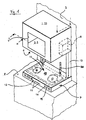
- a high-installation cooking appliance with a housing 1 is shown.
- the back of the housing 1 is mounted on a wall 2 in the manner of a hanging cabinet.
- a cooking chamber 3 is defined, which can be controlled via a front side in the housing 1 introduced viewing window 4.
- the cooking chamber 3 is bounded by a muffle 5, which is provided with a heat-insulating sheath, not shown, and that the muffle 5 has a bottom-side muffle opening 6 .
- the muffle opening 6 is closed with a bottom door 7.
- the bottom door 7 is shown lowered, being with its underside in abutment with a worktop 8 a kitchen equipment.
- the bottom door 7 is in the in the Fig. 2 shown position, the so-called "zero position" to adjust.
- the high-installation cooking appliance has a Drive device 9, 10 on.
- the drive device 9, 10 has a in the Fig. 1 . 2 and 3 shown with dashed lines drive motor 9, which is arranged between the muffle 5 and an outer wall of the housing 1.
- the drive motor 9 is arranged in the region of the rear side of the housing 1 and stands, as in the Fig. 1 or 3 shown in operative connection with a pair of lifting elements 10 which are connected to the bottom door 7. It is according to the schematic side view of the Fig.
- each lifting element 10 is designed as a telescopic linkage, which is attached, for example, on the one hand to the bottom door 7 (for example on a supporting angle protruding from the upper side of the bottom door 7) and on the other hand to a body 33 of the cooking device (for example a cooking appliance mount) the drive motor 9 are operated by means of a control panel 12 and a control circuit 13, which according to the Fig. 1 and 2 front side is arranged on the bottom door 7. As in Fig. 3 shown, the control circuit 13 is located behind the control panel 12 within the bottom door 7.
- the control circuit 13, which is composed here of several spatially and functionally separated and communicating via a communication bus circuit boards, is a central control unit for the device operation is and controls and / or regulates z.
- a heating a method of the bottom door 7, a conversion of user input, a lighting, a pinch protection, a clocking of the radiator 16, 17, 18, 22 and much more.
- a top of the bottom door 7 has a hob 15. Almost the entire surface of the hob 15 is occupied by radiators 16, 17, 18, in Fig. 1 dash-dotted lines are indicated.
- the radiators 16, 17 two spaced apart, different large hotplate radiator, while the radiator 18 is provided between the two cooking area radiators 16,17 surface heating element, which almost encloses the hotplate heaters 16, 17.
- the radiators 16, 17, 18 are configured as radiant heaters, which are covered by a glass ceramic plate 19.
- the glass ceramic plate 19 is further equipped with mounting holes (not shown) through the base for holding support members 20 for Garguta 21 protrude, as well as in Fig. 3 shown.
- FIG. 3 is a schematic and not to scale a Hocheinbau-cooking appliance shown from the front, in which the bottom door 7 is open to rest with the worktop 8. The closed state is shown in dashed lines.
- each traversing panel 25 comprises two push buttons, namely an upper CLOSE button 25a for an upwardly in closing direction traversing bottom door 7 and a.unterere ON push button 25b for a bottom door 7 moving downwards in the opening direction.
- the bottom door 7 moves upwards only if the TO buttons 25a of both travel panels 25 are pressed simultaneously at the same time, if possible; also moves the bottom door 7 only by continuous simultaneous pressing of the UP buttons 25b both traversing panels 25 down, if possible (manual operation).
- manual operation increased user attention is given and also here Both hands are used, a anti-trap then only optional.
- the control circuit 13 comprises a memory unit 27 for storing at least one destination or travel position P0, P1, P2, PZ of the bottom door 7, preferably with volatile memory modules, eg. B. DRAMs. If a target position P0, P1, P2, PZ is stored, the bottom door after operating one of the keys 25a, 25b of the traversing panels 25 as long as in the set direction to move independently until the next target position is reached or one of the Tasten.25a, 25b again is pressed (automatic mode).
- the lowest target position PZ corresponds to the maximum opening
- the (zero) position P0 corresponds to the closed state
- P1 and P2 are freely adjustable intermediate positions.
- a target position P0, P1, P2, PZ may be any position of the bottom door 7 between and including the zero position P0 ("closed position") and the maximum opening position PZ.
- the maximum stored opening position PZ need not be the position with abutment on the work surface 8.
- the drive motor 9 off Fig. 1 has at least one sensor unit 31, 32 on a motor shaft 30, possibly in front of or behind a transmission arranged to measure a travel or a position and / or a speed of the bottom door 7.
- the sensor unit may include one or more induction, reverberation, opto, SAW sensors, and so forth.
- a speed control can realize the speed, for example via a PWM-controlled power semiconductor.
- the distance measurement is automatically re-adjusted by initialization in the zero position P0 of the bottom door 7 at each start, so z.
- a faulty sensor signal output or recording is not traditional.
- Zero-point determination can be determined in several ways.
- the use of switches 24 alone is not optimal due to their comparatively high switching point tolerances.
- two switches 24 are attached to a dash-dot indicated support 34 of the body '33 such that they are actuated when closing the bottom door 7 by the elevating lifting mechanism 10 when the bottom door 7 below a predetermined gap dend between bottom door 7 and muffle opening.
- the switches 24 are located above the muffle 5, for reasons of cooling on the body 33 with a distance from the walls of the muffle 5.
- the switches 24 can also deactivate anti-trap protection when actuated.
- the predetermined gap is here between 12 mm and 4 mm, preferably between 6 mm and 10 mm.
- the switches are here twice for security; it can, for. B. for reasons of cost savings, but, for example, even be present only a switch.
- More reliable is the zero point determination by the use of the measurement of the travel path. If it is typically determined that the travel path is zero, that is, the zero position P0 should be reached, the bottom door 7 is stopped.
- the travel can be determined, for example, by counting the sensor pulses. However, it can lead to a miscalculation of the pulse, which is transmitted without further measures.
- Another method is to determine whether the bottom door still rotates despite activation of the motor 9 or not. However, pinching the floor door, where it stops, can pre-mirror a wrong zero position in the near range.
- the zero-point determination of the floor door 7 is performed by a combination of these methods.
- the control circuit 13 In order for the control circuit 13 to determine the zero position P0 as such and to control the movement of the bottom door 7 during a next opening operation, firstly both switches 24 must be actuated and secondly the travel path must be measured, if appropriate within a specific tolerance range, as belonging to the zero position and / or it may be the engine 9 no longer move when pulling the bottom door, z. B. continue to turn left. In this embodiment, even all three conditions must be met. If this is the case, the control circuit 13 initializes the zero position and sets z. For example, the sensor pulse count returns to zero or another value predetermined for the zero position P0.
- an error message can be output and if necessary the bottom door 7 can be reversed.
- an error message can be output if the sensor pulse count indicates a zero position P0, but the switches 24 have not yet been actuated, or the motor exceeds the tolerance range (eg 1 to 4 sensor pulses, corresponding to, for example, one half to two revolutions of the Motor shaft or gear shaft).
- control circuit 13 is flexible and not limited, so it can be several boards, z. B. include a display board, a control board and an elevator board, which are spatially separated.
Landscapes
- Engineering & Computer Science (AREA)
- Chemical & Material Sciences (AREA)
- Combustion & Propulsion (AREA)
- Mechanical Engineering (AREA)
- General Engineering & Computer Science (AREA)
- Electric Ovens (AREA)
- Power-Operated Mechanisms For Wings (AREA)
- Furnace Housings, Linings, Walls, And Ceilings (AREA)
- Combinations Of Kitchen Furniture (AREA)
- Washing And Drying Of Tableware (AREA)
- Control And Other Processes For Unpacking Of Materials (AREA)
- General Preparation And Processing Of Foods (AREA)
- Vending Machines For Individual Products (AREA)
Claims (13)
- Appareil de cuisson, en particulier appareil de cuisson à haute intégration, comprenant au moins- un moufle (5) délimitant un espace de cuisson (3) avec ouverture de moufle (6),- une porte (7) pour la fermeture de l'ouverture de moufle (6) et- un dispositif d'entraînement (9, 48) commandé par un dispositif de commande (13) pour le déplacement de la porte (7) et- au moins un interrupteur (24), qui, lors de la pose de la porte (7) sur le moufle (5), envoie des signaux d'actionnement pour la détermination d'une position zéro (P0) de la porte (7) au dispositif de commande (13),caractérisé en ce que
le dispositif de commande (13) est aménagé de telle sorte qu'une présence des signaux d'actionnement du au moins un interrupteur (24) est une condition préalable nécessaire mais non suffisante pour la constatation de la position zéro (P0). - Appareil de cuisson selon la revendication 1, caractérisé en ce qu'une position zéro (P0) est constatée lorsque le au moins un interrupteur (24) est actionné et en même temps une mesure d'une course de déplacement de la porte (7) indique que la position zéro (P0) est atteinte au moins à l'intérieur d'une plage de tolérance définie.
- Appareil de cuisson selon la revendication 2, caractérisé en ce que la course de déplacement est déterminée par une mesure d'un nombre de rotations du moteur (9) ou une fraction de celui-ci.
- Appareil de cuisson selon la revendication 3, caractérisé en ce qu'au moins une unité de capteur (31, 32), en particulier une unité de capteur de Hall, est présente pour la mesure d'un nombre de rotations d'un arbre moteur (30) ou d'une fraction de celui-ci et est reliée à l'unité de commande (13).
- Appareil de cuisson selon la revendication 4, caractérisé en ce que l'unité de commande (13) compte les impulsions de capteur transmises par l'unité de capteur (31, 32), en cas de déplacement de la porte (7), à partir d'une position zéro (P0) initiale, et les convertit en une course de déplacement.
- Appareil de cuisson selon l'une quelconque des revendications précédentes, caractérisé en ce qu'une position zéro (P0) est constatée lorsque le au moins un interrupteur (24) est actionné et que simultanément la porte (7) ne peut pas être déplacée davantage lorsque le dispositif d'entraînement (9, 48) est activé.
- Appareil de cuisson selon la revendication 6, caractérisé en ce qu'une immobilisation de la porte (7) est constatée par l'immobilisation du dispositif d'entraînement (9, 48).
- Appareil de cuisson selon l'une quelconque des revendications précédentes, caractérisé en ce que le au moins un interrupteur (34) présente deux interrupteurs (34), qui sont placés en particulier chacun sur un côté de l'appareil de cuisson, une présence des signaux d'actionnement des deux interrupteurs (24) étant une condition préalable nécessaire, mais non suffisante pour la constatation d'une position zéro (P0) de la porte (7).
- Appareil de cuisson selon l'une quelconque des revendications précédentes, caractérisé en ce que le au moins un interrupteur (34) est relié de façon fixe au corps (33) et est actionné par un élément de levage (10), en particulier par un rail télescopique (22, 23).
- Appareil de cuisson selon l'une quelconque des revendications précédentes, caractérisé en ce qu'il s'agit d'un appareil de cuisson à haute intégration et l'ouverture de moufle est une ouverture de moufle (6) côté sol et la porte est une porte de sol (7).
- Procédé pour déterminer une position zéro (P0) d'une porte (7) d'un appareil de cuisson selon l'une quelconque des revendications précédentes, caractérisé en ce que la position zéro (P0) de la porte (7) est constatée dans les cas où simultanément(a) le au moins un interrupteur (24) a été actionné et(b1) a été mesurée, en ce qu'une course de déplacement de la porte (7) correspond à la position zéro (P0) au moins à l'intérieur d'une plage de tolérance et/ou(b2) la porte (7) ne peut pas être déplacée davantage lorsque le dispositif d'entraînement (9, 48) est activé.
- Procédé selon la revendication 11, caractérisé en ce que, après la détermination de la position zéro (P0), celle-ci est définie comme la nouvelle position zéro (P0) précise.
- Procédé selon la revendication 11 ou 12, caractérisé en ce qu'une erreur est constatée au moins dans les cas où
la condition (a) survient et au moins l'une des autres conditions (b1, b2) utilisées pour déterminer la position zéro (P0) ne survient pas,
ou dans les cas où
la condition (a) ne survient pas, mais toutes les autres conditions (b1, b2) utilisées pour la détermination de la position zéro (P0) surviennent.
Applications Claiming Priority (2)
| Application Number | Priority Date | Filing Date | Title |
|---|---|---|---|
| DE102006004375A DE102006004375A1 (de) | 2006-01-31 | 2006-01-31 | Gargerät |
| PCT/EP2007/050763 WO2007088136A1 (fr) | 2006-01-31 | 2007-01-26 | Appareil de cuisson |
Publications (2)
| Publication Number | Publication Date |
|---|---|
| EP1982114A1 EP1982114A1 (fr) | 2008-10-22 |
| EP1982114B1 true EP1982114B1 (fr) | 2009-11-11 |
Family
ID=38197969
Family Applications (1)
| Application Number | Title | Priority Date | Filing Date |
|---|---|---|---|
| EP07704155A Active EP1982114B1 (fr) | 2006-01-31 | 2007-01-26 | Appareil de cuisson |
Country Status (7)
| Country | Link |
|---|---|
| US (1) | US20090139410A1 (fr) |
| EP (1) | EP1982114B1 (fr) |
| AT (1) | ATE448448T1 (fr) |
| DE (2) | DE102006004375A1 (fr) |
| ES (1) | ES2334280T3 (fr) |
| RU (1) | RU2008131782A (fr) |
| WO (1) | WO2007088136A1 (fr) |
Families Citing this family (1)
| Publication number | Priority date | Publication date | Assignee | Title |
|---|---|---|---|---|
| DE102006004380A1 (de) * | 2006-01-31 | 2007-08-02 | BSH Bosch und Siemens Hausgeräte GmbH | Gargerät |
Family Cites Families (24)
| Publication number | Priority date | Publication date | Assignee | Title |
|---|---|---|---|---|
| US1351415A (en) * | 1919-05-28 | 1920-08-31 | John W Coumerilh | Oven-shelf |
| US2003059A (en) * | 1932-04-18 | 1935-05-28 | Teller Stove Designing Corp | Cooking range |
| US2944540A (en) * | 1955-12-22 | 1960-07-12 | Jr Charles C Littell | Oven |
| US2889442A (en) * | 1958-01-10 | 1959-06-02 | Gen Electric | Domestic appliance |
| EP0228007B1 (fr) * | 1985-12-28 | 1992-04-15 | Paul Forkardt GmbH & Co. KG | Machine-outil et son mode d'action |
| US4796599A (en) * | 1988-04-11 | 1989-01-10 | Robert Cooper | Portable cooking grill device |
| JPH0817599B2 (ja) * | 1988-04-18 | 1996-02-21 | 日本オーチス・エレベータ株式会社 | エレベータの速度制御装置 |
| JPH0569275A (ja) * | 1991-09-12 | 1993-03-23 | Fanuc Ltd | 数値制御装置 |
| DE4407919A1 (de) * | 1994-03-09 | 1995-09-14 | Tornado Antriebstech Gmbh | Kompaktsystem zur Steuerung von Getriebeantrieben, insbesondere für Rolltore, Schwenktore, Fördersysteme und dergleichen |
| ATE257212T1 (de) * | 1995-10-28 | 2004-01-15 | Elero Gmbh | Verfahren zum antreiben von elektromotorisch betriebenen markisen oder dergleichen |
| SE507968C2 (sv) * | 1996-07-25 | 1998-08-03 | Electrolux Ab | Bäranordning, t.ex. för väggmonterad hushållsugn |
| US5777280A (en) * | 1996-08-27 | 1998-07-07 | Otis Elevator Company | Calibration routine with adaptive load compensation |
| US5841083A (en) * | 1996-12-18 | 1998-11-24 | Otis Elevator Company | Blocked door detection for an elevator system |
| US6326751B1 (en) * | 1999-08-25 | 2001-12-04 | Wayne-Dalton Corp. | System and related methods for detecting and measuring the operational parameters of a garage door utilizing a lift cable system |
| JP4343381B2 (ja) * | 2000-02-28 | 2009-10-14 | 三菱電機株式会社 | エレベーターの制御装置 |
| US20030030396A1 (en) * | 2000-08-03 | 2003-02-13 | Bastholm Jeppe Christian | Power supply for DC motors |
| DE10059651A1 (de) * | 2000-12-01 | 2002-06-06 | Bsh Bosch Siemens Hausgeraete | Hoch-Einbaugargerät |
| DE10164239A1 (de) * | 2001-12-27 | 2003-07-24 | Bsh Bosch Siemens Hausgeraete | Hocheinbaugagerät |
| DE10164238A1 (de) * | 2001-12-27 | 2003-07-17 | Bsh Bosch Siemens Hausgeraete | Hocheinbaugargerät |
| DE10164236A1 (de) * | 2001-12-27 | 2003-07-17 | Bsh Bosch Siemens Hausgeraete | Hocheinbaugargerät |
| DE10228141A1 (de) * | 2002-06-24 | 2004-01-22 | BSH Bosch und Siemens Hausgeräte GmbH | Gargerät |
| DE10228140A1 (de) * | 2002-06-24 | 2004-01-15 | BSH Bosch und Siemens Hausgeräte GmbH | Gargerät |
| DE102005038916A1 (de) * | 2005-08-17 | 2007-02-22 | BSH Bosch und Siemens Hausgeräte GmbH | Hocheinbau-Gargerät |
| US20090255526A1 (en) * | 2005-08-17 | 2009-10-15 | Bsh Bosch Und Siemens Hausgerate Gmbh | Cooking appliance |
-
2006
- 2006-01-31 DE DE102006004375A patent/DE102006004375A1/de not_active Withdrawn
-
2007
- 2007-01-26 AT AT07704155T patent/ATE448448T1/de active
- 2007-01-26 WO PCT/EP2007/050763 patent/WO2007088136A1/fr active Application Filing
- 2007-01-26 US US12/087,967 patent/US20090139410A1/en not_active Abandoned
- 2007-01-26 DE DE502007001966T patent/DE502007001966D1/de active Active
- 2007-01-26 ES ES07704155T patent/ES2334280T3/es active Active
- 2007-01-26 EP EP07704155A patent/EP1982114B1/fr active Active
- 2007-01-26 RU RU2008131782/03A patent/RU2008131782A/ru not_active Application Discontinuation
Also Published As
| Publication number | Publication date |
|---|---|
| ATE448448T1 (de) | 2009-11-15 |
| EP1982114A1 (fr) | 2008-10-22 |
| WO2007088136A1 (fr) | 2007-08-09 |
| ES2334280T3 (es) | 2010-03-08 |
| DE502007001966D1 (de) | 2009-12-24 |
| RU2008131782A (ru) | 2010-03-10 |
| DE102006004375A1 (de) | 2007-08-02 |
| US20090139410A1 (en) | 2009-06-04 |
Similar Documents
| Publication | Publication Date | Title |
|---|---|---|
| EP1917481B1 (fr) | Appareil de cuisson | |
| EP1931920A1 (fr) | Appareil de cuisson | |
| WO2007020186A1 (fr) | Appareil de cuisson pour installation en hauteur | |
| EP1917480B1 (fr) | Appareil de cuisson | |
| EP1982114B1 (fr) | Appareil de cuisson | |
| EP1982119A2 (fr) | Appareil de cuisson | |
| EP1982121A2 (fr) | Appareil de cuisson | |
| WO2007087941A1 (fr) | Four de cuisson, notamment four de cuisson destiné à être monté en hauteur et procédé de commande du four de cuisson | |
| EP1929212A1 (fr) | Appareil de cuisson | |
| DE102005044690A1 (de) | Hocheinbau-Gargerät | |
| EP1929213A1 (fr) | Appareil de cuisson | |
| WO2007033935A1 (fr) | Appareil de cuisson monte en hauteur | |
| WO2007020162A1 (fr) | Appareil de cuisson | |
| WO2007020166A1 (fr) | Four de cuisson | |
| EP1917478B1 (fr) | Appareil de cuisson | |
| DE102006004376A1 (de) | Pyrolysegerät | |
| WO2007020165A1 (fr) | Appareil de cuisson | |
| EP1767863A2 (fr) | Appareil de cuisson à encastrer en hauteur | |
| WO2007033924A1 (fr) | Appareil de cuisson |
Legal Events
| Date | Code | Title | Description |
|---|---|---|---|
| PUAI | Public reference made under article 153(3) epc to a published international application that has entered the european phase |
Free format text: ORIGINAL CODE: 0009012 |
|
| 17P | Request for examination filed |
Effective date: 20080901 |
|
| AK | Designated contracting states |
Kind code of ref document: A1 Designated state(s): AT BE BG CH CY CZ DE DK EE ES FI FR GB GR HU IE IS IT LI LT LU LV MC NL PL PT RO SE SI SK TR |
|
| 17Q | First examination report despatched |
Effective date: 20090116 |
|
| GRAC | Information related to communication of intention to grant a patent modified |
Free format text: ORIGINAL CODE: EPIDOSCIGR1 |
|
| GRAP | Despatch of communication of intention to grant a patent |
Free format text: ORIGINAL CODE: EPIDOSNIGR1 |
|
| DAX | Request for extension of the european patent (deleted) | ||
| GRAS | Grant fee paid |
Free format text: ORIGINAL CODE: EPIDOSNIGR3 |
|
| GRAA | (expected) grant |
Free format text: ORIGINAL CODE: 0009210 |
|
| AK | Designated contracting states |
Kind code of ref document: B1 Designated state(s): AT BE BG CH CY CZ DE DK EE ES FI FR GB GR HU IE IS IT LI LT LU LV MC NL PL PT RO SE SI SK TR |
|
| REG | Reference to a national code |
Ref country code: GB Ref legal event code: FG4D Free format text: NOT ENGLISH |
|
| REG | Reference to a national code |
Ref country code: CH Ref legal event code: EP |
|
| REG | Reference to a national code |
Ref country code: IE Ref legal event code: FG4D |
|
| REF | Corresponds to: |
Ref document number: 502007001966 Country of ref document: DE Date of ref document: 20091224 Kind code of ref document: P |
|
| REG | Reference to a national code |
Ref country code: ES Ref legal event code: FG2A Ref document number: 2334280 Country of ref document: ES Kind code of ref document: T3 |
|
| NLV1 | Nl: lapsed or annulled due to failure to fulfill the requirements of art. 29p and 29m of the patents act | ||
| LTIE | Lt: invalidation of european patent or patent extension |
Effective date: 20091111 |
|
| PG25 | Lapsed in a contracting state [announced via postgrant information from national office to epo] |
Ref country code: SE Free format text: LAPSE BECAUSE OF FAILURE TO SUBMIT A TRANSLATION OF THE DESCRIPTION OR TO PAY THE FEE WITHIN THE PRESCRIBED TIME-LIMIT Effective date: 20091111 Ref country code: LT Free format text: LAPSE BECAUSE OF FAILURE TO SUBMIT A TRANSLATION OF THE DESCRIPTION OR TO PAY THE FEE WITHIN THE PRESCRIBED TIME-LIMIT Effective date: 20091111 Ref country code: PT Free format text: LAPSE BECAUSE OF FAILURE TO SUBMIT A TRANSLATION OF THE DESCRIPTION OR TO PAY THE FEE WITHIN THE PRESCRIBED TIME-LIMIT Effective date: 20100311 Ref country code: FI Free format text: LAPSE BECAUSE OF FAILURE TO SUBMIT A TRANSLATION OF THE DESCRIPTION OR TO PAY THE FEE WITHIN THE PRESCRIBED TIME-LIMIT Effective date: 20091111 Ref country code: IS Free format text: LAPSE BECAUSE OF FAILURE TO SUBMIT A TRANSLATION OF THE DESCRIPTION OR TO PAY THE FEE WITHIN THE PRESCRIBED TIME-LIMIT Effective date: 20100311 |
|
| PG25 | Lapsed in a contracting state [announced via postgrant information from national office to epo] |
Ref country code: SI Free format text: LAPSE BECAUSE OF FAILURE TO SUBMIT A TRANSLATION OF THE DESCRIPTION OR TO PAY THE FEE WITHIN THE PRESCRIBED TIME-LIMIT Effective date: 20091111 Ref country code: PL Free format text: LAPSE BECAUSE OF FAILURE TO SUBMIT A TRANSLATION OF THE DESCRIPTION OR TO PAY THE FEE WITHIN THE PRESCRIBED TIME-LIMIT Effective date: 20091111 Ref country code: LV Free format text: LAPSE BECAUSE OF FAILURE TO SUBMIT A TRANSLATION OF THE DESCRIPTION OR TO PAY THE FEE WITHIN THE PRESCRIBED TIME-LIMIT Effective date: 20091111 Ref country code: CY Free format text: LAPSE BECAUSE OF FAILURE TO SUBMIT A TRANSLATION OF THE DESCRIPTION OR TO PAY THE FEE WITHIN THE PRESCRIBED TIME-LIMIT Effective date: 20091111 |
|
| REG | Reference to a national code |
Ref country code: IE Ref legal event code: FD4D |
|
| PG25 | Lapsed in a contracting state [announced via postgrant information from national office to epo] |
Ref country code: RO Free format text: LAPSE BECAUSE OF FAILURE TO SUBMIT A TRANSLATION OF THE DESCRIPTION OR TO PAY THE FEE WITHIN THE PRESCRIBED TIME-LIMIT Effective date: 20091111 Ref country code: IE Free format text: LAPSE BECAUSE OF FAILURE TO SUBMIT A TRANSLATION OF THE DESCRIPTION OR TO PAY THE FEE WITHIN THE PRESCRIBED TIME-LIMIT Effective date: 20091111 Ref country code: EE Free format text: LAPSE BECAUSE OF FAILURE TO SUBMIT A TRANSLATION OF THE DESCRIPTION OR TO PAY THE FEE WITHIN THE PRESCRIBED TIME-LIMIT Effective date: 20091111 Ref country code: BG Free format text: LAPSE BECAUSE OF FAILURE TO SUBMIT A TRANSLATION OF THE DESCRIPTION OR TO PAY THE FEE WITHIN THE PRESCRIBED TIME-LIMIT Effective date: 20100211 Ref country code: DK Free format text: LAPSE BECAUSE OF FAILURE TO SUBMIT A TRANSLATION OF THE DESCRIPTION OR TO PAY THE FEE WITHIN THE PRESCRIBED TIME-LIMIT Effective date: 20091111 |
|
| BERE | Be: lapsed |
Owner name: BSH BOSCH UND SIEMENS HAUSGERATE G.M.B.H. Effective date: 20100131 |
|
| PG25 | Lapsed in a contracting state [announced via postgrant information from national office to epo] |
Ref country code: CZ Free format text: LAPSE BECAUSE OF FAILURE TO SUBMIT A TRANSLATION OF THE DESCRIPTION OR TO PAY THE FEE WITHIN THE PRESCRIBED TIME-LIMIT Effective date: 20091111 Ref country code: MC Free format text: LAPSE BECAUSE OF NON-PAYMENT OF DUE FEES Effective date: 20100131 Ref country code: SK Free format text: LAPSE BECAUSE OF FAILURE TO SUBMIT A TRANSLATION OF THE DESCRIPTION OR TO PAY THE FEE WITHIN THE PRESCRIBED TIME-LIMIT Effective date: 20091111 |
|
| PLBE | No opposition filed within time limit |
Free format text: ORIGINAL CODE: 0009261 |
|
| STAA | Information on the status of an ep patent application or granted ep patent |
Free format text: STATUS: NO OPPOSITION FILED WITHIN TIME LIMIT |
|
| 26N | No opposition filed |
Effective date: 20100812 |
|
| PG25 | Lapsed in a contracting state [announced via postgrant information from national office to epo] |
Ref country code: GR Free format text: LAPSE BECAUSE OF FAILURE TO SUBMIT A TRANSLATION OF THE DESCRIPTION OR TO PAY THE FEE WITHIN THE PRESCRIBED TIME-LIMIT Effective date: 20100212 |
|
| PG25 | Lapsed in a contracting state [announced via postgrant information from national office to epo] |
Ref country code: BE Free format text: LAPSE BECAUSE OF NON-PAYMENT OF DUE FEES Effective date: 20100131 |
|
| PGFP | Annual fee paid to national office [announced via postgrant information from national office to epo] |
Ref country code: FR Payment date: 20110201 Year of fee payment: 5 |
|
| PGRI | Patent reinstated in contracting state [announced from national office to epo] |
Ref country code: IT Effective date: 20110501 |
|
| PGFP | Annual fee paid to national office [announced via postgrant information from national office to epo] |
Ref country code: GB Payment date: 20110121 Year of fee payment: 5 |
|
| PGRI | Patent reinstated in contracting state [announced from national office to epo] |
Ref country code: IT Effective date: 20110501 |
|
| REG | Reference to a national code |
Ref country code: CH Ref legal event code: PL |
|
| PG25 | Lapsed in a contracting state [announced via postgrant information from national office to epo] |
Ref country code: CH Free format text: LAPSE BECAUSE OF NON-PAYMENT OF DUE FEES Effective date: 20110131 Ref country code: LI Free format text: LAPSE BECAUSE OF NON-PAYMENT OF DUE FEES Effective date: 20110131 |
|
| GBPC | Gb: european patent ceased through non-payment of renewal fee |
Effective date: 20120126 |
|
| PG25 | Lapsed in a contracting state [announced via postgrant information from national office to epo] |
Ref country code: NL Free format text: LAPSE BECAUSE OF FAILURE TO SUBMIT A TRANSLATION OF THE DESCRIPTION OR TO PAY THE FEE WITHIN THE PRESCRIBED TIME-LIMIT Effective date: 20091111 Ref country code: LU Free format text: LAPSE BECAUSE OF NON-PAYMENT OF DUE FEES Effective date: 20100126 Ref country code: HU Free format text: LAPSE BECAUSE OF FAILURE TO SUBMIT A TRANSLATION OF THE DESCRIPTION OR TO PAY THE FEE WITHIN THE PRESCRIBED TIME-LIMIT Effective date: 20100512 |
|
| REG | Reference to a national code |
Ref country code: FR Ref legal event code: ST Effective date: 20120928 |
|
| PG25 | Lapsed in a contracting state [announced via postgrant information from national office to epo] |
Ref country code: TR Free format text: LAPSE BECAUSE OF FAILURE TO SUBMIT A TRANSLATION OF THE DESCRIPTION OR TO PAY THE FEE WITHIN THE PRESCRIBED TIME-LIMIT Effective date: 20091111 Ref country code: GB Free format text: LAPSE BECAUSE OF NON-PAYMENT OF DUE FEES Effective date: 20120126 |
|
| PG25 | Lapsed in a contracting state [announced via postgrant information from national office to epo] |
Ref country code: FR Free format text: LAPSE BECAUSE OF NON-PAYMENT OF DUE FEES Effective date: 20120131 |
|
| REG | Reference to a national code |
Ref country code: AT Ref legal event code: MM01 Ref document number: 448448 Country of ref document: AT Kind code of ref document: T Effective date: 20120126 |
|
| PG25 | Lapsed in a contracting state [announced via postgrant information from national office to epo] |
Ref country code: AT Free format text: LAPSE BECAUSE OF NON-PAYMENT OF DUE FEES Effective date: 20120126 |
|
| PGFP | Annual fee paid to national office [announced via postgrant information from national office to epo] |
Ref country code: ES Payment date: 20140122 Year of fee payment: 8 Ref country code: IT Payment date: 20140127 Year of fee payment: 8 |
|
| REG | Reference to a national code |
Ref country code: DE Ref legal event code: R081 Ref document number: 502007001966 Country of ref document: DE Owner name: BSH HAUSGERAETE GMBH, DE Free format text: FORMER OWNER: BSH BOSCH UND SIEMENS HAUSGERAETE GMBH, 81739 MUENCHEN, DE Effective date: 20150407 |
|
| PG25 | Lapsed in a contracting state [announced via postgrant information from national office to epo] |
Ref country code: IT Free format text: LAPSE BECAUSE OF NON-PAYMENT OF DUE FEES Effective date: 20150126 |
|
| REG | Reference to a national code |
Ref country code: ES Ref legal event code: FD2A Effective date: 20160226 |
|
| PG25 | Lapsed in a contracting state [announced via postgrant information from national office to epo] |
Ref country code: ES Free format text: LAPSE BECAUSE OF NON-PAYMENT OF DUE FEES Effective date: 20150127 |
|
| REG | Reference to a national code |
Ref country code: DE Ref legal event code: R084 Ref document number: 502007001966 Country of ref document: DE |
|
| PGFP | Annual fee paid to national office [announced via postgrant information from national office to epo] |
Ref country code: DE Payment date: 20240131 Year of fee payment: 18 |