EP1981125B1 - Elektrischer Verbinder mit Schwingungsdämpfungsanordnung - Google Patents
Elektrischer Verbinder mit Schwingungsdämpfungsanordnung Download PDFInfo
- Publication number
- EP1981125B1 EP1981125B1 EP07425209A EP07425209A EP1981125B1 EP 1981125 B1 EP1981125 B1 EP 1981125B1 EP 07425209 A EP07425209 A EP 07425209A EP 07425209 A EP07425209 A EP 07425209A EP 1981125 B1 EP1981125 B1 EP 1981125B1
- Authority
- EP
- European Patent Office
- Prior art keywords
- electric connector
- wall
- side wall
- bottom wall
- damping
- Prior art date
- Legal status (The legal status is an assumption and is not a legal conclusion. Google has not performed a legal analysis and makes no representation as to the accuracy of the status listed.)
- Ceased
Links
- 238000013016 damping Methods 0.000 title claims description 30
- 230000013011 mating Effects 0.000 claims description 7
- 239000004020 conductor Substances 0.000 claims description 6
- 238000003466 welding Methods 0.000 description 2
- 229910000831 Steel Inorganic materials 0.000 description 1
- 238000005452 bending Methods 0.000 description 1
- 239000000463 material Substances 0.000 description 1
- 239000010959 steel Substances 0.000 description 1
Images


Classifications
-
- H—ELECTRICITY
- H01—ELECTRIC ELEMENTS
- H01R—ELECTRICALLY-CONDUCTIVE CONNECTIONS; STRUCTURAL ASSOCIATIONS OF A PLURALITY OF MUTUALLY-INSULATED ELECTRICAL CONNECTING ELEMENTS; COUPLING DEVICES; CURRENT COLLECTORS
- H01R13/00—Details of coupling devices of the kinds covered by groups H01R12/70 or H01R24/00 - H01R33/00
- H01R13/02—Contact members
- H01R13/10—Sockets for co-operation with pins or blades
- H01R13/11—Resilient sockets
- H01R13/113—Resilient sockets co-operating with pins or blades having a rectangular transverse section
Definitions
- the present invention relates to an electric connector in accordance with the preamble of claim 1.
- a prior art electric connector is disclosed, for instance, in EP 1 047 152 .
- This electric connector has an attachment portion for attachment to an electric conductor, a connecting portion for connection to a mating connector and a spring element interposed between such two portions.
- the spring element is incorporated in the connecting portion and at least partly forms one of the surfaces that surround the connecting portion.
- the spring element has an approximately Z-shaped longitudinal section, with one leg of the Z-shaped member incorporated in the attachment portion and the other leg of the Z-shaped member incorporated in the connecting portion.
- the longitudinal Z-shape of the spring element affords vibration damping along the longitudinal axis of the connector and along the vertical axis perpendicular thereto, but is poorly efficient when transverse vibration damping on the electric connector is required.
- Another prior art electric connector is disclosed, for instance, in EP 979 543 .
- This electric connector has an attachment portion for attachment to an electric conductor, a connecting portion for connection to a mating connector and a substantially box-like element interposed between such two portions.
- the box-like element has a bottom wall, connected to the attachment portion, with two opposed side walls extending therefrom. Each side wall is connected to a top wall having a spring contact element extending therefrom.
- This structure provides vibration damping along the vertical axis. Nevertheless, this structure is ineffective in that it is intrinsically rigid when subjected to vibration along the longitudinal direction and along the transverse direction.
- the object of this invention is to provide an electric connector that has such features as to fulfill the above need, while obviating the drawbacks of prior art.
- the electric connector damps any vibration, in the longitudinal, transverse, vertical and torsional directions.
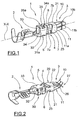
- numeral 1 generally designates an electric connector of the present invention.
- the electric connector extends along a main longitudinal direction X-X and has an attachment portion for attachment to an electric conductor (not shown), a connecting portion 3 for connection to a mating electric connector (not shown), and a damping portion 4 which joins the attachment portion 2 to the connecting portion 3.
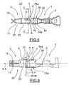
- the damping portion 4 comprises a first wall 5 connected to one of the two portions 2, 3, here to the attachment portion 2, and a second wall 6 connected to the other of the two portions 2, 3, here to the connecting portion 3.
- the first wall 5 and the second wall 6 lie on advantageously parallel planes.
- the first wall 5 is a bottom wall and the second wall 6 is a top wall, such bottom and top walls 5, 6 lying on respective parallel planes.
- the damping portion 4 comprises a single side wall 7 which joins the bottom wall 5 and the top wall 6.
- the bottom wall 5 and the top wall 6 are joined together by one side wall 7.
- the lack of a second retaining member, i.e. a second opposite side wall, for connecting the bottom and top walls provides almost full vibration damping along the vertical axis, as well as transverse and longitudinal vibration damping. Furthermore, this structure of the damping portion was found to be surprisingly effective for torsional and rotational vibration damping, thereby providing reliability and stability to the electric connection between two mating electric connectors.
- the side wall 7 extends in a direction W-W transverse to the bottom and top walls 5, 6, i.e. transverse to the two parallel planes on which such bottom and top walls 5, 6 lie.
- the side wall 7 may extend in a direction W-W perpendicular to the bottom and top walls 5, 6, i.e. perpendicular to the two parallel planes on which such bottom and top walls 5, 6 lie.
- the side wall 7 has a first end 7a connected to the bottom wall 5 and a second end 7b connected to the top wall 6. According to one embodiment of the invention, the direction W-W along which the side wall 7 extends, from the first end 7a to the second end 7b, forms an angle ⁇ with the longitudinal direction X-X of the electric connector 1.
- the angle ⁇ is in a range from 60° to 120°, preferably from 80° to 100°, in the example as shown ( Figures 6 and 8 ) of 95°.
- the direction W-W along which the side wall 7 extends is inclined with respect to the vertical direction Y-Y, perpendicular to the longitudinal direction X-X of the electric connector 1.
- the inclination angle is obviously advantageously in a range from -30° to 30°, preferably from -10° to 10°, in the example as shown ( Figures 6 and 8 ) of 5°.
- the presence of a single side wall for joining the bottom and top walls 5, 6 causes the side wall 7 to be offset from the longitudinal axis X-X of the connector, i.e. the side wall 7 extends between the top wall 6 and the bottom wall 5 along one side of the electric connector 1 only.
- the side wall 7 is offset from the plane P of the longitudinal axis X-X and perpendicular to the parallel planes of the walls 5, 6.
- the side wall 7 lies on a plane parallel to the plane P of the longitudinal axis X-X and perpendicular to the parallel planes of the walls 5, 6.
- the damping portion 4 is asymmetric with respect to the longitudinal axis X-X of the connector 1.
- the damping portion 4 is asymmetric with respect to the plane P of the longitudinal axis X-X and perpendicular to the parallel planes of the walls 5, 6.
- the connecting portion 3 comprises at least two opposite spring contact elements 10, 11, which are connected at a first end 10a, 11a to a substantially box-like element 20 connected to the top wall 6 of the damping portion 4.
- damping portion 4 allows the side wall to exert torsional stresses about its own axis W-W in addition to compressive and bending stresses.
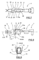
- the substantially box-like element 20 extends along the longitudinal axis X-X and comprises a top wall 21, which is connected to the top wall 6 of the damping portion 4.
- Two opposite parallel side walls 22, 23 extend from the top wall 21 and terminate in two coplanar lower wings 24, 25 parallel to the top wall 21.
- the two lower wings 24, 25 are fixed together, here by a dovetail form fit, to define the box-like element 20.
- the opposite spring contact elements 10, 11, here two contact elements for each side wall 22, 23 extend from the two side walls 22, 23.
- the side wall 21 carries the two contact elements 10 and the opposite side wall 22 carries the two opposite contact elements 11.
- the opposite spring contact elements 10, 11 extend, from the first ends 10a, 11a, in a main longitudinal direction X-X, to free ends 10b, 11b Particularly, the spring contact elements 10, 11 extend from the box-like element 20 and are initially directed toward each other to a point of mutual contact 26 and diverge from such point of contact 26 to form a receiving area 27 for a mating electric connector.
- the electric connector 1 has a second substantially box-like element 30 connected to the bottom wall 5 of the damping portion 4 and interposed between the bottom wall 5 of the damping portion 4 and the attachment portion 2.
- the second substantially box-like element 30 also mainly extends along the longitudinal axis X-X of the connector 1 and comprises a bottom wall 31, which is connected to the bottom wall 5 of the damping portion 4.
- Two opposite parallel side walls 32, 33 extend from the bottom wall 31 and terminate in two coplanar upper wings 34, 35 parallel to the bottom wall 31.
- the two upper wings 34, 35 are not fixed together. Otherwise, fixing arrangements may be provided, i.e. dovetail form fits, spot welding and the like.
- each of the two upper wings 34, 35 has a receptacle 34a, 35a for receiving a locking tab, as described in greater detail hereinbelow.
- Opposite receptacles 31a are formed in the bottom wall 31.
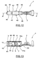
- Figure 10 shows a plan view of the blank that is used for forming the electric connector of Figure 1 , by successive folding steps
- Figure 11 shows a plan view of a second embodiment of the blank to be used for forming the electric connector of Figure 1 , by successive folding operations.
- the blank of Figure 11 is different from the blank of Figure 10 in that the top wall 6 of the damping portion 4 is connected to the upper wing 25 of the substantially box-like element 20 which, according to this embodiment, comprises a bottom wall 21 from which the two opposite parallel opposite side walls 22, 23, which terminate in two coplanar upper wings 24, 25 parallel to the bottom wall 21.
- This embodiment provides material savings in the blanking steps because, as shown by Figure 11 , the bottom wall 5 of the damping portion 4 is aligned with the bottom wall 21 of the box-like element 20.
- the blank of Figure 10 has its bottom wall 5 not aligned with the top wall 21 of the box-like element 20.
- the connector 1 is formed in a manner known per se, through successive folding steps.
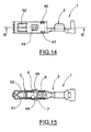
- the damping portion 4 is surrounded by an external spring element 40 for protecting the damping portion 4.
- the external spring element 40 also surrounds the connecting portion 3 to protect the internal spring contact elements 10, 11.
- the external spring element 40 is rigidly fixed to the connecting portion 3 of the electric connector 1 by inwardly folded tabs 46, 47 for engaging the corresponding receptacles 34a, 35a formed in the wings 34, 35 and the receptacles 31a of the bottom wall 31 of the box-like element 30 of the electric connector 1.
- the tabs 46, 47 provide axial locking of the external spring element 40, along the axis X-X, on the electric connector 1.
- the external spring element 40 is a clip, e.g. made of steel, comprising a bottom wall 41, from which two parallel opposite side walls 42, 43 extend and terminate in two coplanar upper wings 44, 45 fixed together, e.g. by welding. As shown by the annexed figures, the tabs 46, 46 are formed in the upper wings 44, 45.
- the clip 40 further comprises two opposite tabs 48, 49 protruding from the two opposite side walls 42, 43 for locking the electric connector 1 in a connector housing.
- the clip 40 further comprises two pairs of opposite spring elements 50, 51 formed in the two opposite side walls 42, 43, whose action is exerted inwardly from the outside onto the internal spring contact elements 10, 11.
- the electric connector of the present invention obviates the above mentioned prior art drawbacks. Namely, the electric connector of the present invention damps any vibration, in the longitudinal, transverse and vertical directions. As a result, the electric connector of the present invention damps vibration exerted along three axes, in the longitudinal, transverse and vertical directions, or multiaxial vibration.
Landscapes
- Connector Housings Or Holding Contact Members (AREA)
- Coupling Device And Connection With Printed Circuit (AREA)
Claims (4)
- Elektrischer Verbinder (1), der sich in einer Hauptlängsrichtung (X-X) erstreckt und umfaßt:- einen Befestigungsabschnitt (2) zur Befestigung an einem elektrischen Leiter,- einen Verbindungsabschnitt (3) zur Verbindung mit einem passenden elektrischen Verbinder,- einen Dämpfungsabschnitt (4), der den Befestigungsabschnitt (2) mit dem Verbindungsabschnitt (3) verbindet und eine untere Wand (5), die mit einem der beiden Abschnitte (2, 3) verbunden ist, und eine obere Wand (6) umfaßt, die mit dem anderen Abschnitt (3) der beiden Abschnitte (2, 3) verbunden ist,
wobei- der Dämpfungsabschnitt (4) eine einzelne Seitenwand (7) umfaßt, die die untere Wand (5) und die obere Wand (6) miteinander verbindet und dadurch den Befestigungsabschnitt (2) und den Verbindungsabschnitt (3) verbindet,- die Seitenwand (7) ein erstes Ende (7a), das mit der unteren Wand (5) verbunden ist, und ein zweites Ende (7b) besitzt, das mit der oberen Wand (6) verbunden ist,- die Seitenwand (7) einen Winkel (α) mit der Längsrichtung (X-X) des elektrischen Verbinders (1) einschließt,- die untere Wand (5) und die obere Wand (6) in entsprechenden parallelen Ebenen liegen,- die Seitenwand (7) sich von dem ersten Ende (7a) zum zweiten Ende (7b) in einer Richtung (W-W) erstreckt, die rechtwinklig zu den parallelen Ebenen der unteren Wand (5) und der oberen Wand (6) verläuft,- die Seitenwand (7) in einer Ebene (P) liegt, die parallel zur Ebene der Längsachse (X-X) und rechtwinklig zu den Ebenen der unteren Wand (5) und der oberen Wand (6) verläuft,
dadurch gekennzeichnet,- daß die Richtung (W-W), entlang welcher sich die Seitenwand (7) erstreckt, bezüglich der vertikalen Richtung (Y-Y), die rechtwinklig zu der longitudinalen Richtung (X-X) verläuft, mit einem Neigungswinkel in einem Bereich bis zu 30 Grad in Richtung auf den Befestigungsabschnitt (2) geneigt ist. - Elektrischer Verbinder (1) nach Anspruch 1, wobei der Verbindungsabschnitt (3) wenigstens zwei gegenüberliegende Federkontaktelemente (10, 11) umfaßt, die an einem ersten Ende (10a, 11a) mit einem im wesentlichen schachtelartigen Element (20) verbunden sind, das mit der entsprechenden Wand (6) des Dämpfungsabschnittes (4) verbunden ist.
- Elektrischer Verbinder (1) nach Anspruch 2, wobei das im wesentlichen schachtelartige Element (20) sich hauptsächlich entlang der Längsache (X-X) des elektrischen Verbinders (1) erstreckt und zwei gegenüberliegende Seitenwände (22, 23) umfaßt, wobei die gegenüberliegenden Federkontaktelemente (10, 11) mit jeder Seitenwand (10, 11) des schachtelartigen Elementes (20) verbunden sind.
- Elektrischer Verbinder (1) nach Anspruch 2 oder 3, wobei sich die wenigstens zwei gegenüberliegenden Federkontaktelemente (10, 11) von den ersten Enden (10a, 11 a) hauptsächlich entlang der Längsachse (X-X) in Richtung auf freie Enden (10b, 11 b) erstrecken.
Priority Applications (3)
| Application Number | Priority Date | Filing Date | Title |
|---|---|---|---|
| EP07425209A EP1981125B1 (de) | 2007-04-12 | 2007-04-12 | Elektrischer Verbinder mit Schwingungsdämpfungsanordnung |
| US12/078,548 US7731550B2 (en) | 2007-04-12 | 2008-04-01 | Electric connector |
| BRPI0801000-5A BRPI0801000B1 (pt) | 2007-04-12 | 2008-04-10 | Conector elétrico |
Applications Claiming Priority (1)
| Application Number | Priority Date | Filing Date | Title |
|---|---|---|---|
| EP07425209A EP1981125B1 (de) | 2007-04-12 | 2007-04-12 | Elektrischer Verbinder mit Schwingungsdämpfungsanordnung |
Publications (2)
| Publication Number | Publication Date |
|---|---|
| EP1981125A1 EP1981125A1 (de) | 2008-10-15 |
| EP1981125B1 true EP1981125B1 (de) | 2011-06-08 |
Family
ID=38372335
Family Applications (1)
| Application Number | Title | Priority Date | Filing Date |
|---|---|---|---|
| EP07425209A Ceased EP1981125B1 (de) | 2007-04-12 | 2007-04-12 | Elektrischer Verbinder mit Schwingungsdämpfungsanordnung |
Country Status (3)
| Country | Link |
|---|---|
| US (1) | US7731550B2 (de) |
| EP (1) | EP1981125B1 (de) |
| BR (1) | BRPI0801000B1 (de) |
Families Citing this family (16)
| Publication number | Priority date | Publication date | Assignee | Title |
|---|---|---|---|---|
| US8123567B2 (en) * | 2007-10-02 | 2012-02-28 | Medtronic, Inc. | Connector assemblies and contacts for implantable medical electrical systems |
| US9403022B2 (en) | 2010-01-29 | 2016-08-02 | Medtronic, Inc. | Header assembly for implantable medical device |
| DE102012017949A1 (de) * | 2011-09-28 | 2013-03-28 | Sumitomo Wiring Systems, Ltd. | Anschlusspassstück |
| US8721376B1 (en) | 2012-11-01 | 2014-05-13 | Avx Corporation | Single element wire to board connector |
| US20140120786A1 (en) | 2012-11-01 | 2014-05-01 | Avx Corporation | Single element wire to board connector |
| DE102014002081B4 (de) | 2013-03-15 | 2024-02-15 | Lear Corporation | Anschluss mit Vorderendenschutz |
| DE102014118688A1 (de) * | 2014-08-21 | 2016-02-25 | Erni Production Gmbh & Co. Kg | Kontaktelement und Steckverbinder |
| DE102014216864B4 (de) * | 2014-08-25 | 2017-05-11 | Robert Bosch Gmbh | Kontaktelement |
| US9647368B2 (en) * | 2014-09-22 | 2017-05-09 | Ideal Industries, Inc. | Terminals for electrical connectors |
| US9391386B2 (en) | 2014-10-06 | 2016-07-12 | Avx Corporation | Caged poke home contact |
| US9450331B1 (en) * | 2015-08-12 | 2016-09-20 | Amphenol East Asia Electronic Technology (Shen Zhen) Co., Ltd. | High current connector |
| TWM534451U (en) * | 2015-12-31 | 2016-12-21 | Alltop Technology Co Ltd | Power connector |
| JP6776098B2 (ja) * | 2016-11-14 | 2020-10-28 | 日本航空電子工業株式会社 | コネクタ端子および電気コネクタ |
| US10320096B2 (en) | 2017-06-01 | 2019-06-11 | Avx Corporation | Flexing poke home contact |
| JP6809517B2 (ja) * | 2018-08-24 | 2021-01-06 | I−Pex株式会社 | 端子及び端子の製造方法 |
| JP6759433B2 (ja) * | 2019-09-04 | 2020-09-23 | イリソ電子工業株式会社 | 端子及びコネクタ |
Family Cites Families (9)
| Publication number | Priority date | Publication date | Assignee | Title |
|---|---|---|---|---|
| DE8713038U1 (de) * | 1987-09-28 | 1987-11-19 | Amp Deutschland Gmbh, 6070 Langen | Buchsenartiger elektrischer Anschluß |
| DE9017536U1 (de) * | 1990-12-28 | 1991-03-21 | Amp Inc., Harrisburg, Pa. | Steckverbindungsbuchse |
| US5551897A (en) * | 1995-02-08 | 1996-09-03 | Osram Sylvania Inc. | Electrical contact |
| US5681190A (en) * | 1995-05-23 | 1997-10-28 | Cardell Corporation | Torsional blade receptacle |
| DE19618928B4 (de) | 1996-05-10 | 2006-04-06 | The Whitaker Corp., Wilmington | Buchsenartiger elektrischer Kontakt und Gehäuse für einen solchen Kontakt |
| JP2001266989A (ja) * | 2000-03-23 | 2001-09-28 | Tyco Electronics Amp Kk | 電気コンタクト |
| US6511336B1 (en) | 2000-05-25 | 2003-01-28 | Illinois Tool Works Inc. | Solderless flex termination for motor tab |
| JP2004158239A (ja) * | 2002-11-05 | 2004-06-03 | Yazaki Corp | 雌端子、及びその雌端子を備えた電気コネクタ |
| US20060292937A1 (en) * | 2005-06-23 | 2006-12-28 | Morello John R | Electrical connector having dual contact function spring contact terminal |
-
2007
- 2007-04-12 EP EP07425209A patent/EP1981125B1/de not_active Ceased
-
2008
- 2008-04-01 US US12/078,548 patent/US7731550B2/en active Active
- 2008-04-10 BR BRPI0801000-5A patent/BRPI0801000B1/pt not_active IP Right Cessation
Also Published As
| Publication number | Publication date |
|---|---|
| BRPI0801000A2 (pt) | 2008-11-25 |
| EP1981125A1 (de) | 2008-10-15 |
| BRPI0801000B1 (pt) | 2019-03-26 |
| US7731550B2 (en) | 2010-06-08 |
| US20080254687A1 (en) | 2008-10-16 |
Similar Documents
| Publication | Publication Date | Title |
|---|---|---|
| EP1981125B1 (de) | Elektrischer Verbinder mit Schwingungsdämpfungsanordnung | |
| EP0677890B1 (de) | Unterstützungsfeder eines elektrischen Verbinders mit anti-Ratter Stützorganen | |
| US9985267B2 (en) | Bus bar attachment to battery terminals | |
| EP2154758B1 (de) | Koaxialverbinder | |
| CN101997238B (zh) | 屏蔽罩、插座连接器以及电子设备 | |
| JP4918424B2 (ja) | シールドボックス | |
| US20100040431A1 (en) | Bolt rotation prevention structure | |
| EP2926415A1 (de) | Stromsteckeranordnung mit einem ausrichtungselement | |
| EP2538106B1 (de) | Zusammengesetzte Wellfeder | |
| US20150050829A1 (en) | Contact element | |
| JP2014530452A (ja) | プラグコネクタ | |
| EP2876733B1 (de) | Elektrische Vorrichtung mit Stromschiene mit flexibler Schweißnahtbördelung | |
| US20150078818A1 (en) | Structure for fixing substrate | |
| US20010051464A1 (en) | Electric connector and terminal | |
| WO2012029660A1 (ja) | コネクタ | |
| JP2015158990A (ja) | フローティング型コネクタ | |
| KR100897014B1 (ko) | 전기 커넥터 | |
| EP3968468B1 (de) | Chiclets für einen chiclet-verbinder | |
| WO2013107865A1 (en) | Adapter contact, adapter, plug contact arrangement and connector/adapter combination for connecting two printed circuit boards | |
| JP5711568B2 (ja) | 突き当て端子 | |
| JP5069181B2 (ja) | プラグインコネクタ | |
| KR102194353B1 (ko) | 커넥터용 메일 터미널 | |
| US20140342602A1 (en) | Splice box | |
| JP2013211249A (ja) | シールド板および当該シールド板が取り付けられたコネクタ | |
| EP3465835B1 (de) | Kontaktelement und kontaktsystem |
Legal Events
| Date | Code | Title | Description |
|---|---|---|---|
| PUAI | Public reference made under article 153(3) epc to a published international application that has entered the european phase |
Free format text: ORIGINAL CODE: 0009012 |
|
| AK | Designated contracting states |
Kind code of ref document: A1 Designated state(s): AT BE BG CH CY CZ DE DK EE ES FI FR GB GR HU IE IS IT LI LT LU LV MC MT NL PL PT RO SE SI SK TR |
|
| AX | Request for extension of the european patent |
Extension state: AL BA HR MK RS |
|
| 17P | Request for examination filed |
Effective date: 20090326 |
|
| 17Q | First examination report despatched |
Effective date: 20090424 |
|
| AKX | Designation fees paid |
Designated state(s): DE FR GB IT |
|
| GRAP | Despatch of communication of intention to grant a patent |
Free format text: ORIGINAL CODE: EPIDOSNIGR1 |
|
| GRAS | Grant fee paid |
Free format text: ORIGINAL CODE: EPIDOSNIGR3 |
|
| GRAA | (expected) grant |
Free format text: ORIGINAL CODE: 0009210 |
|
| AK | Designated contracting states |
Kind code of ref document: B1 Designated state(s): DE FR GB IT |
|
| REG | Reference to a national code |
Ref country code: GB Ref legal event code: FG4D |
|
| REG | Reference to a national code |
Ref country code: DE Ref legal event code: R096 Ref document number: 602007015052 Country of ref document: DE Effective date: 20110721 |
|
| PLBI | Opposition filed |
Free format text: ORIGINAL CODE: 0009260 |
|
| 26 | Opposition filed |
Opponent name: TYCO ELECTRONICS AMP ITALIA S.R.L. Effective date: 20120308 |
|
| PLAX | Notice of opposition and request to file observation + time limit sent |
Free format text: ORIGINAL CODE: EPIDOSNOBS2 |
|
| REG | Reference to a national code |
Ref country code: DE Ref legal event code: R026 Ref document number: 602007015052 Country of ref document: DE Effective date: 20120308 |
|
| PLAF | Information modified related to communication of a notice of opposition and request to file observations + time limit |
Free format text: ORIGINAL CODE: EPIDOSCOBS2 |
|
| PLBB | Reply of patent proprietor to notice(s) of opposition received |
Free format text: ORIGINAL CODE: EPIDOSNOBS3 |
|
| PLCK | Communication despatched that opposition was rejected |
Free format text: ORIGINAL CODE: EPIDOSNREJ1 |
|
| REG | Reference to a national code |
Ref country code: DE Ref legal event code: R100 Ref document number: 602007015052 Country of ref document: DE |
|
| PLBN | Opposition rejected |
Free format text: ORIGINAL CODE: 0009273 |
|
| STAA | Information on the status of an ep patent application or granted ep patent |
Free format text: STATUS: OPPOSITION REJECTED |
|
| 27O | Opposition rejected |
Effective date: 20141212 |
|
| REG | Reference to a national code |
Ref country code: DE Ref legal event code: R100 Ref document number: 602007015052 Country of ref document: DE Effective date: 20141212 |
|
| REG | Reference to a national code |
Ref country code: FR Ref legal event code: PLFP Year of fee payment: 10 |
|
| REG | Reference to a national code |
Ref country code: FR Ref legal event code: PLFP Year of fee payment: 11 |
|
| REG | Reference to a national code |
Ref country code: FR Ref legal event code: PLFP Year of fee payment: 12 |
|
| PGFP | Annual fee paid to national office [announced via postgrant information from national office to epo] |
Ref country code: IT Payment date: 20190423 Year of fee payment: 13 Ref country code: DE Payment date: 20190418 Year of fee payment: 13 |
|
| PGFP | Annual fee paid to national office [announced via postgrant information from national office to epo] |
Ref country code: FR Payment date: 20190424 Year of fee payment: 13 |
|
| PGFP | Annual fee paid to national office [announced via postgrant information from national office to epo] |
Ref country code: GB Payment date: 20190418 Year of fee payment: 13 |
|
| REG | Reference to a national code |
Ref country code: DE Ref legal event code: R119 Ref document number: 602007015052 Country of ref document: DE |
|
| PG25 | Lapsed in a contracting state [announced via postgrant information from national office to epo] |
Ref country code: DE Free format text: LAPSE BECAUSE OF NON-PAYMENT OF DUE FEES Effective date: 20201103 Ref country code: FR Free format text: LAPSE BECAUSE OF NON-PAYMENT OF DUE FEES Effective date: 20200430 |
|
| GBPC | Gb: european patent ceased through non-payment of renewal fee |
Effective date: 20200412 |
|
| PG25 | Lapsed in a contracting state [announced via postgrant information from national office to epo] |
Ref country code: GB Free format text: LAPSE BECAUSE OF NON-PAYMENT OF DUE FEES Effective date: 20200412 |
|
| PG25 | Lapsed in a contracting state [announced via postgrant information from national office to epo] |
Ref country code: IT Free format text: LAPSE BECAUSE OF NON-PAYMENT OF DUE FEES Effective date: 20200412 |