EP1980516A2 - Procédé de mesure et dispositif de détermination de la position de bandes de matériau - Google Patents
Procédé de mesure et dispositif de détermination de la position de bandes de matériau Download PDFInfo
- Publication number
- EP1980516A2 EP1980516A2 EP08153141A EP08153141A EP1980516A2 EP 1980516 A2 EP1980516 A2 EP 1980516A2 EP 08153141 A EP08153141 A EP 08153141A EP 08153141 A EP08153141 A EP 08153141A EP 1980516 A2 EP1980516 A2 EP 1980516A2
- Authority
- EP
- European Patent Office
- Prior art keywords
- webs
- strands
- measuring device
- measuring method
- measuring
- Prior art date
- Legal status (The legal status is an assumption and is not a legal conclusion. Google has not performed a legal analysis and makes no representation as to the accuracy of the status listed.)
- Granted
Links
Images

Classifications
-
- B—PERFORMING OPERATIONS; TRANSPORTING
- B65—CONVEYING; PACKING; STORING; HANDLING THIN OR FILAMENTARY MATERIAL
- B65H—HANDLING THIN OR FILAMENTARY MATERIAL, e.g. SHEETS, WEBS, CABLES
- B65H23/00—Registering, tensioning, smoothing or guiding webs
- B65H23/02—Registering, tensioning, smoothing or guiding webs transversely
- B65H23/0204—Sensing transverse register of web
-
- B—PERFORMING OPERATIONS; TRANSPORTING
- B65—CONVEYING; PACKING; STORING; HANDLING THIN OR FILAMENTARY MATERIAL
- B65H—HANDLING THIN OR FILAMENTARY MATERIAL, e.g. SHEETS, WEBS, CABLES
- B65H2511/00—Dimensions; Position; Numbers; Identification; Occurrences
- B65H2511/10—Size; Dimensions
- B65H2511/12—Width
-
- B—PERFORMING OPERATIONS; TRANSPORTING
- B65—CONVEYING; PACKING; STORING; HANDLING THIN OR FILAMENTARY MATERIAL
- B65H—HANDLING THIN OR FILAMENTARY MATERIAL, e.g. SHEETS, WEBS, CABLES
- B65H2553/00—Sensing or detecting means
- B65H2553/40—Sensing or detecting means using optical, e.g. photographic, elements
- B65H2553/41—Photoelectric detectors
- B65H2553/414—Photoelectric detectors involving receptor receiving light reflected by a reflecting surface and emitted by a separate emitter
-
- B—PERFORMING OPERATIONS; TRANSPORTING
- B65—CONVEYING; PACKING; STORING; HANDLING THIN OR FILAMENTARY MATERIAL
- B65H—HANDLING THIN OR FILAMENTARY MATERIAL, e.g. SHEETS, WEBS, CABLES
- B65H2801/00—Application field
- B65H2801/03—Image reproduction devices
- B65H2801/21—Industrial-size printers, e.g. rotary printing press
Definitions
- the invention relates to a device and a method for determining the position of webs or strands in printing machines.
- the machine is preferably a web-fed rotary printing press, preferably for offset printing, in particular wet offset. It may be a commercial press, or more preferably a large-format newspaper press.
- lateral displacements of a material web can occur before, during and after the convergence of the strands into bundles of strands. Possible reasons for this are paper quality, speed changes, web tension and web stretching, register adjustments, mechanical alignment of the paper guide elements, paper paths, deflections, etc.
- the displacements occur mainly in areas where the strands or bundles are not clamped and guided.
- the individual strands are brought together on the hopper collecting and -einlaufwalze so that they come to lie one above the other.
- the longitudinal section of the material web can only take place on the hopper collecting and infeed roller. In many systems, the longitudinal section takes place before the turning module.
- the strand bundle is not performed.
- the bundles are weakly guided by the forming fold on the funnel.
- the web guide is rotated 90 degrees above the funnel without creating a longitudinal fold. Therefore, individual strands in the strand bundle can shift laterally, especially in the case of tabloid products. Shifts of the strands above the funnels in the bundles of strands are particularly troublesome in tabloid products with so-called false panorama. Strand displacements are possible in principle from the formation of the strands by the longitudinal section of the material web to the finished product.
- the measuring and detection techniques used in known systems can only detect the position of a material web.
- the detection methods are at most capable of detecting more than one material web in one plane.
- the multi-lane is achieved by the sensor is movably mounted and can be moved.
- not more than one track or strand can be detected and measured simultaneously with a prior art measuring device.
- the sensors and their traverse or positioning unit also need space. This space requirement is decisive for the installation location of the sensors.
- the measuring locations are chosen so that the sensors are arranged close to the positioning units and are placed where the accessibility to each material web is guaranteed. An early measurement and detection of the material web position can lead to material web displacements, which can occur later, no longer be detected and therefore can not be corrected automatically.
- a measuring device for detecting a material web is described.
- the sensor is movable parallel to the material web level and is provided after the turning module for each material web guide.
- the layers of the webs are measured individually in front of the hopper before the webs come to rest on each other.
- EP 0 850 763 B1 describes a system for detecting the position and quality of a printed image on a web, which by means of optical means color marks absorbs on the material web. For each side of a material web a sensor is needed.
- an optical or a capacitive measuring system can be used.
- the Messvonichtung can serve to detect web material layers and in particular lateral layers of webs.
- the material webs can be in surface contact with other webs at the measuring location.
- the material webs can also be guided very tightly over one another at the measurement location, so that they can partially touch one another. It is also conceivable that widely spaced webs of material can be detected simultaneously with the same measuring method. In another embodiment, however, the material webs to be detected can also run at least partially in the same planes.
- a single measuring unit can detect the position of at least two strands of material.
- a certain number of strands of material through several measuring units whose number is less than that of the material strands. It is thus possible, for example, for the positions of three material webs to be detected by two measuring units, likewise for detecting 4, 5, 6,..., Web material positives by 3, 4, 5,... N-1 measuring units or even conceivable by even fewer measuring units.
- a measuring unit may further comprise one or more sensors.
- the measuring device can use one-, two- and / or three-dimensional measuring techniques.
- Such measuring techniques are known and used in the geometry testing of objects.
- Known techniques for geometry testing are based on the basic principle of triangulation, such as the light-section method, areal structured illumination and photogrammetry. For example, point, line or area triangulation methods can be used.
- the measuring system can, for example, use the light-section method based on the triangulation principle.
- a fan-shaped laser beam (line projector) is projected onto the measurement object, whereby a sharp light-dark line is generated on the object surface, the course of which can be recorded by a camera and automatically evaluated with special algorithms.
- the triangulation which can be used, for example, in the present invention is an active method and uses a light source, usually a laser, which illuminates the material webs which are to be measured.
- An electronic image converter usually a CCD or CMOS camera or a PSD, registers the scattered light. With knowledge of the beam direction and the distance between camera and light source, the distance from the object to the camera can be determined.
- the connection camera light source and the two beams from and to the object form a triangle, hence the term triangulation.
- the surface relief can be determined with great accuracy, with commercially available sensors up to 0.01 mm.
- the distance information for all points of the pattern can be calculated with a single camera image. In a line, one also speaks of light section, striped patterns are used in the strip projection.
- the advantages resulting from the strand edge detection according to the invention also include the possibility that edges in a strand bundle, ie where several strands come to rest on one another, can be measured. Also, a later measurement than in known systems is possible and therefore a later and sustainable correction and influencing the lateral strand position possible. There are also fewer sensors or measuring systems as required in the prior art to perform the measurements. It is also possible to track relationships and dependencies with regard to web tension and the cutting position.
- laser, LED or LCD grid projectors can serve as light sources for a lighting unit of the measuring device.
- the light used can be projected onto the object to be measured in a punctiform and / or linear manner and / or in the form of a specific pattern.
- the light sources can be operated permanently or pulsating.
- the reflected light can be detected, for example, by CCD, CMOS, PMD sensors or photodiodes.
- One or more sensors and / or one or more light sources may be used per measurement and / or measuring device,
- two-dimensional measuring methods from image processing without triangulation methods such as, for example, image recording with subsequent edge extraction, are also conceivable as measuring methods in the present invention.
- a measuring device can detect a profile of a bundle edge and / or two profiles of a bundle side. In another embodiment, it is possible to detect with a measuring device front and back of a material bundle edge. In a further embodiment, all four strand bundle profiles can be detected with a measuring device. The detection of two strand bundle edges of adjacent bundles is also conceivable.
- the measuring unit can be permanently mounted on a machine element or movably positionable.
- the measuring unit can be used in conjunction with a kinematic motion detection system to locate the exact measuring device position.
- the flat bundles can be bent slightly, in particular to ensure the accurate detection of thin material web layers, of which under certain circumstances only fractions of a millimeter are visible at the bundle edge.
- the bending of the bundles ensures that the individual material web edges are better visible in the bundle.
- the bending of the bundles can for example be done mechanically by baffles or by an air flow.
- the bending of the bundle is conceivable at any point of the material web and can for example already take place above the funnel,
- a simultaneous and synchronized recording of multiple material bundle edges by the measuring device is possible, wherein a speed matched scanning of the material webs for the detection of dynamic processes is advantageous.
- marking in the vicinity of the bundle guide, it is possible to realize an absolute position detection of the individual strand edges in the bundle with respect to a fixed or moved machine element.
- the marking can be two or three-dimensional.
- the marker can also be attached near the strand or bundle center and / or edge.
- a marking is not necessarily required.
- measuring devices in which the detection unit is in a fixed geometric relationship to the illumination unit and also measuring devices in which the detection unit and / or illumination unit are positionable in position or changeable in their position or orientation.
- the paper web thickness can also be determined.
- the paper thickness and / or grammage can be used to improve the measurement, the measurement method can provide information about the position of the individual material webs to each other.
- the front-side spraying or printing the paper rolls with certain patterns is conceivable.
- the outer strand edges can be identified directly and unambiguously by the measuring device, whereby the marking can be invisible to the human eye, for example by using infrared markings, UV markings or the like.
- the markings or marks applied to at least one of the end faces of the paper roll can be detected and / or decoded by machine elements.
- the material webs and in particular the paper rolls can be of different widths due to manufacturing tolerances and can easily change their width during processing (fan in / out). Different strands in their width can lead to other narrower strands or strand edges always remaining covered and hidden for optical measurement.
- means may be provided to determine the width and position of the web before and after the longitudinal cut.
- the roll cell, roll changer, before and after the roll bonding, before or after the printing units, before or after the turning module and any arbitrary point in the course of the printing process or its preparation are conceivable and / or also to the material web on the cutting device and / or align the cutting device on the material web.
- the information obtained can also be used to align the strands with the funnel or to align the funnels with the strands.
- fixed or movable sensors can be provided which detect the paper web edge, the printed image, or certain printed marks.
- the sensors can be moved manually or automatically in at least one coordinate direction. Due to the at least two-fold position detection on the lateral edges of a material web, the width of the material web can be determined,
- the detected print image position can be used to influence the print position laterally as well as in the longitudinal direction of the cut.
- the obtained deviations or measured values via line layers can be used to influence or regulate the strand guide and thus the position of the material web.
- Suitable elements for this purpose are, for example, adjustable eccentric rollers, parallelograms, turner bars, paper roll edges or similar devices.
- the information can be made available to the printing units to set the appropriate print image position.
- the images and / or measured values acquired by the measuring device can be used to visualize the strands or bundles. Conversely, measured values from other detection and measuring devices can be used to influence the measurement or regulation of the material webs.
- Sensors are available, in particular CDD cameras from, for example, Sick, which can simultaneously detect a light section and an image of the object. In this special case, therefore, the edge measurement can take place simultaneously with the image acquisition.
- a visualization of the measured strand edge and bundle is real-time possible. With a normal CCD, this functionality can also be realized, although probably not timely, but sequentially,
- the measuring device additionally determines the lateral position of the printed image per strand.
- images of converging paper webs are recorded with the same measuring device.
- the measuring device is aligned so that the strand edges are measured reliably and the edge of the type area of each strand is visible on a recorded image.
- image data based without marks and branded with or without image data provide absolute reference locations and can be evaluated directly, In the case of a brand-less measurement without image data can eg by Plausibiltuschs phenomenon, Fuzyfiztechnik the decision, multiple detection, etc. and by adaptive and / or knowledge-based systems of the printed image. In this way, it is possible to dispense with upstream systems.
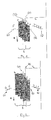
- the two thin vertical lines show the set position X0 (A) of the strands on the one hand and the visual separation (D) of the left edge and right edge of a strand bundle side for the two-sided evaluation of the measurement.
- the result of the measurement (C) is shown schematically as a measuring profile.
- the numbers in the measurement profile correspond to the numbers of the strand edges in the image.
- the measurement profiles on both sides of the figures can be assembled into a profile as would be provided by a single measuring device for one bundle side and two bundle edges.
- a strand (edge 4) is not initially detected by the selected viewing direction on one side.
- the problem can be remedied by further measuring devices on the opposite bundle side and / or by successive and / or recursive correction of the strand layers of the visible strands.
- FIG. 4 is shown schematically the areal registration of the strand edges.
- the angle or slope of the strands (S) relative to other strands (S) or absolutely relative to any coordinate system can be determined.
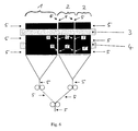
- FIG. 6 various possible positions 5 for the measuring device are shown. These can be arranged both in the area of a collecting roller 3 or an inlet roller 4, or only after a broadsheet 1 or one or more tabloid products 2 have been brought together or brought together.
Applications Claiming Priority (2)
| Application Number | Priority Date | Filing Date | Title |
|---|---|---|---|
| DE102007017885 | 2007-04-13 | ||
| DE102007055087A DE102007055087A1 (de) | 2007-04-13 | 2007-11-16 | Messverfahren und Vorrichtung zur Bestimmung der Lage von Materialbahnen |
Publications (3)
| Publication Number | Publication Date |
|---|---|
| EP1980516A2 true EP1980516A2 (fr) | 2008-10-15 |
| EP1980516A3 EP1980516A3 (fr) | 2009-09-16 |
| EP1980516B1 EP1980516B1 (fr) | 2011-11-02 |
Family
ID=39596526
Family Applications (1)
| Application Number | Title | Priority Date | Filing Date |
|---|---|---|---|
| EP20080153141 Active EP1980516B1 (fr) | 2007-04-13 | 2008-03-20 | Procédé de mesure et dispositif de détermination de la position de bandes de matériau |
Country Status (1)
| Country | Link |
|---|---|
| EP (1) | EP1980516B1 (fr) |
Cited By (2)
| Publication number | Priority date | Publication date | Assignee | Title |
|---|---|---|---|---|
| FR2945619A1 (fr) * | 2009-05-15 | 2010-11-19 | Peugeot Citroen Automobiles Sa | Procede de controle geometrique tridimensionnel d'une caisse de vehicule |
| CN111398288A (zh) * | 2020-03-05 | 2020-07-10 | 包头联方高新技术有限责任公司 | 连铸坯在线热状态下表面全幅周向检测系统、方法及装置 |
Families Citing this family (1)
| Publication number | Priority date | Publication date | Assignee | Title |
|---|---|---|---|---|
| DK3184447T3 (en) * | 2015-12-21 | 2019-04-15 | Tetra Laval Holdings & Finance | PRINTING FOR MORE COATS FOR PRINTING PACKAGING, PACKAGING MACHINE FOR MULTI COATS AND PROCEDURE FOR PRINTING PACKAGING |
Citations (2)
| Publication number | Priority date | Publication date | Assignee | Title |
|---|---|---|---|---|
| EP0850763A1 (fr) | 1996-12-02 | 1998-07-01 | Q.I. Press Controls v.o.f. | Procédé et dispositif de contrÔle de la qualité de l'impression |
| EP1521715B1 (fr) | 2002-07-11 | 2006-02-08 | Koenig & Bauer Aktiengesellschaft | Dispositif pour mesurer un emplacement de bandes de materiaux |
Family Cites Families (3)
| Publication number | Priority date | Publication date | Assignee | Title |
|---|---|---|---|---|
| DE3419524A1 (de) * | 1984-05-25 | 1985-11-28 | Werner H.K. Peters Maschinenfabrik Gmbh, 2000 Hamburg | Vorrichtung zur erfassung und/oder steuerung der kantenlage von papierbahnen in wellpappenmaschinen oder dergleichen |
| DE19802913A1 (de) * | 1998-01-27 | 1999-07-29 | Bhs Corr Masch & Anlagenbau | Vorrichtung zur Erfassung der Kantenlage einer bewegten Materialbahn |
| DE19842585A1 (de) * | 1998-09-17 | 2000-03-23 | Armin Steuer | Speichereinrichtung und ihre Verwendung |
-
2008
- 2008-03-20 EP EP20080153141 patent/EP1980516B1/fr active Active
Patent Citations (2)
| Publication number | Priority date | Publication date | Assignee | Title |
|---|---|---|---|---|
| EP0850763A1 (fr) | 1996-12-02 | 1998-07-01 | Q.I. Press Controls v.o.f. | Procédé et dispositif de contrÔle de la qualité de l'impression |
| EP1521715B1 (fr) | 2002-07-11 | 2006-02-08 | Koenig & Bauer Aktiengesellschaft | Dispositif pour mesurer un emplacement de bandes de materiaux |
Cited By (3)
| Publication number | Priority date | Publication date | Assignee | Title |
|---|---|---|---|---|
| FR2945619A1 (fr) * | 2009-05-15 | 2010-11-19 | Peugeot Citroen Automobiles Sa | Procede de controle geometrique tridimensionnel d'une caisse de vehicule |
| CN111398288A (zh) * | 2020-03-05 | 2020-07-10 | 包头联方高新技术有限责任公司 | 连铸坯在线热状态下表面全幅周向检测系统、方法及装置 |
| CN111398288B (zh) * | 2020-03-05 | 2022-11-15 | 包头联方高新技术有限责任公司 | 连铸坯在线热状态下表面全幅周向检测系统、方法及装置 |
Also Published As
| Publication number | Publication date |
|---|---|
| EP1980516A3 (fr) | 2009-09-16 |
| EP1980516B1 (fr) | 2011-11-02 |
Similar Documents
| Publication | Publication Date | Title |
|---|---|---|
| DE102005018855B4 (de) | Vorrichtung zur Inspektion von Druckererzeugnissen | |
| EP2481585B1 (fr) | Dispositif et procédé de traitement d'une bande de matière d'impression pour produits d'impression | |
| EP0293576B1 (fr) | Procédé d'acquisition des fautes dimensionnelles | |
| EP2520430B1 (fr) | Procédé de détermination d'erreurs de réglage dans une presse à feuilles | |
| DE2921862A1 (de) | Maschine fuer die automatische qualitaetskontrolle an frisch gedruckten banknoten und wertpapieren | |
| DE10149158B4 (de) | Verfahren und Vorrichtung zur Ermittlung der Position einer bedruckten Papierbahn | |
| DE10254836A1 (de) | Verfahren und Vorrichtung zur Regelung des Registers einer Druckmaschine | |
| EP1759844B2 (fr) | Procédé pour corriger l'impression | |
| EP1980516B1 (fr) | Procédé de mesure et dispositif de détermination de la position de bandes de matériau | |
| DE10244437B4 (de) | Verfahren zur Bestimmung der Position und Form von Marken auf einer bedruckten Papierbahn | |
| DE102009023948B4 (de) | Vorrichtung zum Erfassen einer Markierung auf einem flächigen Gegenstand und Verfahren dazu sowie Einrichtung zum Trennen von Abschnitten von einem flächigen Gegenstand | |
| EP3426492B1 (fr) | Procédé de vérification du maintien du registre d'images d'impression à imprimer sur deux faces opposées d'un substrat d'impression | |
| DE102007039372A1 (de) | Schnittregisterregelung in einem Trichteraufbau sowie Verfahren zur Schnittregisterregelung | |
| DE102006030170A1 (de) | Verfahren und Vorrichtung zur Kontrolle der Druckqualität | |
| DE102009047776B4 (de) | Verfahren und Vorrichtung zum Messen einer Laufrichtung einer Substratbahn | |
| DE102007039373B4 (de) | Verfahren zur Überwachung des Stranglaufes in einem Trichteraufbau einer Rotationsdruckmaschine | |
| DE102007006333A1 (de) | Verfahren und Vorrichtung zur Erfassung der Lage und/oder der Form zumindest eines Abschnitts von bewegtem, flachem Bedruckstoff | |
| DE102007055087A1 (de) | Messverfahren und Vorrichtung zur Bestimmung der Lage von Materialbahnen | |
| EP1101601B1 (fr) | Système pour la fabrication de carton ondulé | |
| DE102012018569B3 (de) | Vorrichtung und Verfahren zur Bestimmung von Verzügen bewegter Zuschnittmaterialien | |
| DE102007049192B4 (de) | Vorrichtung und Verfahren zum Transport einer bedruckten Materialbahn | |
| DE102011008359B3 (de) | Verfahren zur Registerregelung mit frei wählbaren Marken | |
| DE2259761A1 (de) | Vorrichtung zum erfassen und aussortieren von makulatur | |
| DE10231323B4 (de) | Vorrichtung zur Messung einer Lage von Materialbahnen | |
| EP3718728B1 (fr) | Système de surveillance de bande et procédé de surveillance de bande |
Legal Events
| Date | Code | Title | Description |
|---|---|---|---|
| PUAI | Public reference made under article 153(3) epc to a published international application that has entered the european phase |
Free format text: ORIGINAL CODE: 0009012 |
|
| AK | Designated contracting states |
Kind code of ref document: A2 Designated state(s): AT BE BG CH CY CZ DE DK EE ES FI FR GB GR HR HU IE IS IT LI LT LU LV MC MT NL NO PL PT RO SE SI SK TR |
|
| AX | Request for extension of the european patent |
Extension state: AL BA MK RS |
|
| PUAL | Search report despatched |
Free format text: ORIGINAL CODE: 0009013 |
|
| AK | Designated contracting states |
Kind code of ref document: A3 Designated state(s): AT BE BG CH CY CZ DE DK EE ES FI FR GB GR HR HU IE IS IT LI LT LU LV MC MT NL NO PL PT RO SE SI SK TR |
|
| AX | Request for extension of the european patent |
Extension state: AL BA MK RS |
|
| RIC1 | Information provided on ipc code assigned before grant |
Ipc: B65H 39/16 20060101ALI20090810BHEP Ipc: B65H 23/02 20060101AFI20080722BHEP |
|
| 17P | Request for examination filed |
Effective date: 20090924 |
|
| 17Q | First examination report despatched |
Effective date: 20091202 |
|
| AKX | Designation fees paid |
Designated state(s): AT BE BG CH CY CZ DE DK EE ES FI FR GB GR HR HU IE IS IT LI LT LU LV MC MT NL NO PL PT RO SE SI SK TR |
|
| GRAP | Despatch of communication of intention to grant a patent |
Free format text: ORIGINAL CODE: EPIDOSNIGR1 |
|
| GRAS | Grant fee paid |
Free format text: ORIGINAL CODE: EPIDOSNIGR3 |
|
| GRAA | (expected) grant |
Free format text: ORIGINAL CODE: 0009210 |
|
| AK | Designated contracting states |
Kind code of ref document: B1 Designated state(s): AT BE BG CH CY CZ DE DK EE ES FI FR GB GR HR HU IE IS IT LI LT LU LV MC MT NL NO PL PT RO SE SI SK TR |
|
| REG | Reference to a national code |
Ref country code: GB Ref legal event code: FG4D Free format text: NOT ENGLISH |
|
| REG | Reference to a national code |
Ref country code: CH Ref legal event code: EP |
|
| REG | Reference to a national code |
Ref country code: IE Ref legal event code: FG4D |
|
| REG | Reference to a national code |
Ref country code: DE Ref legal event code: R096 Ref document number: 502008005449 Country of ref document: DE Effective date: 20120105 |
|
| REG | Reference to a national code |
Ref country code: NL Ref legal event code: VDEP Effective date: 20111102 |
|
| LTIE | Lt: invalidation of european patent or patent extension |
Effective date: 20111102 |
|
| PG25 | Lapsed in a contracting state [announced via postgrant information from national office to epo] |
Ref country code: IS Free format text: LAPSE BECAUSE OF FAILURE TO SUBMIT A TRANSLATION OF THE DESCRIPTION OR TO PAY THE FEE WITHIN THE PRESCRIBED TIME-LIMIT Effective date: 20120302 Ref country code: NO Free format text: LAPSE BECAUSE OF FAILURE TO SUBMIT A TRANSLATION OF THE DESCRIPTION OR TO PAY THE FEE WITHIN THE PRESCRIBED TIME-LIMIT Effective date: 20120202 Ref country code: LT Free format text: LAPSE BECAUSE OF FAILURE TO SUBMIT A TRANSLATION OF THE DESCRIPTION OR TO PAY THE FEE WITHIN THE PRESCRIBED TIME-LIMIT Effective date: 20111102 |
|
| PG25 | Lapsed in a contracting state [announced via postgrant information from national office to epo] |
Ref country code: HR Free format text: LAPSE BECAUSE OF FAILURE TO SUBMIT A TRANSLATION OF THE DESCRIPTION OR TO PAY THE FEE WITHIN THE PRESCRIBED TIME-LIMIT Effective date: 20111102 Ref country code: PL Free format text: LAPSE BECAUSE OF FAILURE TO SUBMIT A TRANSLATION OF THE DESCRIPTION OR TO PAY THE FEE WITHIN THE PRESCRIBED TIME-LIMIT Effective date: 20111102 Ref country code: NL Free format text: LAPSE BECAUSE OF FAILURE TO SUBMIT A TRANSLATION OF THE DESCRIPTION OR TO PAY THE FEE WITHIN THE PRESCRIBED TIME-LIMIT Effective date: 20111102 Ref country code: PT Free format text: LAPSE BECAUSE OF FAILURE TO SUBMIT A TRANSLATION OF THE DESCRIPTION OR TO PAY THE FEE WITHIN THE PRESCRIBED TIME-LIMIT Effective date: 20120302 Ref country code: SE Free format text: LAPSE BECAUSE OF FAILURE TO SUBMIT A TRANSLATION OF THE DESCRIPTION OR TO PAY THE FEE WITHIN THE PRESCRIBED TIME-LIMIT Effective date: 20111102 Ref country code: SI Free format text: LAPSE BECAUSE OF FAILURE TO SUBMIT A TRANSLATION OF THE DESCRIPTION OR TO PAY THE FEE WITHIN THE PRESCRIBED TIME-LIMIT Effective date: 20111102 Ref country code: GR Free format text: LAPSE BECAUSE OF FAILURE TO SUBMIT A TRANSLATION OF THE DESCRIPTION OR TO PAY THE FEE WITHIN THE PRESCRIBED TIME-LIMIT Effective date: 20120203 Ref country code: LV Free format text: LAPSE BECAUSE OF FAILURE TO SUBMIT A TRANSLATION OF THE DESCRIPTION OR TO PAY THE FEE WITHIN THE PRESCRIBED TIME-LIMIT Effective date: 20111102 |
|
| REG | Reference to a national code |
Ref country code: IE Ref legal event code: FD4D |
|
| PG25 | Lapsed in a contracting state [announced via postgrant information from national office to epo] |
Ref country code: CY Free format text: LAPSE BECAUSE OF FAILURE TO SUBMIT A TRANSLATION OF THE DESCRIPTION OR TO PAY THE FEE WITHIN THE PRESCRIBED TIME-LIMIT Effective date: 20111102 |
|
| PG25 | Lapsed in a contracting state [announced via postgrant information from national office to epo] |
Ref country code: BG Free format text: LAPSE BECAUSE OF FAILURE TO SUBMIT A TRANSLATION OF THE DESCRIPTION OR TO PAY THE FEE WITHIN THE PRESCRIBED TIME-LIMIT Effective date: 20120202 Ref country code: SK Free format text: LAPSE BECAUSE OF FAILURE TO SUBMIT A TRANSLATION OF THE DESCRIPTION OR TO PAY THE FEE WITHIN THE PRESCRIBED TIME-LIMIT Effective date: 20111102 Ref country code: DK Free format text: LAPSE BECAUSE OF FAILURE TO SUBMIT A TRANSLATION OF THE DESCRIPTION OR TO PAY THE FEE WITHIN THE PRESCRIBED TIME-LIMIT Effective date: 20111102 Ref country code: CZ Free format text: LAPSE BECAUSE OF FAILURE TO SUBMIT A TRANSLATION OF THE DESCRIPTION OR TO PAY THE FEE WITHIN THE PRESCRIBED TIME-LIMIT Effective date: 20111102 Ref country code: EE Free format text: LAPSE BECAUSE OF FAILURE TO SUBMIT A TRANSLATION OF THE DESCRIPTION OR TO PAY THE FEE WITHIN THE PRESCRIBED TIME-LIMIT Effective date: 20111102 Ref country code: IE Free format text: LAPSE BECAUSE OF FAILURE TO SUBMIT A TRANSLATION OF THE DESCRIPTION OR TO PAY THE FEE WITHIN THE PRESCRIBED TIME-LIMIT Effective date: 20111102 |
|
| PG25 | Lapsed in a contracting state [announced via postgrant information from national office to epo] |
Ref country code: RO Free format text: LAPSE BECAUSE OF FAILURE TO SUBMIT A TRANSLATION OF THE DESCRIPTION OR TO PAY THE FEE WITHIN THE PRESCRIBED TIME-LIMIT Effective date: 20111102 Ref country code: IT Free format text: LAPSE BECAUSE OF FAILURE TO SUBMIT A TRANSLATION OF THE DESCRIPTION OR TO PAY THE FEE WITHIN THE PRESCRIBED TIME-LIMIT Effective date: 20111102 |
|
| PLBE | No opposition filed within time limit |
Free format text: ORIGINAL CODE: 0009261 |
|
| STAA | Information on the status of an ep patent application or granted ep patent |
Free format text: STATUS: NO OPPOSITION FILED WITHIN TIME LIMIT |
|
| BERE | Be: lapsed |
Owner name: WIFAG MASCHINENFABRIK AG Effective date: 20120331 |
|
| 26N | No opposition filed |
Effective date: 20120803 |
|
| PG25 | Lapsed in a contracting state [announced via postgrant information from national office to epo] |
Ref country code: MC Free format text: LAPSE BECAUSE OF NON-PAYMENT OF DUE FEES Effective date: 20120331 |
|
| GBPC | Gb: european patent ceased through non-payment of renewal fee |
Effective date: 20120320 |
|
| REG | Reference to a national code |
Ref country code: DE Ref legal event code: R097 Ref document number: 502008005449 Country of ref document: DE Effective date: 20120803 |
|
| REG | Reference to a national code |
Ref country code: FR Ref legal event code: ST Effective date: 20121130 |
|
| PG25 | Lapsed in a contracting state [announced via postgrant information from national office to epo] |
Ref country code: FR Free format text: LAPSE BECAUSE OF NON-PAYMENT OF DUE FEES Effective date: 20120402 Ref country code: BE Free format text: LAPSE BECAUSE OF NON-PAYMENT OF DUE FEES Effective date: 20120331 Ref country code: GB Free format text: LAPSE BECAUSE OF NON-PAYMENT OF DUE FEES Effective date: 20120320 |
|
| PG25 | Lapsed in a contracting state [announced via postgrant information from national office to epo] |
Ref country code: ES Free format text: LAPSE BECAUSE OF FAILURE TO SUBMIT A TRANSLATION OF THE DESCRIPTION OR TO PAY THE FEE WITHIN THE PRESCRIBED TIME-LIMIT Effective date: 20120213 |
|
| PG25 | Lapsed in a contracting state [announced via postgrant information from national office to epo] |
Ref country code: FI Free format text: LAPSE BECAUSE OF FAILURE TO SUBMIT A TRANSLATION OF THE DESCRIPTION OR TO PAY THE FEE WITHIN THE PRESCRIBED TIME-LIMIT Effective date: 20111102 |
|
| PG25 | Lapsed in a contracting state [announced via postgrant information from national office to epo] |
Ref country code: MT Free format text: LAPSE BECAUSE OF FAILURE TO SUBMIT A TRANSLATION OF THE DESCRIPTION OR TO PAY THE FEE WITHIN THE PRESCRIBED TIME-LIMIT Effective date: 20111102 |
|
| PG25 | Lapsed in a contracting state [announced via postgrant information from national office to epo] |
Ref country code: TR Free format text: LAPSE BECAUSE OF FAILURE TO SUBMIT A TRANSLATION OF THE DESCRIPTION OR TO PAY THE FEE WITHIN THE PRESCRIBED TIME-LIMIT Effective date: 20111102 |
|
| REG | Reference to a national code |
Ref country code: AT Ref legal event code: MM01 Ref document number: 531660 Country of ref document: AT Kind code of ref document: T Effective date: 20130320 |
|
| PG25 | Lapsed in a contracting state [announced via postgrant information from national office to epo] |
Ref country code: LU Free format text: LAPSE BECAUSE OF NON-PAYMENT OF DUE FEES Effective date: 20120320 |
|
| PG25 | Lapsed in a contracting state [announced via postgrant information from national office to epo] |
Ref country code: HU Free format text: LAPSE BECAUSE OF FAILURE TO SUBMIT A TRANSLATION OF THE DESCRIPTION OR TO PAY THE FEE WITHIN THE PRESCRIBED TIME-LIMIT Effective date: 20080320 |
|
| PG25 | Lapsed in a contracting state [announced via postgrant information from national office to epo] |
Ref country code: AT Free format text: LAPSE BECAUSE OF NON-PAYMENT OF DUE FEES Effective date: 20130320 |
|
| PGFP | Annual fee paid to national office [announced via postgrant information from national office to epo] |
Ref country code: DE Payment date: 20160322 Year of fee payment: 9 |
|
| REG | Reference to a national code |
Ref country code: DE Ref legal event code: R119 Ref document number: 502008005449 Country of ref document: DE |
|
| REG | Reference to a national code |
Ref country code: CH Ref legal event code: NV Representative=s name: BOVARD AG PATENT- UND MARKENANWAELTE, CH Ref country code: CH Ref legal event code: PFA Owner name: WIFAG-POLYTYPE HOLDING AG, CH Free format text: FORMER OWNER: WIFAG MASCHINENFABRIK AG, CH |
|
| PG25 | Lapsed in a contracting state [announced via postgrant information from national office to epo] |
Ref country code: DE Free format text: LAPSE BECAUSE OF NON-PAYMENT OF DUE FEES Effective date: 20171003 |
|
| PGFP | Annual fee paid to national office [announced via postgrant information from national office to epo] |
Ref country code: CH Payment date: 20230402 Year of fee payment: 16 |