EP1980471A1 - Schwellerverstärkung für eine Kraftfahrzeugkarosserie - Google Patents
Schwellerverstärkung für eine Kraftfahrzeugkarosserie Download PDFInfo
- Publication number
- EP1980471A1 EP1980471A1 EP20080005076 EP08005076A EP1980471A1 EP 1980471 A1 EP1980471 A1 EP 1980471A1 EP 20080005076 EP20080005076 EP 20080005076 EP 08005076 A EP08005076 A EP 08005076A EP 1980471 A1 EP1980471 A1 EP 1980471A1
- Authority
- EP
- European Patent Office
- Prior art keywords
- sill
- side part
- part according
- reinforcement
- reinforcing plate
- Prior art date
- Legal status (The legal status is an assumption and is not a legal conclusion. Google has not performed a legal analysis and makes no representation as to the accuracy of the status listed.)
- Granted
Links
- 230000002787 reinforcement Effects 0.000 title claims description 33
- 230000003014 reinforcing effect Effects 0.000 claims abstract description 28
- 239000000853 adhesive Substances 0.000 claims abstract description 5
- 230000001070 adhesive effect Effects 0.000 claims abstract description 5
- 238000004519 manufacturing process Methods 0.000 description 4
- 238000005096 rolling process Methods 0.000 description 2
- 239000011324 bead Substances 0.000 description 1
- 238000001125 extrusion Methods 0.000 description 1
- 239000002184 metal Substances 0.000 description 1
- 238000003466 welding Methods 0.000 description 1
Images

Classifications
-
- B—PERFORMING OPERATIONS; TRANSPORTING
- B62—LAND VEHICLES FOR TRAVELLING OTHERWISE THAN ON RAILS
- B62D—MOTOR VEHICLES; TRAILERS
- B62D25/00—Superstructure or monocoque structure sub-units; Parts or details thereof not otherwise provided for
- B62D25/02—Side panels
-
- B—PERFORMING OPERATIONS; TRANSPORTING
- B62—LAND VEHICLES FOR TRAVELLING OTHERWISE THAN ON RAILS
- B62D—MOTOR VEHICLES; TRAILERS
- B62D25/00—Superstructure or monocoque structure sub-units; Parts or details thereof not otherwise provided for
- B62D25/02—Side panels
- B62D25/025—Side sills thereof
-
- B—PERFORMING OPERATIONS; TRANSPORTING
- B62—LAND VEHICLES FOR TRAVELLING OTHERWISE THAN ON RAILS
- B62D—MOTOR VEHICLES; TRAILERS
- B62D25/00—Superstructure or monocoque structure sub-units; Parts or details thereof not otherwise provided for
- B62D25/04—Door pillars ; windshield pillars
-
- B—PERFORMING OPERATIONS; TRANSPORTING
- B62—LAND VEHICLES FOR TRAVELLING OTHERWISE THAN ON RAILS
- B62D—MOTOR VEHICLES; TRAILERS
- B62D27/00—Connections between superstructure or understructure sub-units
- B62D27/02—Connections between superstructure or understructure sub-units rigid
- B62D27/026—Connections by glue bonding
Definitions
- the invention relates to a side part for a motor vehicle body with a longitudinally extending rocker, with a provided on the outer wall outer side plate of the bottom sill and arranged on the provided inner side inner panel and with a arranged between the side plates, a reinforcing plate having sill reinforcement.
- a skirts for such a side part is known in practice.
- the reinforcing plate penetrates a cavity formed by the side panels substantially vertically.
- the invention is based on the problem, a side part of the type mentioned in such a way that it is particularly inexpensive to manufacture and offers the highest possible safety in a crash.
- sill reinforcement is connected in a located between its upper and lower limit central region of the bottom sill with at least one of the side panels and has a vertical, guided to the boundary of the bottom sill section.
- the side part of the invention provides a particularly high level of safety in a crash. Since the floor sills can be assembled from inexpensive sheet metal parts, the side part according to the invention can be manufactured particularly cost-effective.
- the floor sill has a high transverse rigidity, which makes it possible to reduce the sheet thickness of the side panels. The low number of components thanks to the invention also reduces the effort to seal the bottom sill and reduces the weight.
- the sill reinforcement divides a cavity formed by the side plates into at least three chambers.
- a particularly high level of protection of occupants of the motor vehicle can be ensured according to another advantageous embodiment of the invention, when the reinforcing plate is fixed in the central region of the bottom sill on the inner side panel.
- a reliable support of a so-called B-pillar of the motor vehicle body can be easily ensured according to another advantageous development of the invention, when the sill reinforcement is arranged between a rear pillar and a column arranged in the central region of the side part.
- the skirts both in a side impact as well as in a frontal collision on a particularly high stability, when the sill reinforcement is guided by a rear pillar to a front pillar of the side part. Also, this makes the skirts particularly torsionally stiff. This contributes to further increase the safety of the vehicle occupants in a crash.
- the sill reinforcement designed in accordance with another advantageous embodiment of the invention structurally particularly simple when the reinforcing plate of the sill reinforcement at its edges each having a flange for connection to the side plates and between the flanges has a U-shaped deformation with a base and if the base of U-shaped deformation of the sill reinforcement is attached to the at least one of the side plates. Furthermore, the sill reinforcement by the U-shaped deformation on two horizontal legs, resulting in further stiffening of the bottom sill transversely to the longitudinal direction.
- the reinforcing plate has a plurality of U-shaped deformations.
- the U-shaped deformations are formed as cross beads.
- the mounting of the sill reinforcement is particularly simple according to another advantageous embodiment of the invention, when the attachment of the reinforcing plate is formed on the side plate as an adhesive bond.
- other types of connection can be provided for this purpose.
- the side part according to the invention contributes, if the U-shaped deformation of the reinforcing plate of the sill reinforcement is made as a roll profile.
- the reinforcing plate has a constant over the entire length cross-section. Furthermore, this design allows the variable connection of the central column of the side part and also the use of a large number of identical parts in a provided for one or two doors side part.
- connection of the columns to the bottom sill has a particularly high stability, when the sill reinforcement directly with a in at least one of the columns arranged, vertical reinforcing element is connected.
- the side part according to the invention can be composed of particularly rigid frame when several columns are connected to the sill reinforcement and connected to each other via a roof component.
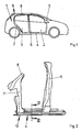
- FIG. 1 shows a motor vehicle with a side wall 1.
- the side wall 1 has a front door 2 and a rear door 3 and extending on the vehicle floor along the direction of travel of the motor vehicle floor sill 4. Furthermore, the side wall 1 a front passenger compartment in the direction of travel limiting Pillar 5, a arranged between the doors 2, 3 middle pillar 6 and the passenger compartment against the direction of travel limiting rear pillar 7.
- the columns 5-7 each extend from the bottom sill 4 to a roof component 8 of a roof 9 of the motor vehicle. About the bottom sill 4 and the roof component 8, the columns 5 - 7 are interconnected.
- FIG. 2 shows enlarged side part 10 of the side wall 1 of the motor vehicle FIG. 1 with the bottom sill 4 and two of the columns 6, 7. It can be seen that the columns 6, 7 are mounted directly on the bottom sill 4.
- FIG. 3 shows greatly enlarged a sectional view taken along the line III - III FIG. 2
- the bottom sill 4 has an inner, the passenger compartment facing side panel 11 and an outer, part of the outer skin of the motor vehicle forming side plate 12. Between the side plates 11, 12, the bottom sill 4 has a sill reinforcement 13 with a reinforcing plate 14.
- Das Reinforcing plate 14 has a U-shaped deformation 15 with two legs 16, 17 and a base 18 in a central, arranged between its upper and lower boundary area.
- the base 18 is fixed to the inner side plate 11 by means of an adhesive connection 19.
- the reinforcing plate 14 of the sill reinforcement 13 has a section 20 guided vertically up to the upper boundary of the base sill 4 and a second section 21 guided vertically up to the lower boundary of the sill 4.
- the reinforcing plate 14 of the sill reinforcement 13 divides one of the side plates 11, 12 of the bottom sill 4 formed Cavity in three chambers 24, 25, 26.
- At the upper and lower limits of the reinforcing plate 14 of the sill reinforcement 13 with flanges 27, 28, 29 of the side plates 11, 12 is welded.
- the reinforcing plate 14 also has flanges 30, 31.
- FIG. 4 shows in a perspective view that the reinforcing plate 14 has a uniform cross section over its entire length. As a result, the reinforcing plate 14 can be manufactured as a roll profile.
Landscapes
- Engineering & Computer Science (AREA)
- Chemical & Material Sciences (AREA)
- Combustion & Propulsion (AREA)
- Transportation (AREA)
- Mechanical Engineering (AREA)
- Body Structure For Vehicles (AREA)
Abstract
Description
- Die Erfindung betrifft ein Seitenteil für eine Kraftfahrzeugkarosserie mit einem sich längs erstreckenden Bodenschweller, mit einem an der vorgesehenen Außenwand angeordneten äußeren Seitenblech des Bodenschwellers und einem an der vorgesehenen Innenseite angeordneten inneren Seitenblech und mit einer zwischen den Seitenblechen angeordneten, ein Verstärkungsblech aufweisenden Schwellerverstärkung.
- Ein Bodenschweller für ein solches Seitenteil ist aus der Praxis bekannt. Bei diesem Bodenschweller durchdringt das Verstärkungsblech einen von den Seitenblechen gebildeten Hohlraum im Wesentlichen vertikal. Um eine ausreichende Sicherheit bei einem Crash herzustellen, ist es jedoch erforderlich, weitere Verstärkungselemente vorzusehen. Dies führt jedoch zu einer sehr hohen Anzahl an Bauteilen des Seitenteils und damit zu hohen Fertigungskosten.
- Aus der
DE 10 2004 033 971 A1 ist zudem ein Bodenschweller bekannt geworden, bei dem ein einziges Seitenblech mit einem im Strangpressen gefertigten zweiten Seitenelement verbunden ist. Das im Strangpressen gefertigte zweite Seitenelement bildet die Schwellerverstärkung. Hierdurch lässt sich der Bodenschweller jedoch nicht aus kostengünstigen Blechen zusammenstellen. - Der Erfindung liegt das Problem zugrunde, ein Seitenteil der eingangs genannten Art so weiterzubilden, dass es besonders kostengünstig zu fertigen ist und eine möglichst hohe Sicherheit bei einem Crash bietet.
- Dieses Problem wird erfindungsgemäß dadurch gelöst, dass die Schwellerverstärkung in einem zwischen seiner oberen und unteren Begrenzung gelegenen mittleren Bereich des Bodenschwellers mit zumindest einem der Seitenbleche verbunden ist und einen vertikalen, bis zur Begrenzung des Bodenschwellers geführten Abschnitt hat.
- Durch diese Gestaltung stützt sich die Schwellerverstärkung bei einer Krafteinleitung in horizontaler Richtung an dem zumindest einem Seitenblech ab. Hierdurch wird eine besonders hohe Quersteifigkeit des Bodenschwellers sichergestellt. Damit bietet das erfindungsgemäße Seitenteil eine besonders hohe Sicherheit bei einem Crash. Da der Bodenschweller aus kostengünstigen Blechteilen zusammengestellt werden kann, lässt sich das erfindungsgemäße Seitenteil besonders kostengünstig fertigen. Durch die Erfindung weist der Bodenschweller eine hohe Quersteifigkeit auf, was eine Reduzierung der Blechdicke der Seitenbleche ermöglicht. Die dank der Erfindung geringe Anzahl an Bauteilen verringert zudem den Aufwand zum Abdichten des Bodenschwellers und verringert das Gewicht.
- Eine besonders hohe Sicherheit bei einem Crash lässt sich gemäß einer vorteilhaften Weiterbildung der Erfindung einfach sicherstellen, wenn die Schwellerverstärkung einen von den Seitenblechen gebildeten Hohlraum in zumindest drei Kammern unterteilt.
- Ein besonders hoher Schutz von Insassen des Kraftfahrzeuges lässt sich gemäß einer anderen vorteilhaften Weiterbildung der Erfindung sicherstellen, wenn das Verstärkungsblech in dem mittleren Bereich des Bodenschwellers an dem inneren Seitenblech befestigt ist.
- Eine zuverlässige Abstützung einer so genannten B-Säule der Kraftfahrzeugkarosserie lässt sich gemäß einer anderen vorteilhaften Weiterbildung der Erfindung einfach sicherstellen, wenn die Schwellerverstärkung zwischen einer hinteren Säule und einer im mittleren Bereich des Seitenteils angeordneten Säule angeordnet ist.
- Der Bodenschweller weist gemäß einer anderen vorteilhaften Weiterbildung der Erfindung sowohl bei einem Seitenaufprall als auch bei einem Frontalaufprall eine besonders hohe Stabilität auf, wenn die Schwellerverstärkung von einer hinteren Säule bis zu einer vorderen Säule des Seitenteils geführt ist. Auch ist hierdurch der Bodenschweller besonders torsionssteif. Dies trägt zur weiteren Erhöhung der Sicherheit der Fahrzeuginsassen bei einem Crash bei.
- Die Schwellerverstärkung gestaltet sich gemäß einer anderen vorteilhaften Weiterbildung der Erfindung konstruktiv besonders einfach, wenn das Verstärkungsblech der Schwellerverstärkung an seinen Rändern jeweils einen Flansch zur Verbindung mit den Seitenblechen hat und zwischen den Flanschen eine U-förmige Verformung mit einer Basis hat und wenn die Basis der U-förmigen Verformung der Schwellerverstärkung an dem zumindest einen der Seitenbleche befestigt ist. Weiterhin weist die Schwellerverstärkung durch die U-förmige Verformung zwei horizontale Schenkel auf, was zur weiteren Versteifung des Bodenschwellers quer zur Längsrichtung führt.
- Zur weiteren Erhöhung der Steifigkeit der Schwellerverstärkung, insbesondere bei quer zur Längsrichtung einwirkenden Kräften, trägt es gemäß einer anderen vorteilhaften Weiterbildung der Erfindung bei, wenn das Verstärkungsblech mehrere U-förmige Verformungen aufweist. Vorzugsweise sind die U-förmigen Verformungen als Quersicken ausgebildet.
- Die Montage der Schwellerverstärkung gestaltet sich gemäß einer anderen vorteilhaften Weiterbildung der Erfindung besonders einfach, wenn die Befestigung des Verstärkungsblechs an dem Seitenblech als Klebeverbindung ausgebildet ist. Alternativ können hierzu auch andere Verbindungsarten vorgesehen sein.
- Zur weiteren Verringerung der Fertigungskosten des erfindungsgemäßen Seitenteils trägt es bei, wenn die U-förmige Verformung des Verstärkungsblechs der Schwellerverstärkung als Rollprofil gefertigt ist.
- Zur weiteren Vereinfachung der Fertigung der Schwellerverstärkung, insbesondere im Walz- oder Rollverfahren trägt es gemäß einer anderen vorteilhaften Weiterbildung der Erfindung bei, wenn das Verstärkungsblech einen über die gesamte Länge konstanten Querschnitt aufweist. Weiterhin ermöglicht diese Gestaltung die variable Anbindung der mittleren Säule des Seitenteils und zudem die Verwendung einer großen Anzahl von Gleichteilen bei einem für eine oder für zwei Türen vorgesehenen Seitenteil.
- Die Anbindung der Säulen an dem Bodenschweller weist gemäß einer anderen vorteilhaften Weiterbildung der Erfindung eine besonders hohe Stabilität auf, wenn die Schwellerverstärkung unmittelbar mit einem in zumindest einer der Säulen angeordneten, vertikalen Verstärkungselement verbunden ist.
- Das erfindungsgemäße Seitenteil lässt sich aus besonders biegesteifen Rahmen zusammenstellen, wenn mehrere Säulen an die Schwellerverstärkung angebunden und über ein Dachbauteil miteinander verbunden sind.
- Die Erfindung lässt verschiedene Ausführungsformen zu. Zur weiteren Verdeutlichung ihres Grundprinzips sind mehrere davon in der Zeichnung dargestellt und werden nachfolgend beschrieben. Die Zeichnung zeigt in
- Fig. 1
- ein Kraftfahrzeug mit einem erfindungsgemäßen Seitenteil in einer Seitenansicht,
- Fig. 2
- einen Teilbereich des Seitenteils aus
Figur 1 vor der Montage, - Fig. 3
- stark vergrößert eine Schnittdarstellung eines Bodenschwellers des Seitenteils aus
Figur 2 in einer Schnittdarstellung entlang der Linie III - III, - Fig. 4
- eine perspektivische Darstellung eines Verstärkungsblechs des Bodenschwellers.
-
Figur 1 zeigt ein Kraftfahrzeug mit einer Seitenwand 1. Die Seitenwand 1 hat eine vordere Tür 2 und eine hintere Tür 3 und einen sich am Fahrzeugboden längs der Fahrtrichtung des Kraftfahrzeuges erstreckenden Bodenschweller 4. Weiterhin weist die Seitenwand 1 eine eine Fahrgastzelle in Fahrtrichtung begrenzende vordere Säule 5, eine zwischen den Türen 2, 3 angeordnete mittlere Säule 6 und eine die Fahrgastzelle gegen die Fahrtrichtung begrenzende hintere Säule 7 auf. Die Säulen 5 - 7 erstrecken sich jeweils von dem Bodenschweller 4 bis zu einem Dachbauteil 8 eines Daches 9 des Kraftfahrzeuges. Über den Bodenschweller 4 und das Dachbauteil 8 sind die Säulen 5 - 7 miteinander verbunden. -
Figur 2 zeigt vergrößert ein Seitenteil 10 der Seitenwand 1 des Kraftfahrzeuges ausFigur 1 mit dem Bodenschweller 4 und zwei der Säulen 6, 7. Hierbei ist zu erkennen, dass die Säulen 6, 7 unmittelbar auf dem Bodenschweller 4 befestigt sind. -
Figur 3 zeigt stark vergrößert eine Schnittdarstellung entlang der Linie III - III ausFigur 2 durch den Bodenschweller 4. Der Bodenschweller 4 hat ein inneres, der Fahrgastzelle zugewandtes Seitenblech 11 und ein äußeres, ein Teil der Außenhaut des Kraftfahrzeuges bildendes Seitenblech 12. Zwischen den Seitenblechen 11, 12 hat der Bodenschweller 4 eine Schwellerverstärkung 13 mit einem Verstärkungsblech 14. Das Verstärkungsblech 14 hat in einem mittleren, zwischen seiner oberen und unteren Begrenzung angeordneten Bereich eine U-förmige Verformung 15 mit zwei Schenkeln 16, 17 und einer Basis 18. Die Basis 18 ist an dem inneren Seitenblech 11 mittels einer Klebeverbindung 19 befestigt. Weiterhin hat das Verstärkungsblech 14 der Schwellerverstärkung 13 einen bis zu der oberen Begrenzung des Bodenschwellers 4 vertikal geführten Abschnitt 20 und einen zweiten, bis zu der unteren Begrenzung des Bodenschwellers 4 vertikal geführten Abschnitt 21. Die zu den Begrenzungen des Bodenschwellers geführten Abschnitte 20, 21 weisen zudem ebenfalls U-förmige Verformungen 22, 23 auf. Damit unterteilt das Verstärkungsblech 14 der Schwellerverstärkung 13 einen von den Seitenblechen 11, 12 des Bodenschwellers 4 gebildeten Hohlraum in drei Kammern 24, 25, 26. An den oberen und unteren Begrenzungen ist das Verstärkungsblech 14 der Schwellerverstärkung 13 mit Flanschen 27, 28, 29 der Seitenbleche 11, 12 verschweißt. Zur Verschweißung mit den Seitenblechen 11, 12 weist das Verstärkungsblech 14 ebenfalls Flansche 30, 31 auf. -
Figur 4 zeigt in einer perspektivischen Darstellung, dass das Verstärkungsblech 14 über seine gesamte Länge einen gleichmäßigen Querschnitt aufweist. Hierdurch kann das Verstärkungsblech 14 als Rollprofil gefertigt werden. -
- 1
- Seitenwand
- 2, 3
- Tür
- 4
- Bodenschweller
- 5 - 7
- Säule
- 8
- Dachbauteil
- 9
- Dach
- 10
- Seitenteil
- 11, 12
- Seitenblech
- 13
- Schwellerverstärkung
- 14
- Verstärkungsblech
- 15
- U-förmige Verformung
- 16, 17
- Schenkel
- 18
- Basis
- 19
- Klebeverbindung
- 20, 21
- Abschnitt
- 22, 23
- U-förmige Verformung
- 24 - 26
- Kammer
- 27 - 29
- Flansch
- 30, 31
- Flansch
Claims (12)
- Seitenteil (10) für eine Kraftfahrzeugkarosserie mit einem sich längs erstreckenden Bodenschweller (4), mit einer an der vorgesehenen Außenwand angeordneten äußeren Seitenblech (12) des Bodenschwellers (4) und einem an der vorgesehenen Innenseite angeordneten inneren Seitenblech (11) und mit einer zwischen den Seitenblechen (11, 12) angeordneten, ein Verstärkungsblech (14) aufweisenden Schwellerverstärkung (13), dadurch gekennzeichnet, dass die Schwellerverstärkung (13) in einem zwischen seiner oberen und unteren Begrenzung gelegenen mittleren Bereich des Bodenschwellers (4) mit zumindest einem der Seitenbleche (11, 12) verbunden ist und einen vertikalen, bis zur Begrenzung des Bodenschwellers (4) geführten Abschnitt (20, 21) hat.
- Seitenteil nach Anspruch 1, dadurch gekennzeichnet, dass die Schwellerverstärkung (13) einen von den Seitenblechen (11, 12) gebildeten Hohlraum in zumindest drei Kammern (24, 25, 26) unterteilt.
- Seitenteil nach Anspruch 1 oder 2, dadurch gekennzeichnet, dass das Verstärkungsblech (14) in dem mittleren Bereich des Bodenschwellers (4) an dem inneren Seitenblech (11) befestigt ist.
- Seitenteil nach zumindest einem der vorhergehenden Ansprüche, dadurch gekennzeichnet, dass die Schwellerverstärkung (13) zwischen einer hinteren Säule (7) und einer im mittleren Bereich des Seitenteils (10) angeordneten Säule (6) angeordnet ist.
- Seitenteil nach zumindest einem der vorhergehenden Ansprüche, dadurch gekennzeichnet, dass die Schwellerverstärkung (13) von einer hinteren Säule (7) bis zu einer vorderen Säule (5) des Seitenteils (10) geführt ist.
- Seitenteil nach zumindest einem der vorhergehenden Ansprüche, dadurch gekennzeichnet, dass das Verstärkungsblech (14) der Schwellerverstärkung (13) an seinen Rändern jeweils einen Flansch (30, 31) zur Verbindung mit den Seitenblechen (11, 12) hat und zwischen den Flanschen (30, 31) eine U-förmige Verformung (15) mit einer Basis (18) hat und dass die Basis (18) der U-förmigen Verformung (15) der Schwellerverstärkung (13) an dem zumindest einen der Seitenbleche (11) befestigt ist.
- Seitenteil nach zumindest einem der vorhergehenden Ansprüche, dadurch gekennzeichnet, dass das Verstärkungsblech (14) mehrere U-förmige Verformungen (15, 22, 23) aufweist.
- Seitenteil nach zumindest einem der vorhergehenden Ansprüche, dadurch gekennzeichnet, dass die Befestigung des Verstärkungsblechs (14) an dem Seitenblech (11) als Klebeverbindung (19) ausgebildet ist.
- Seitenteil nach zumindest einem der vorhergehenden Ansprüche, dadurch gekennzeichnet, dass die U-förmige Verformung (15) des Verstärkungsblechs (14) der Schwellerverstärkung (13) als Rollprofil gefertigt ist.
- Seitenteil nach zumindest einem der vorhergehenden Ansprüche, dadurch gekennzeichnet, dass das Verstärkungsblech (14) einen über die gesamte Länge konstanten Querschnitt aufweist.
- Seitenteil nach zumindest einem der vorhergehenden Ansprüche, dadurch gekennzeichnet, dass die Schwellerverstärkung (13) unmittelbar mit einem in zumindest einer der Säulen (5 - 7) angeordneten vertikalen Verstärkungselement verbunden ist.
- Seitenteil nach zumindest einem der vorhergehenden Ansprüche, dadurch gekennzeichnet, dass mehrere Säulen (5 - 7) an die Schwellerverstärkung (13) angebunden und über ein Dachbauteil (8) miteinander verbunden sind.
Applications Claiming Priority (1)
| Application Number | Priority Date | Filing Date | Title |
|---|---|---|---|
| DE200710017165 DE102007017165A1 (de) | 2007-04-12 | 2007-04-12 | Seitenteil für eine Kraftfahrzeugkarosserie |
Publications (2)
| Publication Number | Publication Date |
|---|---|
| EP1980471A1 true EP1980471A1 (de) | 2008-10-15 |
| EP1980471B1 EP1980471B1 (de) | 2016-02-17 |
Family
ID=39428031
Family Applications (1)
| Application Number | Title | Priority Date | Filing Date |
|---|---|---|---|
| EP08005076.8A Not-in-force EP1980471B1 (de) | 2007-04-12 | 2008-03-19 | Schwellerverstärkung für eine Kraftfahrzeugkarosserie |
Country Status (2)
| Country | Link |
|---|---|
| EP (1) | EP1980471B1 (de) |
| DE (1) | DE102007017165A1 (de) |
Cited By (8)
| Publication number | Priority date | Publication date | Assignee | Title |
|---|---|---|---|---|
| EP2298628A1 (de) * | 2009-09-18 | 2011-03-23 | Audi AG | Fahrzeukarosserieaufbau im Bereich A-Säule unten und Schweller und zugeordnetes Fertigungsverfahren |
| CN105109559A (zh) * | 2015-07-29 | 2015-12-02 | 上汽通用五菱汽车股份有限公司 | 一种门槛加强结构 |
| CN106585725A (zh) * | 2016-12-15 | 2017-04-26 | 重庆飞特车辆技术有限公司 | 一种卡车及其外侧板 |
| CN106627774A (zh) * | 2016-11-25 | 2017-05-10 | 上汽通用五菱汽车股份有限公司 | 一种偏置碰高安全性的a柱结构 |
| US9884650B2 (en) | 2015-02-24 | 2018-02-06 | Volkswagen Aktiengesellschaft | Vehicle body structure |
| CN112441134A (zh) * | 2019-09-04 | 2021-03-05 | 宁波吉利汽车研究开发有限公司 | 一种车辆门槛的安装方法及车辆门槛结构 |
| CN114954687A (zh) * | 2022-05-17 | 2022-08-30 | 阿尔特汽车技术股份有限公司 | 一种门槛总成结构及电动汽车 |
| CN115551770A (zh) * | 2020-05-18 | 2022-12-30 | 安赛乐米塔尔公司 | 用于电动车辆的摇杆加强件 |
Families Citing this family (6)
| Publication number | Priority date | Publication date | Assignee | Title |
|---|---|---|---|---|
| WO2012026028A1 (ja) * | 2010-08-26 | 2012-03-01 | トヨタ自動車株式会社 | 車体のロッカ構造 |
| DE102011103762A1 (de) | 2011-06-08 | 2012-12-13 | GM Global Technology Operations LLC (n. d. Gesetzen des Staates Delaware) | Längsträgeranordnung einer Kraftfahrzeugkarosserie |
| DE102014210089B3 (de) * | 2014-05-27 | 2015-09-24 | Volkswagen Aktiengesellschaft | Bodenstruktur für eine Fahrzeugkarosserie |
| DE102020121094B3 (de) | 2020-08-11 | 2021-10-07 | Bayerische Motoren Werke Aktiengesellschaft | Karosseriestruktur für ein Kraftfahrzeug |
| US12612109B2 (en) * | 2023-08-02 | 2026-04-28 | Mahindra Integrated Solutions Private Limited | Vehicle body side sill reinforcement panel |
| WO2026037556A1 (en) * | 2024-08-13 | 2026-02-19 | Autotech Engineering S.L. | A vehicle arrangement comprising a structure |
Citations (5)
| Publication number | Priority date | Publication date | Assignee | Title |
|---|---|---|---|---|
| US5246264A (en) | 1991-08-02 | 1993-09-21 | Mazda Motor Corporation | Side body structure of automotive vehicle |
| JPH05319301A (ja) | 1992-05-18 | 1993-12-03 | Suzuki Motor Corp | 自動車の車体構造 |
| JPH1159489A (ja) * | 1997-08-19 | 1999-03-02 | Mazda Motor Corp | 車両の車体構造 |
| DE10118202A1 (de) | 2000-08-17 | 2002-03-07 | Hyundai Motor Co Ltd | Paneelstruktur einer Fahrzeugkarosserie |
| DE102004033971A1 (de) | 2004-07-14 | 2006-02-02 | Audi Ag | Karosseriebauteil in Form von aus Metallblechen bestehenden Längs- und/oder Querträger insbesondere in Form eines Schwellers |
Family Cites Families (3)
| Publication number | Priority date | Publication date | Assignee | Title |
|---|---|---|---|---|
| DE19528874C2 (de) * | 1995-08-05 | 1998-02-26 | Volkswagen Ag | Tragstruktur für ein Fahrzeug |
| DE10003878B4 (de) * | 2000-01-28 | 2004-05-13 | Linde + Pullman Ag | Zusatzelement |
| JP2003291858A (ja) * | 2002-04-02 | 2003-10-15 | Honda Motor Co Ltd | 車両のサイドシル補強構造 |
-
2007
- 2007-04-12 DE DE200710017165 patent/DE102007017165A1/de not_active Ceased
-
2008
- 2008-03-19 EP EP08005076.8A patent/EP1980471B1/de not_active Not-in-force
Patent Citations (5)
| Publication number | Priority date | Publication date | Assignee | Title |
|---|---|---|---|---|
| US5246264A (en) | 1991-08-02 | 1993-09-21 | Mazda Motor Corporation | Side body structure of automotive vehicle |
| JPH05319301A (ja) | 1992-05-18 | 1993-12-03 | Suzuki Motor Corp | 自動車の車体構造 |
| JPH1159489A (ja) * | 1997-08-19 | 1999-03-02 | Mazda Motor Corp | 車両の車体構造 |
| DE10118202A1 (de) | 2000-08-17 | 2002-03-07 | Hyundai Motor Co Ltd | Paneelstruktur einer Fahrzeugkarosserie |
| DE102004033971A1 (de) | 2004-07-14 | 2006-02-02 | Audi Ag | Karosseriebauteil in Form von aus Metallblechen bestehenden Längs- und/oder Querträger insbesondere in Form eines Schwellers |
Cited By (10)
| Publication number | Priority date | Publication date | Assignee | Title |
|---|---|---|---|---|
| EP2298628A1 (de) * | 2009-09-18 | 2011-03-23 | Audi AG | Fahrzeukarosserieaufbau im Bereich A-Säule unten und Schweller und zugeordnetes Fertigungsverfahren |
| US9884650B2 (en) | 2015-02-24 | 2018-02-06 | Volkswagen Aktiengesellschaft | Vehicle body structure |
| CN105109559A (zh) * | 2015-07-29 | 2015-12-02 | 上汽通用五菱汽车股份有限公司 | 一种门槛加强结构 |
| CN106627774A (zh) * | 2016-11-25 | 2017-05-10 | 上汽通用五菱汽车股份有限公司 | 一种偏置碰高安全性的a柱结构 |
| CN106627774B (zh) * | 2016-11-25 | 2023-08-08 | 上汽通用五菱汽车股份有限公司 | 一种偏置碰高安全性的a柱结构 |
| CN106585725A (zh) * | 2016-12-15 | 2017-04-26 | 重庆飞特车辆技术有限公司 | 一种卡车及其外侧板 |
| CN106585725B (zh) * | 2016-12-15 | 2019-09-10 | 重庆飞特车辆技术有限公司 | 一种卡车及其外侧板 |
| CN112441134A (zh) * | 2019-09-04 | 2021-03-05 | 宁波吉利汽车研究开发有限公司 | 一种车辆门槛的安装方法及车辆门槛结构 |
| CN115551770A (zh) * | 2020-05-18 | 2022-12-30 | 安赛乐米塔尔公司 | 用于电动车辆的摇杆加强件 |
| CN114954687A (zh) * | 2022-05-17 | 2022-08-30 | 阿尔特汽车技术股份有限公司 | 一种门槛总成结构及电动汽车 |
Also Published As
| Publication number | Publication date |
|---|---|
| DE102007017165A1 (de) | 2008-10-16 |
| EP1980471B1 (de) | 2016-02-17 |
Similar Documents
| Publication | Publication Date | Title |
|---|---|---|
| EP1980471B1 (de) | Schwellerverstärkung für eine Kraftfahrzeugkarosserie | |
| EP2014539B1 (de) | Kraftfahrzeugkarosserie mit seitlichen Schwellern | |
| DE102012209484A1 (de) | Fahrzeugsäulenanordnung | |
| DE102014004183B4 (de) | Karosserielängsträger sowie Verfahren zur Herstellung eines Karosserielängsträgers mittels eines Mehrkammerhohlprofils | |
| DE202014103276U1 (de) | Kurze Versatz-Blechverstärkung zur Begrenzung der Rotation während eines Unfalls | |
| DE102012205882A1 (de) | Fahrzeugdachstützenanordnung | |
| DE4104894C2 (de) | Fahrzeugkarosserie | |
| DE102013001945B4 (de) | Schweller für eine Fahrzeugkarosserie | |
| DE102008021224B4 (de) | Schienenfahrzeug | |
| WO2006079482A1 (de) | Karosserie-bauteil eines kraftfahrzeuges | |
| DE10032663B4 (de) | Kraftwagen mit einer selbsttragenden Karosserie | |
| DE102005011834B4 (de) | Seitlicher Dachrahmen für ein Kraftfahrzeug | |
| WO2022002504A1 (de) | Verfahren zum fertigen einer karosserie für einen kraftwagen und karosserie für einen kraftwagen | |
| EP1632422B1 (de) | Karosserie für ein Kraftfahrzeug | |
| DE102006014983A1 (de) | Querträgerstruktur für einen Sitzbereich eines Fahrzeugs | |
| DE102006040032A1 (de) | Fahrzeug mit einer gegen einen Seitenaufprall ausgelegten Instrumententafel | |
| DE10260795B4 (de) | Karosseriesäule eines Personenkraftwagens | |
| DE102004016188B4 (de) | Hilfsrahmen an einem Kraftfahrzeug | |
| EP1449746B1 (de) | Kraftfahrzeugkarosserie mit Verstärkungsblech zwischen Dachspriegel, Säule und Seitenwand | |
| EP1717130A1 (de) | Instrumententafelträgerstruktur | |
| DE102016112344A1 (de) | Verstärkungsvorrichtung für eine Kraftfahrzeugtür | |
| DE102008027199B4 (de) | Queraussteifungsstruktur für ein Kraftfahrzeug | |
| WO2022122475A2 (de) | Speichergehäuse für einen energiespeicher eines kraftwagens | |
| DE102004045867B4 (de) | Bodenquerträger | |
| DE102024135422B3 (de) | Instrumententafelträger |
Legal Events
| Date | Code | Title | Description |
|---|---|---|---|
| PUAI | Public reference made under article 153(3) epc to a published international application that has entered the european phase |
Free format text: ORIGINAL CODE: 0009012 |
|
| AK | Designated contracting states |
Kind code of ref document: A1 Designated state(s): AT BE BG CH CY CZ DE DK EE ES FI FR GB GR HR HU IE IS IT LI LT LU LV MC MT NL NO PL PT RO SE SI SK TR |
|
| AX | Request for extension of the european patent |
Extension state: AL BA MK RS |
|
| 17P | Request for examination filed |
Effective date: 20090415 |
|
| 17Q | First examination report despatched |
Effective date: 20090514 |
|
| AKX | Designation fees paid |
Designated state(s): AT BE BG CH CY CZ DE DK EE ES FI FR GB GR HR HU IE IS IT LI LT LU LV MC MT NL NO PL PT RO SE SI SK TR |
|
| RAP1 | Party data changed (applicant data changed or rights of an application transferred) |
Owner name: GM GLOBAL TECHNOLOGY OPERATIONS LLC |
|
| GRAP | Despatch of communication of intention to grant a patent |
Free format text: ORIGINAL CODE: EPIDOSNIGR1 |
|
| INTG | Intention to grant announced |
Effective date: 20151021 |
|
| GRAS | Grant fee paid |
Free format text: ORIGINAL CODE: EPIDOSNIGR3 |
|
| GRAA | (expected) grant |
Free format text: ORIGINAL CODE: 0009210 |
|
| AK | Designated contracting states |
Kind code of ref document: B1 Designated state(s): AT BE BG CH CY CZ DE DK EE ES FI FR GB GR HR HU IE IS IT LI LT LU LV MC MT NL NO PL PT RO SE SI SK TR |
|
| REG | Reference to a national code |
Ref country code: GB Ref legal event code: FG4D Free format text: NOT ENGLISH |
|
| REG | Reference to a national code |
Ref country code: CH Ref legal event code: EP |
|
| REG | Reference to a national code |
Ref country code: IE Ref legal event code: FG4D Free format text: LANGUAGE OF EP DOCUMENT: GERMAN Ref country code: FR Ref legal event code: PLFP Year of fee payment: 9 |
|
| REG | Reference to a national code |
Ref country code: AT Ref legal event code: REF Ref document number: 775502 Country of ref document: AT Kind code of ref document: T Effective date: 20160315 |
|
| REG | Reference to a national code |
Ref country code: DE Ref legal event code: R096 Ref document number: 502008013828 Country of ref document: DE |
|
| REG | Reference to a national code |
Ref country code: NL Ref legal event code: MP Effective date: 20160217 |
|
| REG | Reference to a national code |
Ref country code: LT Ref legal event code: MG4D |
|
| PG25 | Lapsed in a contracting state [announced via postgrant information from national office to epo] |
Ref country code: ES Free format text: LAPSE BECAUSE OF FAILURE TO SUBMIT A TRANSLATION OF THE DESCRIPTION OR TO PAY THE FEE WITHIN THE PRESCRIBED TIME-LIMIT Effective date: 20160217 Ref country code: GR Free format text: LAPSE BECAUSE OF FAILURE TO SUBMIT A TRANSLATION OF THE DESCRIPTION OR TO PAY THE FEE WITHIN THE PRESCRIBED TIME-LIMIT Effective date: 20160518 Ref country code: IT Free format text: LAPSE BECAUSE OF FAILURE TO SUBMIT A TRANSLATION OF THE DESCRIPTION OR TO PAY THE FEE WITHIN THE PRESCRIBED TIME-LIMIT Effective date: 20160217 Ref country code: NO Free format text: LAPSE BECAUSE OF FAILURE TO SUBMIT A TRANSLATION OF THE DESCRIPTION OR TO PAY THE FEE WITHIN THE PRESCRIBED TIME-LIMIT Effective date: 20160517 Ref country code: FI Free format text: LAPSE BECAUSE OF FAILURE TO SUBMIT A TRANSLATION OF THE DESCRIPTION OR TO PAY THE FEE WITHIN THE PRESCRIBED TIME-LIMIT Effective date: 20160217 |
|
| PG25 | Lapsed in a contracting state [announced via postgrant information from national office to epo] |
Ref country code: LT Free format text: LAPSE BECAUSE OF FAILURE TO SUBMIT A TRANSLATION OF THE DESCRIPTION OR TO PAY THE FEE WITHIN THE PRESCRIBED TIME-LIMIT Effective date: 20160217 Ref country code: SE Free format text: LAPSE BECAUSE OF FAILURE TO SUBMIT A TRANSLATION OF THE DESCRIPTION OR TO PAY THE FEE WITHIN THE PRESCRIBED TIME-LIMIT Effective date: 20160217 Ref country code: BE Free format text: LAPSE BECAUSE OF NON-PAYMENT OF DUE FEES Effective date: 20160331 Ref country code: PT Free format text: LAPSE BECAUSE OF FAILURE TO SUBMIT A TRANSLATION OF THE DESCRIPTION OR TO PAY THE FEE WITHIN THE PRESCRIBED TIME-LIMIT Effective date: 20160617 Ref country code: LV Free format text: LAPSE BECAUSE OF FAILURE TO SUBMIT A TRANSLATION OF THE DESCRIPTION OR TO PAY THE FEE WITHIN THE PRESCRIBED TIME-LIMIT Effective date: 20160217 Ref country code: PL Free format text: LAPSE BECAUSE OF FAILURE TO SUBMIT A TRANSLATION OF THE DESCRIPTION OR TO PAY THE FEE WITHIN THE PRESCRIBED TIME-LIMIT Effective date: 20160217 Ref country code: NL Free format text: LAPSE BECAUSE OF FAILURE TO SUBMIT A TRANSLATION OF THE DESCRIPTION OR TO PAY THE FEE WITHIN THE PRESCRIBED TIME-LIMIT Effective date: 20160217 |
|
| PG25 | Lapsed in a contracting state [announced via postgrant information from national office to epo] |
Ref country code: EE Free format text: LAPSE BECAUSE OF FAILURE TO SUBMIT A TRANSLATION OF THE DESCRIPTION OR TO PAY THE FEE WITHIN THE PRESCRIBED TIME-LIMIT Effective date: 20160217 Ref country code: DK Free format text: LAPSE BECAUSE OF FAILURE TO SUBMIT A TRANSLATION OF THE DESCRIPTION OR TO PAY THE FEE WITHIN THE PRESCRIBED TIME-LIMIT Effective date: 20160217 |
|
| REG | Reference to a national code |
Ref country code: CH Ref legal event code: PL |
|
| REG | Reference to a national code |
Ref country code: DE Ref legal event code: R097 Ref document number: 502008013828 Country of ref document: DE |
|
| PG25 | Lapsed in a contracting state [announced via postgrant information from national office to epo] |
Ref country code: RO Free format text: LAPSE BECAUSE OF FAILURE TO SUBMIT A TRANSLATION OF THE DESCRIPTION OR TO PAY THE FEE WITHIN THE PRESCRIBED TIME-LIMIT Effective date: 20160217 Ref country code: SK Free format text: LAPSE BECAUSE OF FAILURE TO SUBMIT A TRANSLATION OF THE DESCRIPTION OR TO PAY THE FEE WITHIN THE PRESCRIBED TIME-LIMIT Effective date: 20160217 Ref country code: CZ Free format text: LAPSE BECAUSE OF FAILURE TO SUBMIT A TRANSLATION OF THE DESCRIPTION OR TO PAY THE FEE WITHIN THE PRESCRIBED TIME-LIMIT Effective date: 20160217 |
|
| PLBE | No opposition filed within time limit |
Free format text: ORIGINAL CODE: 0009261 |
|
| STAA | Information on the status of an ep patent application or granted ep patent |
Free format text: STATUS: NO OPPOSITION FILED WITHIN TIME LIMIT |
|
| REG | Reference to a national code |
Ref country code: IE Ref legal event code: MM4A |
|
| 26N | No opposition filed |
Effective date: 20161118 |
|
| PG25 | Lapsed in a contracting state [announced via postgrant information from national office to epo] |
Ref country code: CH Free format text: LAPSE BECAUSE OF NON-PAYMENT OF DUE FEES Effective date: 20160331 Ref country code: LI Free format text: LAPSE BECAUSE OF NON-PAYMENT OF DUE FEES Effective date: 20160331 Ref country code: IE Free format text: LAPSE BECAUSE OF NON-PAYMENT OF DUE FEES Effective date: 20160319 |
|
| REG | Reference to a national code |
Ref country code: FR Ref legal event code: PLFP Year of fee payment: 10 |
|
| PG25 | Lapsed in a contracting state [announced via postgrant information from national office to epo] |
Ref country code: SI Free format text: LAPSE BECAUSE OF FAILURE TO SUBMIT A TRANSLATION OF THE DESCRIPTION OR TO PAY THE FEE WITHIN THE PRESCRIBED TIME-LIMIT Effective date: 20160217 Ref country code: BG Free format text: LAPSE BECAUSE OF FAILURE TO SUBMIT A TRANSLATION OF THE DESCRIPTION OR TO PAY THE FEE WITHIN THE PRESCRIBED TIME-LIMIT Effective date: 20160517 |
|
| PGFP | Annual fee paid to national office [announced via postgrant information from national office to epo] |
Ref country code: FR Payment date: 20170213 Year of fee payment: 10 |
|
| REG | Reference to a national code |
Ref country code: AT Ref legal event code: MM01 Ref document number: 775502 Country of ref document: AT Kind code of ref document: T Effective date: 20160319 |
|
| PGFP | Annual fee paid to national office [announced via postgrant information from national office to epo] |
Ref country code: GB Payment date: 20170315 Year of fee payment: 10 |
|
| PG25 | Lapsed in a contracting state [announced via postgrant information from national office to epo] |
Ref country code: MT Free format text: LAPSE BECAUSE OF FAILURE TO SUBMIT A TRANSLATION OF THE DESCRIPTION OR TO PAY THE FEE WITHIN THE PRESCRIBED TIME-LIMIT Effective date: 20160217 Ref country code: AT Free format text: LAPSE BECAUSE OF NON-PAYMENT OF DUE FEES Effective date: 20160319 |
|
| PGFP | Annual fee paid to national office [announced via postgrant information from national office to epo] |
Ref country code: DE Payment date: 20180306 Year of fee payment: 11 |
|
| PG25 | Lapsed in a contracting state [announced via postgrant information from national office to epo] |
Ref country code: HU Free format text: LAPSE BECAUSE OF FAILURE TO SUBMIT A TRANSLATION OF THE DESCRIPTION OR TO PAY THE FEE WITHIN THE PRESCRIBED TIME-LIMIT; INVALID AB INITIO Effective date: 20080319 Ref country code: CY Free format text: LAPSE BECAUSE OF FAILURE TO SUBMIT A TRANSLATION OF THE DESCRIPTION OR TO PAY THE FEE WITHIN THE PRESCRIBED TIME-LIMIT Effective date: 20160217 |
|
| PG25 | Lapsed in a contracting state [announced via postgrant information from national office to epo] |
Ref country code: IS Free format text: LAPSE BECAUSE OF FAILURE TO SUBMIT A TRANSLATION OF THE DESCRIPTION OR TO PAY THE FEE WITHIN THE PRESCRIBED TIME-LIMIT Effective date: 20160217 Ref country code: LU Free format text: LAPSE BECAUSE OF NON-PAYMENT OF DUE FEES Effective date: 20160319 Ref country code: TR Free format text: LAPSE BECAUSE OF FAILURE TO SUBMIT A TRANSLATION OF THE DESCRIPTION OR TO PAY THE FEE WITHIN THE PRESCRIBED TIME-LIMIT Effective date: 20160217 Ref country code: HR Free format text: LAPSE BECAUSE OF FAILURE TO SUBMIT A TRANSLATION OF THE DESCRIPTION OR TO PAY THE FEE WITHIN THE PRESCRIBED TIME-LIMIT Effective date: 20160217 Ref country code: MC Free format text: LAPSE BECAUSE OF FAILURE TO SUBMIT A TRANSLATION OF THE DESCRIPTION OR TO PAY THE FEE WITHIN THE PRESCRIBED TIME-LIMIT Effective date: 20160217 |
|
| GBPC | Gb: european patent ceased through non-payment of renewal fee |
Effective date: 20180319 |
|
| PG25 | Lapsed in a contracting state [announced via postgrant information from national office to epo] |
Ref country code: GB Free format text: LAPSE BECAUSE OF NON-PAYMENT OF DUE FEES Effective date: 20180319 |
|
| PG25 | Lapsed in a contracting state [announced via postgrant information from national office to epo] |
Ref country code: FR Free format text: LAPSE BECAUSE OF NON-PAYMENT OF DUE FEES Effective date: 20180331 |
|
| REG | Reference to a national code |
Ref country code: DE Ref legal event code: R119 Ref document number: 502008013828 Country of ref document: DE |
|
| PG25 | Lapsed in a contracting state [announced via postgrant information from national office to epo] |
Ref country code: DE Free format text: LAPSE BECAUSE OF NON-PAYMENT OF DUE FEES Effective date: 20191001 |