EP1979595B1 - Dispositif electromecanique de commande d'un moteur a rapport volumetrique variable - Google Patents
Dispositif electromecanique de commande d'un moteur a rapport volumetrique variable Download PDFInfo
- Publication number
- EP1979595B1 EP1979595B1 EP07730865A EP07730865A EP1979595B1 EP 1979595 B1 EP1979595 B1 EP 1979595B1 EP 07730865 A EP07730865 A EP 07730865A EP 07730865 A EP07730865 A EP 07730865A EP 1979595 B1 EP1979595 B1 EP 1979595B1
- Authority
- EP
- European Patent Office
- Prior art keywords
- compression ratio
- control
- variable compression
- engine
- control rod
- Prior art date
- Legal status (The legal status is an assumption and is not a legal conclusion. Google has not performed a legal analysis and makes no representation as to the accuracy of the status listed.)
- Not-in-force
Links
- 230000006835 compression Effects 0.000 title claims description 43
- 238000007906 compression Methods 0.000 title claims description 43
- 230000005540 biological transmission Effects 0.000 claims description 22
- 230000033001 locomotion Effects 0.000 claims description 10
- 238000005096 rolling process Methods 0.000 claims description 3
- 238000007789 sealing Methods 0.000 claims description 2
- 238000004026 adhesive bonding Methods 0.000 description 5
- 230000009347 mechanical transmission Effects 0.000 description 5
- 229910000831 Steel Inorganic materials 0.000 description 4
- 238000002485 combustion reaction Methods 0.000 description 4
- 238000006073 displacement reaction Methods 0.000 description 4
- 239000010959 steel Substances 0.000 description 4
- 230000006978 adaptation Effects 0.000 description 1
- 238000002788 crimping Methods 0.000 description 1
- 239000013013 elastic material Substances 0.000 description 1
- 230000002093 peripheral effect Effects 0.000 description 1
- 230000036316 preload Effects 0.000 description 1
- 238000005728 strengthening Methods 0.000 description 1
- 238000004804 winding Methods 0.000 description 1
Images

Classifications
-
- F—MECHANICAL ENGINEERING; LIGHTING; HEATING; WEAPONS; BLASTING
- F01—MACHINES OR ENGINES IN GENERAL; ENGINE PLANTS IN GENERAL; STEAM ENGINES
- F01L—CYCLICALLY OPERATING VALVES FOR MACHINES OR ENGINES
- F01L1/00—Valve-gear or valve arrangements, e.g. lift-valve gear
- F01L1/46—Component parts, details, or accessories, not provided for in preceding subgroups
-
- F—MECHANICAL ENGINEERING; LIGHTING; HEATING; WEAPONS; BLASTING
- F02—COMBUSTION ENGINES; HOT-GAS OR COMBUSTION-PRODUCT ENGINE PLANTS
- F02D—CONTROLLING COMBUSTION ENGINES
- F02D15/00—Varying compression ratio
- F02D15/02—Varying compression ratio by alteration or displacement of piston stroke
-
- F—MECHANICAL ENGINEERING; LIGHTING; HEATING; WEAPONS; BLASTING
- F01—MACHINES OR ENGINES IN GENERAL; ENGINE PLANTS IN GENERAL; STEAM ENGINES
- F01B—MACHINES OR ENGINES, IN GENERAL OR OF POSITIVE-DISPLACEMENT TYPE, e.g. STEAM ENGINES
- F01B9/00—Reciprocating-piston machines or engines characterised by connections between pistons and main shafts and not specific to preceding groups
- F01B9/04—Reciprocating-piston machines or engines characterised by connections between pistons and main shafts and not specific to preceding groups with rotary main shaft other than crankshaft
- F01B9/047—Reciprocating-piston machines or engines characterised by connections between pistons and main shafts and not specific to preceding groups with rotary main shaft other than crankshaft with rack and pinion
-
- F—MECHANICAL ENGINEERING; LIGHTING; HEATING; WEAPONS; BLASTING
- F01—MACHINES OR ENGINES IN GENERAL; ENGINE PLANTS IN GENERAL; STEAM ENGINES
- F01L—CYCLICALLY OPERATING VALVES FOR MACHINES OR ENGINES
- F01L1/00—Valve-gear or valve arrangements, e.g. lift-valve gear
- F01L1/02—Valve drive
- F01L1/022—Chain drive
-
- F—MECHANICAL ENGINEERING; LIGHTING; HEATING; WEAPONS; BLASTING
- F01—MACHINES OR ENGINES IN GENERAL; ENGINE PLANTS IN GENERAL; STEAM ENGINES
- F01L—CYCLICALLY OPERATING VALVES FOR MACHINES OR ENGINES
- F01L1/00—Valve-gear or valve arrangements, e.g. lift-valve gear
- F01L1/12—Transmitting gear between valve drive and valve
- F01L1/18—Rocking arms or levers
- F01L1/181—Centre pivot rocking arms
- F01L1/182—Centre pivot rocking arms the rocking arm being pivoted about an individual fulcrum, i.e. not about a common shaft
-
- F—MECHANICAL ENGINEERING; LIGHTING; HEATING; WEAPONS; BLASTING
- F01—MACHINES OR ENGINES IN GENERAL; ENGINE PLANTS IN GENERAL; STEAM ENGINES
- F01L—CYCLICALLY OPERATING VALVES FOR MACHINES OR ENGINES
- F01L9/00—Valve-gear or valve arrangements actuated non-mechanically
- F01L9/20—Valve-gear or valve arrangements actuated non-mechanically by electric means
- F01L9/22—Valve-gear or valve arrangements actuated non-mechanically by electric means actuated by rotary motors
-
- F—MECHANICAL ENGINEERING; LIGHTING; HEATING; WEAPONS; BLASTING
- F02—COMBUSTION ENGINES; HOT-GAS OR COMBUSTION-PRODUCT ENGINE PLANTS
- F02B—INTERNAL-COMBUSTION PISTON ENGINES; COMBUSTION ENGINES IN GENERAL
- F02B75/00—Other engines
- F02B75/04—Engines with variable distances between pistons at top dead-centre positions and cylinder heads
- F02B75/048—Engines with variable distances between pistons at top dead-centre positions and cylinder heads by means of a variable crank stroke length
-
- F—MECHANICAL ENGINEERING; LIGHTING; HEATING; WEAPONS; BLASTING
- F02—COMBUSTION ENGINES; HOT-GAS OR COMBUSTION-PRODUCT ENGINE PLANTS
- F02D—CONTROLLING COMBUSTION ENGINES
- F02D29/00—Controlling engines, such controlling being peculiar to the devices driven thereby, the devices being other than parts or accessories essential to engine operation, e.g. controlling of engines by signals external thereto
- F02D29/06—Controlling engines, such controlling being peculiar to the devices driven thereby, the devices being other than parts or accessories essential to engine operation, e.g. controlling of engines by signals external thereto peculiar to engines driving electric generators
-
- F—MECHANICAL ENGINEERING; LIGHTING; HEATING; WEAPONS; BLASTING
- F01—MACHINES OR ENGINES IN GENERAL; ENGINE PLANTS IN GENERAL; STEAM ENGINES
- F01L—CYCLICALLY OPERATING VALVES FOR MACHINES OR ENGINES
- F01L1/00—Valve-gear or valve arrangements, e.g. lift-valve gear
- F01L1/02—Valve drive
- F01L1/024—Belt drive
-
- F—MECHANICAL ENGINEERING; LIGHTING; HEATING; WEAPONS; BLASTING
- F01—MACHINES OR ENGINES IN GENERAL; ENGINE PLANTS IN GENERAL; STEAM ENGINES
- F01L—CYCLICALLY OPERATING VALVES FOR MACHINES OR ENGINES
- F01L1/00—Valve-gear or valve arrangements, e.g. lift-valve gear
- F01L1/02—Valve drive
- F01L1/026—Gear drive
-
- F—MECHANICAL ENGINEERING; LIGHTING; HEATING; WEAPONS; BLASTING
- F01—MACHINES OR ENGINES IN GENERAL; ENGINE PLANTS IN GENERAL; STEAM ENGINES
- F01L—CYCLICALLY OPERATING VALVES FOR MACHINES OR ENGINES
- F01L1/00—Valve-gear or valve arrangements, e.g. lift-valve gear
- F01L1/20—Adjusting or compensating clearance
- F01L1/22—Adjusting or compensating clearance automatically, e.g. mechanically
- F01L1/24—Adjusting or compensating clearance automatically, e.g. mechanically by fluid means, e.g. hydraulically
- F01L1/2405—Adjusting or compensating clearance automatically, e.g. mechanically by fluid means, e.g. hydraulically by means of a hydraulic adjusting device located between the cylinder head and rocker arm
-
- F—MECHANICAL ENGINEERING; LIGHTING; HEATING; WEAPONS; BLASTING
- F02—COMBUSTION ENGINES; HOT-GAS OR COMBUSTION-PRODUCT ENGINE PLANTS
- F02B—INTERNAL-COMBUSTION PISTON ENGINES; COMBUSTION ENGINES IN GENERAL
- F02B75/00—Other engines
- F02B75/04—Engines with variable distances between pistons at top dead-centre positions and cylinder heads
- F02B75/045—Engines with variable distances between pistons at top dead-centre positions and cylinder heads by means of a variable connecting rod length
Definitions
- the present invention relates to an electromechanical device for controlling the compression ratio of a variable volumetric ratio engine.
- the mechanical transmission device for a variable volumetric ratio engine comprises at least one cylinder in which a piston moves which is secured, in its lower part, with a transmission member cooperating on the one hand by means of a rack with a small dimension with a rolling guide device, and secondly by means of another large rack with a toothed wheel secured to a connecting rod, this making it possible to transmit the movement between said piston and said connecting rod.
- the mechanical transmission device for variable volumetric ratio engine also comprises at least one control rack cooperating with the gear wheel, means for fixing the piston on the transmission member which provide a clamping preload, connecting means which allow to stiffen the teeth of the racks, and means for strengthening and lightening the structure of the toothed wheel.
- the holding in vertical position of said control rack and its displacement to another vertical position are provided by a control cylinder.
- the cylinder comprises a lower chamber and an upper chamber whose cylinder capacity is maintained identical to that of said lower chamber through a cylinder axis extension also called upper cylinder rod.
- the control cylinder also includes a cylinder piston, valves held in place by springs and a control rod.
- the upper end of said cylinder is closed by a cylinder head.
- the vertical position of the control rod can be modified by low power electrical means which can print to said control rod a vertical translational movement to open or close the valves of the control cylinder so it automatically moves to the same vertical position as the control rod.
- variable volumetric ratio engine It is to enable the realization of transmission means between low power electrical means and the control rod (s) of a variable volumetric ratio engine that the invention comprises a variable volumetric ratio engine according to the claim 1.
- variable volumetric ratio engine comprises a camshaft which is positioned above a cylinder head of the cylinder (s) for controlling said engine.
- variable compression ratio engine comprises a camshaft which is positioned below the engine control cylinder (s), within the engine block of said engine.
- variable compression ratio engine comprises a camshaft having a sensor for informing the engine management system on the angular position of said camshaft.
- variable compression ratio engine comprises a camshaft having a return spring in rotation.
- variable volumetric ratio motor comprises a camshaft which is connected to the electric motor by intermediate transmission means.
- variable volumetric ratio motor comprises a camshaft which is positioned in the longitudinal axis of the control rod (s) of the control ram (s) and perpendicular to said axis, and acts on the vertical position of said at least one control rod (s) via at least one pusher.
- variable volumetric ratio motor comprises a pusher which comprises a setting device which makes it possible to fix the initial vertical position of at least one control rod with respect to the initial vertical position of the other rod or rods. (s) engine control.
- variable volumetric ratio motor comprises an adjustment device that comprises the pusher which consists of a thread which can be stopped in rotation.
- variable volumetric ratio engine comprises camshaft whose position is offset relative to that of the control rod (s) or the control jack (s), said camshaft to adjust the vertical position of the at least one engine control rod (s) via at least one rocker arm.
- variable compression ratio engine comprises a rocker arm having a hinge close to its center allowing it to pivot relative to the engine, one end of said rocker cooperating with at least one cam of the camshaft for adjusting the angular position of said rocker, while the other end of said rocker cooperates with at least one control rod to adjust the vertical position of said control rod.
- variable compression ratio engine comprises a hinge which comprises the rocker arm close to its center and which enables said rocker arm to pivot relative to the engine, which comprises an adjusting device which makes it possible to fix the initial vertical position of at least one control rod relative to the initial vertical position of the other or the other engine control rod (s).
- variable volumetric ratio engine comprises a control device that includes the joint arranged near the center of the rocker arm which consists of a thread which can be stopped in rotation.
- variable volumetric ratio engine comprises a rocker arm having a hinge at its end allowing it to pivot relative to the engine on the one hand, and a surface formed near its center cooperating with at least one cam camshaft for adjusting the angular position of said rocker arm on the other hand, the other end of said rocker cooperating with at least one control rod for adjusting the vertical position of said control rod.
- variable volumetric ratio motor comprises a hinge which comprises the rocker arm at its end and which enables said rocker arm to pivot relative to the engine, comprising an adjustment device which makes it possible to fix the initial vertical position of at least one control rod relative to the initial vertical position of the other engine control rod (s).
- variable volumetric ratio motor comprises an adjustment device, which comprises the hinge arranged at the end of the rocker arm which consists of a thread which can be stopped in rotation.
- variable volumetric ratio motor comprises mechanical means for transmitting motion between at least one electric motor and at least one control rod which consist of at least one geared wheel shaft comprising at least one co-operating gear wheel. with a rack of very small dimension mounted at the end of at least one control rod of the engine.
- variable volumetric ratio motor comprises intermediate transmission means which allow to connect the geared wheel shaft to the electric motor.
- variable volumetric ratio motor comprises a rack of very small size which comprises an adjustment device which makes it possible to fix the initial vertical position of at least one control rod with respect to the initial vertical position of the other or other engine control rod (s).
- variable volumetric ratio motor comprises an adjusting device, which comprises the rack of very small size which consists of a thread which can be stopped in rotation.
- variable volumetric ratio motor comprises an electric motor 802 which comprises a sensor for informing the engine management system on the angular position of said electric motor.
- variable volumetric ratio motor according to the present invention comprises as many electric motors as control rods, said control rods each having their own electric motor to adjust their vertical position.
- variable volumetric ratio motor comprises a control rod which has two small diameter shoulders which make it possible to lift two small diameter valves located respectively in upper and lower chambers of the control cylinder, said control rod comprising also two other large diameter shoulders that can lift two other large diameter valves are also respectively in the upper and lower chambers of the control cylinder, said shoulders being positioned so that the small diameter valves are always open by the rod control before large diameter valves.
- variable volumetric ratio motor comprises small diameter valves having in their center a bore traversed by the control rod, and a spherical contact zone that cooperates with a conical contact zone arranged in the valves of wholesale diameter.
- variable volumetric ratio motor comprises small diameter valves which are kept in contact with the large diameter valves housed in the same chamber by means of springs coming to bear on said small diameter valves on the one hand, and on the wall of the chamber of the control jack in which they are housed on the other hand, said springs also making it possible to keep the large diameter valves in contact with a piston of the jack of the control cylinder.
- variable volumetric ratio motor comprises small diameter valves which are held in contact with large diameter valves housed in the same chamber by means of at least one spring attached to a jack piston of the control cylinder. and coming to bear on said small diameter valves, said spring also to maintain the large diameter valves in contact with the cylinder piston of the control cylinder.
- variable volumetric ratio motor comprises large diameter valves which have a smooth annular surface which can be kept in contact with a smooth face provided respectively on the upper and lower faces of a cylinder piston of the control cylinder so that to seal with said piston.
- variable volumetric ratio motor comprises large diameter valves which include centering means which keep them always centered on the control rod along their longitudinal axis.
- variable volumetric ratio motor comprises at least one control rod of a control cylinder which comprises at least one sensor for informing the engine management system on the vertical position of said control rod.
- variable volumetric ratio engine comprises at least one control rack having at least one sensor for informing the engine management system on the vertical position of said rack.
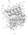
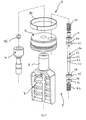
- an electromechanical device 800 for controlling the compression ratio of a variable volumetric ratio engine comprising for each cylinder a transmission device 1 and a piston 2.
- the mechanical transmission device 1 comprises in the lower part of the piston 2 a transmission member. transmission 3 secured to said piston and cooperating, on the one hand with a rolling guide device 4, and on the other hand with a toothed wheel 5.
- the gear 5 cooperates with a connecting rod 6 connected to a crankshaft 9 to achieve the transmission of the movement between the piston 2 and said crankshaft 9.
- the gear 5 cooperates opposite the transmission member 3 with another rack called control rack 7 whose vertical position relative to the engine block is driven by a control device 12.
- the control device 12 of the variable volumetric ratio engine comprises a control cylinder 8 which consists of a upper rod a cylinder 10, a lower cylinder rod 16, a cylinder piston 13 and a control rod 20.
- the electromechanical device 800 comprises mechanical means for transmitting the movement 801 between at least one electric motor 802 and at least one control rod 20 of a control device 12 for adjusting the vertical position of the control rack 7 of said motor. variable volumetric ratio.
- the electric motor 802 may be, for example, a stepper motor, a servomotor or a linear motor.
- the electromechanical device 800 comprises an electric motor 802 which includes a sensor for informing the engine management system on the angular position of said electric motor.
- the electromechanical device 800 comprises as many electric motors 802 as control rods 20, said control rods each having their own electric motor to adjust their vertical position.
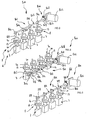
- the electromechanical device 800 comprises mechanical transmission means 801 which consist of at least one camshaft 803 which comprises at least one cam 804.
- the camshaft 803 may be, for example, mounted on bearings or bearings, not shown.
- cam 803 of camshaft 803 may be any or, for example, spiral to provide a constant relationship between the angular displacement of camshaft 803 and the linear displacement of the member. who is in contact with the cam.
- the electromechanical device 800 may comprise a camshaft 803 which is positioned above the cylinder head of the control cylinder (s) 8 of the control device 12 of the engine.
- the electromechanical device 800 may comprise a camshaft 803 which is positioned below the control jack (s) 8 of the control device 12 of the engine and inside the engine block of said engine.
- the electromechanical device 800 comprises a camshaft 803 which includes a sensor for informing the engine management system on the angular position of said camshaft.
- the electromechanical device 800 comprises a camshaft 803 which comprises a spring 805 of return rotation.
- the spring 805 may be, for example, a torsion spring consisting of a wire wound in a cylindrical shape or a spiral spring consisting of a spirally wound steel sheet.
- the electromechanical device 800 comprises a camshaft 803 which is connected to the electric motor 802 by intermediate transmission means 806.
- the intermediate transmission means 806 may consist, for example, of a toothed wheel 807 which cooperates with a worm 808.
- the intermediate transmission means 806 may consist, for example, of a gear system comprising at least two toothed wheels, or gears connected together by a chain or toothed pulleys interconnected by a belt. notched.
- the electromechanical device 800 comprising a camshaft 803 whose position is offset relative to that of the control rod or rods 20 of the control cylinder (s) 8.
- the camshaft 803 makes it possible to adjust the vertical position of the at least one control rod (s) 20 of the motor by means of at least one rocker 810 and 813.
- the rocker 810 and 813 can be made for example in foundry, forged steel or stamped sheet.
- Each rocker 810 has a hinge 811 provided near its center allowing it to pivot relative to the engine.
- One of the ends of the rocker arm 810 cooperates with at least one cam 804 of the camshaft 803 to adjust the angular position of said rocker arm, while the other end of said rocker arm cooperates with at least one control rod 20 to adjust the vertical position of said control rod.
- hinge 811 provided near the center of the rocker 810 may be, for example, a ball joint or a pivot connection.
- the hinge 811 which each rocker arm 810 comprises near its center, comprises an adjusting device 812 which makes it possible to fix the initial vertical position of at least one control rod 20 of a control cylinder 8 relative to in the initial vertical position of the other or other control rod (s) 20 of the other or the other control cylinder (s) 8 of the engine.
- the adjusting device 812 which comprises the hinge 811 arranged near the center of each rocker 810, consists of a thread which can be stopped in rotation, for example, by a counter nut, by gluing, by keying or by a "Nylstop" type brake.
- the electromechanical device 800 comprising a camshaft 803 which is positioned in the longitudinal axis of the control rod (s) 20 of the control jack (s) 8 and perpendicular to said axis, and acts on the vertical position of said control rod (s) 20 via at least one pusher 809.
- the pusher 809 comprises an adjustment device which makes it possible to fix the initial vertical position of at least one control rod 20 with respect to the initial vertical position of the other one or more control rods 20 of each cylinder. motor control 8.
- the adjustment device which comprises the pusher 809, consists of a thread that can be stopped in rotation, for example, by a lock nut, by gluing, by keying or by a "Nylstop" type brake.
- the electromechanical device 800 comprising a rocker 813 which comprises at one of its ends a hinge 814 allowing it to pivot relative to the engine on the one hand, and a surface 815 formed near its center and cooperating with at least one cam 804 of the camshaft 803 for adjusting the angular position of said rocker 813 on the other hand.
- the other end of said rocker 813 is provided to cooperate with at least one control rod 20 of the control cylinders 8 to adjust the vertical position of said control rod.
- hinge 814 that includes the rocker 813 at its end may be, for example, a ball joint or a pivot connection.
- the hinge 814 which includes the rocker 813 at its end and which allows said rocker arm to pivot relative to the engine, comprises an adjusting device 816 for fixing the initial vertical position of at least one control rod 20 relative to the initial vertical position of the other one or more control rods 20 of the engine.
- the adjusting device 816 which comprises the hinge 814 arranged at the end of the rocker 813, consists of a thread which can be stopped in rotation, for example, by a lock nut, by gluing, by keying or by a "Nylstop" type brake.
- electromechanical device 800 comprising mechanical means for transmitting the movement 801 between at least one electric motor 802 and at least one control rod 20.
- the mechanical transmission means of the movement 801 consist of at least one geared wheel 817 which comprises at least one toothed wheel 818 cooperating with a very small rack 819 mounted at the end of at least one control rod 20 of the engine.
- the geared wheel 817 may be, for example, mounted on bearings or not shown bearings.
- the geared wheel 817 may be, for example, mounted on bearings or not shown bearings.
- the electromechanical device 800 comprises a geared wheel shaft 817 which is connected to the electric motor 802 by intermediate transmission means 806.
- the intermediate transmission means 806 may consist, for example, of a toothed wheel 807 which cooperates with an endless screw 808 or of a gear system comprising at least two toothed wheels, of wheels toothed interconnected by a chain or toothed pulleys interconnected by a toothed belt.
- the rack of very small size 819 comprises an adjusting device for fixing the initial vertical position of at least one control rod 20 relative to the initial vertical position of the other or the other control rod (s) 20 of the engine.
- the adjustment device which comprises the rack of very small size 819, consists of a thread which can be stopped in rotation, for example, by a lock nut, by gluing, by keying or by a type of brake "Nylstop ".
- the electromechanical device 800 comprises either at least one pusher 809, at least one rocker 810, 813, or at least a very small rack 819, the adjustment of the initial vertical position of the control rods 20 of the engine relative to each other is performed during the assembly of the engine.
- the adjustment of the initial vertical position of the control rods 20 during the assembly of the engine is carried out either by measuring the altitude of the pistons 2 of the engine at the top dead center by means of a comparator or any other measuring instrument installed. in the spark plug well, either by measuring the volume of the combustion chambers of said engine when the pistons 2 of said engine are at top dead center.
- the device for adjusting the initial vertical position of the control rods 20 of the engine relative to each other may consist of an electric motor.
- each electric motor can be, for example, a linear piezoelectric motor.
- the adjustment of the initial vertical position of the engine control rods relative to each other can be effected by the engine running, or by measuring the effective pressure in the combustion chambers of the engine by means of appropriate sensors. or by deducing the effective pressure in the combustion chambers of the engine from the pressure measured in the upper chamber of the engine control cylinders by means of at least one pressure sensor.
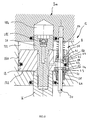
- control device 12 of the variable volumetric ratio engine comprising a control cylinder 8 which consists of an upper cylinder rod 10, a lower cylinder rod 16, a piston cylinder 13 and a rod control 20.
- the jack piston 13 comprises a peripheral swivel ring 180 which matches the spherical shape of said jack piston.
- the upper cylinder rod 10 has in its inner part and in its center a non-return valve 185 of leak compensation whose input is in communication with a chamber 184 formed in the cylinder head 300 of the control cylinder 8.
- the control rod 20 of the control jack 8 of the electromechanical device 800 has two shoulders 23 of small diameter for lifting two small diameter valves 21 located respectively in the upper chambers 121 and lower 122 of the control jack 8.
- the control rod 20 also comprises two shoulders 24 of large diameter which make it possible to lift two large diameter valves 25 which are also respectively in the upper chambers 121 and lower 122 of the control jack 8.
- the shoulders 23 of small diameter and the shoulders 24 of large diameter are positioned so that small diameter valves 21 are always open by the control rod 20 before the valves 25 of large diameter.
- the small diameter valves 21 comprise in their center a bore through which the control rod 20 passes, and a spherical contact zone 26 which cooperates with a conical contact zone 27 arranged in the large diameter valves 25.
- the bore formed in the center of the valves 21 of small diameter and which is traversed by the control rod 20 may comprise a groove containing a seal 28 can be toric elastic material, or in two parts one annular directly in contact with the control rod 20 and which has particular characteristics of wear resistance, and the other ring which has particular characteristics of elasticity and sealing and which always remains in contact with the bottom of said throat.
- the small diameter valves 21 can be made in two parts which are assembled by shrinking, gluing or crimping after mounting the seal.
- the small diameter valves 21 are held in contact with the large diameter valves 25 housed in the same chamber by means of springs 22 bearing on said small diameter valves 21 and on the wall of the chamber 121. , 122 of the control cylinder 8 in which they are housed on the other hand, said springs 22 also making it possible to keep the large diameter valves 25 in contact with the piston of the jack 13 of the control jack 8.
- the springs 22 may be, for example, of helical type and be mounted coaxially with the control rod 20.
- the small diameter valves 21 are held in contact with the large diameter valves 25 housed in the same chamber 121, 122 by means of at least one spring attached to the piston cylinder 13 and coming to bear on said small diameter valves, said spring also making it possible to keep the large diameter valves 25 in contact with the jack piston 13 of the control jack 8.
- the spring fixed on the jack piston 13 may consist of a sheet of steel of suitable shape or may be a torsion spring consisting of a winding of steel wire.
- the large diameter valves 25 have a smooth annular surface 29 which can be kept in contact with a smooth face respectively provided on the upper and lower faces of the piston of the cylinder 13 of the control jack 8 in order to seal with said piston.
- the large diameter valves 25 have centering means which keep them always centered on the control rod 20 along their longitudinal axis.
- the centering means which ensure the centering of large diameter valves on the control rod 20 leave sufficient radial mobility to said large diameter valves 25 so that the seal between said valves and the piston of the cylinder 13 of the control cylinder 8 is always achieved regardless of the orientation of said piston relative to the engine.
- the electromechanical device 800 comprises at least one control rod 20 which comprises at least one sensor for informing the engine management system on the vertical position of said rod.
- the electromechanical device 800 comprises at least one control rack 7 which comprises at least one sensor for informing the engine management system on the vertical position of said rack.
Landscapes
- Engineering & Computer Science (AREA)
- Mechanical Engineering (AREA)
- General Engineering & Computer Science (AREA)
- Chemical & Material Sciences (AREA)
- Combustion & Propulsion (AREA)
- Output Control And Ontrol Of Special Type Engine (AREA)
- Valve Device For Special Equipments (AREA)
- Transmission Devices (AREA)
Applications Claiming Priority (3)
| Application Number | Priority Date | Filing Date | Title |
|---|---|---|---|
| FR0600708A FR2896538B1 (fr) | 2006-01-26 | 2006-01-26 | Dispositif electromecanique de commande d'un moteur a rapport volumetrique variable |
| US76290406P | 2006-01-30 | 2006-01-30 | |
| PCT/FR2007/000147 WO2007085737A2 (fr) | 2006-01-26 | 2007-01-26 | Dispositif electromecanique de commande d'un moteur a rapport volumetrique variable |
Publications (2)
| Publication Number | Publication Date |
|---|---|
| EP1979595A2 EP1979595A2 (fr) | 2008-10-15 |
| EP1979595B1 true EP1979595B1 (fr) | 2012-10-24 |
Family
ID=36616980
Family Applications (1)
| Application Number | Title | Priority Date | Filing Date |
|---|---|---|---|
| EP07730865A Not-in-force EP1979595B1 (fr) | 2006-01-26 | 2007-01-26 | Dispositif electromecanique de commande d'un moteur a rapport volumetrique variable |
Country Status (10)
| Country | Link |
|---|---|
| US (1) | US8104437B2 (ja) |
| EP (1) | EP1979595B1 (ja) |
| JP (1) | JP5219838B2 (ja) |
| KR (1) | KR101257976B1 (ja) |
| CN (1) | CN101375043B (ja) |
| AU (1) | AU2007209222B2 (ja) |
| CA (1) | CA2640843A1 (ja) |
| ES (1) | ES2396450T3 (ja) |
| FR (1) | FR2896538B1 (ja) |
| WO (1) | WO2007085737A2 (ja) |
Families Citing this family (10)
| Publication number | Priority date | Publication date | Assignee | Title |
|---|---|---|---|---|
| FR2914951B1 (fr) | 2007-04-16 | 2012-06-15 | Vianney Rabhi | Dispositif electrohydraulique de pilotage en boucle fermee du verin de commande d'un moteur a taux de compression variable. |
| DE102010009907A1 (de) * | 2010-03-02 | 2011-09-08 | Daimler Ag | Hubkolbenmaschine |
| KR101305843B1 (ko) | 2011-11-30 | 2013-09-06 | 현대자동차주식회사 | 크랭크축리스 타입 내연기관 엔진 |
| EP2957748B1 (en) * | 2013-02-18 | 2017-04-05 | Nissan Motor Co., Ltd. | Control device and control method for internal combustion engine |
| EP2930329B1 (en) * | 2014-04-08 | 2016-12-28 | Gomecsys B.V. | An internal combustion engine including variable compression ratio |
| CN104612825B (zh) * | 2015-01-09 | 2023-11-17 | 范伟俊 | 具有可变压缩比的发动机 |
| FR3032234B1 (fr) * | 2015-01-30 | 2020-01-17 | Vianney Rabhi | Moteur thermique a transfert-detente et regeneration |
| FR3051838B1 (fr) * | 2016-05-24 | 2018-09-07 | MCE 5 Development | Dispositif de guidage a roulement d'un piston de combustion pour un moteur a taux de compression variable |
| US11187184B2 (en) * | 2019-03-29 | 2021-11-30 | Vianney Rabhi | Articulated plenum for transfer-expansion-regeneration combustion engine |
| CN114856838B (zh) * | 2022-04-02 | 2023-03-17 | 辽宁工程技术大学 | 一种自控调节汽油机用可变压缩比机构 |
Family Cites Families (12)
| Publication number | Priority date | Publication date | Assignee | Title |
|---|---|---|---|---|
| US4202300A (en) * | 1978-02-22 | 1980-05-13 | Frank Skay | Internal combustion engine |
| US4270495A (en) * | 1979-05-31 | 1981-06-02 | General Motors Corporation | Variable displacement piston engine |
| CN1053472A (zh) * | 1991-01-24 | 1991-07-31 | 牛保明 | 发动机 |
| JPH0754829A (ja) * | 1993-06-01 | 1995-02-28 | Sokan Shu | クランク装置 |
| US5406911A (en) * | 1993-08-12 | 1995-04-18 | Hefley; Carl D. | Cam-on-crankshaft operated variable displacement engine |
| FR2763097B1 (fr) | 1997-05-09 | 1999-09-03 | Vianney Paul Rabhi | Dispositif permettant de controler la position de la cremaillere de commande d'un moteur a cylindree variable |
| US6260532B1 (en) * | 1998-09-28 | 2001-07-17 | Edward Charles Mendler | Rigid crankshaft cradle and actuator |
| FR2786530B1 (fr) * | 1998-11-26 | 2001-01-19 | Vianney Rabhi | Dispositif de transmission mecanique pour moteur a cylindree variable |
| FR2827634B1 (fr) * | 2001-07-18 | 2003-10-03 | Vianney Rabhi | Perfectionnements apportes aux dispositifs de transmission mecanique pour moteur a cylindree variable |
| JP4416377B2 (ja) * | 2002-05-16 | 2010-02-17 | 日産自動車株式会社 | 内燃機関の制御装置 |
| JP2005163695A (ja) * | 2003-12-04 | 2005-06-23 | Nissan Motor Co Ltd | 内燃機関の圧縮比制御装置 |
| FR2867515B1 (fr) * | 2004-03-11 | 2006-06-02 | Vianney Rabhi | Dispositif de reglage pour moteur a rapport volumetrique variable |
-
2006
- 2006-01-26 FR FR0600708A patent/FR2896538B1/fr not_active Expired - Fee Related
-
2007
- 2007-01-26 KR KR1020087018299A patent/KR101257976B1/ko active IP Right Grant
- 2007-01-26 US US12/160,212 patent/US8104437B2/en active Active
- 2007-01-26 AU AU2007209222A patent/AU2007209222B2/en not_active Ceased
- 2007-01-26 CN CN2007800037678A patent/CN101375043B/zh not_active Expired - Fee Related
- 2007-01-26 ES ES07730865T patent/ES2396450T3/es active Active
- 2007-01-26 JP JP2008551826A patent/JP5219838B2/ja not_active Expired - Fee Related
- 2007-01-26 WO PCT/FR2007/000147 patent/WO2007085737A2/fr active Application Filing
- 2007-01-26 EP EP07730865A patent/EP1979595B1/fr not_active Not-in-force
- 2007-01-26 CA CA002640843A patent/CA2640843A1/fr not_active Abandoned
Also Published As
| Publication number | Publication date |
|---|---|
| WO2007085737A3 (fr) | 2007-09-20 |
| AU2007209222B2 (en) | 2011-07-21 |
| CN101375043A (zh) | 2009-02-25 |
| CA2640843A1 (fr) | 2007-08-02 |
| US8104437B2 (en) | 2012-01-31 |
| WO2007085737A2 (fr) | 2007-08-02 |
| US20090266337A1 (en) | 2009-10-29 |
| JP2009524767A (ja) | 2009-07-02 |
| FR2896538B1 (fr) | 2008-05-02 |
| AU2007209222A1 (en) | 2007-08-02 |
| CN101375043B (zh) | 2011-05-18 |
| KR20080098009A (ko) | 2008-11-06 |
| KR101257976B1 (ko) | 2013-04-24 |
| EP1979595A2 (fr) | 2008-10-15 |
| JP5219838B2 (ja) | 2013-06-26 |
| FR2896538A1 (fr) | 2007-07-27 |
| ES2396450T3 (es) | 2013-02-21 |
Similar Documents
| Publication | Publication Date | Title |
|---|---|---|
| EP1979595B1 (fr) | Dispositif electromecanique de commande d'un moteur a rapport volumetrique variable | |
| EP2655831B1 (fr) | Vanne tubulaire de commande d'un moteur à rapport volumétrique variable | |
| EP1740810B1 (fr) | Dispositif de reglage pour moteur a rapport volumetrique variable | |
| EP0460988B1 (fr) | Dispositif de commande par arbre à came et moyens transmetteurs d'efforts à galet | |
| FR2552820A1 (fr) | Culasse de cylindre pour moteur a combustion interne du type a double arbre a cames en tete | |
| EP3517756B1 (fr) | Moteur à taux de compression variable avec dispositif de levée de bille à vis | |
| EP0791129B1 (fr) | Pompe a pistons | |
| EP2281107A2 (fr) | Moteur pourvu d'une chambre a volume variable | |
| EP2279332B1 (fr) | Moteur a combustion interne | |
| FR2901567A1 (fr) | Ferme-porte encastrable. | |
| EP0560701A1 (fr) | Moteur à combustion interne, avec taux de compression et masse tournante du volant moteur ajustables en marche | |
| FR2987647A1 (fr) | Dispositif de filtre d'une soupape de commande d'un element de reglage d'arbre a came | |
| WO2013001173A1 (fr) | Actionneur a quart tournant a pignon non cylindrique et cremaillere complementaire | |
| FR2831221A1 (fr) | Dispositif de pompe hydraulique basse pression pour l'alimentation d'au moins un moteur hydraulique, notamment destine a equiper une bicyclette a entrainement hydraulique | |
| FR2562156A1 (fr) | Systeme de soupape pour un moteur a combustion interne | |
| FR2860027A1 (fr) | Ferme porte encastrable | |
| EP3004550A1 (fr) | Dispositif de transformation de mouvement et procédé correspondant | |
| WO2020002364A1 (fr) | Tendeur de courroie | |
| WO2008099104A2 (fr) | Agencement pour une colonne de direction electrique de vehicule automobile | |
| CA3053014A1 (fr) | Attelage articule pour dispositif d'etancheite pour piston | |
| FR2817907A1 (fr) | Dispositif de commande d'une soupape, et ensemble de controle de l'admission et de l'echappement comprenant un tel dispositif | |
| FR2984984A1 (fr) | Moteur a combustion ayant un piston muni d'une liaison a double roue | |
| WO2016059308A1 (fr) | Dispositif de reduction de roulis d'un groupe motopropulseur et vehicule automobile equipe dudit dispositif | |
| BE483654A (ja) |
Legal Events
| Date | Code | Title | Description |
|---|---|---|---|
| PUAI | Public reference made under article 153(3) epc to a published international application that has entered the european phase |
Free format text: ORIGINAL CODE: 0009012 |
|
| 17P | Request for examination filed |
Effective date: 20080731 |
|
| AK | Designated contracting states |
Kind code of ref document: A2 Designated state(s): AT BE BG CH CY CZ DE DK EE ES FI FR GB GR HU IE IS IT LI LT LU LV MC NL PL PT RO SE SI SK TR |
|
| 17Q | First examination report despatched |
Effective date: 20081125 |
|
| REG | Reference to a national code |
Ref country code: DE Ref legal event code: R079 Ref document number: 602007026245 Country of ref document: DE Free format text: PREVIOUS MAIN CLASS: F02D0015000000 Ipc: F02D0015020000 |
|
| GRAP | Despatch of communication of intention to grant a patent |
Free format text: ORIGINAL CODE: EPIDOSNIGR1 |
|
| RIC1 | Information provided on ipc code assigned before grant |
Ipc: F02D 15/02 20060101AFI20120426BHEP |
|
| DAX | Request for extension of the european patent (deleted) | ||
| GRAS | Grant fee paid |
Free format text: ORIGINAL CODE: EPIDOSNIGR3 |
|
| GRAA | (expected) grant |
Free format text: ORIGINAL CODE: 0009210 |
|
| AK | Designated contracting states |
Kind code of ref document: B1 Designated state(s): AT BE BG CH CY CZ DE DK EE ES FI FR GB GR HU IE IS IT LI LT LU LV MC NL PL PT RO SE SI SK TR |
|
| REG | Reference to a national code |
Ref country code: GB Ref legal event code: FG4D Free format text: NOT ENGLISH |
|
| REG | Reference to a national code |
Ref country code: CH Ref legal event code: EP |
|
| REG | Reference to a national code |
Ref country code: AT Ref legal event code: REF Ref document number: 581090 Country of ref document: AT Kind code of ref document: T Effective date: 20121115 |
|
| REG | Reference to a national code |
Ref country code: IE Ref legal event code: FG4D Free format text: LANGUAGE OF EP DOCUMENT: FRENCH |
|
| REG | Reference to a national code |
Ref country code: CH Ref legal event code: NV Representative=s name: RENTSCH PARTNER AG, CH |
|
| REG | Reference to a national code |
Ref country code: SE Ref legal event code: TRGR |
|
| REG | Reference to a national code |
Ref country code: DE Ref legal event code: R096 Ref document number: 602007026245 Country of ref document: DE Effective date: 20121227 |
|
| REG | Reference to a national code |
Ref country code: ES Ref legal event code: FG2A Ref document number: 2396450 Country of ref document: ES Kind code of ref document: T3 Effective date: 20130221 |
|
| REG | Reference to a national code |
Ref country code: AT Ref legal event code: MK05 Ref document number: 581090 Country of ref document: AT Kind code of ref document: T Effective date: 20121024 |
|
| REG | Reference to a national code |
Ref country code: NL Ref legal event code: VDEP Effective date: 20121024 |
|
| PG25 | Lapsed in a contracting state [announced via postgrant information from national office to epo] |
Ref country code: NL Free format text: LAPSE BECAUSE OF FAILURE TO SUBMIT A TRANSLATION OF THE DESCRIPTION OR TO PAY THE FEE WITHIN THE PRESCRIBED TIME-LIMIT Effective date: 20121024 Ref country code: FI Free format text: LAPSE BECAUSE OF FAILURE TO SUBMIT A TRANSLATION OF THE DESCRIPTION OR TO PAY THE FEE WITHIN THE PRESCRIBED TIME-LIMIT Effective date: 20121024 Ref country code: IS Free format text: LAPSE BECAUSE OF FAILURE TO SUBMIT A TRANSLATION OF THE DESCRIPTION OR TO PAY THE FEE WITHIN THE PRESCRIBED TIME-LIMIT Effective date: 20130224 |
|
| PG25 | Lapsed in a contracting state [announced via postgrant information from national office to epo] |
Ref country code: LV Free format text: LAPSE BECAUSE OF FAILURE TO SUBMIT A TRANSLATION OF THE DESCRIPTION OR TO PAY THE FEE WITHIN THE PRESCRIBED TIME-LIMIT Effective date: 20121024 Ref country code: PT Free format text: LAPSE BECAUSE OF FAILURE TO SUBMIT A TRANSLATION OF THE DESCRIPTION OR TO PAY THE FEE WITHIN THE PRESCRIBED TIME-LIMIT Effective date: 20130225 Ref country code: SI Free format text: LAPSE BECAUSE OF FAILURE TO SUBMIT A TRANSLATION OF THE DESCRIPTION OR TO PAY THE FEE WITHIN THE PRESCRIBED TIME-LIMIT Effective date: 20121024 Ref country code: GR Free format text: LAPSE BECAUSE OF FAILURE TO SUBMIT A TRANSLATION OF THE DESCRIPTION OR TO PAY THE FEE WITHIN THE PRESCRIBED TIME-LIMIT Effective date: 20130125 Ref country code: CY Free format text: LAPSE BECAUSE OF FAILURE TO SUBMIT A TRANSLATION OF THE DESCRIPTION OR TO PAY THE FEE WITHIN THE PRESCRIBED TIME-LIMIT Effective date: 20121024 Ref country code: PL Free format text: LAPSE BECAUSE OF FAILURE TO SUBMIT A TRANSLATION OF THE DESCRIPTION OR TO PAY THE FEE WITHIN THE PRESCRIBED TIME-LIMIT Effective date: 20121024 |
|
| PG25 | Lapsed in a contracting state [announced via postgrant information from national office to epo] |
Ref country code: AT Free format text: LAPSE BECAUSE OF FAILURE TO SUBMIT A TRANSLATION OF THE DESCRIPTION OR TO PAY THE FEE WITHIN THE PRESCRIBED TIME-LIMIT Effective date: 20121024 |
|
| BERE | Be: lapsed |
Owner name: RABHI, VIANNEY Effective date: 20130131 |
|
| PG25 | Lapsed in a contracting state [announced via postgrant information from national office to epo] |
Ref country code: BG Free format text: LAPSE BECAUSE OF FAILURE TO SUBMIT A TRANSLATION OF THE DESCRIPTION OR TO PAY THE FEE WITHIN THE PRESCRIBED TIME-LIMIT Effective date: 20130124 Ref country code: EE Free format text: LAPSE BECAUSE OF FAILURE TO SUBMIT A TRANSLATION OF THE DESCRIPTION OR TO PAY THE FEE WITHIN THE PRESCRIBED TIME-LIMIT Effective date: 20121024 Ref country code: CZ Free format text: LAPSE BECAUSE OF FAILURE TO SUBMIT A TRANSLATION OF THE DESCRIPTION OR TO PAY THE FEE WITHIN THE PRESCRIBED TIME-LIMIT Effective date: 20121024 Ref country code: DK Free format text: LAPSE BECAUSE OF FAILURE TO SUBMIT A TRANSLATION OF THE DESCRIPTION OR TO PAY THE FEE WITHIN THE PRESCRIBED TIME-LIMIT Effective date: 20121024 Ref country code: SK Free format text: LAPSE BECAUSE OF FAILURE TO SUBMIT A TRANSLATION OF THE DESCRIPTION OR TO PAY THE FEE WITHIN THE PRESCRIBED TIME-LIMIT Effective date: 20121024 |
|
| PG25 | Lapsed in a contracting state [announced via postgrant information from national office to epo] |
Ref country code: MC Free format text: LAPSE BECAUSE OF NON-PAYMENT OF DUE FEES Effective date: 20130131 Ref country code: RO Free format text: LAPSE BECAUSE OF FAILURE TO SUBMIT A TRANSLATION OF THE DESCRIPTION OR TO PAY THE FEE WITHIN THE PRESCRIBED TIME-LIMIT Effective date: 20121024 |
|
| PLBE | No opposition filed within time limit |
Free format text: ORIGINAL CODE: 0009261 |
|
| STAA | Information on the status of an ep patent application or granted ep patent |
Free format text: STATUS: NO OPPOSITION FILED WITHIN TIME LIMIT |
|
| 26N | No opposition filed |
Effective date: 20130725 |
|
| REG | Reference to a national code |
Ref country code: IE Ref legal event code: MM4A |
|
| PG25 | Lapsed in a contracting state [announced via postgrant information from national office to epo] |
Ref country code: BE Free format text: LAPSE BECAUSE OF NON-PAYMENT OF DUE FEES Effective date: 20130131 |
|
| REG | Reference to a national code |
Ref country code: DE Ref legal event code: R097 Ref document number: 602007026245 Country of ref document: DE Effective date: 20130725 |
|
| PG25 | Lapsed in a contracting state [announced via postgrant information from national office to epo] |
Ref country code: IE Free format text: LAPSE BECAUSE OF NON-PAYMENT OF DUE FEES Effective date: 20130126 |
|
| PG25 | Lapsed in a contracting state [announced via postgrant information from national office to epo] |
Ref country code: LT Free format text: LAPSE BECAUSE OF FAILURE TO SUBMIT A TRANSLATION OF THE DESCRIPTION OR TO PAY THE FEE WITHIN THE PRESCRIBED TIME-LIMIT Effective date: 20121024 |
|
| PG25 | Lapsed in a contracting state [announced via postgrant information from national office to epo] |
Ref country code: TR Free format text: LAPSE BECAUSE OF FAILURE TO SUBMIT A TRANSLATION OF THE DESCRIPTION OR TO PAY THE FEE WITHIN THE PRESCRIBED TIME-LIMIT Effective date: 20121024 |
|
| PG25 | Lapsed in a contracting state [announced via postgrant information from national office to epo] |
Ref country code: LU Free format text: LAPSE BECAUSE OF NON-PAYMENT OF DUE FEES Effective date: 20130126 Ref country code: HU Free format text: LAPSE BECAUSE OF FAILURE TO SUBMIT A TRANSLATION OF THE DESCRIPTION OR TO PAY THE FEE WITHIN THE PRESCRIBED TIME-LIMIT; INVALID AB INITIO Effective date: 20070126 |
|
| REG | Reference to a national code |
Ref country code: FR Ref legal event code: PLFP Year of fee payment: 10 |
|
| REG | Reference to a national code |
Ref country code: FR Ref legal event code: PLFP Year of fee payment: 11 |
|
| REG | Reference to a national code |
Ref country code: CH Ref legal event code: PCAR Free format text: NEW ADDRESS: BELLERIVESTRASSE 203 POSTFACH, 8034 ZUERICH (CH) |
|
| REG | Reference to a national code |
Ref country code: FR Ref legal event code: PLFP Year of fee payment: 12 |
|
| REG | Reference to a national code |
Ref country code: ES Effective date: 20180814 Ref legal event code: PC2A Owner name: MCE-5 DEVELOPMENT |
|
| REG | Reference to a national code |
Ref country code: CH Ref legal event code: PUEA Owner name: MCE-5 DEVELOPMENT, FR Free format text: FORMER OWNER: RABHI, VIANNEY, FR |
|
| REG | Reference to a national code |
Ref country code: GB Ref legal event code: 732E Free format text: REGISTERED BETWEEN 20180913 AND 20180919 |
|
| REG | Reference to a national code |
Ref country code: DE Ref legal event code: R082 Ref document number: 602007026245 Country of ref document: DE Representative=s name: SCHOPPE, ZIMMERMANN, STOECKELER, ZINKLER, SCHE, DE Ref country code: DE Ref legal event code: R081 Ref document number: 602007026245 Country of ref document: DE Owner name: MCE-5 DEVELOPMENT, FR Free format text: FORMER OWNER: RABHI, VIANNEY, LYON, FR Ref country code: DE Ref legal event code: R081 Ref document number: 602007026245 Country of ref document: DE Owner name: RABHI, VIANNEY, FR Free format text: FORMER OWNER: RABHI, VIANNEY, LYON, FR |
|
| PGFP | Annual fee paid to national office [announced via postgrant information from national office to epo] |
Ref country code: HU Payment date: 20190226 Year of fee payment: 17 Ref country code: CH Payment date: 20190123 Year of fee payment: 13 Ref country code: ES Payment date: 20190226 Year of fee payment: 13 Ref country code: IT Payment date: 20190124 Year of fee payment: 13 Ref country code: DE Payment date: 20190123 Year of fee payment: 13 |
|
| PGFP | Annual fee paid to national office [announced via postgrant information from national office to epo] |
Ref country code: SE Payment date: 20190121 Year of fee payment: 13 |
|
| REG | Reference to a national code |
Ref country code: DE Ref legal event code: R119 Ref document number: 602007026245 Country of ref document: DE |
|
| REG | Reference to a national code |
Ref country code: CH Ref legal event code: PL |
|
| REG | Reference to a national code |
Ref country code: SE Ref legal event code: EUG |
|
| GBPC | Gb: european patent ceased through non-payment of renewal fee |
Effective date: 20200126 |
|
| REG | Reference to a national code |
Ref country code: SE Ref legal event code: EUG |
|
| PG25 | Lapsed in a contracting state [announced via postgrant information from national office to epo] |
Ref country code: SE Free format text: LAPSE BECAUSE OF NON-PAYMENT OF DUE FEES Effective date: 20200127 Ref country code: DE Free format text: LAPSE BECAUSE OF NON-PAYMENT OF DUE FEES Effective date: 20200801 Ref country code: GB Free format text: LAPSE BECAUSE OF NON-PAYMENT OF DUE FEES Effective date: 20200126 |
|
| PG25 | Lapsed in a contracting state [announced via postgrant information from national office to epo] |
Ref country code: CH Free format text: LAPSE BECAUSE OF NON-PAYMENT OF DUE FEES Effective date: 20200131 Ref country code: LI Free format text: LAPSE BECAUSE OF NON-PAYMENT OF DUE FEES Effective date: 20200131 |
|
| PG25 | Lapsed in a contracting state [announced via postgrant information from national office to epo] |
Ref country code: IT Free format text: LAPSE BECAUSE OF NON-PAYMENT OF DUE FEES Effective date: 20200126 |
|
| REG | Reference to a national code |
Ref country code: ES Ref legal event code: FD2A Effective date: 20210604 |
|
| PG25 | Lapsed in a contracting state [announced via postgrant information from national office to epo] |
Ref country code: ES Free format text: LAPSE BECAUSE OF NON-PAYMENT OF DUE FEES Effective date: 20200127 |
|
| PGFP | Annual fee paid to national office [announced via postgrant information from national office to epo] |
Ref country code: FR Payment date: 20220119 Year of fee payment: 16 |
|
| PG25 | Lapsed in a contracting state [announced via postgrant information from national office to epo] |
Ref country code: FR Free format text: LAPSE BECAUSE OF NON-PAYMENT OF DUE FEES Effective date: 20230131 |