EP1979593B1 - Systeme de carburant de moteur a turbine a gaz dote d'une soupape doseuse de carburant - Google Patents
Systeme de carburant de moteur a turbine a gaz dote d'une soupape doseuse de carburant Download PDFInfo
- Publication number
- EP1979593B1 EP1979593B1 EP07763711.4A EP07763711A EP1979593B1 EP 1979593 B1 EP1979593 B1 EP 1979593B1 EP 07763711 A EP07763711 A EP 07763711A EP 1979593 B1 EP1979593 B1 EP 1979593B1
- Authority
- EP
- European Patent Office
- Prior art keywords
- fuel
- housing
- valve
- piston
- inlet port
- Prior art date
- Legal status (The legal status is an assumption and is not a legal conclusion. Google has not performed a legal analysis and makes no representation as to the accuracy of the status listed.)
- Expired - Fee Related
Links
Images


Classifications
-
- F—MECHANICAL ENGINEERING; LIGHTING; HEATING; WEAPONS; BLASTING
- F02—COMBUSTION ENGINES; HOT-GAS OR COMBUSTION-PRODUCT ENGINE PLANTS
- F02C—GAS-TURBINE PLANTS; AIR INTAKES FOR JET-PROPULSION PLANTS; CONTROLLING FUEL SUPPLY IN AIR-BREATHING JET-PROPULSION PLANTS
- F02C7/00—Features, components parts, details or accessories, not provided for in, or of interest apart form groups F02C1/00 - F02C6/00; Air intakes for jet-propulsion plants
- F02C7/22—Fuel supply systems
- F02C7/232—Fuel valves; Draining valves or systems
-
- F—MECHANICAL ENGINEERING; LIGHTING; HEATING; WEAPONS; BLASTING
- F02—COMBUSTION ENGINES; HOT-GAS OR COMBUSTION-PRODUCT ENGINE PLANTS
- F02C—GAS-TURBINE PLANTS; AIR INTAKES FOR JET-PROPULSION PLANTS; CONTROLLING FUEL SUPPLY IN AIR-BREATHING JET-PROPULSION PLANTS
- F02C9/00—Controlling gas-turbine plants; Controlling fuel supply in air- breathing jet-propulsion plants
- F02C9/26—Control of fuel supply
- F02C9/263—Control of fuel supply by means of fuel metering valves
Definitions
- the present invention relates generally to the field of gas turbine engines. More specifically, the present invention relates to gas turbine engine fuel systems and fuel metering valves thereof.
- gas turbine engine fuel systems which include a main fuel metering valve and another fuel metering valve referred to as a fuel shut-off valve. These valves operate to control flow of fuel from a fuel supply to a combustor where the fuel is combusted with pressurized air.
- the main fuel metering valve has the primary responsibility for metering fuel from the fuel supply to the combustor.
- the fuel shut-off valve serves as a back-up to the main fuel metering valve in the event that operation of the main fuel metering valve becomes impaired.
- Such fuel metering valves often have an operating position range with opposite end positions. In some cases, one end position results in a minimum flow condition and the other end position results in a maximum flow condition.
- US 3,713,290 A discloses a gas turbine engine fuel control.
- US 4,760,662 A discloses a hybrid fuel metering system.
- GB 2,199,648 A discloses a fuel nozzle assembly. This disclosure pertains to enhancements in the design of such fuel metering valves.
- One form of the present invention contemplates a gas turbine engine fuel system comprising a fuel metering valve as claimed in claim 1.
- the fuel metering valve is configured to move within an operating position range having a first end position for establishing a first fuel flow rate, a second end position for establishing a second fuel flow rate, and an intermediate position located between the first and second end positions for establishing a third fuel flow rate.
- the first and second fuel flow rates are both lower than the third fuel flow rate.
- the fuel metering valve is configured as an "axial" valve as claimed in claim 2.
- the fuel metering valve comprises a housing and a piston unit.
- the housing defines inlet and outlet ports and may define first and second outlet ports.
- the piston unit is positioned in the housing and may be coupled to a valve actuator to be moved thereby relative to the housing along an axis of the housing within an operating position range having first and second end positions and an intermediate position located therebetween to control flow of fuel from the inlet port to the first and second outlet ports.
- the fuel flow rates established by the first and second end positions are both higher than a fuel flow rate established by the intermediate position.
- the fuel metering valve is configured as a "rotary" valve.
- the fuel metering valve may comprise a housing, a fixed orifice plate positioned in and stationary relative to the housing and defining a fixed orifice, and a rotatable orifice plate positioned next to the fixed orifice plate and defining a rotatable orifice.
- the housing defines an inlet port and an outlet port.
- the rotatable orifice plate is coupled to the valve actuator to be rotated thereby relative to the housing and the fixed orifice plate within an operating position range having a first end position, a second end position, and an intermediate position located therebetween.
- the fixed and rotatable orifices cooperate to define a variable effective fuel flow area that is configured to control fuel flow from the inlet port to the outlet port and is either larger at both of the first and second end positions than at the intermediate position or smaller at both of the first and second end positions than at the intermediate position.
- FIG 1 there is illustrated a block diagram of a fuel system 10 of a gas turbine engine 12.
- Gas turbine engines contemplated herein are particularly applicable for, but not limited to, aircraft flight propulsion systems or industrial power plants.
- the gas turbine engine 12 includes a compressor for providing a pressurized working fluid, a combustor for burning a fuel and the pressurized working fluid to produce a hot exhaust gas and a turbine for extracting work from the hot exhaust gas.
- the present inventions are applicable with virtually all types and configurations of gas turbine engines.
- aircraft is generic and is meant to include helicopters, airplanes, missiles, unmanned space devices, transatmospheric vehicles and other substantially similar devices.
- gas turbine engines are also suited to be used in industrial applications, such as, for example, pumping sets for gas and oil transmission lines, electricity generation, and/or naval/sea based propulsion. Further, a gas turbine engine has application in other types of land based applications including propelling motor vehicles.
- the fuel system 10 includes a fuel metering valve 14 for metering the flow of fuel from a fuel supply 16 to a fuel dispenser 18 configured to dispense fuel into a combustor 20 of the engine 12 where fuel is combusted with pressurized air to produce a hot exhaust gas flow.
- the hot exhaust gas flow may be used directly to produce engine thrust or may be passed through a turbine to extract work to be used as shaft power.
- a valve actuator 22 under the control of a controller 24 is coupled to the valve 14 to move a movable component of the valve 14 within an operating position range.
- the valve actuator 22 may be, for example, any one or more of a hydraulic actuator, an electrical actuator, a pneumatic actuator, and a servo mechanism.
- the fuel metering valve 14 is configured to promote avoidance of a potential over-thrust condition of the engine 12. Avoidance of such potential engine over-thrust conditions may be particularly useful in connection with an outboard engine attached to a wing of an airplane to promote control of the airplane.
- the operating position range of the valve 14 includes opposite first and second end positions corresponding to the 0% and 100% valve positions, respectively, and includes a number of intermediate positions located therebetween.
- the first end position (0% position in FIG. 2 ) is used to establish a first fuel flow rate which, illustratively, is a zero flow rate. It is within the scope of this disclosure for the first fuel flow rate to be a non-zero, relatively low flow rate.
- the second end position (100% position in FIG. 2 ) is used to establish a second fuel flow rate which, illustratively, is a non-zero, relatively low flow rate.
- a second fuel flow rate which, illustratively, is a non-zero, relatively low flow rate.
- Such a low flow rate provides a "sustaining" flow of fuel to the combustor 20 in order to, for example, provide power for operating engine components or other components and/or reduce “windmill” drag that could potentially result from shutdown of the engine 12.
- the second fuel flow rate to be a zero flow rate.
- the maximum fuel flow rate, or third fuel flow rate, for the valve 14 is established at an intermediate position located between the first and second end positions. In one form of the present application this maximum fuel flow rate intermediate position happens to be at about the 68% position in FIG. 2 , although it is to be understood that this maximum fuel flow rate intermediate position could be at other intermediate positions depending on the desired flow characteristics for a particular application.
- the first and second fuel flow rates established by the first and second end positions of the valve 14 are thus both lower than the third fuel flow rate established by the intermediate position.
- Such a configuration of the fuel metering valve 14 promotes avoidance of a potential over-thrust condition of the engine 12 in the event of a performance irregularity associated with operation of the valve actuator 22.
- the performance irregularity may result, for example, from a loss of electrical power to the valve actuator 22 or from an electrical short circuit causing an over-supply of electrical power to the valve actuator 22.
- valve actuator 22 When the valve actuator 22 "fails” in these situations, it may drive the valve 14 to either one of the first and second end positions causing the valve to become “stuck” in that position.
- each of the flow rates established by the first and second end positions is a zero fuel flow rate or a relatively low, sustaining fuel flow rate and not a relatively high or maximum fuel flow rate, a potential over-thrust condition of the engine 12 is avoided.
- the fuel metering valve 14 is the only fuel metering valve of the system 10 located between the fuel supply 16 and the fuel dispenser 18. In particular, there is no fuel shut-off valve located between the fuel supply 16 and the fuel dispenser 18 since the valve 14 is configured to "handle" the aforementioned valve actuator performance irregularities.
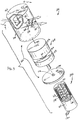
- a fuel metering valve 114 for use as the fuel metering valve 14 of the gas turbine engine fuel system 10.
- a valve actuator 122 for use as the valve actuator 22 of the system 10.
- the valve 114 is an "axial" valve and the valve actuator 122 is a solenoid valve actuator. While the valve actuator 122 will be described in one form with reference to a solenoid valve actuator it is fully contemplated herein that the valve actuator may take other forms including a hydraulic actuator, a pneumatic actuator and/or a servo mechanism.
- the valve 114 includes a housing 126 and a piston unit 128 captured in the housing 126 for axial movement relative to the housing 126 along an axis 130 within an operating position range having first and second end positions and intermediate positions located therebetween in response to movement of the actuator 122.
- the piston unit 128 is able to control flow of fuel from an inlet port 132 defined in the housing 126 to profiled first and second outlet ports 134, 136 defined in the housing 126.
- the housing 126 includes a sleeve 138 and end walls 140, 142 coupled to opposite ends of the sleeve 138.
- the sleeve 138 is formed to include the ports 132, 134, 136. Stops 144, 146 are coupled to the end walls 140, 142 for engagement with the piston unit 128 to establish the first and second end positions of the piston unit 128.
- the first outlet port 134 is generally T-shaped. As such, the port 134 has an axially extending base portion 148 and a circumferentially extending cross portion 150 which is located between the base portion 148 and the second outlet port 136.
- the first outlet port 134 is defined by an end surface 152 and a pair of convex side surfaces 154.
- the end surface 152 extends circumferentially but not axially and is located between the side surfaces 154 and the second outlet port 136.
- the side surfaces extend axially and circumferentially from one another to opposite ends of the end surface 152.
- the second outlet port 136 is generally oval-shaped. It is relatively small compared to the first outlet port 134. As such, it extends circumferentially along its major axis less than a majority of the length of the end surface 152.
- the piston unit 128 includes first and second pistons 156, 158 and a piston connector rod 160.
- the rod 160 connects the pistons 156, 158 to one another for axial movement together.
- the rod 160 spaces the pistons 156, 158 apart from one another to define a piston space 162 therebetween to allow communication between the inlet port 132 and the outlet ports 134, 136.
- the valve actuator 122 includes an actuator housing 164, a plunger 166, a coil 168, an actuator rod 170, electrical leads 172, and a return spring 174.
- the plunger 166 is positioned for axial movement in the housing 164 to cause extension and retraction of the rod 170 relative to the housing 164 in response to energization and de-energization of the coil 168 by the leads 172.
- the actuator rod 170 extends through an aperture 176 formed in the wall 140 and is coupled to the piston 158 so that such axial movement of the rod 170 causes corresponding axial movement of the piston unit 128 between its first and second end positions.
- the return spring 174 is positioned in the housing 164 to retract the rod 170 and thereby move the piston unit 128 to its first end position when the coil 168 is de-energized. While the piston unit 128 is described with reference to the valve actuator 122 it is contemplated herein that the piston unit 128 is moveable by other types of actuators.
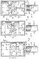
- the piston unit 128 positioned in its first end position in response to de-energization of the coil 168 due to, for example, a loss of electrical power to the actuator 122.
- the first piston 156 covers the entirety of both outlet ports 134, 136 so that communication between the inlet port 132 and the outlet ports 134, 136 is blocked. This results in a zero fuel flow rate in the system 10 and avoids a potential over-thrust condition of the engine 12.
- the piston unit 128 positioned in an intermediate, maximum flow rate position.
- the first piston 156 covers the entirety of the second outlet port 136 and the second piston 158 covers a part of the base portion 148 of the first outlet port 134.
- the cross portion 150 of the first outlet port 134 and a part of the base portion 148 is uncovered so as to allow communication between the inlet port 132 and the uncovered portion of the first outlet port 134 through the piston space 162.
- the piston unit 128 positioned in its second end position in response to high energization of the coil 168 due to, for example, a short circuit in the electrical circuitry that supplies electrical power to the leads 172.
- the second piston 158 covers the entirety of the first outlet port 134 whereas the second outlet port 136 is uncovered so that communication between the inlet port 132 and the second outlet port 136 is allowed through the piston space 162. This results in a relatively low, sustaining fuel flow rate in the system 10 so as to avoid a potential over-thrust condition of the engine 12.
- valve actuator 122 for use as the valve actuator 22 of the system 10.
- the valve 214 is a "rotary" valve and the valve actuator 222 is an electric motor. While the valve actuator 222 will be described in one form with reference to a electric motor it is fully contemplated herein that the valve actuator may take other forms including a hydraulic actuator, a pneumatic actuator and/or a servo mechanism.
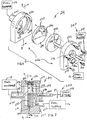
- the valve 214 includes a housing 226 defining an inlet port 232 and an outlet port 234.
- the inlet port 232 is configured to admit fuel from the fuel supply 16 into the housing 226 and the outlet port 234 is configured to discharge fuel from the housing 226 to flow to the fuel dispenser 18.
- the housing 226 includes first and second components 235, 236 coupled together by fasteners 237.
- a pair of relatively rotatable profiled orifice plates Captured between the housing components 235, 236 are a pair of relatively rotatable profiled orifice plates. Specifically, there are a fixed orifice plate 238 and a rotatable orifice plate 240 positioned within the housing 226.
- the fixed orifice plate 238 is mounted so as to be stationary relative to the housing 226.
- the fixed orifice plate 238 is positioned in a recessed portion 242 formed in the housing component 236.
- the fixed orifice plate 238 defines a notch 244 receiving an anti-rotation tab 246 coupled to the recessed portion 242 so that the plate 238 is prevented from rotating about a rotation axis 248 of the valve 214.
- the rotatable orifice plate 240 is mounted so as to be rotatable relative to the housing 226 and the fixed orifice plate 238.
- the rotatable orifice plate 240 is positioned in face-to-face contact with the fixed orifice plate 238 and is received in a recessed portion 250 formed in the housing member 235 for rotation therein about the axis 248.
- the actuator 222 is configured, for example, as an electric motor having a drive shaft 252 and a shaft rotator 254 for rotating the drive shaft 252.
- the drive shaft 252 extends through an aperture 276 defined in the housing 226 to rotate the rotatable orifice plate 240 about the axis 248.
- the fixed orifice plate 238 defines a fixed orifice 256 and the rotatable orifice plate 240 defines a rotatable orifice 258.
- the orifices 256, 258 cooperate to define an effective fuel flow area that is variable in size in response to rotation of the rotatable orifice plate 240 relative to the fixed orifice plate 238.
- the effective fuel flow area is smaller at both of the first and second end positions than at the intermediate position.
- the orifices 256, 258 are configured to provide the fuel flow characteristics such was represented in FIG. 2 .
- the rotatable orifice 258 is configured as a radially extending rectangular slot.
- the fixed orifice 256 has first and second end regions 260, 262 and an intermediate region 264 positioned between the first and second end regions 260, 262.
- Each of the first and second end regions 260, 262 has a radial thickness that is smaller than a radial thickness of the intermediate region 264.
- the fixed orifice 256 is defined by a first arcuate surface 266, a second arcuate surface 268, a convex surface 270, and a generally straight radial surface 272.
- Each of the second arcuate surface 268, the convex surface 270, and the radial surface 272 is positioned radially inwardly from the first arcuate surface 266.
- the radial surface 272 is positioned between the second arcuate surface 268 and the convex surface 270 and extends radially but not circumferentially.
- the first end region 260 is defined between the first arcuate surface 266 and the convex surface 270.
- the second end region 260 is defined between the first arcuate surface 266 and the second arcuate surface 268.
- the intermediate region 264 is defined between the first arcuate surface 266, the convex surface 270, and the radial surface 272.
- the rotatable orifice 258 positioned in the first end position in response, for example, to a loss of electrical power to the actuator 222.
- the rotatable orifice 258 does not overlap any part of the fixed orifice 256.
- the effective fuel flow area is closed so as to produce a zero fuel flow rate in the system 10.
- Such a configuration avoids a potential over-thrust condition of the engine 12.
- the rotatable orifice 258 positioned in an intermediate, maximum flow rate position. In this position, the rotatable orifice 258 overlaps the intermediate region 264 of the fixed orifice 256. This results in a maximum size effective fuel flow area and thus a maximum fuel flow rate from the fuel supply 16 through the housing 226 to the fuel dispenser 18. If one of the aforementioned actuator fault modes occurs, the rotatable orifice 258 will be driven away from this intermediate, maximum flow rate position to one of the end positions. As such, a potential over-thrust condition of the engine 12 is avoided.
- the rotatable orifice 258 positioned in the second end position in response, for example, to a short circuit in the electrical circuitry that supplies electrical power to the actuator 222.
- the rotatable orifice 258 overlaps the second end region 262. This results in a relatively small effective fuel flow area and thus a relatively low, sustaining fuel flow rate in the system 10 so as to avoid a potential engine over-thrust condition.
- the fuel system 310 includes a main fuel metering valve 314 and another fuel metering valve configured as a fuel shut-off valve 315.
- the main fuel metering valve 314 has the primary responsibility for metering flow of fuel from a fuel supply 316 to a fuel dispenser 318 configured to dispense fuel into a combustor 320 of the engine 312 where fuel is combusted with pressurized air to produce the hot exhaust gas flow.
- the fuel shut-off valve 315 serves to meter the fuel flow if operation of the main fuel metering valve 314 becomes impaired. As such, the fuel shut-off valve 315 is normally in a maximum flow position and operates to restrict fuel flow when it is activated to back up the main fuel metering valve 314.
- valve actuators 314, 315 There are separate valve actuators for the valves 314, 315.
- a valve actuator 322 under the control of a controller 324 is coupled to the valve 314 to move the valve 314 within its operating position range.
- a valve actuator 323 under the control of the controller 324 is coupled to the valve 315 to move movable components of the valve 315 within its operating position range.
- Each actuator 322, 323 may be, for example, any one or more of a hydraulic actuator, an electrical actuator, a pneumatic actuator, and a servo mechanism.
- the operating position range of the valve 315 includes opposite first and second end positions corresponding to the 0% and 100% valve positions, respectively, and includes a number of intermediate positions located therebetween.
- the first end position (0% position in FIG. 13 ) is used to establish a first fuel flow rate which, illustratively, is a relatively high, maximum fuel flow rate.
- the second end position (100% position in FIG. 13 ) is used to establish a second fuel flow rate which, illustratively, is the relatively high, maximum fuel flow rate.
- the minimum fuel flow rate, or third fuel flow rate, for the valve 315 is established at an intermediate position located between the first and second end positions.
- This minimum fuel flow rate intermediate position happens to be at about the 80% position in FIG. 13 , although it is to be understood that this minimum fuel flow rate intermediate position could be at other intermediate positions depending on the desired flow characteristics for a particular application.
- the minimum fuel flow rate is a zero flow rate, although it is within the scope of this disclosure for the minimum fuel flow rate to be a relatively low, non-zero fuel flow rate.
- the first and second fuel flow rates established by the first and second end positions of the valve 315 are thus both higher than the third fuel flow rate established by the intermediate position.
- Such a configuration of the fuel shut-off valve 315 promotes control of the fuel flow by the main metering valve 314 in the event of a performance irregularity associated with operation of the valve actuator 323.
- the performance irregularity may result, for example, from a loss of electrical power to the valve actuator 323 or from an electrical short circuit causing an over-supply of electrical power to the valve actuator 323.
- valve actuator 323 When the valve actuator 323 "fails” in these situations, it may drive the valve 315 to either one of the first and second end positions causing the valve to become “stuck” in that position.
- the main fuel metering valve 314 since each of the fuel flow rates established by the first and second end positions is a relatively high or maximum fuel flow rate and not a relatively low or zero fuel flow rate, the main fuel metering valve 314 is able to retain primary control for metering fuel flow from the fuel supply 316 to the fuel dispenser 318.
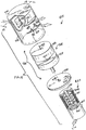
- a fuel shut-off valve 415 for use as the fuel shut-off valve 315 of the gas turbine engine fuel system 310.
- valve actuator 423 for use as the valve actuator 323 of the system 310.
- the valve 415 is an "axial" valve and the valve actuator 423 is a solenoid valve actuator.
- the valve 415 includes a housing 426 and a piston unit 428 captured in the housing 426 for axial movement relative to the housing 426 along an axis 430 within an operating position range having first and second end positions and intermediate positions located therebetween in response to movement of the actuator 423.
- the piston unit 428 is able to control flow of fuel from an inlet port 432 defined in the housing 426 to profiled first and second outlet ports 434, 436 defined In the housing 426.
- the housing 426 includes a sleeve 438 and end walls 440, 442 coupled to opposite ends of the sleeve 438.
- the sleeve 438 is formed to include the ports 432, 434, 436. Stops 444, 446 are coupled to the end walls 440, 442 for engagement with the piston unit 428 to establish the first and second end positions of the piston unit 428.
- the first outlet port 434 is generally T-shaped. As such, the port 434 has an axially extending base portion 448 and a circumferentially extending cross portion 450. The base portion 448 is located between the cross portion 450 and the second outlet port 436.
- the first outlet port 434 is defined by an end surface 452 and a pair of convex side surfaces 454.
- the end surface 452 extends circumferentially but not axially and is located between the side surfaces 454.
- the side surfaces 454 extend axially and circumferentially from one another to opposite ends of the end surface 452 and are located between the end surface 452 and the second outlet port 436.
- the second outlet port 436 is generally oval-shaped.
- the second outlet port 436 extends circumferentially along its major axis substantially the length of the end surface 452.
- the piston unit 428 includes first and second pistons 456, 458 and a piston connector rod 460.
- the rod 460 connects the pistons 456, 458 to one another for axial movement together.
- the rod 460 spaces the pistons 456, 458 apart from one another to define a piston space 462 therebetween to allow communication between the inlet port 432 and the outlet ports 434, 436.
- the valve actuator 423 includes an actuator housing 464, a plunger 466, a coil 468, an actuator rod 470, electrical leads 472, and a return spring 474.
- the plunger 466 is positioned for axial movement in the housing 464 to cause extension and retraction of the rod 470 relative to the housing 464 in response to energization and de-energization of the coil 468 by leads 472.
- the actuator rod 470 extends through an aperture 476 formed in the wall 440 and is coupled to the piston 458 so that such axial movement of the rod 470 causes corresponding axial movement of the piston unit 428 between its first and second end positions.
- the return spring 474 is positioned in the housing 464 to retract the rod 470 and thereby move the piston unit 428 to its first end position when the coil 468 is de-energized.
- the piston unit 428 positioned in its first end position in response to de-energization of the coil 468 due to, for example, a loss of electrical power to the actuator 422.
- the first piston 456 blocks communication between the inlet port 432 and the second outlet port 436.
- the pistons 456, 458 are positioned to allow communication between the inlet port 432 and the first outlet port 434 through the piston space 462 defined between the pistons 456, 458. This results in a maximum fuel flow rate through the valve 415 so as to allow the main fuel metering valve 414 to retain control of metering fuel flow in the system 310.
- the piston unit 428 positioned in an intermediate, zero fuel flow rate position.
- the first piston 456 covers the entirety of the second outlet port 436 and the second piston 458 covers entirety of the first outlet port 434 such that the first and second pistons 456, 458 cooperate to block communication between the inlet port 432 and the first and second outlet ports 434, 436.
- the piston unit 428 positioned in its second end position in response to high energization of the coil 468 due to, for example, a short circuit in the electrical circuitry that supplies electrical power to the leads 472.
- the second piston 458 blocks communication between the inlet port 432 and the first outlet port 434.
- the pistons 456, 458 are positioned to allow communication between the inlet port 432 and the second outlet port 436 through the piston space 462. This results in a maximum fuel flow rate through the valve 415 so as to allow the main fuel metering valve 414 to retain control of metering fuel flow in the system 310.
- the fuel shut-off valve 315 prefferably configured as a rotary valve.
- the valve has fixed and rotatable orifice plates similar to plates 238, 240 except that the fixed orifice is profiled to produce the flow characteristics of FIG. 13 .
- the radial thickness of the intermediate region of the fixed orifice formed in the fixed orifice plate may be more narrow than the radial thickness of each of the first and second end regions of the fixed orifice.
Landscapes
- Engineering & Computer Science (AREA)
- Chemical & Material Sciences (AREA)
- Combustion & Propulsion (AREA)
- Mechanical Engineering (AREA)
- General Engineering & Computer Science (AREA)
- Feeding And Controlling Fuel (AREA)
- Electrically Driven Valve-Operating Means (AREA)
- Measuring Volume Flow (AREA)
Claims (22)
- Système d'alimentation en carburant pour moteur à turbine à gaz destiné à fournir du carburant à une chambre de combustion à divers débits, le système comprenant :une soupape de dosage de carburant (14; 114 ; 214) configurée pour se déplacer à l'intérieur d'une plage de position de fonctionnement présentant une première position d'extrémité permettant d'établir un premier débit de carburant vers la chambre de combustion (20), une deuxième position d'extrémité permettant d'établir un deuxième débit de carburant vers la chambre de combustion (20), et une position intermédiaire située entre les première et deuxième positions d'extrémité et permettant d'établir un troisième débit de carburant vers la chambre de combustion (20),caractérisé en ce que les premier et deuxième débits de carburant sont tous les deux inférieurs au troisième débit de carburant.
- Système d'alimentation en carburant pour moteur à turbine à gaz destiné à fournir du carburant à une chambre de combustion à divers débits, le système comprenant :une soupape de dosage de carburant (315 ; 415), la soupape de dosage de carburant comprenant un logement (426) et une unité piston (428), le logement définissant des orifices d'entrée et de sortie (432, 434, 436), l'unité piston (428) étant positionnée dans le logement (426) et étant mobile par rapport au logement (426) le long d'un axe (430) du logement (426) afin de commander un écoulement de carburant entre les orifices d'entrée et de sortie (432, 434, 436) ;dans lequel la soupape de dosage de carburant (315 ; 415) est configurée pour déplacer l'unité piston (428) par rapport au logement à l'intérieur d'une plage de position de fonctionnement présentant une première position d'extrémité permettant d'établir un premier débit de carburant vers la chambre de combustion (320), une deuxième position d'extrémité permettant d'établir un deuxième débit de carburant vers la chambre de combustion (320), et une position intermédiaire située entre les première et deuxième positions d'extrémité et permettant d'établir un troisième débit de carburant vers la chambre de combustion (320) ; etdans lequel les premier et deuxième débits de carburant sont tous les deux supérieurs au troisième débit de carburant.
- Système selon la revendication 1 ou 2, comprenant en outre un actionneur de soupape (22 ; 122 ; 323 ; 423 ; 222) couplé à la soupape (14 ; 114 ; 315 ; 415 ; 214) et configuré pour déplacer la soupape (14; 114; 315; 415) vers la première position d'extrémité en réaction à une première irrégularité de performance associée au fonctionnement de l'actionneur de soupape (22 ; 122 ; 323 ; 423 ; 222) et vers la deuxième position d'extrémité en réaction à une deuxième irrégularité de performance associée au fonctionnement de l'actionneur de soupape.
- Système selon la revendication 1, comprenant en outre une alimentation de carburant (16) et un distributeur de carburant (18) permettant de distribuer du carburant vers une chambre de combustion (20), dans lequel la soupape de dosage de carburant (14; 114; 214) est l'unique soupape de dosage de carburant positionnée entre l'alimentation de carburant (16) et le distributeur de carburant (18).
- Système selon la revendication 2, comprenant en outre une alimentation de carburant (316), un distributeur de carburant (318) permettant de distribuer du carburant vers une chambre de combustion (320), et une soupape principale de dosage de carburant (314), dans lequel la soupape de dosage de carburant (315 ; 415) est un robinet coupe-feu qui est positionné entre l'alimentation de carburant (316) et le distributeur de carburant (318) en même temps que la soupape principale de dosage de carburant (314).
- Système selon la revendication 1, dans lequel :la soupape (114) comprend un logement (126) et des premier et deuxième pistons (156, 158) positionnés dans le logement (126) et couplés l'un à l'autre afin de définir un espace de piston (162) entre ceux-ci, le logement (126) est formé de manière à inclure un orifice d'entrée (132) afin d'admettre du carburant dans l'espace de piston (162) et des premier et deuxième orifices de sortie (134, 136) espacés l'un par rapport à l'autre de manière axiale afin de refouler du carburant à partir de l'espace de piston (162), et les premier et deuxième pistons (156, 158) sont mobiles de manière axiale à l'intérieur du logement (126) afin de recouvrir et de découvrir au moins des parties des premier et deuxième orifices de sortie (134, 136) afin de faire varier un écoulement de carburant à partir de l'orifice d'entrée (132) vers les premier et deuxième orifices de sortie (134, 136) en passant par l'espace de piston (162).
- Système selon la revendication 2, dans lequel :l'unité piston (428) comprend des premier et deuxième pistons (456, 458) positionnés dans le logement (426) et couplés l'un à l'autre afin de définir un espace de piston (462) entre ceux-ci, le logement (426) étant formé de manière à inclure un orifice d'entrée (432) afin d'admettre du carburant dans l'espace de piston (462) et des premier et deuxième orifices de sortie (434, 436) espacés l'un par rapport à l'autre de manière axiale afin de refouler du carburant à partir de l'espace de piston (462), et les premier et deuxième pistons (456, 458) étant mobiles de manière axiale à l'intérieur du logement (426) afin de recouvrir et découvrir au moins des parties des premier et deuxième orifices de sortie (434, 436) afin de faire varier un écoulement de carburant à partir de l'orifice d'entrée (432) vers les premier et deuxième orifices de sortie (434, 436) en passant par l'espace de piston (462).
- Système selon la revendication 1, dans lequel
la soupape (214) comprend des premier et deuxième diaphragmes (238, 240) rotatifs l'un par rapport à l'autre, le premier diaphragme (238) définit une première lumière (256), le deuxième diaphragme (240) définit une deuxième lumière (258), et les premier et deuxième diaphragmes (238, 240) sont positionnés à proximité l'un de l'autre de sorte que les première et deuxième lumières (256, 258) coopèrent pour définir une section effective d'écoulement de carburant qui est de taille variable en réaction à une rotation l'un par rapport à l'autre des premier et deuxième diaphragmes (238, 240) entre la première position d'extrémité, la deuxième position d'extrémité, et la position intermédiaire. - Système selon la revendication 1, comprenant en outre un actionneur de soupape (122), et dans lequel la soupape de dosage de carburant (114) comprend un logement (126) et une unité piston (128), le logement définissant un orifice d'entrée (132) et des premier et deuxième orifices de sortie (134, 136), l'unité piston (128) étant positionnée dans le logement (126) et étant couplée à l'actionneur de soupape (122) afin d'être déplacée grâce à celui-ci par rapport au logement (126) le long d'un axe (130) du logement (126) à l'intérieur de ladite plage de position de fonctionnement afin de commander un écoulement de carburant à partir de l'orifice d'entrée (132) vers les premier et deuxième orifices de sortie (134, 136) auxdits premier, deuxième et troisième débits.
- Système selon la revendication 2, comprenant en outre un actionneur de soupape (423), et dans lequel le logement définit un orifice d'entrée (432) et des premier et deuxième orifices de sortie (434, 436), l'unité piston (428) étant couplée à l'actionneur de soupape (423) à déplacer par rapport au logement (426) le long de l'axe (430) du logement (426) à l'intérieur de ladite plage de position de fonctionnement afin de commander un écoulement de carburant à partir de l'orifice d'entrée (432) vers les premier et deuxième orifices de sortie (434, 436) avec lesdits premier, deuxième et troisième débits.
- Système selon la revendication 9 ou 10, dans lequel l'actionneur de soupape (122 ; 423) est configuré pour déplacer l'unité piston (128 ; 428) de manière axiale vers la première position d'extrémité en réaction à une première irrégularité de performance associée au fonctionnement de l'actionneur de soupape (122 ; 423) et pour déplacer l'unité piston de manière axiale vers la deuxième position d'extrémité en réaction à une deuxième irrégularité de performance associée au fonctionnement de l'actionneur de soupape (122 ; 423).
- Système selon la revendication 9 ou la revendication 10, dans lequel l'unité piston (128 ; 428) comprend des premier et deuxième pistons (156, 158 ; 456, 458) couplés l'un à l'autre afin de se déplacer ensemble pour recouvrir et découvrir au moins des parties des premier et deuxième orifices de sortie (134, 136 ; 434, 436).
- Système selon la revendication 12, lorsqu'elle est dépendante de la revendication 9, dans lequel :le premier orifice de sortie (134) est essentiellement en forme de T de manière à comprendre une partie base à extension axiale (148) et une partie transversale à extension circonférentielle (150), dans la première position d'extrémité, le premier piston (156) bloque la communication entre l'orifice d'entrée (132) et la totalité des premier et deuxième orifices de sortie (134, 136), dans la position intermédiaire, les premier et deuxième pistons (156, 158) sont positionnés afin de permettre une communication entre l'orifice d'entrée (134) et la partie transversale (150) à travers un espace de piston (162) défini entre les premier et deuxième pistons (156, 158), le premier piston (156) bloque la communication entre l'orifice d'entrée (132) et la totalité du deuxième orifice de sortie (136), et le deuxième piston (158) bloque la communication entre l'orifice d'entrée (132) et au moins une partie de la partie base (148), et, dans la deuxième position d'extrémité, les premier et deuxième pistons (156, 158) sont positionnés afin de permettre la communication entre l'orifice d'entrée (132) et le deuxième orifice de sortie (136) à travers l'espace de piston (162), et le deuxième piston (158) bloque la communication entre l'orifice d'entrée (132) et la totalité du premier orifice de sortie (134).
- Système selon la revendication 12, lorsqu'elle est dépendante de la revendication 10, dans lequel :le premier orifice de sortie (434) est essentiellement en forme T de manière à comprendre une partie base à extension axiale (448) et une partie transversale à extension circonférentielle (450), dans la première position d'extrémité, les premier et deuxième pistons (456, 458) sont positionnés afin de permettre la communication entre l'orifice d'entrée (432) et la partie transversale (450) à travers un espace de piston (462) défini entre les premier et deuxième pistons (456, 458), et le premier piston (456) bloque la communication entre l'orifice d'entrée (432) et la totalité du deuxième orifice de sortie (436), dans la position intermédiaire, le premier piston (456) bloque la communication entre l'orifice d'entrée (432) et la totalité du deuxième orifice de sortie (436), et le deuxième piston (458) bloque la communication entre l'orifice d'entrée (432) et la totalité du premier orifice de sortie (434), et, dans la deuxième position d'extrémité, les premier et deuxième pistons (456, 458) sont positionnés afin de permettre la communication entre l'orifice d'entrée (432) et le deuxième orifice de sortie (436) à travers l'espace de piston (462), et le deuxième piston (458) bloque la communication entre l'orifice d'entrée (432) et la totalité du premier orifice de sortie (434).
- Système selon la revendication 9 ou la revendication 10, dans lequel :le premier orifice de sortie (134 ; 434) est défini grâce à une surface terminale (152 ; 452) et des première et deuxième surfaces latérales convexes (154 ; 454) formées dans ledit logement (126 ; 426), la surface terminale (152 ; 452) s'étend de manière circonférentielle mais non axiale, les surfaces latérales (154 ; 454) s'étendent de manière axiale et circonférentielle l'une par rapport à l'autre vers la surface terminale (152 ; 452), et soit la surface terminale (152) est située de manière axiale entre le deuxième orifice de sortie (136) et les première et deuxième surfaces latérales (154), et le deuxième orifice de sortie (136) s'étend de manière circonférentielle sur moins d'une majorité de la longueur de la surface terminale (152), soit les première et deuxième surfaces latérales (454) sont situées de manière axiale entre le deuxième orifice de sortie (436) et la surface terminale (452), et le deuxième orifice de sortie (436) s'étend de manière circonférentielle sur essentiellement la longueur de la surface terminale (452).
- Système selon la revendication 9 ou la revendication 10, dans lequel :le premier orifice de sortie (134) est essentiellement en forme de T et le deuxième orifice de sortie (136) est essentiellement de forme ovale, le premier orifice de sortie (134) essentiellement en forme de T comprend une partie transversale à extension circonférentielle (150) et une partie base à extension axiale (148), et soit la partie transversale (150) est positionnée entre la partie base (148) et le deuxième orifice de sortie (134) soit la partie base est positionnée entre la partie transversale et le deuxième orifice de sortie.
- Système selon la revendication 1, comprenant en outre un actionneur de soupape (222), et dans lequel la soupape de dosage de carburant comprend un logement (226), un diaphragme fixe (238) positionné dans le logement (226) et immobile par rapport à celui-ci et définissant une lumière fixe (256), et un diaphragme rotatif (240) positionné à proximité du diaphragme fixe (238) et définissant une lumière rotative (258), le logement (226) définissant un orifice d'entrée (232) et un orifice de sortie (234), le diaphragme rotatif (240) étant couplé à l'actionneur de soupape (222) afin d'être entrainé en rotation grâce à celui-ci par rapport au logement (226) et le diaphragme fixe (238) à l'intérieur de ladite plage de position de fonctionnement, les lumières fixe et rotative (256, 258) coopérant pour définir une section effective d'écoulement de carburant variable qui est configurée pour commander un écoulement de carburant à partir de l'orifice d'entrée (232) vers l'orifice de sortie (234) et qui est plus grande au niveau des deux parmi les première et deuxième positions d'extrémité qu'au niveau de la position intermédiaire ou bien plus petite au niveau des deux parmi les première et deuxième positions d'extrémité qu'au niveau de la position intermédiaire.
- Système selon la revendication 17, dans lequel l'actionneur de soupape (222) est configuré pour faire tourner le diaphragme rotatif (240) vers la première position d'extrémité en réaction à une première irrégularité de performance associée au fonctionnement de l'actionneur de soupape (222) et pour faire tourner le diaphragme rotatif (240) vers la deuxième position d'extrémité en réaction à une deuxième irrégularité de performance associée au fonctionnement de l'actionneur de soupape (222).
- Système selon la revendication 17, dans lequel la section effective d'écoulement de carburant est plus petite au niveau des deux parmi les première et deuxième positions d'extrémité qu'au niveau de la position intermédiaire.
- Système selon la revendication 17, dans lequel :la lumière rotative (258) est configurée en tant que fente rectangulaire à extension radiale formée dans le diaphragme rotatif (240), la lumière fixe (256) comprend des première et deuxième régions d'extrémité (260) et une région intermédiaire (264) située entre celles-ci, et les première et deuxième régions d'extrémité (260) présentent une épaisseur radiale qui est inférieure à une épaisseur radiale de la région intermédiaire (264).
- Système selon la revendication 20, dans lequel :la lumière fixe (256) est définie grâce à une première surface arquée (266), une deuxième surface arquée (268) positionnée radialement vers l'intérieur par rapport à la première surface arquée (266), une surface convexe (270) positionnée radialement vers l'intérieur par rapport à la première surface arquée (266), et une surface radiale essentiellement droite (272), qui est positionnée radialement vers l'intérieur par rapport à la première surface arquée (266), est positionnée entre la deuxième surface arquée (268) et la surface convexe (270), et s'étend de manière radiale mais non circonférentielle, la première région d'extrémité (260) est définie entre la première surface arquée (266) et la surface convexe (270), la deuxième région d'extrémité (260) est définie entre les première et deuxième surfaces arquées (266, 268), et la région intermédiaire (264) est définie entre la première surface arquée (266), la surface convexe (270), et la surface radiale (272).
- Système selon la revendication 1, dans lequel la soupape de dosage de carburant (214) comprend un logement (226) définissant un orifice d'entrée (232) et un orifice de sortie (234), l'orifice d'entrée (232) étant configuré pour admettre du carburant en provenance d'une alimentation de carburant jusque dans le logement (226) et les premier, deuxième et troisième débits de carburant vers la chambre de combustion (20) étant refoulés à partir du logement (226) à travers l'orifice de sortie (232).
Applications Claiming Priority (2)
| Application Number | Priority Date | Filing Date | Title |
|---|---|---|---|
| US76512606P | 2006-02-03 | 2006-02-03 | |
| PCT/US2007/003168 WO2007092456A2 (fr) | 2006-02-03 | 2007-02-05 | Systeme de carburant de moteur a turbine a gaz dote d'une soupape doseuse de carburant |
Publications (3)
| Publication Number | Publication Date |
|---|---|
| EP1979593A2 EP1979593A2 (fr) | 2008-10-15 |
| EP1979593A4 EP1979593A4 (fr) | 2010-03-17 |
| EP1979593B1 true EP1979593B1 (fr) | 2017-12-06 |
Family
ID=38345752
Family Applications (1)
| Application Number | Title | Priority Date | Filing Date |
|---|---|---|---|
| EP07763711.4A Expired - Fee Related EP1979593B1 (fr) | 2006-02-03 | 2007-02-05 | Systeme de carburant de moteur a turbine a gaz dote d'une soupape doseuse de carburant |
Country Status (3)
| Country | Link |
|---|---|
| US (1) | US7526911B2 (fr) |
| EP (1) | EP1979593B1 (fr) |
| WO (1) | WO2007092456A2 (fr) |
Families Citing this family (20)
| Publication number | Priority date | Publication date | Assignee | Title |
|---|---|---|---|---|
| JP4840340B2 (ja) * | 2007-11-28 | 2011-12-21 | トヨタ自動車株式会社 | 車両の制御装置 |
| GB0820410D0 (en) * | 2008-11-07 | 2008-12-17 | Goodrich Control Sys Ltd | Engine relight method |
| US9217376B2 (en) * | 2008-11-13 | 2015-12-22 | Sikorsky Aircraft Corporation | Multi-mode adaptive fail-fixed system for FADEC controlled gas turbine engines |
| US9140190B2 (en) | 2012-06-06 | 2015-09-22 | Honeywell International Inc. | Gas turbine engine fuel metering valve adapted to selectively receive fuel flow increase/decrease commands from the engine control and from the back-up fuel control |
| US20150233365A1 (en) * | 2012-06-15 | 2015-08-20 | Stephen B. Maguire | Pulsed pneumatic control of liquid color pumps |
| US11795297B2 (en) | 2013-07-17 | 2023-10-24 | Stephen B. Maguire | Plastics coloring using cottonseed oil-based liquid color compositions |
| US10597513B2 (en) | 2013-07-17 | 2020-03-24 | Stephen B. Maguire | Cottonseed oil based additive compositions for plastics molding and extrusion |
| US9708462B2 (en) | 2013-07-17 | 2017-07-18 | Stephen B. Maguire | Liquid color composition with cottonseed oil base |
| US9856836B2 (en) | 2015-06-25 | 2018-01-02 | Woodward, Inc. | Variable fluid flow apparatus with integrated filter |
| US10309312B2 (en) | 2015-07-21 | 2019-06-04 | Safran Aircraft Engines | Fuel metering device protected against icing |
| EP3325787B1 (fr) * | 2015-07-21 | 2022-05-11 | Safran Aircraft Engines | Doseur de carburant protégé du givrage |
| FR3039210B1 (fr) * | 2015-07-21 | 2021-09-10 | Snecma | Doseur de carburant protege du givrage |
| US10610625B2 (en) | 2016-04-29 | 2020-04-07 | Exploramed Nc7, Inc. | Hydraulic pumping system for expression of breast milk |
| US10371267B2 (en) * | 2017-01-20 | 2019-08-06 | Hamilton Sundstrand Corporation | Rotary adjustable orifice plate valve |
| FR3069021B1 (fr) | 2017-07-13 | 2019-07-26 | Safran Aircraft Engines | Circuit et procede de dosage de carburant a compensation de variabilite de la densite du carburant |
| US11365678B2 (en) | 2018-10-29 | 2022-06-21 | Rolls-Royce Corporation | Self modulating valve |
| FR3094086B1 (fr) | 2019-03-19 | 2021-03-19 | Safran Aircraft Engines | Procédé de surveillance de l’état de fonctionnement d’un bloc hydromécanique |
| US11885438B2 (en) * | 2020-03-30 | 2024-01-30 | Lancaster Flow Automation, Llc | Choke Valve |
| US20220381186A1 (en) * | 2021-05-26 | 2022-12-01 | Pratt & Whitney Canada Corp. | Heat exchange system for aircraft engine |
| US11686400B2 (en) | 2021-08-19 | 2023-06-27 | Power Flame Incorporated | Oil valve |
Family Cites Families (72)
| Publication number | Priority date | Publication date | Assignee | Title |
|---|---|---|---|---|
| US2948718A (en) * | 1960-08-09 | New n-heterocyclic compounds | ||
| US621864A (en) * | 1899-03-28 | Reducing-valve | ||
| US776769A (en) * | 1904-03-09 | 1904-12-06 | Christian Wisbech | Radiator-valve. |
| US902264A (en) * | 1907-04-20 | 1908-10-27 | Arthur Eddy J | Fluid-controlling means. |
| US1231447A (en) * | 1916-10-12 | 1917-06-26 | Barrett Co | Liquid or gaseous fuel burner. |
| US1751591A (en) * | 1926-03-15 | 1930-03-25 | Barrett Co | Valve |
| US1786330A (en) * | 1929-08-10 | 1930-12-23 | W M Jenkins | Valve device |
| US2361227A (en) * | 1940-08-03 | 1944-10-24 | Bendix Prod Corp | Charge forming device |
| US3062007A (en) * | 1957-02-20 | 1962-11-06 | Szydlowski Joseph | Fuel feed system for turbojet engines |
| US2889852A (en) * | 1957-03-11 | 1959-06-09 | James L Dunlap | Valve structures |
| US3207181A (en) * | 1963-10-11 | 1965-09-21 | Willis N Elizabeth | Multiple orifice valve |
| US3341168A (en) * | 1964-03-25 | 1967-09-12 | Thurston H Toeppen | Apparatus for the controlled distribution of liquids |
| US3630484A (en) * | 1970-03-03 | 1971-12-28 | Julian S Taylor | Restrictor valve |
| US3688495A (en) * | 1970-04-17 | 1972-09-05 | Adolf Fehler | Control system for metering the fuel flow in gas turbine engines |
| US3713290A (en) * | 1971-05-28 | 1973-01-30 | Nasa | Gas turbine engine fuel control |
| DE2242901C3 (de) * | 1972-08-31 | 1975-11-27 | Motoren- Und Turbinen-Union Muenchen Gmbh, 8000 Muenchen | Einrichtung zur Drehzahl- und Beschleunigungsregelung fur eine Gasturbinenanlage |
| GB1479888A (en) * | 1973-09-26 | 1977-07-13 | Stead M | Closure members for flow control valves |
| US3899879A (en) * | 1973-11-05 | 1975-08-19 | Gen Motors Corp | Turbine engine fuel control |
| US3934612A (en) * | 1974-07-08 | 1976-01-27 | The United States Of America As Represented By The United States National Aeronautics And Space Administration | Fluid valve with wide temperature range |
| DE2460891C2 (de) * | 1974-12-21 | 1982-09-23 | Gödecke AG, 1000 Berlin | 1-Aminomethyl-1-cycloalkanessigsäuren und deren Ester, Verfahren zu deren Herstellung und diese Verbindungen enthaltende Arzneimittel |
| US4087544A (en) * | 1974-12-21 | 1978-05-02 | Warner-Lambert Company | Treatment of cranial dysfunctions using novel cyclic amino acids |
| GB1518811A (en) * | 1975-01-17 | 1978-07-26 | Lucas Industries Ltd | Flow control valves for liquids |
| US4027474A (en) * | 1976-03-05 | 1977-06-07 | United Technologies Corporation | Fuel prefill and distributor valve construction |
| GB1582838A (en) * | 1976-08-18 | 1981-01-14 | Lucas Industries Ltd | Control valves for fluids |
| US4275558A (en) * | 1977-12-22 | 1981-06-30 | The Garrett Corporation | Gas turbine engine fuel governor |
| US4304171A (en) * | 1979-05-04 | 1981-12-08 | Sundstrand Corporation | Power boost mechanism |
| DK153787C (da) * | 1979-06-01 | 1989-01-16 | Wellcome Found | Analogifremgangsmaade til fremstilling af substituerede 3,5-diamino-6-phenyl-1,2,4-triaziner og alfa-cyanobenzyliden-aminoguanidinforbindelser til anvendelse som mellemprodukter herved |
| US4360040A (en) * | 1980-02-27 | 1982-11-23 | Smith International Inc. | Multiple orifice valves |
| FR2492496A1 (fr) * | 1980-10-17 | 1982-04-23 | Commissariat Energie Atomique | Vanne a passage direct et a commande rotative |
| US4431028A (en) * | 1981-04-06 | 1984-02-14 | Smith International, Inc. | Multiple orifice valve with low volume flow control |
| LU83729A1 (fr) * | 1981-11-04 | 1983-09-01 | Galephar | Sels d'acide valproique,leur preparation et leur utilisation |
| US4516606A (en) * | 1983-02-16 | 1985-05-14 | Exxon Research And Engineering Co. | Variable orifice valve assembly |
| US4513006A (en) * | 1983-09-26 | 1985-04-23 | Mcneil Lab., Inc. | Anticonvulsant sulfamate derivatives |
| GB2158570B (en) * | 1984-05-10 | 1988-11-30 | Ex Cell O Corp | Mechanically operated fuel control system |
| FR2571780B1 (fr) * | 1984-10-17 | 1987-01-02 | Snecma | Dispositif de dosage du carburant, par exemple pour une turbine a gaz |
| US4637420A (en) * | 1985-12-16 | 1987-01-20 | United Technologies Corporation | Metering valve |
| US4760662A (en) * | 1987-04-24 | 1988-08-02 | United Technologies Corporation | Hybrid fuel metering system |
| FR2616875B1 (fr) * | 1987-06-17 | 1989-10-27 | Cice Sa | Disque perce d'au moins une ouverture et robinet le comportant |
| IT218048Z2 (it) * | 1988-12-02 | 1992-03-30 | Galatron Srl | Coppia di piastrine cooperanti per il controllo dell'erogazione del fluido in valvole cosidette "vitone" |
| US5054521A (en) * | 1990-06-13 | 1991-10-08 | Automatic Control Components, Inc. | Multiple orifice valve with improved turn-down ratio |
| US5308040A (en) * | 1991-11-28 | 1994-05-03 | Torres Nestor Ruben | Fluid flow regulating valve |
| US5242942A (en) * | 1992-04-28 | 1993-09-07 | Mcneilab, Inc. | Anticonvulsant fructopyranose cyclic sulfites and sulfates |
| US5279107A (en) * | 1992-06-30 | 1994-01-18 | United Technologies Corporation | Fuel control system with fuel metering valve fault accommodation |
| US5384327A (en) * | 1992-12-22 | 1995-01-24 | Mcneilab, Inc. | Anticonvulsant sorbopyranose sulfamates |
| US5417083A (en) * | 1993-09-24 | 1995-05-23 | American Standard Inc. | In-line incremetally adjustable electronic expansion valve |
| US5490379A (en) * | 1993-12-20 | 1996-02-13 | Woodward Governor Company | Fuel metering unit |
| GB9518582D0 (en) * | 1995-09-09 | 1996-09-11 | Lucas Ind Plc | Fuel control system for gas turbine engine |
| US5772182A (en) * | 1996-04-17 | 1998-06-30 | United Technologies Corporation | Fuel flow control valve |
| US5896737A (en) * | 1997-06-16 | 1999-04-27 | United Technologies Corporation | Combined pressure regulating and fuel flow system |
| DE19726991A1 (de) * | 1997-06-25 | 1999-01-07 | Bosch Gmbh Robert | Ventil und Verfahren zur Herstellung eines Ventilsitzes für ein Ventil |
| GB9723466D0 (en) * | 1997-11-07 | 1998-01-07 | Lucas Ind Plc | Fluid flow valve and fluid flow system |
| GB9714645D0 (en) * | 1997-07-12 | 1997-09-17 | Lucas Ind Plc | Fuel metering arrangement for a gas turbine engine |
| US6543416B2 (en) * | 1997-10-21 | 2003-04-08 | Hitachi, Ltd. | Electric-control-type throttle apparatus |
| US6113357A (en) * | 1998-05-21 | 2000-09-05 | Dobbs; Rocky | Hydraulic turbine compressor |
| US6276331B1 (en) * | 1998-08-05 | 2001-08-21 | Unisia Jecs Corporation | Method and apparatus for fail-safe controlling internal combustion engine with electronic controlled throttle system |
| IT1314504B1 (it) * | 2000-03-02 | 2002-12-18 | Cozzani Mario S R L | Valvola per il controllo di flussi di grande sezione, in particolareper compressori o simili. |
| DE60129185T2 (de) * | 2000-05-12 | 2008-03-13 | Goodrich Control Systems Ltd., Luton | Überwachungsanordnung um den Zustand eines Ventils in einem Kraftstoffzufuhrsystem feststellen zu können |
| KR100339072B1 (ko) * | 2000-05-17 | 2002-05-31 | 이계안 | 자동차용 냉방 장치의 팽창 밸브 |
| US6401446B1 (en) * | 2000-06-23 | 2002-06-11 | Hamilton Sundstrand Corporation | Valve apparatus for providing shutoff and overspeed protection in a gas turbine fuel system |
| US6619027B1 (en) * | 2000-10-13 | 2003-09-16 | General Electric Company | Gas turbine having rotor overspeed and overboost protection |
| US6487847B1 (en) * | 2000-11-03 | 2002-12-03 | General Electric Company | Gas turbine engine fuel control system |
| FR2825120B1 (fr) * | 2001-05-25 | 2003-12-12 | Snecma Moteurs | Doseur a 2 sorties integrees |
| GB0118214D0 (en) * | 2001-07-26 | 2001-09-19 | Lucas Industries Ltd | Fuel system |
| US6655151B2 (en) * | 2001-09-07 | 2003-12-02 | Honeywell International, Inc. | Method for controlling fuel flow to a gas turbine engine |
| US6715468B2 (en) * | 2001-11-07 | 2004-04-06 | Denso Corporation | Fuel injection system |
| US6637199B2 (en) * | 2002-01-28 | 2003-10-28 | Woodward Governor Co. | Pressure switching valve for multiple redundant electrohydraulic servo valve systems |
| DE10207922A1 (de) * | 2002-02-23 | 2003-09-04 | Daimler Chrysler Ag | Steuerventil, insbesondere für eine Brennkraftmaschine, zur gesteuerten Rückführung von Abgas |
| JP3816416B2 (ja) * | 2002-03-28 | 2006-08-30 | 三菱電機株式会社 | 電子スロットル制御システムのフェイルセーフ装置 |
| US6766637B2 (en) * | 2002-07-08 | 2004-07-27 | Honeywell International Inc. | Battle override valve |
| US6810674B2 (en) * | 2002-07-18 | 2004-11-02 | Argo-Tech Corporation | Fuel delivery system |
| US7200985B2 (en) * | 2003-07-15 | 2007-04-10 | Honeywell International Inc. | Fuel delivery system having an ecology valve |
| US7401461B2 (en) * | 2005-05-27 | 2008-07-22 | Honeywell International Inc. | Reduced-weight fuel system for gas turbine engine, gas turbine engine having a reduced-weight fuel system, and method of providing fuel to a gas turbine engine using a reduced-weight fuel system |
-
2007
- 2007-02-05 EP EP07763711.4A patent/EP1979593B1/fr not_active Expired - Fee Related
- 2007-02-05 WO PCT/US2007/003168 patent/WO2007092456A2/fr active Application Filing
- 2007-02-05 US US11/702,246 patent/US7526911B2/en not_active Expired - Fee Related
Non-Patent Citations (1)
| Title |
|---|
| None * |
Also Published As
| Publication number | Publication date |
|---|---|
| US7526911B2 (en) | 2009-05-05 |
| EP1979593A4 (fr) | 2010-03-17 |
| WO2007092456A3 (fr) | 2007-12-06 |
| EP1979593A2 (fr) | 2008-10-15 |
| WO2007092456A2 (fr) | 2007-08-16 |
| US20070180813A1 (en) | 2007-08-09 |
Similar Documents
| Publication | Publication Date | Title |
|---|---|---|
| EP1979593B1 (fr) | Systeme de carburant de moteur a turbine a gaz dote d'une soupape doseuse de carburant | |
| US4155535A (en) | Low axial force servo valve spool | |
| EP3246606B1 (fr) | Électrovanne pilote pour soupapes de purge d'une turbine à gaz | |
| EP2295767B1 (fr) | Dispositif de dosage de carburant pour des applications aéronautiques | |
| US7252068B2 (en) | System and method to reduce fuel system pumping heat input | |
| EP2796688B1 (fr) | Système permettant de commander deux pompes à déplacement positif | |
| EP2921653B1 (fr) | Turbocompresseur équipé d'une soupape de dérivation rotative annulaire | |
| EP3129660B1 (fr) | Servovalve | |
| EP1903416B1 (fr) | Agencement de soupape de dosage rotative | |
| EP3851654B1 (fr) | Unité de pompe double comprenant une pompe de suralimentation | |
| WO1989011583A1 (fr) | Dispositif a suralimentation | |
| US8740102B2 (en) | Gas turbine engine valve | |
| CN107074374B (zh) | 用于流体分配系统的泵权限切换装置 | |
| WO2018235627A1 (fr) | Pompe de type à cylindrée variable et son procédé de commande | |
| US11365825B2 (en) | Actuator fail fix system | |
| EP3073062B1 (fr) | Démarreur hydraulique avec un stator de turbine variable | |
| EP2778371B1 (fr) | Système de carburant et procédé concerné | |
| EP2715142B1 (fr) | Système d'aide au démarrage pour compresseur supersonique | |
| US11473598B2 (en) | Failsafe electro-hydraulic servo valve | |
| EP4234891A1 (fr) | Servo-moteur rotatif pour actionneurs défaillants fixes | |
| EP4194674A1 (fr) | Système de commande de carburant | |
| EP3249221B1 (fr) | Pompe/moteur à piston axial | |
| EP3741999A1 (fr) | Soupape d'air hydraulique basée sur du carburant | |
| US20050016159A1 (en) | Apparatus comprising a rotary- acting pilot valve | |
| GB2562239A (en) | Servovalve |
Legal Events
| Date | Code | Title | Description |
|---|---|---|---|
| PUAI | Public reference made under article 153(3) epc to a published international application that has entered the european phase |
Free format text: ORIGINAL CODE: 0009012 |
|
| 17P | Request for examination filed |
Effective date: 20080129 |
|
| AK | Designated contracting states |
Kind code of ref document: A2 Designated state(s): DE FR GB |
|
| RBV | Designated contracting states (corrected) |
Designated state(s): DE FR GB |
|
| A4 | Supplementary search report drawn up and despatched |
Effective date: 20100217 |
|
| RIC1 | Information provided on ipc code assigned before grant |
Ipc: F02C 7/232 20060101ALI20100211BHEP Ipc: F02C 9/00 20060101AFI20080212BHEP |
|
| 17Q | First examination report despatched |
Effective date: 20100531 |
|
| DAX | Request for extension of the european patent (deleted) | ||
| GRAP | Despatch of communication of intention to grant a patent |
Free format text: ORIGINAL CODE: EPIDOSNIGR1 |
|
| INTG | Intention to grant announced |
Effective date: 20170629 |
|
| GRAS | Grant fee paid |
Free format text: ORIGINAL CODE: EPIDOSNIGR3 |
|
| GRAA | (expected) grant |
Free format text: ORIGINAL CODE: 0009210 |
|
| AK | Designated contracting states |
Kind code of ref document: B1 Designated state(s): DE FR GB |
|
| REG | Reference to a national code |
Ref country code: GB Ref legal event code: FG4D |
|
| REG | Reference to a national code |
Ref country code: DE Ref legal event code: R096 Ref document number: 602007053291 Country of ref document: DE |
|
| REG | Reference to a national code |
Ref country code: FR Ref legal event code: PLFP Year of fee payment: 12 |
|
| REG | Reference to a national code |
Ref country code: DE Ref legal event code: R119 Ref document number: 602007053291 Country of ref document: DE |
|
| PLBE | No opposition filed within time limit |
Free format text: ORIGINAL CODE: 0009261 |
|
| STAA | Information on the status of an ep patent application or granted ep patent |
Free format text: STATUS: NO OPPOSITION FILED WITHIN TIME LIMIT |
|
| 26N | No opposition filed |
Effective date: 20180907 |
|
| GBPC | Gb: european patent ceased through non-payment of renewal fee |
Effective date: 20180306 |
|
| PG25 | Lapsed in a contracting state [announced via postgrant information from national office to epo] |
Ref country code: DE Free format text: LAPSE BECAUSE OF NON-PAYMENT OF DUE FEES Effective date: 20180901 |
|
| PG25 | Lapsed in a contracting state [announced via postgrant information from national office to epo] |
Ref country code: GB Free format text: LAPSE BECAUSE OF NON-PAYMENT OF DUE FEES Effective date: 20180306 |
|
| PGFP | Annual fee paid to national office [announced via postgrant information from national office to epo] |
Ref country code: FR Payment date: 20200225 Year of fee payment: 14 |
|
| PG25 | Lapsed in a contracting state [announced via postgrant information from national office to epo] |
Ref country code: FR Free format text: LAPSE BECAUSE OF NON-PAYMENT OF DUE FEES Effective date: 20210228 |