EP1979118B1 - Formschlüssig befestigte schneidplatte auf einer stützplatte - Google Patents
Formschlüssig befestigte schneidplatte auf einer stützplatte Download PDFInfo
- Publication number
- EP1979118B1 EP1979118B1 EP07703668A EP07703668A EP1979118B1 EP 1979118 B1 EP1979118 B1 EP 1979118B1 EP 07703668 A EP07703668 A EP 07703668A EP 07703668 A EP07703668 A EP 07703668A EP 1979118 B1 EP1979118 B1 EP 1979118B1
- Authority
- EP
- European Patent Office
- Prior art keywords
- support plate
- cutting
- plate
- cutting tool
- cutting plate
- Prior art date
- Legal status (The legal status is an assumption and is not a legal conclusion. Google has not performed a legal analysis and makes no representation as to the accuracy of the status listed.)
- Not-in-force
Links
- 238000003754 machining Methods 0.000 claims abstract description 4
- 210000000078 claw Anatomy 0.000 claims abstract description 3
- 210000003746 feather Anatomy 0.000 claims description 10
- 239000000463 material Substances 0.000 claims description 5
- 229910052582 BN Inorganic materials 0.000 claims description 4
- PZNSFCLAULLKQX-UHFFFAOYSA-N Boron nitride Chemical compound N#B PZNSFCLAULLKQX-UHFFFAOYSA-N 0.000 claims description 4
- 229910010293 ceramic material Inorganic materials 0.000 claims 2
- 239000000919 ceramic Substances 0.000 description 6
- 239000002184 metal Substances 0.000 description 2
- 230000007423 decrease Effects 0.000 description 1
- 230000013011 mating Effects 0.000 description 1
Images

Classifications
-
- B—PERFORMING OPERATIONS; TRANSPORTING
- B23—MACHINE TOOLS; METAL-WORKING NOT OTHERWISE PROVIDED FOR
- B23B—TURNING; BORING
- B23B27/00—Tools for turning or boring machines; Tools of a similar kind in general; Accessories therefor
- B23B27/14—Cutting tools of which the bits or tips or cutting inserts are of special material
- B23B27/16—Cutting tools of which the bits or tips or cutting inserts are of special material with exchangeable cutting bits or cutting inserts, e.g. able to be clamped
- B23B27/1625—Cutting tools of which the bits or tips or cutting inserts are of special material with exchangeable cutting bits or cutting inserts, e.g. able to be clamped with plate-like cutting inserts of special shape clamped by a clamping member acting almost perpendicularly on the chip-forming plane
-
- B—PERFORMING OPERATIONS; TRANSPORTING
- B23—MACHINE TOOLS; METAL-WORKING NOT OTHERWISE PROVIDED FOR
- B23B—TURNING; BORING
- B23B27/00—Tools for turning or boring machines; Tools of a similar kind in general; Accessories therefor
- B23B27/14—Cutting tools of which the bits or tips or cutting inserts are of special material
- B23B27/16—Cutting tools of which the bits or tips or cutting inserts are of special material with exchangeable cutting bits or cutting inserts, e.g. able to be clamped
-
- B—PERFORMING OPERATIONS; TRANSPORTING
- B23—MACHINE TOOLS; METAL-WORKING NOT OTHERWISE PROVIDED FOR
- B23B—TURNING; BORING
- B23B27/00—Tools for turning or boring machines; Tools of a similar kind in general; Accessories therefor
-
- B—PERFORMING OPERATIONS; TRANSPORTING
- B23—MACHINE TOOLS; METAL-WORKING NOT OTHERWISE PROVIDED FOR
- B23B—TURNING; BORING
- B23B2200/00—Details of cutting inserts
- B23B2200/16—Supporting or bottom surfaces
- B23B2200/161—Supporting or bottom surfaces with projections
-
- B—PERFORMING OPERATIONS; TRANSPORTING
- B23—MACHINE TOOLS; METAL-WORKING NOT OTHERWISE PROVIDED FOR
- B23B—TURNING; BORING
- B23B2200/00—Details of cutting inserts
- B23B2200/16—Supporting or bottom surfaces
- B23B2200/165—Supporting or bottom surfaces with one or more grooves
-
- B—PERFORMING OPERATIONS; TRANSPORTING
- B23—MACHINE TOOLS; METAL-WORKING NOT OTHERWISE PROVIDED FOR
- B23B—TURNING; BORING
- B23B2205/00—Fixation of cutting inserts in holders
- B23B2205/12—Seats for cutting inserts
-
- B—PERFORMING OPERATIONS; TRANSPORTING
- B23—MACHINE TOOLS; METAL-WORKING NOT OTHERWISE PROVIDED FOR
- B23B—TURNING; BORING
- B23B2205/00—Fixation of cutting inserts in holders
- B23B2205/16—Shims
-
- B—PERFORMING OPERATIONS; TRANSPORTING
- B23—MACHINE TOOLS; METAL-WORKING NOT OTHERWISE PROVIDED FOR
- B23B—TURNING; BORING
- B23B2260/00—Details of constructional elements
- B23B2260/004—Adjustable elements
-
- Y—GENERAL TAGGING OF NEW TECHNOLOGICAL DEVELOPMENTS; GENERAL TAGGING OF CROSS-SECTIONAL TECHNOLOGIES SPANNING OVER SEVERAL SECTIONS OF THE IPC; TECHNICAL SUBJECTS COVERED BY FORMER USPC CROSS-REFERENCE ART COLLECTIONS [XRACs] AND DIGESTS
- Y10—TECHNICAL SUBJECTS COVERED BY FORMER USPC
- Y10T—TECHNICAL SUBJECTS COVERED BY FORMER US CLASSIFICATION
- Y10T407/00—Cutters, for shaping
- Y10T407/22—Cutters, for shaping including holder having seat for inserted tool
- Y10T407/2272—Cutters, for shaping including holder having seat for inserted tool with separate means to fasten tool to holder
- Y10T407/2282—Cutters, for shaping including holder having seat for inserted tool with separate means to fasten tool to holder including tool holding clamp and clamp actuator
Definitions
- the invention relates to a cutting tool for machining according to the preamble of claim 1 as for example from the US 4,077,735 is known.
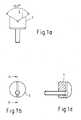
- Figure 1 a, b, c shows a support plate 1 according to the prior art, here for receiving round cutting plates.
- the support plate 1 is here provided with a 120 degree prism 2, in which a cutting plate, not shown here is used (see EP 0 350 938 A1 ).
- the invention has for its object to provide a cutting tool according to the preamble of claim 1, wherein the attachment of the cutting plate on the cutting tool is substantially improved.
- the cutting plate on its facing the support plate underside a groove into which a feather key positively engages, which is either integrally formed with the support plate or fixed in or on this.
- the facing the cutting top of the support plate advantageously has a slot into which the key is used form-fitting as an independent component.
- the key consists of a ceramic.
- the cutting plate on the underside facing the support plate on a raised key which engages positively in a corresponding groove on the cutting plate facing the top of the support plate.
- the support plate is fastened by a screw on the clamp holder, by tightening the screw, the support plate is pulled into its insert seat in the recess.
- the support plate has on its underside facing the clamping holder a web which engages in a corresponding groove in the clamping holder or vice versa.
- the groove is formed continuously on the underside of the cutting plate.
- the material of the cutting plate is preferably made of a ceramic. It can also be a cubic boron nitride CBN or a metal.
- the support plate is screwed from the front, the grooved wedge can also be designed in ceramic, which means less distortion in the holder due to the heat generated during machining.
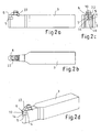
- FIGS. 2 a, b, c show a clamp holder 3 with a recess 4 for receiving a support plate 5.
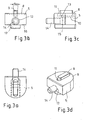
- the support plate 5 itself show the FIGS. 3 a, b, c, d .
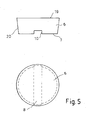
- the FIGS. 4 a, b, c show the associated key 9 and FIG. 5 shows an insert 6 according to the invention.
- the cutting plate 6 is preferably a circular cutting plate, but may also have other geometries, on its side facing the support plate 5 bottom 7 (see especially FIG. 5 ) has a groove 10.
- the cutting plate 6 is made of a ceramic, but it can also be made of another material, such. B. metal.
- the cutting plate 6 is attached via a clamping claw 22 on the clamp holder 3.
- a support plate 5 is inserted, which in detail in FIG. 3 is shown.
- the support plate 5 has on its facing the cutting plate 6 top 8 a feather key 9, which is adapted with its width 9a to the groove 10 in the cutting plate 6.
- the feather key 9 is a separate component (see FIG. 4 ) and consists of a ceramic.
- a slot 11 is introduced on the upper side 8 of the support plate 5, in which the feather key 9 is inserted.
- the support plate 5 is bolted to the clamp holder 3.
- it has a bore 12 with a conical diameter reduction 13.
- a screw 14 can be used, which is seated with its head 15 on the conical diameter reduction 13 and engages with its thread in a matching mating thread in the clamp holder 3. By tightening the screw 14, the support plate 5 is pulled into its insert seat in the recess 4 of the clamping holder 3.
- the support plate 5 On its side facing the clamp holder 3 bottom 16, the support plate 5 has a web 17 which engages in a corresponding groove 18 in the clamp holder 3. This groove 18 (see FIG. 2c) serves to guide the support plate 5 on the clamp holder. 3
- the support plate 6 (see FIG. 5 ) is executed in this case as a circular cutting plate and is provided with a flat top 19.
- the groove 10 on its underside 7 is preferably formed continuously. Excellent is suitable as a material for this insert 6, a cubic boron nitride CBN. But it can also consist of a different material.
- the flank 20 of the cutting plate 6 is preferably conical, wherein the diameter of the cutting plate 6 decreases in the direction of the groove 10.
- the feather key 9 (see FIG. 4 ) is provided at its edges in each case with a chamfer 21 and is preferably made of a ceramic.
Landscapes
- Engineering & Computer Science (AREA)
- Mechanical Engineering (AREA)
- Cutting Tools, Boring Holders, And Turrets (AREA)
- Polishing Bodies And Polishing Tools (AREA)
- Details Of Rigid Or Semi-Rigid Containers (AREA)
- Drilling Tools (AREA)
- Dowels (AREA)
- Battery Mounting, Suspending (AREA)
- Auxiliary Devices For And Details Of Packaging Control (AREA)
Description
- Die Erfindung betrifft ein Schneidwerkzeug zur spanabhebenden Bearbeitung nach dem Oberbegriff des Anspruchs 1 wie dies beispielweise aus der
US 4 077 735 bekannt ist. -
Figur 1 a, b, c zeigt eine Stützplatte 1 nach dem Stand der Technik, hier zur Aufnahme von Rundschneidplatten. Die Stützplatte 1 ist hierbei mit einem 120 Grad Prisma 2 versehen, in welches eine hier nicht gezeigte Schneidplatte eingesetzt wird (siehe hierzuEP 0 350 938 A1 ). - Bei einer Schneidplattendicke von z. B. 4,76 mm ist die Schneidplatte am Auslauf des Prismas sehr dünn. Außerdem führen die Toleranzen der Schneidplatte zur Stützplatte zu ungenauer Positionierung. Dadurch ist kein ausreichender Plattensitz gewährleistet. Dieses gilt im Augenblick besonders für CBN Schneidplatten, d. h. Schneidplatten aus kubischen Bornitrid.
- Der Erfindung liegt die Aufgabe zugrunde, ein Schneidwerkzeug nach dem Oberbegriff des Anspruchs 1 anzugeben, bei dem die Befestigung der Schneidplatte auf dem Schneidwerkzeug wesentlich verbessert ist.
- Erfindungsgemäß wird diese Aufgabe durch die Merkmale des Anspruchs 1 gelöst.
- Dadurch, dass die Schneidplatte über eine formschlüssige Nut-Feder-Verbindung auf der Stützplatte aufsitzt, ist die Befestigung wesentlich verbessert.
- In erfindungsgemäßer Ausgestaltung weist die Schneidplatte auf ihrer zur Stützplatte gewandten Unterseite eine Nut auf, in die eine Passfeder formschlüssig eingreift, die entweder einstückig mit der Stützplatte ausgebildet ist oder in oder an dieser befestigt ist.
- Die zur Schneidplatte gewandte Oberseite der Stützplatte weist vorteilhaft einen Schlitz auf, in den die Passfeder als eigenständiges Bauteil formschlüssig eingesetzt ist.
- Bevorzugt besteht die Passfeder aus einer Keramik.
- In einer Ausgestaltung weist die Schneidplatte auf der zur Stützplatte gewandten Unterseite eine erhabene Passfeder auf, die in eine entsprechende Nut auf der zur Schneidplatte gewandten Oberseite der Stützplatte formschlüssig eingreift.
- Die Stützplatte ist über eine Schraube auf dem Klemmhalter befestigt, wobei durch Festdrehen der Schraube die Stützplatte in ihren Plattensitz in der Ausnehmung gezogen wird.
- In einer Ausgestaltung weist die Stützplatte auf ihrer zum Klemmhalter gewandten Unterseite einen Steg auf, der in eine entsprechende Nut im Klemmhalter eingreift oder umgekehrt.
- Vorteilhaft ist die Nut auf der Unterseite der Schneidplatte durchgängig ausgebildet. Das Material der Schneidplatte besteht bevorzugt aus einer Keramik. Es kann auch ein kubisches Bornitrid CBN oder ein Metall sein.
- Durch das erfindungsgemäße Einbringen einer formschlüssigen Nut-Feder Verbindung zwischen Schneidplatte und Stützplatte ist, aufgrund der plangeschliffenen Schneidplatte und der Führung in der Feder, ein besserer Plattensitz gewährleistet. Dadurch dass die Stützplatte von vorne geschraubt wird, kann der Nutenkeil auch in Keramik ausgelegt werden, was aufgrund der entstehenden Wärme bei der Zerspanung weniger Verzug im Halter bedeutet.
- Nachfolgend wird die Erfindung anhand von Figuren näher erläutert.
- Die
Figuren 2 a, b, c, zeigen einen Klemmhalter 3 mit einer Ausnehmung 4 zur Aufnahme einer Stützplatte 5. Die Stützplatte 5 selbst zeigen dieFiguren 3 a, b, c, d . DieFiguren 4 a, b, c zeigen die zugehörige Passfeder 9 undFigur 5 zeigt eine erfindungsgemäße Schneidplatte 6. - Die Schneidplatte 6 ist bevorzugt eine Rundschneidplatte, kann aber auch andere Geometrien aufweisen, die an ihrer zur Stützplatte 5 gewandten Unterseite 7 (siehe besonders
Figur 5 ) eine Nut 10 aufweist. Bevorzugt besteht die Schneidplatte 6 aus einer Keramik, sie kann jedoch auch aus einem anderen Material, wie z. B. Metall bestehen. Die Schneidplatte 6 ist über eine Spannpratze 22 auf dem Klemmhalter 3 befestigt. - In einer Ausnehmung 4 des Klemmhalters 3 ist eine Stützplatte 5 eingesetzt, die im Einzelnen in
Figur 3 gezeigt ist. Die Stützplatte 5 weist an ihrer zur Schneidplatte 6 gewandten Oberseite 8 eine Passfeder 9 auf, die mit ihrer Breite 9a an die Nut 10 in der Schneidplatte 6 angepasst ist. - Bevorzugt ist die Passfeder 9 ein separates Bauteil (siehe
Figur 4 ) und besteht aus einer Keramik. - In dieser bevorzugten Ausführungsform ist auf der Oberseite 8 der Stützplatte 5 ein Schlitz 11 eingebracht, in den die Passfeder 9 eingesetzt ist.
- Die Stützplatte 5 ist auf dem Klemmhalter 3 verschraubt. Hierzu weist sie eine Bohrung 12 mit einer konischen Durchmesserverringerung 13 auf. In diese Bohrung 12 lässt sich eine Schraube 14 einsetzen, die mit ihrem Kopf 15 an der konischen Durchmesserverringerung 13 aufsitzt und mit ihrem Gewinde in ein passendes Gegengewinde im Klemmhalter 3 eingreift. Durch Festdrehen der Schraube 14 wird die Stützplatte 5 in ihren Plattensitz in der Ausnehmung 4 des Klemmhalters 3 gezogen.
- An ihrer zum Klemmhalter 3 gewandten Unterseite 16 weist die Stützplatte 5 einen Steg 17 auf, der in eine entsprechende Nut 18 im Klemmhalter 3 eingreift. Diese Nut 18 (siehe
Figur 2 c) dient zur Führung der Stützplatte 5 auf dem Klemmhalter 3. - Die Stützplatte 6 (siehe
Figur 5 ) ist in hier als Rundschneidplatte ausgeführt und ist mit einer planen Oberseite 19 versehen. Die Nut 10 an ihrer Unterseite 7 ist bevorzugt durchgängig ausgebildet. Vorzüglich eignet sich als Material für diese Schneidplatte 6 ein kubisches Bornitrid CBN. Sie kann aber auch aus einem anderen Material bestehen. Die Flanke 20 der Schneidplatte 6 ist bevorzugt konisch ausgebildet, wobei der Durchmesser der Schneidplatte 6 in Richtung zur Nut 10 abnimmt. - Die Passfeder 9 (siehe
Figur 4 ) ist an ihren Kanten jeweils mit einer Fase 21 versehen und besteht bevorzugt aus einer Keramik.
Claims (7)
- Schneidwerkzeug zur spanabhebenden Bearbeitung, im Wesentlichen bestehend aus einem Klemmhalter (3) mit einer Ausnehmung (4) zur Aufnahme einer Stützplatte (5) und mit einer Schneidplatte (6), die auf der Stützplatte (5) über eine Spannpratze (22) befestigt ist, wobei die Schneidplatte (6) über eine erste formschlüssige Nut-Feder-Verbindung auf der Stützplatte aufsitzt, die Stützplatte (5) über eine Schraube (14) auf dem Klemmhalter befestigt ist und durch Festdrehen der Schraube (14) die Stützplatte (5) in ihren Plattensitz in der Ausnehmung gezogen wird, dadurch gekennzeichnet, dass die Stützplatte (5) über eine zweite formschlüssige Nut-Feder-Verbindung auf dem Klemmhalter (3) aufsitzt und von vorne mit der Schraube (14) geschraubt wird und die zweite Nut-Feder-Verbindung parallel zur Achse der Schraube (14) angeordnet ist und die erste Nut-Feder-Verbindung der Schneidplatte (6) mit der Stützplatte (5) ebenfalls parallel zur Achse der Schraube (14) angeordnet ist.
- Schneidwerkzeug nach Anspruch 1, dadurch gekennzeichnet, dass die Schneidplatte (6) auf ihrer zur Stützplatte (5) gewandten Unterseite (7) eine Nut (10) aufweist, in die eine Passfeder (9) formschlüssig eingreift, die entweder einstückig mit der Stützplatte (5) ausgebildet ist oder in oder an dieser befestigt ist.
- Schneidwerkzeug nach Anspruch 2, dadurch gekennzeichnet, dass die zur Schneidplatte (6) gewandte Oberseite (8) der Stützplatte (5) einen Schlitz (11) aufweist, in den die Passfeder (9) als eigenständiges Bauteil formschlüssig eingesetzt ist.
- Schneidwerkzeug nach Anspruch 2 oder 3, dadurch gekennzeichnet, dass die Passfeder (9) aus einer Keramik besteht.
- Schneidwerkzeug nach Anspruch 1, dadurch gekennzeichnet, dass die Schneidplatte (6) auf der zur Stützplatte (5) gewandten Unterseite (7) eine erhabene Passfeder (9) aufweist, die in eine entsprechende Nut (11) auf der zur Schneidplatte (6) gewandten Oberseite (8) der Stützplatte (5) formschlüssig eingreift.
- Schneidwerkzeug nach einem der Ansprüche 1 bis 5, dadurch gekennzeichnet, dass die Stützplatte (5) auf ihrer zum Klemmhalter (3) gewandten Unterseite (16) einen Steg (17) aufweist, der in eine entsprechende Nut (18) im Klemmhalter (3) eingreift oder umgekehrt.
- Schneidwerkzeug nach einem der Ansprüche 1 bis 6, dadurch gekennzeichnet, dass das Material der Schneidplatte (6) eine Keramik oder ein kubisches Bornitrid ist.
Applications Claiming Priority (3)
| Application Number | Priority Date | Filing Date | Title |
|---|---|---|---|
| DE102006001309 | 2006-01-09 | ||
| DE102006052701A DE102006052701A1 (de) | 2006-01-09 | 2006-11-07 | Formschlüssig befestigte Schneidplatte auf einer Stützplatte |
| PCT/EP2007/050110 WO2007080151A1 (de) | 2006-01-09 | 2007-01-05 | Formschlüssig befestigte schneidplatte auf einer stützplatte |
Publications (2)
| Publication Number | Publication Date |
|---|---|
| EP1979118A1 EP1979118A1 (de) | 2008-10-15 |
| EP1979118B1 true EP1979118B1 (de) | 2010-10-27 |
Family
ID=37882244
Family Applications (1)
| Application Number | Title | Priority Date | Filing Date |
|---|---|---|---|
| EP07703668A Not-in-force EP1979118B1 (de) | 2006-01-09 | 2007-01-05 | Formschlüssig befestigte schneidplatte auf einer stützplatte |
Country Status (11)
| Country | Link |
|---|---|
| US (1) | US20090304466A1 (de) |
| EP (1) | EP1979118B1 (de) |
| JP (1) | JP2009522127A (de) |
| KR (1) | KR20080087816A (de) |
| AT (1) | ATE485910T1 (de) |
| BR (1) | BRPI0706454A2 (de) |
| CA (1) | CA2636403A1 (de) |
| DE (2) | DE102006052701A1 (de) |
| IL (1) | IL192724A0 (de) |
| MX (1) | MX2008008641A (de) |
| WO (1) | WO2007080151A1 (de) |
Families Citing this family (2)
| Publication number | Priority date | Publication date | Assignee | Title |
|---|---|---|---|---|
| DE102012219490A1 (de) | 2011-10-26 | 2013-05-02 | Ceramtec Gmbh | Werkzeugsystem |
| HUE051280T2 (hu) | 2017-03-22 | 2021-03-01 | Ceram Gmbh | Szerszámrendszer |
Citations (2)
| Publication number | Priority date | Publication date | Assignee | Title |
|---|---|---|---|---|
| EP0094537A1 (de) * | 1982-05-19 | 1983-11-23 | Zinner GmbH | Ein- und Mehrfachstechwerkzeug |
| EP0568515A1 (de) * | 1992-04-28 | 1993-11-03 | Sandvik Aktiebolag | Unterlegplatte für Schneidwerkzeug |
Family Cites Families (9)
| Publication number | Priority date | Publication date | Assignee | Title |
|---|---|---|---|---|
| LU35523A1 (de) * | 1956-10-27 | 1957-12-21 | ||
| US3303553A (en) * | 1964-08-24 | 1967-02-14 | Viking Tool Company | Cutting tool assembly |
| US4077735A (en) * | 1976-10-14 | 1978-03-07 | General Electric Company | Cutting tool and insert assembly |
| US4189264A (en) * | 1978-09-15 | 1980-02-19 | Fansteel Inc. | Cutting insert and chip control assembly |
| US4315706A (en) * | 1980-04-07 | 1982-02-16 | General Electric Company | Holder assembly for an indexable insert for use in a cutting tool |
| SE509363C2 (sv) * | 1995-09-25 | 1999-01-18 | Sandvik Ab | Fastspänningsanordning fjör skärplattor samt skärplatta avsedd för dylik anordning |
| SE511934C2 (sv) * | 1997-09-24 | 1999-12-20 | Sandvik Ab | Verktyg för spånavskiljande bearbetning |
| JP2000052111A (ja) * | 1998-08-03 | 2000-02-22 | Mitsubishi Materials Corp | 切削工具のスローアウェイチップ保持機構 |
| DE10113633B4 (de) * | 2001-03-21 | 2006-04-13 | Jakob Lach Gmbh & Co. Kg | Profil-Drehwerkzeug |
-
2006
- 2006-11-07 DE DE102006052701A patent/DE102006052701A1/de not_active Withdrawn
-
2007
- 2007-01-05 BR BRPI0706454-3A patent/BRPI0706454A2/pt not_active IP Right Cessation
- 2007-01-05 EP EP07703668A patent/EP1979118B1/de not_active Not-in-force
- 2007-01-05 AT AT07703668T patent/ATE485910T1/de active
- 2007-01-05 KR KR1020087016911A patent/KR20080087816A/ko not_active Withdrawn
- 2007-01-05 US US12/159,068 patent/US20090304466A1/en not_active Abandoned
- 2007-01-05 CA CA002636403A patent/CA2636403A1/en not_active Abandoned
- 2007-01-05 DE DE502007005461T patent/DE502007005461D1/de active Active
- 2007-01-05 JP JP2008549865A patent/JP2009522127A/ja active Pending
- 2007-01-05 WO PCT/EP2007/050110 patent/WO2007080151A1/de not_active Ceased
- 2007-01-05 MX MX2008008641A patent/MX2008008641A/es not_active Application Discontinuation
-
2008
- 2008-07-09 IL IL192724A patent/IL192724A0/en unknown
Patent Citations (2)
| Publication number | Priority date | Publication date | Assignee | Title |
|---|---|---|---|---|
| EP0094537A1 (de) * | 1982-05-19 | 1983-11-23 | Zinner GmbH | Ein- und Mehrfachstechwerkzeug |
| EP0568515A1 (de) * | 1992-04-28 | 1993-11-03 | Sandvik Aktiebolag | Unterlegplatte für Schneidwerkzeug |
Also Published As
| Publication number | Publication date |
|---|---|
| JP2009522127A (ja) | 2009-06-11 |
| DE102006052701A1 (de) | 2007-07-26 |
| US20090304466A1 (en) | 2009-12-10 |
| EP1979118A1 (de) | 2008-10-15 |
| BRPI0706454A2 (pt) | 2011-03-29 |
| KR20080087816A (ko) | 2008-10-01 |
| ATE485910T1 (de) | 2010-11-15 |
| CA2636403A1 (en) | 2007-07-19 |
| DE502007005461D1 (de) | 2010-12-09 |
| WO2007080151A1 (de) | 2007-07-19 |
| MX2008008641A (es) | 2008-11-06 |
| IL192724A0 (en) | 2009-02-11 |
Similar Documents
| Publication | Publication Date | Title |
|---|---|---|
| EP2366477B1 (de) | Ausdrehkopf | |
| DE102010004526B4 (de) | Zerspanungswerkzeug | |
| WO2014001447A1 (de) | Werkzeug für die spanende bearbeitung | |
| DE2326748A1 (de) | Abspanendes werkzeug mit auswechselbarem schneideinsatz | |
| EP2724817A1 (de) | Spannbacke oder Spannelement | |
| DE60301887T2 (de) | Schneidwerkzeugkopf für ein metallbearbeitungswerkzeug | |
| DE2402971B2 (de) | Halter eines schneidwerkzeuges der spanabhebenden bearbeitung | |
| DE102013101944A1 (de) | Schneidrad zur Bildung einer Fase | |
| EP1896209B1 (de) | Ventilsitz- und ventilführungsbearbeitungswerkzeug | |
| DE3529620A1 (de) | Schneidplatte | |
| DE102007011395A1 (de) | Scheibenfräserwerkzeug und Schneidelement | |
| DE102022130057A1 (de) | Verbindungsvorrichtung, Montagevorrichtung und System jeweils zum Verbinden eines ersten Bauteils und eines zweiten Bauteils | |
| WO2007080151A1 (de) | Formschlüssig befestigte schneidplatte auf einer stützplatte | |
| DE102005019945B4 (de) | Trägerwerkzeug für eine Schneidplatte mit zwei Schneiden und Schneidplatte mit zwei Schneiden | |
| DE3211460A1 (de) | Zerspanungswerkzeug | |
| EP3292931B1 (de) | Werkzeug, insbesondere für die spanabhebende werkstückbearbeitung | |
| EP2101944B1 (de) | Spanabhebendes werkzeug | |
| DE2312077C3 (de) | Schneidwerkzeug mit mindestens einem in einer Aussparung des Halters auf einer Unterlageplatte angeordneten Schneideinsatz | |
| DE202009010943U1 (de) | Werkzeug zur spanabhebenden Bearbeitung von Werkstücken | |
| EP1543927B1 (de) | Messerleiste | |
| DE8513350U1 (de) | Drehmeißel zum spanenden Bearbeiten von Werkstücken | |
| DE102019102167B3 (de) | Spannbacke zum Spannen eines Werkstücks | |
| DE102006055255A1 (de) | Trägerwerkzeug und Schneidplatte zum Einstechdrehen | |
| DE2544877A1 (de) | Werkzeughalter | |
| EP3412246B1 (de) | Halter für abutmentrohling für zahn-implantate |
Legal Events
| Date | Code | Title | Description |
|---|---|---|---|
| PUAI | Public reference made under article 153(3) epc to a published international application that has entered the european phase |
Free format text: ORIGINAL CODE: 0009012 |
|
| 17P | Request for examination filed |
Effective date: 20080811 |
|
| AK | Designated contracting states |
Kind code of ref document: A1 Designated state(s): AT BE BG CH CY CZ DE DK EE ES FI FR GB GR HU IE IS IT LI LT LU LV MC NL PL PT RO SE SI SK TR |
|
| 17Q | First examination report despatched |
Effective date: 20090213 |
|
| GRAP | Despatch of communication of intention to grant a patent |
Free format text: ORIGINAL CODE: EPIDOSNIGR1 |
|
| GRAS | Grant fee paid |
Free format text: ORIGINAL CODE: EPIDOSNIGR3 |
|
| GRAA | (expected) grant |
Free format text: ORIGINAL CODE: 0009210 |
|
| AK | Designated contracting states |
Kind code of ref document: B1 Designated state(s): AT BE BG CH CY CZ DE DK EE ES FI FR GB GR HU IE IS IT LI LT LU LV MC NL PL PT RO SE SI SK TR |
|
| REG | Reference to a national code |
Ref country code: GB Ref legal event code: FG4D Free format text: NOT ENGLISH |
|
| REG | Reference to a national code |
Ref country code: CH Ref legal event code: EP |
|
| REG | Reference to a national code |
Ref country code: IE Ref legal event code: FG4D Free format text: LANGUAGE OF EP DOCUMENT: GERMAN |
|
| RAP2 | Party data changed (patent owner data changed or rights of a patent transferred) |
Owner name: CERAMTEC GMBH |
|
| REF | Corresponds to: |
Ref document number: 502007005461 Country of ref document: DE Date of ref document: 20101209 Kind code of ref document: P |
|
| REG | Reference to a national code |
Ref country code: NL Ref legal event code: VDEP Effective date: 20101027 |
|
| LTIE | Lt: invalidation of european patent or patent extension |
Effective date: 20101027 |
|
| PG25 | Lapsed in a contracting state [announced via postgrant information from national office to epo] |
Ref country code: LT Free format text: LAPSE BECAUSE OF FAILURE TO SUBMIT A TRANSLATION OF THE DESCRIPTION OR TO PAY THE FEE WITHIN THE PRESCRIBED TIME-LIMIT Effective date: 20101027 |
|
| REG | Reference to a national code |
Ref country code: IE Ref legal event code: FD4D |
|
| PG25 | Lapsed in a contracting state [announced via postgrant information from national office to epo] |
Ref country code: BG Free format text: LAPSE BECAUSE OF FAILURE TO SUBMIT A TRANSLATION OF THE DESCRIPTION OR TO PAY THE FEE WITHIN THE PRESCRIBED TIME-LIMIT Effective date: 20110127 Ref country code: PT Free format text: LAPSE BECAUSE OF FAILURE TO SUBMIT A TRANSLATION OF THE DESCRIPTION OR TO PAY THE FEE WITHIN THE PRESCRIBED TIME-LIMIT Effective date: 20110228 Ref country code: FI Free format text: LAPSE BECAUSE OF FAILURE TO SUBMIT A TRANSLATION OF THE DESCRIPTION OR TO PAY THE FEE WITHIN THE PRESCRIBED TIME-LIMIT Effective date: 20101027 Ref country code: NL Free format text: LAPSE BECAUSE OF FAILURE TO SUBMIT A TRANSLATION OF THE DESCRIPTION OR TO PAY THE FEE WITHIN THE PRESCRIBED TIME-LIMIT Effective date: 20101027 Ref country code: IS Free format text: LAPSE BECAUSE OF FAILURE TO SUBMIT A TRANSLATION OF THE DESCRIPTION OR TO PAY THE FEE WITHIN THE PRESCRIBED TIME-LIMIT Effective date: 20110227 Ref country code: SE Free format text: LAPSE BECAUSE OF FAILURE TO SUBMIT A TRANSLATION OF THE DESCRIPTION OR TO PAY THE FEE WITHIN THE PRESCRIBED TIME-LIMIT Effective date: 20101027 Ref country code: SI Free format text: LAPSE BECAUSE OF FAILURE TO SUBMIT A TRANSLATION OF THE DESCRIPTION OR TO PAY THE FEE WITHIN THE PRESCRIBED TIME-LIMIT Effective date: 20101027 Ref country code: LV Free format text: LAPSE BECAUSE OF FAILURE TO SUBMIT A TRANSLATION OF THE DESCRIPTION OR TO PAY THE FEE WITHIN THE PRESCRIBED TIME-LIMIT Effective date: 20101027 |
|
| PG25 | Lapsed in a contracting state [announced via postgrant information from national office to epo] |
Ref country code: GR Free format text: LAPSE BECAUSE OF FAILURE TO SUBMIT A TRANSLATION OF THE DESCRIPTION OR TO PAY THE FEE WITHIN THE PRESCRIBED TIME-LIMIT Effective date: 20110128 |
|
| PG25 | Lapsed in a contracting state [announced via postgrant information from national office to epo] |
Ref country code: CZ Free format text: LAPSE BECAUSE OF FAILURE TO SUBMIT A TRANSLATION OF THE DESCRIPTION OR TO PAY THE FEE WITHIN THE PRESCRIBED TIME-LIMIT Effective date: 20101027 Ref country code: IE Free format text: LAPSE BECAUSE OF FAILURE TO SUBMIT A TRANSLATION OF THE DESCRIPTION OR TO PAY THE FEE WITHIN THE PRESCRIBED TIME-LIMIT Effective date: 20101027 Ref country code: ES Free format text: LAPSE BECAUSE OF FAILURE TO SUBMIT A TRANSLATION OF THE DESCRIPTION OR TO PAY THE FEE WITHIN THE PRESCRIBED TIME-LIMIT Effective date: 20110207 Ref country code: EE Free format text: LAPSE BECAUSE OF FAILURE TO SUBMIT A TRANSLATION OF THE DESCRIPTION OR TO PAY THE FEE WITHIN THE PRESCRIBED TIME-LIMIT Effective date: 20101027 |
|
| BERE | Be: lapsed |
Owner name: CERAMTEC A.G. Effective date: 20110131 |
|
| PG25 | Lapsed in a contracting state [announced via postgrant information from national office to epo] |
Ref country code: RO Free format text: LAPSE BECAUSE OF FAILURE TO SUBMIT A TRANSLATION OF THE DESCRIPTION OR TO PAY THE FEE WITHIN THE PRESCRIBED TIME-LIMIT Effective date: 20101027 Ref country code: PL Free format text: LAPSE BECAUSE OF FAILURE TO SUBMIT A TRANSLATION OF THE DESCRIPTION OR TO PAY THE FEE WITHIN THE PRESCRIBED TIME-LIMIT Effective date: 20101027 Ref country code: DK Free format text: LAPSE BECAUSE OF FAILURE TO SUBMIT A TRANSLATION OF THE DESCRIPTION OR TO PAY THE FEE WITHIN THE PRESCRIBED TIME-LIMIT Effective date: 20101027 Ref country code: MC Free format text: LAPSE BECAUSE OF NON-PAYMENT OF DUE FEES Effective date: 20110131 Ref country code: SK Free format text: LAPSE BECAUSE OF FAILURE TO SUBMIT A TRANSLATION OF THE DESCRIPTION OR TO PAY THE FEE WITHIN THE PRESCRIBED TIME-LIMIT Effective date: 20101027 |
|
| REG | Reference to a national code |
Ref country code: CH Ref legal event code: PL |
|
| PLBE | No opposition filed within time limit |
Free format text: ORIGINAL CODE: 0009261 |
|
| STAA | Information on the status of an ep patent application or granted ep patent |
Free format text: STATUS: NO OPPOSITION FILED WITHIN TIME LIMIT |
|
| GBPC | Gb: european patent ceased through non-payment of renewal fee |
Effective date: 20110127 |
|
| 26N | No opposition filed |
Effective date: 20110728 |
|
| REG | Reference to a national code |
Ref country code: FR Ref legal event code: ST Effective date: 20110930 |
|
| PG25 | Lapsed in a contracting state [announced via postgrant information from national office to epo] |
Ref country code: LI Free format text: LAPSE BECAUSE OF NON-PAYMENT OF DUE FEES Effective date: 20110131 Ref country code: CH Free format text: LAPSE BECAUSE OF NON-PAYMENT OF DUE FEES Effective date: 20110131 Ref country code: FR Free format text: LAPSE BECAUSE OF NON-PAYMENT OF DUE FEES Effective date: 20110131 |
|
| REG | Reference to a national code |
Ref country code: DE Ref legal event code: R097 Ref document number: 502007005461 Country of ref document: DE Effective date: 20110728 |
|
| PG25 | Lapsed in a contracting state [announced via postgrant information from national office to epo] |
Ref country code: GB Free format text: LAPSE BECAUSE OF NON-PAYMENT OF DUE FEES Effective date: 20110127 Ref country code: BE Free format text: LAPSE BECAUSE OF NON-PAYMENT OF DUE FEES Effective date: 20110131 |
|
| REG | Reference to a national code |
Ref country code: DE Ref legal event code: R119 Ref document number: 502007005461 Country of ref document: DE Effective date: 20110802 |
|
| PG25 | Lapsed in a contracting state [announced via postgrant information from national office to epo] |
Ref country code: IT Free format text: LAPSE BECAUSE OF FAILURE TO SUBMIT A TRANSLATION OF THE DESCRIPTION OR TO PAY THE FEE WITHIN THE PRESCRIBED TIME-LIMIT Effective date: 20101027 |
|
| REG | Reference to a national code |
Ref country code: AT Ref legal event code: MM01 Ref document number: 485910 Country of ref document: AT Kind code of ref document: T Effective date: 20120105 |
|
| PG25 | Lapsed in a contracting state [announced via postgrant information from national office to epo] |
Ref country code: CY Free format text: LAPSE BECAUSE OF FAILURE TO SUBMIT A TRANSLATION OF THE DESCRIPTION OR TO PAY THE FEE WITHIN THE PRESCRIBED TIME-LIMIT Effective date: 20101027 Ref country code: LU Free format text: LAPSE BECAUSE OF NON-PAYMENT OF DUE FEES Effective date: 20110105 |
|
| PG25 | Lapsed in a contracting state [announced via postgrant information from national office to epo] |
Ref country code: AT Free format text: LAPSE BECAUSE OF NON-PAYMENT OF DUE FEES Effective date: 20120105 Ref country code: DE Free format text: LAPSE BECAUSE OF NON-PAYMENT OF DUE FEES Effective date: 20110802 |
|
| PG25 | Lapsed in a contracting state [announced via postgrant information from national office to epo] |
Ref country code: TR Free format text: LAPSE BECAUSE OF FAILURE TO SUBMIT A TRANSLATION OF THE DESCRIPTION OR TO PAY THE FEE WITHIN THE PRESCRIBED TIME-LIMIT Effective date: 20101027 |
|
| PG25 | Lapsed in a contracting state [announced via postgrant information from national office to epo] |
Ref country code: HU Free format text: LAPSE BECAUSE OF FAILURE TO SUBMIT A TRANSLATION OF THE DESCRIPTION OR TO PAY THE FEE WITHIN THE PRESCRIBED TIME-LIMIT Effective date: 20101027 |