EP1978787B1 - Interface pour appareils de fonctionnement de lampes à perte moindres en veille - Google Patents
Interface pour appareils de fonctionnement de lampes à perte moindres en veille Download PDFInfo
- Publication number
- EP1978787B1 EP1978787B1 EP08160677.4A EP08160677A EP1978787B1 EP 1978787 B1 EP1978787 B1 EP 1978787B1 EP 08160677 A EP08160677 A EP 08160677A EP 1978787 B1 EP1978787 B1 EP 1978787B1
- Authority
- EP
- European Patent Office
- Prior art keywords
- operating device
- lamp operating
- signals
- input
- interface
- Prior art date
- Legal status (The legal status is an assumption and is not a legal conclusion. Google has not performed a legal analysis and makes no representation as to the accuracy of the status listed.)
- Expired - Lifetime
Links
Images


Classifications
-
- H—ELECTRICITY
- H05—ELECTRIC TECHNIQUES NOT OTHERWISE PROVIDED FOR
- H05B—ELECTRIC HEATING; ELECTRIC LIGHT SOURCES NOT OTHERWISE PROVIDED FOR; CIRCUIT ARRANGEMENTS FOR ELECTRIC LIGHT SOURCES, IN GENERAL
- H05B47/00—Circuit arrangements for operating light sources in general, i.e. where the type of light source is not relevant
- H05B47/10—Controlling the light source
- H05B47/175—Controlling the light source by remote control
- H05B47/18—Controlling the light source by remote control via data-bus transmission
-
- H—ELECTRICITY
- H05—ELECTRIC TECHNIQUES NOT OTHERWISE PROVIDED FOR
- H05B—ELECTRIC HEATING; ELECTRIC LIGHT SOURCES NOT OTHERWISE PROVIDED FOR; CIRCUIT ARRANGEMENTS FOR ELECTRIC LIGHT SOURCES, IN GENERAL
- H05B47/00—Circuit arrangements for operating light sources in general, i.e. where the type of light source is not relevant
- H05B47/10—Controlling the light source
- H05B47/175—Controlling the light source by remote control
- H05B47/18—Controlling the light source by remote control via data-bus transmission
- H05B47/183—Controlling the light source by remote control via data-bus transmission using digital addressable lighting interface [DALI] communication protocols
Definitions
- the present invention relates generally to interfaces for lamp operating devices, such as electronic ballasts for gas discharge lamps.
- the invention further relates to lamp operating devices with such interfaces and to methods for controlling a lamp operating device by means of an interface.
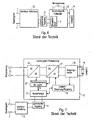
- Fig. 7 discloses an example of an interface to which signals from a push button / switch or digital signals from a bus can be selectively applied.
- a connected electronic ballast can be switched on or off, for example, by pressing a button.
- a setpoint for a brightness control can be achieved by a corresponding time duration of the push-button operation, since the connected evaluation logic of the interface converts the duration of the push-button operation into a setpoint signal for the electronic ballast (ECG).
- ECG electronic ballast
- a galvanic isolating element 4 such as an optocoupler provided.
- the digital signals supplied from a bus, for example, are transmitted via this galvanic isolating element 4 to the evaluation logic 3, which is thus located behind the galvanic isolating element 4 as seen from the bus.
- the evaluation logic 3 since the evaluation logic 3 must respond to incoming signals from the terminals of the interface 12 out immediately, there is the problem in the prior art that the lamp operating device can never be turned off completely, otherwise the evaluation logic would be switched off with.
- the evaluation logic must therefore be constantly supplied with mains voltage 15, which is reflected in corresponding standby losses (power that drops in standby mode).
- Standby losses are at odds with the enormous efforts that have been made lately in energy saving in the lamp industry.
- the WO 02/082618 A1 which shows a way to reduce standby losses in a DALI interface.
- a DALI processor is placed in a standby mode when no signals are transmitted on the connected DALI bus. Otherwise shows Fig. 3 of the WO 02/082618 A1 an example of the generally prevailing trend that the Ausretelogik seen from the DALI bus behind the galvanic separating element (insulation 310 in Fig. 3 ) must be arranged.
- the present invention now has the object to reduce the standby losses in an interface for a lamp operating device.
- the evaluation logic can be designed to transmit commands to the connected lamp operating device by means of the galvanic separating element, by means of which commands the lamp operating device can be separated from the mains voltage.
- the lamp operating device may be separable from the mains, for example, by means of a relay or an optocoupler-controlled triac.
- the evaluation logic can be designed to transmit control values to the connected lamp operating device by means of the same and / or by means of a separate galvanic separating element.
- control values for example, set values for a lamp brightness control
- a high-level signal is applied to the input-side terminals.
- this high-level signal is used to supply power to the evaluation logic. This would be obviously not possible if, as in the prior art, the Ausretelogik considered from the bus behind the galvanic separation element.
- an interface for a lamp operating device such as an ECG for a gas discharge lamp
- has an evaluation logic which is supplied by at least one input-side signal terminal of the interface with voltage.
- the invention also proposes a method for controlling a lamp operating device by means of an interface in which, for example, via a bus incoming signals are processed first, for example, by a Ausretelogik and converted into control signals for a lamp operating device before being transmitted by means of a galvanic separating element to the lamp operating device become.
- the conversion of the incoming signals is thus carried out before the transfer of the converted control commands via the Galvanic separator.
- control signals are applied to at least one input-side terminal 1, 2 of an interface circuit 12 according to the invention.
- connection 1, 2 for a bus line pair or a button / switch are shown, it should be emphasized that the present invention can also be applied to the interface for connecting a single signal line.
- the control signals can be, for example, digital signals (for example according to the DALI standard) or signals from a pushbutton / switch.
- an evaluation logic 3 is provided which converts the control signals supplied to the input-side terminals 1, 2 into control signals for a ballast electronics 13. These already converted control signals are transmitted from the evaluation logic 3 via a galvanic coupling, for example.
- the ballast electronics 13 is supplied in a known manner with mains voltage 15.
- the evaluation logic 3 is not supplied by means of the mains voltage supply 15 of the operating device (ballast here), but via the input-side terminals 1, 2 (for example, bus lines) with energy.
- the evaluation logic 3 is therefore independent of the power supply of the operating device with respect to their power supply.
- the evaluation logic 3 according to the invention is thus part of the interface 3 and no longer part of the operating device 13 as in the prior art.
- the evaluation logic 3 may, for example, be designed as an ASIC, microcontroller or DSP.
- the evaluation logic 3 is designed so that it is activated only when a change of the bus line to a high level signal by this voltage (wake-up), which Activation is sufficiently fast to ensure a secure detection of the first bit of the incoming digital signal.
- Fig. 2 shows in a detailed view, the interface circuit 12 with the evaluation logic 3 and the galvanic coupling 4.
- the ballast electronics 13, however, is in this Fig. 2 (as also explained in the following Fig. 3 ) not described further.
- a high-level signal is known to be present at the input-side terminals 1, 2 of the interface circuit 12 in the idle state, so that this high-level signal is used by means of a constant current source 5 (impressed current) and a diode 7 as the power supply 8 for the evaluation logic 3 can be.
- the evaluation logic 3 detects by means of a voltage divider to the input-side terminals 1, 2 applied control signals (in the DALI standard, for example, the edges of the digital signals), it implements according to a logic implemented in the evaluation logic 3 in control signals and supplies these output control signals 23 to the galvanic separation element 4, according to the embodiment of FIGS. 2 and 3 is designed as an optocoupler.
- a voltage divider to the input-side terminals 1, 2 applied control signals (in the DALI standard, for example, the edges of the digital signals)
- it implements according to a logic implemented in the evaluation logic 3 in control signals and supplies these output control signals 23 to the galvanic separation element 4, according to the embodiment of FIGS. 2 and 3 is designed as an optocoupler.
- other galvanic separating elements such as transformers, etc., are conceivable.
- the evaluation logic 3 of the input-side terminals 1, 2 of the interface 12 seen from arranged in front of the galvanic separation element 4 and thus is a genuine part of the interface 12. Furthermore, it should be noted that the evaluation logic 3 is not based on the mains voltage supply 15 of the operating device 13, but starting from the signal input terminals 1, 2 of the interface 12 is supplied with voltage.
- the galvanic coupling 4 may be formed as optocoupler-controlled triac, which can separate the entire ballast electronics 13 from the mains voltage 15 depending on the control by the evaluation logic 3. In this case fall in the ballast 13 in standby mode no more losses.
- ballast 13 eg the inverter
- Fig. 5 The embodiment according to Fig. 5 is opposite to that of Fig. 4 extended to the effect that the evaluation logic 3 (known in 4 and 5 not shown) not only controls a galvanic isolating element 4 for switching on / off the mains voltage 15 for the ballast electronics 13, but also about the same or as in Fig. 5 shown, a separate galvanic separating element 20 control values (for example, set values) for the lamp control 19 and other signals transmitted.
- the galvanic isolating element 20 (in the exemplary embodiment, an optocoupler) may be designed to be bidirectional and, in addition to the first transmission branch 22 for the manipulated variables, also have a feedback branch 21 for status information and / or error messages from the lamp control 19 or others To transfer components of the ballast electronics 13 via the branch 21 of the galvanic isolator 20 to the evaluation logic 3, so that these corresponding digital signals (24 in accordance with Fig. 3 ) can output at the terminals 1, 2 of the interface 12.
Landscapes
- Circuit Arrangement For Electric Light Sources In General (AREA)
- Selective Calling Equipment (AREA)
- Power Sources (AREA)
Claims (15)
- Interface pour un appareil d'alimentation de lampe (13), présentant- au moins un branchement d'entrée (1, 2) pour le branchement de lignes de bus ou pour la connexion avec un interrupteur ou commutateur, et- une logique d'évaluation (3) pour le traitement de signaux présents au branchement d'entrée (1, 2) et pour la production de signaux de sortie pour la commande de l'appareil d'alimentation de lampe (13), et- au moins un élément d'isolation galvanique (4) pour découpler galvaniquement le branchement d'entrée (1, 2) de l'appareil d'alimentation de lampe (13), caractérisée en ce que dans l'état de repos, dans lequel aucuns signaux ne sont transmis, un signal de niveau haut, qui alimente en énergie la logique d'évaluation (3), est présent aux branchements d'entrée.
- Interface selon la revendication 1,
caractérisée en ce que
dans l'état de repos, dans lequel aucuns signaux ne sont transmis, un signal de niveau bas est présent aux branchements d'entrée et la logique d'évaluation (3) est apte à être activée par un changement sur un signal de niveau haut. - Interface selon la revendication 1 ou 2, caractérisée en ce que la logique d'évaluation (3) est configurée pour éteindre au moins partiellement un appareil d'alimentation de lampe connecté (13).
- Interface selon la revendication 3,
caractérisée en ce que
l'appareil d'alimentation de lampe (13) est apte à être coupé du réseau au moyen d'un relais ou d'un triac commandé par optocoupleur. - Interface selon l'une des revendications précédentes, caractérisée en ce que la logique d'évaluation (3) est configurée pour transmettre, au moyen du même et/ou au moyen d'un élément d'isolation galvanique séparé (4), des valeurs de réglage à l'appareil d'alimentation de lampe connecté (13).
- Interface selon l'une des revendications précédentes, caractérisée en ce que l'élément d'isolation galvanique (4) est configuré pour transmettre de manière bidirectionnelle également des signaux d'un appareil d'alimentation de lampe connecté (13) aux branchements d'entrée et le cas échéant à un bus qui y est connecté.
- Interface selon l'une des revendications précédentes, dans laquelle le dispositif électronique d'évaluation est réalisée sous forme d'ASIC, microprocesseur ou DSP.
- Interface selon l'une des revendications précédentes, dans laquelle le dispositif électronique d'évaluation est spécifiée pour la norme DALI.
- Appareil d'alimentation de lampe, en particulier ballast pour tubes fluorescents, présentant une interface (12) selon l'une des revendications précédentes.
- Procédé de commande d'un appareil d'alimentation de lampe par l'intermédiaire d'une interface (12), présentant les étapes suivantes :- application de signaux de bus ou de signaux d'interrupteur /de commutateur à au moins un branchement d'entrée (1, 2) de l'interface (12),- traitement de signaux présents au branchement d'entrée et production de signaux de sortie pour la commande de l'appareil d'alimentation de lampe (13) au moyen d'un dispositif électronique d'évaluation, dans lequel dans l'état de repos, dans lequel aucuns signaux ne sont transmis, un signal de niveau haut, qui alimente en énergie la logique d'évaluation (3), est présent aux branchements d'entrée (1, 2), ou dans lequel dans l'état de repos, dans lequel aucuns signaux ne sont transmis, un signal de niveau bas est présent aux branchements d'entrée (1, 2) et la logique d'évaluation (3) est activée par un changement sur un signal de niveau haut.
- Procédé selon la revendication 10,
caractérisé en ce que,
au moyen d'un élément d'isolation galvanique (4), des signaux ou des instructions sont transmis à l'appareil d'alimentation de lampe connecté (13), par lequel celui-ci est isolé de la tension de réseau (15). - Procédé selon la revendication 11,
caractérisé en ce que
l'appareil d'alimentation de lampe (13) est coupé du réseau au moyen d'un relais ou d'un triac commandé par optocoupleur. - Procédé selon l'une des revendications 11 ou 12, caractérisé en ce que, au moyen de l'élément d'isolation galvanique (4), des valeurs de réglage sont transmises à l'appareil d'alimentation de lampe connecté (13).
- Procédé selon l'une des revendications 11 à 13, caractérisé en ce que des signaux sont transmis d'un appareil d'alimentation de lampe connecté (13) aux branchements d'entrée (1, 2) et le cas échéant à un bus qui y est connecté.
- Système, présentant
un bus et au moins un appareil d'alimentation de lampe selon la revendication 9.
Applications Claiming Priority (2)
| Application Number | Priority Date | Filing Date | Title |
|---|---|---|---|
| DE10329876.2A DE10329876B4 (de) | 2003-07-02 | 2003-07-02 | Schnittstelle für ein Lampenbetriebsgerät mit niedrigen Standby-Verlusten und Verfahren zur Ansteuerung eines Lampenbetriebsgeräts über eine derartige Schnittstelle |
| EP04740212A EP1639866B1 (fr) | 2003-07-02 | 2004-06-23 | Interface pour appareils d'exploitation de lampes a faibles pertes en mode d'attente |
Related Parent Applications (1)
| Application Number | Title | Priority Date | Filing Date |
|---|---|---|---|
| EP04740212A Division EP1639866B1 (fr) | 2003-07-02 | 2004-06-23 | Interface pour appareils d'exploitation de lampes a faibles pertes en mode d'attente |
Publications (2)
| Publication Number | Publication Date |
|---|---|
| EP1978787A1 EP1978787A1 (fr) | 2008-10-08 |
| EP1978787B1 true EP1978787B1 (fr) | 2014-08-27 |
Family
ID=33521271
Family Applications (2)
| Application Number | Title | Priority Date | Filing Date |
|---|---|---|---|
| EP04740212A Expired - Lifetime EP1639866B1 (fr) | 2003-07-02 | 2004-06-23 | Interface pour appareils d'exploitation de lampes a faibles pertes en mode d'attente |
| EP08160677.4A Expired - Lifetime EP1978787B1 (fr) | 2003-07-02 | 2004-06-23 | Interface pour appareils de fonctionnement de lampes à perte moindres en veille |
Family Applications Before (1)
| Application Number | Title | Priority Date | Filing Date |
|---|---|---|---|
| EP04740212A Expired - Lifetime EP1639866B1 (fr) | 2003-07-02 | 2004-06-23 | Interface pour appareils d'exploitation de lampes a faibles pertes en mode d'attente |
Country Status (10)
| Country | Link |
|---|---|
| US (1) | US7705546B2 (fr) |
| EP (2) | EP1639866B1 (fr) |
| CN (1) | CN1817067B (fr) |
| AT (1) | ATE406082T1 (fr) |
| AU (1) | AU2004300553B2 (fr) |
| BR (1) | BRPI0412227A (fr) |
| DE (2) | DE10329876B4 (fr) |
| RU (1) | RU2327307C2 (fr) |
| WO (1) | WO2005004552A1 (fr) |
| ZA (1) | ZA200510431B (fr) |
Families Citing this family (26)
| Publication number | Priority date | Publication date | Assignee | Title |
|---|---|---|---|---|
| WO2005072019A1 (fr) | 2004-01-21 | 2005-08-04 | Koninklijke Philips Electronics, N.V. | Ballast electronique avec interface de transformateur |
| US7369060B2 (en) | 2004-12-14 | 2008-05-06 | Lutron Electronics Co., Inc. | Distributed intelligence ballast system and extended lighting control protocol |
| CN101128079B (zh) * | 2006-08-16 | 2010-12-15 | 联昌电子企业股份有限公司 | 使用电性隔离控制的灯管驱动系统 |
| US8378529B2 (en) * | 2007-01-10 | 2013-02-19 | Osram Gesellschaft Mit Beschrankter Haftung | Switching actuator for controlling the energy supply to electric consumers |
| DE102007004810A1 (de) * | 2007-01-31 | 2008-08-07 | Tridonicatco Schweiz Ag | Schnittstelle für Tastersignale und Digitalsignale mit Schutzschaltung |
| DE102007009520B4 (de) * | 2007-02-27 | 2016-11-03 | Tridonic Gmbh & Co Kg | Schnittstelle für Digitalsignale und Netzspannungssignale, mit schaltbarer Konstantstromquelle |
| US7764479B2 (en) | 2007-04-18 | 2010-07-27 | Lutron Electronics Co., Inc. | Communication circuit for a digital electronic dimming ballast |
| DE102008017557A1 (de) * | 2008-03-25 | 2009-10-01 | Tridonicatco Gmbh & Co. Kg | Betriebsgerät für Leuchtmittel |
| EP2269423B1 (fr) * | 2008-03-31 | 2017-01-25 | Tridonic GmbH & Co KG | Procédé de commande d'un appareil pour faire fonctionner un moyen d'éclairage |
| WO2010043263A1 (fr) * | 2008-10-16 | 2010-04-22 | Osram Gesellschaft mit beschränkter Haftung | Dispositif d’interface pour un circuit de commande de lumière dali et procédé pour sa surveillance |
| DE102009009535A1 (de) * | 2009-02-18 | 2010-08-19 | Osram Gesellschaft mit beschränkter Haftung | Schaltung zur Ansteuerung eines Betriebsgeräts für eine Lichtanwendung, Betriebsgerät und Verfahren zum Betrieb der Schaltung |
| AT11444U1 (de) * | 2009-04-27 | 2010-10-15 | Tridonicatco Gmbh & Co Kg | Schnittstelle für eine beleuchtungsanlage |
| AT12594U1 (de) * | 2010-03-03 | 2012-08-15 | Tridonic Gmbh & Co Kg | Schnittstelle für ein betriebsgerät für leuchtmittel |
| DE102010036444B4 (de) | 2010-07-16 | 2012-03-22 | Vossloh-Schwabe Deutschland Gmbh | Verfahren und Vorrichtung zum Dimmen eines Leuchtmittels mithilfe eines Mikrocontrollers |
| DE102010040398A1 (de) * | 2010-09-08 | 2012-03-08 | Tridonic Gmbh & Co. Kg | Verbesserung der Energie-Effizienz einer mindestens eine Lichtquelle aufweisenden Beleuchtungsanlage sowie entsprechende Beleuchtungsanlage |
| DE102010052661B3 (de) * | 2010-11-26 | 2012-02-09 | Abb Ag | Kommunikationssystem zur Steuerung von elektrischen Lasten |
| EP2533612A1 (fr) | 2011-06-10 | 2012-12-12 | Exscitron GmbH | Dispositif d'alimentation pour DEL en mode de contrôle non activé |
| WO2012176097A1 (fr) * | 2011-06-21 | 2012-12-27 | Koninklijke Philips Electronics N.V. | Appareil d'éclairage et procédé utilisant de multiples schémas de gradation de l'intensité lumineuse |
| JP6320924B2 (ja) * | 2011-10-26 | 2018-05-09 | フィリップス ライティング ホールディング ビー ヴィ | 低電力待機シャットダウン回路 |
| RU2624452C2 (ru) | 2012-04-12 | 2017-07-04 | Филипс Лайтинг Холдинг Б.В. | Интерфейсная схема цифровой связи для проводной пары с индивидуально регулируемыми границами перехода |
| JP6382825B2 (ja) * | 2012-10-17 | 2018-08-29 | フィリップス ライティング ホールディング ビー ヴィ | デューティサイクル不均衡補償を備えた線対用のデジタル通信受信器インターフェース回路 |
| DE102013221848B4 (de) | 2013-10-28 | 2025-01-16 | Tridonic Gmbh & Co Kg | Schnittstelle mit verbessertem Sendezweig, entsprechendes Gebäudetechnik-Bussystem, Vorschaltgerät mit derartiger Schnittstelle sowie Leuchte mit derartigem Vorschaltgerät |
| EP2938165A1 (fr) * | 2014-04-23 | 2015-10-28 | RECOM Engineering GmbH & Co KG | Installation de commutation destinée au fonctionnement d'au moins un moyen d'éclairage |
| US9743474B2 (en) * | 2014-11-14 | 2017-08-22 | General Electric Company | Method and system for lighting interface messaging with reduced power consumption |
| AT16037U1 (de) | 2017-04-28 | 2018-11-15 | Tridonic Gmbh & Co Kg | Verfahren zur Steuerung eines Beleuchtungssystems |
| AT16321U1 (de) | 2018-03-08 | 2019-07-15 | Tridonic Gmbh & Co Kg | Verfahren zur Nutzung eines Beleuchtungssystems |
Family Cites Families (19)
| Publication number | Priority date | Publication date | Assignee | Title |
|---|---|---|---|---|
| US4656475A (en) * | 1979-10-30 | 1987-04-07 | General Electric Company | Method and apparatus for controlling distributed electrical loads |
| US4691341A (en) * | 1985-03-18 | 1987-09-01 | General Electric Company | Method of transferring digital information and street lighting control system |
| US5545955A (en) * | 1994-03-04 | 1996-08-13 | International Rectifier Corporation | MOS gate driver for ballast circuits |
| US6297724B1 (en) * | 1994-09-09 | 2001-10-02 | The Whitaker Corporation | Lighting control subsystem for use in system architecture for automated building |
| US6008590A (en) * | 1996-05-03 | 1999-12-28 | Philips Electronics North America Corporation | Integrated circuit inverter control having a multi-function pin |
| DE19757295B4 (de) * | 1997-03-04 | 2005-08-04 | Tridonicatco Gmbh & Co. Kg | Elektronisches Vorschaltgerät |
| ATE237919T1 (de) * | 1997-09-18 | 2003-05-15 | Ceag Sicherheitstechnik Gmbh | Beleuchtungssystem |
| DE19748007A1 (de) * | 1997-10-30 | 1999-05-12 | Tridonic Bauelemente | Schnittstelle für ein Lampenbetriebsgerät |
| WO1999060804A1 (fr) * | 1998-05-18 | 1999-11-25 | Leviton Manufacturing Co., Inc. | Systeme de commande electrique base sur un reseau a commande et detection reparties |
| US6081586A (en) * | 1998-11-16 | 2000-06-27 | Conexant Systems, Inc. | Modem having a programmable universal data access arrangement |
| GB0009962D0 (en) * | 2000-04-25 | 2000-06-14 | Hardwick Michael D | Energy saving |
| US6771029B2 (en) * | 2001-03-28 | 2004-08-03 | International Rectifier Corporation | Digital dimming fluorescent ballast |
| US6762570B1 (en) * | 2001-04-10 | 2004-07-13 | Microchip Technology Incorporated | Minimizing standby power in a digital addressable lighting interface |
| ATE310330T1 (de) * | 2001-04-06 | 2005-12-15 | Microchip Tech Inc | Einrichtung zur verminderung des energieverbrauchs im zustand der betriebsbereitschaft in dali |
| CN1701643A (zh) * | 2001-05-26 | 2005-11-23 | 尼克斯特克电力系统公司 | 遥控电子灯镇流器和其它装置 |
| DE10323689A1 (de) * | 2003-05-22 | 2004-12-09 | Patent-Treuhand-Gesellschaft für elektrische Glühlampen mbH | Steuerbare Lichtanlage mit zweitem Kommunikationsprotokoll und Geräte hierfür |
| DE10329683A1 (de) * | 2003-07-01 | 2005-02-03 | Tridonicatco Gmbh & Co. Kg | Digitale Schnittstelle mit Potentiometer |
| DE10345611A1 (de) * | 2003-09-29 | 2005-04-21 | Patent Treuhand Ges Fuer Elektrische Gluehlampen Mbh | Datenkonverter für eine Beleuchtungsanlage und Verfahren zum Betreiben einer Beleuchtungsanlage |
| US7619539B2 (en) * | 2004-02-13 | 2009-11-17 | Lutron Electronics Co., Inc. | Multiple-input electronic ballast with processor |
-
2003
- 2003-07-02 DE DE10329876.2A patent/DE10329876B4/de not_active Expired - Fee Related
-
2004
- 2004-06-23 EP EP04740212A patent/EP1639866B1/fr not_active Expired - Lifetime
- 2004-06-23 RU RU2006102952/28A patent/RU2327307C2/ru not_active IP Right Cessation
- 2004-06-23 EP EP08160677.4A patent/EP1978787B1/fr not_active Expired - Lifetime
- 2004-06-23 CN CN2004800186895A patent/CN1817067B/zh not_active Expired - Fee Related
- 2004-06-23 AU AU2004300553A patent/AU2004300553B2/en not_active Ceased
- 2004-06-23 WO PCT/EP2004/006793 patent/WO2005004552A1/fr not_active Ceased
- 2004-06-23 US US10/563,092 patent/US7705546B2/en not_active Expired - Fee Related
- 2004-06-23 ZA ZA200510431A patent/ZA200510431B/xx unknown
- 2004-06-23 BR BRPI0412227-5A patent/BRPI0412227A/pt not_active Application Discontinuation
- 2004-06-23 AT AT04740212T patent/ATE406082T1/de active
- 2004-06-23 DE DE502004007903T patent/DE502004007903D1/de not_active Expired - Lifetime
Also Published As
| Publication number | Publication date |
|---|---|
| DE10329876B4 (de) | 2016-06-02 |
| AU2004300553A1 (en) | 2005-01-13 |
| US7705546B2 (en) | 2010-04-27 |
| CN1817067A (zh) | 2006-08-09 |
| CN1817067B (zh) | 2010-09-22 |
| EP1639866A1 (fr) | 2006-03-29 |
| RU2006102952A (ru) | 2006-06-27 |
| ATE406082T1 (de) | 2008-09-15 |
| DE502004007903D1 (de) | 2008-10-02 |
| DE10329876A1 (de) | 2005-01-20 |
| WO2005004552A1 (fr) | 2005-01-13 |
| BRPI0412227A (pt) | 2006-08-22 |
| ZA200510431B (en) | 2007-03-28 |
| RU2327307C2 (ru) | 2008-06-20 |
| EP1639866B1 (fr) | 2008-08-20 |
| EP1978787A1 (fr) | 2008-10-08 |
| AU2004300553B2 (en) | 2010-11-18 |
| US20070138974A1 (en) | 2007-06-21 |
Similar Documents
| Publication | Publication Date | Title |
|---|---|---|
| EP1639866B1 (fr) | Interface pour appareils d'exploitation de lampes a faibles pertes en mode d'attente | |
| EP2225917B1 (fr) | Dispositif et procédé pour la commande d'appareils électriques | |
| WO2001052607A1 (fr) | Dispositif pour commander des moyens d'exploitation pour au moins un moyen d'eclairage electrique, et procede pour commander des moyens d'exploitation pour au moins un moyen d'eclairage electrique | |
| EP2812969A1 (fr) | Système d'alimentation électrique pourvu de sorties montables en parallèle | |
| EP2067270B1 (fr) | Circuit électrique | |
| AT407809B (de) | System zum steuern von mehreren an eine gemeinsame elektrische wechselspannungs- versorgungsleitung angeschlossenen verbrauchern | |
| EP2100480B1 (fr) | Actionneur de commutation pour commander l'alimentation en énergie d'utilisateurs électriques | |
| EP1659834B1 (fr) | Gradateur | |
| DE102017100967B4 (de) | Fernschaltvorrichtung und elektrische Fernsteuerungsvorrichtung | |
| EP1494507B1 (fr) | Interface numérique avec un potentiomètre | |
| DE102007013758B4 (de) | Busfähiges Betriebsgerät für Leuchtmittel mit temperaturkompensiertem Sendezweig, Verfahren zur Temperaturkompensation des Übertragungsverhaltens eines Optokopplers und Steuereinheit zur Durchführung des Verfahrens | |
| DE102004002027B4 (de) | Zentraler PFC mit DC-Ausgangskreisregelung | |
| EP1872629A1 (fr) | Protection de la branche emettrice d'un dispositif interface | |
| WO2008104253A1 (fr) | Interface pour signaux numériques et signaux de tension de secteur, avec source électrique constante commutable | |
| EP1525660B1 (fr) | Circuit de regulation de deux charges independantes fonctionnant a l'aide d'une tension alternative redressee | |
| DE102016104479A1 (de) | Gerät für eine Leuchte einer Notbeleuchtung und Leuchte mit einem solchem Gerät | |
| DE102007005995B4 (de) | Bedieneinheit für mindestens eine über einen DALI-Bus betriebene Beleuchtungskomponente | |
| EP4362609A1 (fr) | Circuit anti-effluves pour module à del | |
| DE102014111711B4 (de) | Steuerung der Leistungsaufnahme von elektrischen Verbrauchern im Außenbereich | |
| DE202021103225U1 (de) | Multifunktionsschalter einer Leuchtenanordnung, und Leuchtenanordnung | |
| DE102008031771A1 (de) | Elektrischer Schaltkreis eines Kraftfahrzeuges | |
| DE3030411A1 (de) | Vorrichtung zur einspeisung in eine notleute | |
| DE102008025949A1 (de) | Steuerung für elektrische Verbraucher | |
| DE202010000877U1 (de) | Universelles Elektroinstallationsgerät | |
| WO2014083187A1 (fr) | Gradateur comportant un relais en sortie |
Legal Events
| Date | Code | Title | Description |
|---|---|---|---|
| PUAI | Public reference made under article 153(3) epc to a published international application that has entered the european phase |
Free format text: ORIGINAL CODE: 0009012 |
|
| AC | Divisional application: reference to earlier application |
Ref document number: 1639866 Country of ref document: EP Kind code of ref document: P |
|
| AK | Designated contracting states |
Kind code of ref document: A1 Designated state(s): AT BE BG CH CY CZ DE DK EE ES FI FR GB GR HU IE IT LI LU MC NL PL PT RO SE SI SK TR |
|
| AX | Request for extension of the european patent |
Extension state: AL MK |
|
| 17P | Request for examination filed |
Effective date: 20090203 |
|
| AKX | Designation fees paid |
Designated state(s): AT BE BG CH CY CZ DE DK EE ES FI FR GB GR HU IE IT LI LU MC NL PL PT RO SE SI SK TR |
|
| RAP1 | Party data changed (applicant data changed or rights of an application transferred) |
Owner name: TRIDONIC GMBH & CO KG |
|
| GRAP | Despatch of communication of intention to grant a patent |
Free format text: ORIGINAL CODE: EPIDOSNIGR1 |
|
| INTG | Intention to grant announced |
Effective date: 20140108 |
|
| GRAS | Grant fee paid |
Free format text: ORIGINAL CODE: EPIDOSNIGR3 |
|
| GRAP | Despatch of communication of intention to grant a patent |
Free format text: ORIGINAL CODE: EPIDOSNIGR1 |
|
| INTG | Intention to grant announced |
Effective date: 20140620 |
|
| GRAA | (expected) grant |
Free format text: ORIGINAL CODE: 0009210 |
|
| AC | Divisional application: reference to earlier application |
Ref document number: 1639866 Country of ref document: EP Kind code of ref document: P |
|
| AK | Designated contracting states |
Kind code of ref document: B1 Designated state(s): AT BE BG CH CY CZ DE DK EE ES FI FR GB GR HU IE IT LI LU MC NL PL PT RO SE SI SK TR |
|
| REG | Reference to a national code |
Ref country code: GB Ref legal event code: FG4D Free format text: NOT ENGLISH |
|
| REG | Reference to a national code |
Ref country code: CH Ref legal event code: EP |
|
| REG | Reference to a national code |
Ref country code: AT Ref legal event code: REF Ref document number: 685047 Country of ref document: AT Kind code of ref document: T Effective date: 20140915 |
|
| REG | Reference to a national code |
Ref country code: IE Ref legal event code: FG4D Free format text: LANGUAGE OF EP DOCUMENT: GERMAN |
|
| REG | Reference to a national code |
Ref country code: DE Ref legal event code: R096 Ref document number: 502004014704 Country of ref document: DE Effective date: 20141009 |
|
| REG | Reference to a national code |
Ref country code: SE Ref legal event code: TRGR |
|
| REG | Reference to a national code |
Ref country code: NL Ref legal event code: VDEP Effective date: 20140827 |
|
| PG25 | Lapsed in a contracting state [announced via postgrant information from national office to epo] |
Ref country code: BG Free format text: LAPSE BECAUSE OF FAILURE TO SUBMIT A TRANSLATION OF THE DESCRIPTION OR TO PAY THE FEE WITHIN THE PRESCRIBED TIME-LIMIT Effective date: 20141127 Ref country code: FI Free format text: LAPSE BECAUSE OF FAILURE TO SUBMIT A TRANSLATION OF THE DESCRIPTION OR TO PAY THE FEE WITHIN THE PRESCRIBED TIME-LIMIT Effective date: 20140827 Ref country code: GR Free format text: LAPSE BECAUSE OF FAILURE TO SUBMIT A TRANSLATION OF THE DESCRIPTION OR TO PAY THE FEE WITHIN THE PRESCRIBED TIME-LIMIT Effective date: 20141128 Ref country code: ES Free format text: LAPSE BECAUSE OF FAILURE TO SUBMIT A TRANSLATION OF THE DESCRIPTION OR TO PAY THE FEE WITHIN THE PRESCRIBED TIME-LIMIT Effective date: 20140827 Ref country code: PT Free format text: LAPSE BECAUSE OF FAILURE TO SUBMIT A TRANSLATION OF THE DESCRIPTION OR TO PAY THE FEE WITHIN THE PRESCRIBED TIME-LIMIT Effective date: 20141229 |
|
| PG25 | Lapsed in a contracting state [announced via postgrant information from national office to epo] |
Ref country code: CY Free format text: LAPSE BECAUSE OF FAILURE TO SUBMIT A TRANSLATION OF THE DESCRIPTION OR TO PAY THE FEE WITHIN THE PRESCRIBED TIME-LIMIT Effective date: 20140827 |
|
| PG25 | Lapsed in a contracting state [announced via postgrant information from national office to epo] |
Ref country code: NL Free format text: LAPSE BECAUSE OF FAILURE TO SUBMIT A TRANSLATION OF THE DESCRIPTION OR TO PAY THE FEE WITHIN THE PRESCRIBED TIME-LIMIT Effective date: 20140827 |
|
| PG25 | Lapsed in a contracting state [announced via postgrant information from national office to epo] |
Ref country code: SK Free format text: LAPSE BECAUSE OF FAILURE TO SUBMIT A TRANSLATION OF THE DESCRIPTION OR TO PAY THE FEE WITHIN THE PRESCRIBED TIME-LIMIT Effective date: 20140827 Ref country code: RO Free format text: LAPSE BECAUSE OF FAILURE TO SUBMIT A TRANSLATION OF THE DESCRIPTION OR TO PAY THE FEE WITHIN THE PRESCRIBED TIME-LIMIT Effective date: 20140827 Ref country code: EE Free format text: LAPSE BECAUSE OF FAILURE TO SUBMIT A TRANSLATION OF THE DESCRIPTION OR TO PAY THE FEE WITHIN THE PRESCRIBED TIME-LIMIT Effective date: 20140827 Ref country code: CZ Free format text: LAPSE BECAUSE OF FAILURE TO SUBMIT A TRANSLATION OF THE DESCRIPTION OR TO PAY THE FEE WITHIN THE PRESCRIBED TIME-LIMIT Effective date: 20140827 Ref country code: DK Free format text: LAPSE BECAUSE OF FAILURE TO SUBMIT A TRANSLATION OF THE DESCRIPTION OR TO PAY THE FEE WITHIN THE PRESCRIBED TIME-LIMIT Effective date: 20140827 |
|
| REG | Reference to a national code |
Ref country code: DE Ref legal event code: R097 Ref document number: 502004014704 Country of ref document: DE |
|
| PG25 | Lapsed in a contracting state [announced via postgrant information from national office to epo] |
Ref country code: PL Free format text: LAPSE BECAUSE OF FAILURE TO SUBMIT A TRANSLATION OF THE DESCRIPTION OR TO PAY THE FEE WITHIN THE PRESCRIBED TIME-LIMIT Effective date: 20140827 |
|
| PLBE | No opposition filed within time limit |
Free format text: ORIGINAL CODE: 0009261 |
|
| STAA | Information on the status of an ep patent application or granted ep patent |
Free format text: STATUS: NO OPPOSITION FILED WITHIN TIME LIMIT |
|
| 26N | No opposition filed |
Effective date: 20150528 |
|
| PGFP | Annual fee paid to national office [announced via postgrant information from national office to epo] |
Ref country code: AT Payment date: 20150626 Year of fee payment: 12 |
|
| PG25 | Lapsed in a contracting state [announced via postgrant information from national office to epo] |
Ref country code: SI Free format text: LAPSE BECAUSE OF FAILURE TO SUBMIT A TRANSLATION OF THE DESCRIPTION OR TO PAY THE FEE WITHIN THE PRESCRIBED TIME-LIMIT Effective date: 20140827 |
|
| PGFP | Annual fee paid to national office [announced via postgrant information from national office to epo] |
Ref country code: IT Payment date: 20150625 Year of fee payment: 12 |
|
| PG25 | Lapsed in a contracting state [announced via postgrant information from national office to epo] |
Ref country code: MC Free format text: LAPSE BECAUSE OF FAILURE TO SUBMIT A TRANSLATION OF THE DESCRIPTION OR TO PAY THE FEE WITHIN THE PRESCRIBED TIME-LIMIT Effective date: 20140827 |
|
| REG | Reference to a national code |
Ref country code: CH Ref legal event code: PL |
|
| PG25 | Lapsed in a contracting state [announced via postgrant information from national office to epo] |
Ref country code: LU Free format text: LAPSE BECAUSE OF FAILURE TO SUBMIT A TRANSLATION OF THE DESCRIPTION OR TO PAY THE FEE WITHIN THE PRESCRIBED TIME-LIMIT Effective date: 20150623 |
|
| REG | Reference to a national code |
Ref country code: IE Ref legal event code: MM4A |
|
| PG25 | Lapsed in a contracting state [announced via postgrant information from national office to epo] |
Ref country code: LI Free format text: LAPSE BECAUSE OF NON-PAYMENT OF DUE FEES Effective date: 20150630 Ref country code: IE Free format text: LAPSE BECAUSE OF NON-PAYMENT OF DUE FEES Effective date: 20150623 Ref country code: CH Free format text: LAPSE BECAUSE OF NON-PAYMENT OF DUE FEES Effective date: 20150630 |
|
| REG | Reference to a national code |
Ref country code: FR Ref legal event code: PLFP Year of fee payment: 13 |
|
| REG | Reference to a national code |
Ref country code: AT Ref legal event code: MM01 Ref document number: 685047 Country of ref document: AT Kind code of ref document: T Effective date: 20160623 |
|
| PG25 | Lapsed in a contracting state [announced via postgrant information from national office to epo] |
Ref country code: AT Free format text: LAPSE BECAUSE OF NON-PAYMENT OF DUE FEES Effective date: 20160623 Ref country code: HU Free format text: LAPSE BECAUSE OF FAILURE TO SUBMIT A TRANSLATION OF THE DESCRIPTION OR TO PAY THE FEE WITHIN THE PRESCRIBED TIME-LIMIT; INVALID AB INITIO Effective date: 20040623 |
|
| REG | Reference to a national code |
Ref country code: FR Ref legal event code: PLFP Year of fee payment: 14 |
|
| PG25 | Lapsed in a contracting state [announced via postgrant information from national office to epo] |
Ref country code: IT Free format text: LAPSE BECAUSE OF NON-PAYMENT OF DUE FEES Effective date: 20160623 |
|
| PG25 | Lapsed in a contracting state [announced via postgrant information from national office to epo] |
Ref country code: BE Free format text: LAPSE BECAUSE OF NON-PAYMENT OF DUE FEES Effective date: 20150630 |
|
| PG25 | Lapsed in a contracting state [announced via postgrant information from national office to epo] |
Ref country code: TR Free format text: LAPSE BECAUSE OF FAILURE TO SUBMIT A TRANSLATION OF THE DESCRIPTION OR TO PAY THE FEE WITHIN THE PRESCRIBED TIME-LIMIT Effective date: 20140827 |
|
| REG | Reference to a national code |
Ref country code: FR Ref legal event code: PLFP Year of fee payment: 15 |
|
| PGFP | Annual fee paid to national office [announced via postgrant information from national office to epo] |
Ref country code: FR Payment date: 20180629 Year of fee payment: 15 |
|
| PGFP | Annual fee paid to national office [announced via postgrant information from national office to epo] |
Ref country code: SE Payment date: 20180627 Year of fee payment: 15 |
|
| REG | Reference to a national code |
Ref country code: DE Ref legal event code: R084 Ref document number: 502004014704 Country of ref document: DE |
|
| REG | Reference to a national code |
Ref country code: SE Ref legal event code: EUG |
|
| PG25 | Lapsed in a contracting state [announced via postgrant information from national office to epo] |
Ref country code: SE Free format text: LAPSE BECAUSE OF NON-PAYMENT OF DUE FEES Effective date: 20190624 |
|
| PG25 | Lapsed in a contracting state [announced via postgrant information from national office to epo] |
Ref country code: FR Free format text: LAPSE BECAUSE OF NON-PAYMENT OF DUE FEES Effective date: 20190630 |
|
| PGFP | Annual fee paid to national office [announced via postgrant information from national office to epo] |
Ref country code: GB Payment date: 20200629 Year of fee payment: 17 |
|
| GBPC | Gb: european patent ceased through non-payment of renewal fee |
Effective date: 20210623 |
|
| PG25 | Lapsed in a contracting state [announced via postgrant information from national office to epo] |
Ref country code: GB Free format text: LAPSE BECAUSE OF NON-PAYMENT OF DUE FEES Effective date: 20210623 |
|
| PGFP | Annual fee paid to national office [announced via postgrant information from national office to epo] |
Ref country code: DE Payment date: 20220628 Year of fee payment: 19 |
|
| REG | Reference to a national code |
Ref country code: DE Ref legal event code: R119 Ref document number: 502004014704 Country of ref document: DE |
|
| PG25 | Lapsed in a contracting state [announced via postgrant information from national office to epo] |
Ref country code: DE Free format text: LAPSE BECAUSE OF NON-PAYMENT OF DUE FEES Effective date: 20240103 |