EP1977896A2 - Cleaning apparatus - Google Patents
Cleaning apparatus Download PDFInfo
- Publication number
- EP1977896A2 EP1977896A2 EP08005199A EP08005199A EP1977896A2 EP 1977896 A2 EP1977896 A2 EP 1977896A2 EP 08005199 A EP08005199 A EP 08005199A EP 08005199 A EP08005199 A EP 08005199A EP 1977896 A2 EP1977896 A2 EP 1977896A2
- Authority
- EP
- European Patent Office
- Prior art keywords
- cylinder
- cleaning
- cleaning liquid
- liquid supply
- contact
- Prior art date
- Legal status (The legal status is an assumption and is not a legal conclusion. Google has not performed a legal analysis and makes no representation as to the accuracy of the status listed.)
- Withdrawn
Links
Images





Classifications
-
- B—PERFORMING OPERATIONS; TRANSPORTING
- B41—PRINTING; LINING MACHINES; TYPEWRITERS; STAMPS
- B41F—PRINTING MACHINES OR PRESSES
- B41F35/00—Cleaning arrangements or devices
-
- B—PERFORMING OPERATIONS; TRANSPORTING
- B41—PRINTING; LINING MACHINES; TYPEWRITERS; STAMPS
- B41F—PRINTING MACHINES OR PRESSES
- B41F23/00—Devices for treating the surfaces of sheets, webs, or other articles in connection with printing
- B41F23/08—Print finishing devices, e.g. for glossing prints
-
- B—PERFORMING OPERATIONS; TRANSPORTING
- B41—PRINTING; LINING MACHINES; TYPEWRITERS; STAMPS
- B41P—INDEXING SCHEME RELATING TO PRINTING, LINING MACHINES, TYPEWRITERS, AND TO STAMPS
- B41P2235/00—Cleaning
- B41P2235/10—Cleaning characterised by the methods or devices
- B41P2235/20—Wiping devices
- B41P2235/24—Wiping devices using rolls of cleaning cloth
-
- B—PERFORMING OPERATIONS; TRANSPORTING
- B41—PRINTING; LINING MACHINES; TYPEWRITERS; STAMPS
- B41P—INDEXING SCHEME RELATING TO PRINTING, LINING MACHINES, TYPEWRITERS, AND TO STAMPS
- B41P2235/00—Cleaning
- B41P2235/10—Cleaning characterised by the methods or devices
- B41P2235/26—Spraying devices
Definitions
- the present invention relates to a cleaning apparatus which cleans a cylinder in a transfer device (coating device/printing device) which performs transfer (coating/printing) on a transfer target body (sheet/web).
- a conventional printing apparatus comprises a printing unit which prints a sheet fed from a feeder, a coater cylinder which coats the sheet printed by the printing unit, and a varnish roller which transfers varnish onto the coater cylinder.
- a conventional cleaning apparatus in the printing apparatus having the above arrangement as disclosed in Japanese Patent Laid-Open No. 2000-289190 , immediately before a sheet that precedes the final sheet to be fed from the printing unit by a predetermined number is fed to the coater cylinder, the varnish roller is thrown off from the coater cylinder.
- the coater cylinder is thrown on (brought into contact with) an impression cylinder and a predetermined number of sheets are fed, so the varnish attached to the circumferential surface of the coater cylinder is transferred to the sheet, thus cleaning the circumferential surface of the coater cylinder.
- the conventional cleaning apparatus described above performs so-called "cleaning by printing” in which the varnish attached to the circumferential surface of the coater cylinder is transferred to the sheet, thus cleaning the coater cylinder.
- This accompanies wasted paper and increases the cost particularly when the sheet is expensive. It also requires the operation of removing the cleaning waste paper stacked on the delivery pile, increasing the load to the operator.
- a cleaning apparatus comprising first liquid supply means for supplying a transfer liquid to a first cylinder, a second cylinder which performs transfer to one surface of a transfer target body with the transfer liquid transferred from the first cylinder, a cleaning unit which cleans a circumferential surface of the second cylinder in contact therewith, a third cylinder which is arranged to oppose the second cylinder and performs transfer to the other surface of the transfer target body, second liquid supply means for supplying the transfer liquid to the third cylinder, first cleaning liquid supply means for supplying a cleaning liquid to at least one of the first cylinder and the third cylinder, and control means for controlling the cleaning unit to clean the second cylinder while the second cylinder is in contact with the first cylinder and the third cylinder.
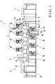
- a sheet-fed rotary printing press 1 comprises a feeder 2 which feeds a sheet (transfer target body), a printing unit 3 which prints the sheet fed from the feeder 2, a coating unit 4 which coats (by transfer) the obverse and reverse of the sheet printed by the printing unit 3 with varnish (transfer liquid), and a delivery unit 5 to which the sheet coated by the coating unit 4 is delivered.
- the printing unit 3 comprises first to fourth obverse printing units 6A to 6D and first to fourth reverse printing units 7A to 7D.
- the sheet-fed rotary printing press 1 serves as a liquid transfer machine.
- the feeder 2 serves as a supply unit.
- the printing unit 3 and coating unit 4 serve as a liquid transfer unit.
- the delivery unit 5 serves as a discharge unit.
- Each of the four obverse printing units 6A to 6D comprises an impression cylinder 10a having a gripper unit in its circumferential surface to grip a sheet, a blanket cylinder 11a opposing the upper portion of the impression cylinder 10a, a plate cylinder 12a opposing the upper portion of the blanket cylinder 11a, and an ink supply unit 13a which supplies ink (transfer target liquid) to the plate cylinder 12a.
- the impression cylinder 10a comprises a double-diameter cylinder having a diameter twice that of the plate cylinder 12a.
- the gripper unit serves as a holding unit.
- the impression cylinder 10a serves as a transport cylinder.
- the blanket cylinder 11a serves as a printing cylinder.
- Each of the four reverse printing units 7A to 7D comprises an impression cylinder 10b having a gripper unit in its circumferential surface to grip a sheet, a blanket cylinder 11b opposing the lower portion of the impression cylinder 10b, a plate cylinder 12b opposing the lower portion of the blanket cylinder 11b, and an ink supply unit 13b which supplies the ink to the plate cylinder 12b.
- the impression cylinder 10b comprises a double-diameter cylinder having a diameter twice that of the plate cylinder 12b.
- the gripper unit serves as a holding unit.
- the impression cylinder 10b serves as a transport cylinder.
- the blanket cylinder 11b serves as a printing cylinder.
- the leading edge of a sheet fed from the feeder 2 onto a feeder board 15 is gripped by a swing arm shaft pregripper 16 and then gripping-changed to the gripper of a transfer cylinder 17.
- the sheet gripping-changed to the gripper of the transfer cylinder 17 is gripping-changed to the gripper of the impression cylinder 10a of the obverse printing unit 6A and printed with the first color on its obverse as the sheet passes through the opposing point (contact point) of the impression cylinder 10a and blanket cylinder 11a.
- the sheet printed with the first color on the obverse is gripping-changed to the impression cylinder 10b of the reverse printing unit 7A and printed with the first color on its reverse as the sheet passes through the opposing point of the impression cylinder 10b and blanket cylinder 11b.
- the sheet which is sequentially printed with the second to fourth colors on each of its obverse and reverse by the obverse printing units 6B to 6D and reverse printing units 7B to 7D is coated with varnish on the obverse and reverse by the coating unit 4.
- the coated sheet is gripping-changed to the delivery gripper (not shown) of a delivery chain 19 of the delivery unit 5 and conveyed by the delivery chain 19.
- the sheet conveyed by the delivery chain 19 serving as a delivery pile is dropped onto a delivery pile 20 and stacked there.
- an upper plate cylinder 21 (first cylinder) has a notch 21a extending in the axial direction in part of its circumferential surface.
- a varnish supply device 22 (first liquid supply means) which supplies the varnish to the upper plate cylinder 21 comprises an anilox roller 23 which is arranged to oppose the upper plate cylinder 21 and a chamber coater 24 which supplies the varnish to the anilox roller 23.
- An upper blanket cylinder 25 (second cylinder) arranged to oppose the upper plate cylinder 21 and a blanket cylinder 26 (third cylinder) has a notch 25a extending in the axial direction in part of its circumferential surface.
- the blanket cylinder 26 has notches 26a extending in the axial direction at positions that halve the circumferential surface in the circumferential direction. Each notch 26a is provided with a gripper unit 27 (sheet holding means) having a gripper pad, which grips and conveys the sheet, and a gripper.
- a lower plate cylinder 28 (fourth cylinder) arranged to oppose the blanket cylinder 26 has a notch 28a extending in the axial direction in part of its circumferential surface.
- a varnish supply device 29 (second liquid supply means) which supplies the varnish to the lower plate cylinder 28 comprises an anilox roller 30 arranged to oppose the lower plate cylinder 28, and a chamber coater 31 which supplies the varnish to the anilox roller 30.
- the blanket cylinder 26 is arranged to oppose the impression cylinder 10b of the reverse printing unit 7D which serves as the most-downstream transport cylinder of the printing unit 3 in the sheet convey direction.
- the upper blanket cylinder 25 and blanket cylinder 26 are arranged to oppose each other in the downstream sheet convey direction from a position where the impression cylinder 10b of the reverse printing unit 7D opposes the blanket cylinder 26.
- the lower plate cylinder 28 and blanket cylinder 26 are arranged to oppose each other in the upstream sheet convey direction from a position where the impression cylinder 10b of the reverse printing unit 7D opposes the blanket cylinder 26.
- the varnish supplied from the chamber coater 24 to the anilox roller 23 is transferred to the upper blanket cylinder 25 through the upper plate cylinder 21.
- the varnish transferred from the lower plate cylinder 28 to the circumferential surface of the blanket cylinder 26 by the printing pressure of the upper blanket cylinder 25 coats the reverse (the other surface) of the printed sheet.
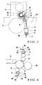
- a pair of frames 35 arranged to oppose each other at a predetermined gap rotatably, axially support the two end shafts of each of the blanket cylinder 26 and upper plate cylinder 21 through bearings (not shown).
- Eccentric bearings 36 fitted on the pair of frames 35 rotatably, axially support two end shafts 25b of the upper blanket cylinder 25.
- a stud 37 projecting outward from one frame 35 near one end shaft of the blanket cylinder 26 supports a bracket 38.
- a stepping motor 39 serving as a driving device is attached to the bracket 38 with a driving rod 40 standing vertically.
- a connecting lever 42 having an L shape when seen from the front is axially mounted on the projecting portion of a lever shaft 41 which is located above the driving rod 40 and the two ends of which are axially supported by the pair of frames 35.
- Each eccentric bearing 36 has an outer ring (not shown) fitted with a housing mounted in the bearing hole of the corresponding frame 35 through a needle roller and an inner ring (not shown) rotatably fitted in the outer ring through a tapered roller.
- a bearing lever 43 fixed to the outer ring of the eccentric bearing 36 is connected to the connecting lever 42 through a rod 44.
- the axis of the inner circumferential surface of the inner ring that constitutes the eccentric bearing 36 is eccentric from that of the outer circumferential surface of the outer ring that constitutes the eccentric bearing 36 by a predetermined distance. Accordingly, in the thrown-on state of the upper blanket cylinder 25, when the rod 40 of the stepping motor 39 moves backward, the axis of the inner circumferential surface of the inner ring moves about the axis of the outer circumferential surface of the outer ring as the center. Accordingly, the upper blanket cylinder 25 is spaced apart from the blanket cylinder 26 and upper plate cylinder 21 to form a gap between the two cylinders 21 and 26, thus performing impression throw-off.
- the eccentric bearing (not shown) of the lower plate cylinder 28 is provided with a similar mechanism which is driven by a stepping motor (not shown) to pivot the eccentric bearing. Accordingly, regarding the lower plate cylinder 28 as well, when the eccentric bearing pivots upon rotation of the stepping motor, the lower plate cylinder 28 is spaced apart from the blanket cylinder 26 to form a gap with respect to the blanket cylinder 26, thus performing impression throw-off.
- An upper anilox roller throw-on/off mechanism 45A which throws the anilox roller 23 which forms the varnish supply device 22 on/off the upper plate cylinder 21, and a lower anilox roller throw-on/off mechanism 45B which throws the anilox roller 30, forming the varnish supply device 29, on/off the lower plate cylinder 28 will be described with reference to Fig. 4 .
- the upper anilox roller throw-on/off mechanism 45A will be described.
- the anilox roller 23 is pivotally supported by the frames 35 through eccentric bearings 23a.
- the proximal end of a bearing lever 48A is fixed to the outer ring of the corresponding eccentric bearing 23a.
- the swing end of the bearing lever 48A is pivotally mounted on a rod 47A of an air cylinder 46A the cylinder end of which is pivotally mounted on the corresponding frame 35. In this arrangement, when the rod 47A of the air cylinder 46A moves forward/backward, the anilox roller 23 is thrown on/off the upper plate cylinder 21 through the bearing lever 48A.
- the lower anilox roller throw-on/off mechanism 45B will be described.
- the anilox roller 30 is pivotally supported by the frames 35 through eccentric bearings 30a.
- the proximal end of a bearing lever 48B is fixed to the outer ring of the corresponding eccentric bearing 30a.
- the swing end of the bearing lever 48B is pivotally mounted on a rod 47B of an air cylinder 46B the cylinder end of which is pivotally mounted on the corresponding frame 35.
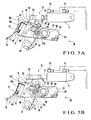
- a cleaning apparatus 50 will be described with reference to Fig. 2 and Figs. 5A and 5B .
- the cleaning apparatus 50 is arranged upstream of a position where the upper blanket cylinder 25 opposes the blanket cylinder 26 in the rotational direction of the upper blanket cylinder 25, to be close to the circumferential surface of the upper blanket cylinder 25.
- the cleaning apparatus 50 comprises a pair of unit frames 52 attached to a stay 51, serving as a contact member and guide member, to be parallel to each other.
- a cleaning unit 55 having the stay 51 and the pair of unit frames 52 is detachably fixed to the driving lever 53.
- a cleaning plate 56a with a U-shaped section and serving as a contact member and press member, which has almost the same width as that of the upper blanket cylinder 25, is attached to the stay 51 to be almost parallel to the upper blanket cylinder 25.
- a cleaning nozzle 57 (third cleaning liquid supply means) which discharges solvent and water is attached to the stay 51.
- a supply roller 60 comprising a cylindrical supply shaft 58 and a cleaning web 59 which is wound around the supply shaft 58 in advance is axially supported at almost the center of the pair of unit frames 52 to be rotatable and detachable.
- a take-up roller 62 comprising a cylindrical take-up shaft 61 and the cleaning web 59 which is to be taken up around the take-up shaft 61 is axially supported between the pair of unit frames 52, at a position closer to the upper blanket cylinder 25 than the shaft member 58, to be rotatable and detachable.
- the cleaning web 59 is guided by the end face of the stay 51 and the cleaning plate 56a and taken up by the take-up roller 62. At this time, the end face of the stay 51 serves as a guide portion.
- a cleaning web take-up lever 63 has an almost V-shaped cam surface 63a.
- a roller 64 is pivotally mounted on one end of the lever 63.
- the central portion of the lever 63 is connected to the take-up shaft 61 through a one-way clutch (not shown).
- the lever 63 transmits to the take-up shaft 61 the pivot motion only in a direction to take up the cleaning web 59, i.e., clockwise in Figs. 5A and 5B , through the one-way clutch.
- the pulling force of a tensile coil spring 65 biases the lever 63 in such a direction that the roller 64 comes close to a pin 70.
- a roller 68 is pivotally mounted on one end of a constant-pitch-feed lever 66 through a shaft 67.
- the other end of the lever 66 is pivotally, axially supported by one unit frame 52.
- the pulling force of a tensile coil spring 69 urges the roller 68 against the take-up roller 62, so the shaft 67 engages with the cam surface 63a of the lever 63.
- the roller 68 moves in a direction to separate from the axis of the take-up shaft 61, so the lever 66 pivots counterclockwise.
- the pin 70 which abuts against the lever 63 to actuate it extends vertically between the frames 35.
- the air cylinder 71 (moving means/cleaning unit throw-on/off means) moves the cleaning web 59 in directions to come into contact with and separate from the upper blanket cylinder 25, and throws the cleaning unit 55 on/off the upper blanket cylinder 25.
- the air cylinder 71 has the actuation rod 72 that can move forward/backward.
- the upper end of the driving lever 53 is pivotally mounted on the distal end of the actuation rod 72.
- the air cylinder 71 has two ports Pa and Pb. When air is supplied to the port Pa, the actuation rod 72 moves forward. When air is supplied to the port Pb, the actuation rod 72 moves backward.
- the air cylinder 71 constitutes a switching means for switching the cleaning/non-cleaning operation of the cleaning apparatus.
- the air cylinder 71, lever 63, roller 64, and pin 70 constitute a feeding mechanism 73 (feed means) which causes the cleaning web 59 to travel.
- the cleaning unit 55 can be stopped immediately before the cleaning web 59 comes into contact with the circumferential surface of the upper blanket cylinder 25.
- a cleaning liquid supply device 75A (first cleaning liquid supply means) which supplies the cleaning liquid to the circumferential surface of the upper plate cylinder 21, and a cleaning liquid supply device 75B (second cleaning liquid supply means) which supplies the cleaning liquid to the circumferential surface of the blanket cylinder 26 will be described with reference to Figs. 2 and 6 .
- the two cleaning liquid supply devices 75A and 75B have the same structure, only the cleaning liquid supply device 75A will be described in detail, and the second cleaning liquid supply device 75B will be described where necessary.
- a stay 76 horizontally extends between the pair of frames 35 such that its axial direction is parallel to that of the upper plate cylinder 21.
- a plurality of upper sprays 77A are attached to the stay 76 at predetermined intervals to oppose the upper plate cylinder 21 throughout the entire axial direction.
- a mistlike cleaning liquid 78 is blown together with the supplied air to the circumferential surface of the upper plate cylinder 21.
- a stay (not shown) horizontally extends between the pair of frames 35 such that its axial direction is parallel to that of the blanket cylinder 26.
- a plurality of lower sprays 77B are attached to the stay at predetermined intervals to oppose the blanket cylinder 26 throughout the entire axial direction.
- the mistlike cleaning liquid 78 is blown together with the supplied air to the circumferential surface of the blanket cylinder 26.
- the cleaning apparatus comprises, in addition to the upper blanket cylinder throw-on/off mechanism 33A, lower plate cylinder throw-on/off mechanism 33B, upper anilox roller throw-on/off mechanism 45A, and lower anilox roller throw-on/off mechanism 45B described above, a cleaning unit throw-on/off solenoid valve 55a, cleaning switch 80, driving device 81, rotary encoder 82, sheet thickness input device 83, spray frequency setter 84, initial web feed frequency setter 85, web feed frequency setter 86, post-cleaning web feed frequency setter 87, drying time setter 88, cleaning unit ON time setter 89, timer 90, upper spray solenoid valve 91, lower spray solenoid valve 92, and controller 93 which is connected to the respective elements described above.
- the cleaning unit throw-on/off solenoid valve 55a performs switching between the ports Pa and Pb of the air cylinder 71.
- the cleaning switch 80 instructs the controller 93 to start cleaning.
- the driving device 81 drives the printing press on the basis of the control of the controller 93.
- the rotary encoder 82 (phase detection means) detects the phase of the transfer cylinder 17.
- the operator inputs the value of the sheet thickness to the sheet thickness input device 83 (thickness input means).
- the operator sets the frequency or the number of times with which the upper sprays 77A and lower sprays 77B blow the cleaning liquid 78.
- the operator sets in the initial web feed frequency setter 85 (initial web feed frequency setting means) the frequency with which the cleaning web 59 is fed before the cleaning apparatus 50 performs cleaning.
- the feed frequency of the cleaning web 59 during the cleaning operation of the cleaning apparatus 50 is set in the web feed frequency setter 86 (web feed frequency setting means).
- the feed frequency of the cleaning web 59 after the cleaning operation of the cleaning apparatus 50 is set in the web feed frequency setter 87 (web feed frequency setting means).
- the cylinder drying time after the cleaning operation of the cleaning apparatus 50 is set in the drying time setter 88 (drying time setting means).
- the time during which the cleaning web 59 of the cleaning apparatus 50 is to be urged against the circumferential surface of the upper blanket cylinder 25 is set in the cleaning unit ON time setter 89 (cleaning unit ON time setting means).
- the timer 90 counts the drying time set in the drying time setter 88 and the time set in the cleaning unit ON time setter 89.
- the upper spray solenoid valve 91 is opened when supplying air to the upper sprays 77A.
- the lower spray solenoid valve 92 is opened when supplying air to the lower sprays 77B.
- Each of the sheet thickness input device 83, spray frequency setter 84, initial web feed frequency setter 85, web feed frequency setter 86, post-cleaning web feed frequency setter 87, drying time setter 88, and cleaning unit ON time setter 89 comprises a ten-key input device to which the operator inputs desired data.
- the operator may select an input mode at one ten-key input device, e.g., a personal computer, which has a plurality of inputs modes corresponding to the types of data, and input a necessary type of data. If the value of the data is fixed and only the fixed data need be read out, a memory may be used.
- the controller 93 closes the upper spray solenoid valve 91 to stop blowing the cleaning liquid from the upper sprays 77A.
- the controller 93 closes the lower spray solenoid valve 92 to stop blowing the cleaning liquid from the lower sprays 77B. This prevents the cleaning liquid blown from the upper sprays 77A and lower sprays 77B from entering the notches 21a and 26a of the upper plate cylinder 21 and blanket cylinder 26, respectively.
- the controller 93 drives the upper blanket cylinder throw-on/off mechanism 33A to control the gap between the upper blanket cylinder 25 and blanket cylinder 26 during printing to provide a printing pressure corresponding to a sheet thickness input to the sheet thickness input device 83 is obtained.
- the controller 93 performs the following control when cleaning the cylinder. Namely, the controller 93 controls the upper blanket cylinder throw-on/off mechanism 33A to throw (bring) the upper blanket cylinder 25 on (into contact with) the upper plate cylinder 21 and blanket cylinder 26. The controller 93 also controls the lower plate cylinder throw-on/off mechanism 33B to throw (bring) the lower plate cylinder 28 on (into contact with) the blanket cylinder 26. The controller 93 turns off the upper anilox roller throw-on/off mechanism 45A so that the anilox roller 23 is thrown off the upper plate cylinder 21. The controller 93 also turns off the upper anilox roller throw-on/off mechanism 45B so that the anilox roller 30 is thrown off the lower plate cylinder 28.
- the controller 93 detects that the cleaning switch 80 is turned on (YES in step S1).
- the controller 93 then operates the printing machine by the driving device 81 at a prefixed cleaning speed (step S2).
- the controller 93 stores the current sheet thickness preset value (step S3).
- the operator sets (inputs) a sheet thickness in the sheet thickness input device 83 (step S4).
- the controller 93 turns off the upper anilox roller throw-on/off mechanism 45A and lower anilox roller throw-on/off mechanism 45B (step S5).
- the anilox roller 23 of the first varnish supply device 22 is thrown off the upper plate cylinder 21, and the anilox roller 30 of the second varnish supply device 29 is thrown off the lower plate cylinder 28.
- the controller 93 turns on the upper blanket cylinder throw-on/off mechanism 33A and lower plate cylinder throw-on/off mechanism 33B (step S6).
- the upper blanket cylinder 25 is thrown on the upper plate cylinder 21 and blanket cylinder 26 and the lower plate cylinder 28 is thrown on the blanket cylinder 26 on the basis of the cleaning sheet thickness value set in the sheet thickness input device 83.
- the contact pressure of the upper blanket cylinder 25 against the blanket cylinder 26 during cleaning becomes a predetermined cleaning pressure having a cleaning function. In this case, a constant cleaning pressure is obtained during cleaning regardless of the sheet thickness value.
- the controller 93 then controls the upper sprays 77A of the first cleaning liquid supply device 75A (step S7).
- Fig. 9 shows step S7 in detail.
- step S11 If an output from the rotary encoder 82 does not indicate an upper spray injection start phase (NO in step S11), that is, if the cleaning liquid injection range of the upper sprays 77A includes the notch 21a of the upper plate cylinder 21, spray injection start is waited until the phase corresponding to the notch 21a is ended.
- step S11 When the upper spray injection start phase is obtained (YES in step S11), that is, when the notch 21a of the upper plate cylinder 21 that has opposed the upper sprays 77A passes, the upper spray solenoid valve 91 is turned on (step S12). Thus, the upper sprays 77A blow the mistlike cleaning liquid 78 to the circumferential surface of the upper plate cylinder 21. Then, when the upper spray injection start phase is not obtained (NO in step S13), that is, when the notch 21a of the upper plate cylinder 21 does not oppose the upper sprays 77A, spray injection is continued until the notch 21a opposes the upper sprays 77A.
- steps S8 to S14 when the upper sprays 77A supply the cleaning liquid 78 to the circumferential surface of the upper plate cylinder 21, as the upper plate cylinder 21 rotates, the cleaning liquid 78 dissolves the varnish attached to the circumferential surface of the upper plate cylinder 21 to decrease its viscosity.
- the cleaning liquid 78 supplied to the circumferential surface of the upper plate cylinder 21 transfers to the upper blanket cylinder 25 which has been thrown on the upper plate cylinder 21, to decrease the viscosity of the varnish attached to the circumferential surface of the upper blanket cylinder 25 as well.
- the controller 93 controls the lower sprays 77B of the second cleaning liquid supply device 75B (step S15) as well as the upper sprays 77A of the first cleaning liquid supply device 75A (step S7).
- Fig. 10 shows step S15 in detail.
- step S17 When the lower spray injection start phase is obtained (YES in step S17), that is, when the notch 26a of the blanket cylinder 26 that has opposed the lower sprays 77B passes, the lower spray solenoid valve 92 is turned on (step S18). Thus, the lower sprays 77B blow the mistlike cleaning liquid 78 to the circumferential surface of the blanket cylinder 26. Then, when the lower spray start phase is not obtained (NO in step S19), that is, when the cleaning liquid injection range of the lower sprays 77B includes the notch 26a of the blanket cylinder 26, spray injection is continued until the phase corresponding to the notch 26a is ended.
- steps S16 to S22 when the lower sprays 77B supply the cleaning liquid 78 to the circumferential surface of the blanket cylinder 26, as the blanket cylinder 26 rotates, the cleaning liquid 78 dissolves the varnish attached to the circumferential surface of the blanket cylinder 26 to decrease its viscosity.
- the cleaning liquid 78 supplied to the circumferential surface of the blanket cylinder 26 transfers to the lower plate cylinder 28 and upper blanket cylinder 25 which have been thrown on the blanket cylinder 26, to decrease the viscosity of the varnish attached to the circumferential surfaces of the lower plate cylinder 28 and upper blanket cylinder 25 as well.
- control operation is performed so the cleaning liquid will not be supplied to the notch 21a of the upper plate cylinder 21 or the notch 26a of the blanket cylinder 26 provided with the gripper or the like. This prevents waste of the cleaning liquid and contamination and rust of the rollers, thus improving the durability.
- step S23 the cleaning unit performs cleaning
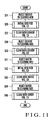
- Fig. 11 shows step S23 in detail.
- the cleaning apparatus 50 injects the cleaning liquid 78 to the cleaning web 59 from the cleaning nozzle 57 (step S24) .
- step S25 initial web feed takes place (step S25).
- Fig. 12 shows step S25 in detail.
- the air cylinder 71 is turned on (step S28). More specifically, when the solenoid valve 55a is switched, as shown in Fig. 5B , air is supplied to the port Pa of the air cylinder 71 to move the actuation rod 72 forward, and the cleaning plate 56a comes close to the circumferential surface of the upper blanket cylinder 25.
- step S29 It is checked whether the time (throw-on operation time of the air cylinder 71) that the timer 90 counts and lapses until the air cylinder 71 is turned off, before the cleaning web 59 comes into contact with the circumferential surface of the upper blanket cylinder 25, reaches a predetermined period of time (step S29). If the throw-on operation time of the air cylinder 71 does not reach the predetermined period of time (NO in step S29), it is waited until the predetermined period of time elapses. If the throw-on time of the air cylinder 71 reaches the predetermined period of time (YES in step S29), the air cylinder 71 is turned off (step S30).
- the cleaning web 59 travels without coming into contact with the circumferential surface of the cylinder in step S24, and that portion of the cleaning web 59 to which the cleaning liquid 78 has been supplied opposes the circumferential surface of the cylinder. This prevents that portion of the cleaning web 59 which is not soaked with the solvent from coming into contact with the circumferential surface of the cylinder and adhering to it at the start of cleaning.
- step S32 the cleaning apparatus 50 performs first cleaning using the solvent (step S32).
- Fig. 13 shows step S32 in detail.
- the air cylinder 71 is turned on (step S35). More specifically, as shown in Fig. 5B , air is supplied to the port Pa of the air cylinder 71 to move the actuation rod 72 forward, and the cleaning plate 56a urges the cleaning web 59 against the circumferential surface of the upper blanket cylinder 25 in a still state.
- step S36 It is checked whether the time (the time during which the cleaning web 59 is in contact with the circumferential surface of the upper blanket cylinder 25) which is counted by the timer 90 and set by the cleaning unit ON time setter 89 reaches a predetermined period of time (step S36). If the throw-on operation time of the air cylinder 71 does not reach the predetermined period of time (NO in step S29), it is waited until the predetermined period of time elapses. If the throw-on time of the air cylinder 71 reaches the predetermined period of time, the air cylinder 71 is turned off (step S37).
- the preset value in this case, the preset value "j1" of first solvent cleaning
- the upper blanket cylinder 25 is kept thrown on the upper plate cylinder 21 and blanket cylinder 26, and the lower plate cylinder 28 is kept thrown on the blanket cylinder 26.
- the varnish or contamination on the upper plate cylinder 21, blanket cylinder 26, and lower plate cylinder 28 is transferred to the upper blanket cylinder 25 and cleaned by the cleaning apparatus 50.
- each of the cylinders 21, 25, 26, and 28 to be cleaned need not be provided with an individual cleaning apparatus 50, but one cleaning apparatus can clean the plurality of cylinders.
- This can reduce the cost and the space to install the cleaning apparatus. Since the cleaning apparatus 50 cleans the cylinders 21, 25, 26, and 28 simultaneously, waste paper due to cleaning by printing is not produced. Hence, the cost does not increase, and the operation of removing the waste paper from the delivery pile becomes unnecessary, thus reducing the load to the operator.
- step S39 the cleaning apparatus 50 injects the solvent to the cleaning web 59 from its cleaning nozzle (step S39).
- step S40 the cleaning apparatus 50 performs second cleaning using the solvent (step S40).
- Fig. 13 shows step S40 in detail. As the second cleaning is almost the same as the first cleaning (step S32), only the difference will be described.
- step S38 in Fig. 13 whether or not the preset value "j" has reached the preset value "j2" of second solvent cleaning is checked.
- the preset value "j2" of the throw-on frequency of the cleaning unit is set to be larger than that of the preset value "j1" of the first cleaning operation (step S32). This is due to the following reason.
- the throw-on frequency of the cleaning unit is set larger than that of the first cleaning operation (the cleaning time of the cleaning apparatus 50 is prolonged), so that when wiping the contamination and cleaning liquid attached to the circumferential surface of the cylinder, cleaning with water can be performed after the solvent of the cleaning liquid 78 is dried sufficiently.
- step S40 the cleaning apparatus 50 injects water to the cleaning web 59 from its cleaning nozzle 57 (step S41).
- step S42 second initial web feed is performed (step S42).
- the operation of the second initial web feed is the same as that of the first initial web feed (step S25) and a repetitive description thereof will be omitted.
- step S43 the cleaning apparatus 50 performs first cleaning using water (step S43).
- Fig. 13 shows step S43 in detail. As the first water cleaning is almost the same as the first solvent cleaning (step S32), only the difference will be described.
- step S38 in Fig. 13 whether or not the preset value "j" has reached the preset value "j3" of the first water cleaning is checked.
- step S44 the cleaning apparatus 50 injects water to the cleaning web 59 from its cleaning nozzle (step S44).
- step S44 in Fig. 11 the cleaning apparatus 50 performs second water cleaning.
- Fig. 13 shows step S43 in detail. As the second cleaning with water is almost the same as the first solvent cleaning (step S32), only the difference will be described.
- step S38 in Fig. 13 whether or not the preset value "j" has reached the preset value "j4" of the second water cleaning is checked.
- steps S7 and S15 the cleaning liquid is supplied to the circumferential surfaces of the upper plate cylinder 21 and blanket cylinder 26.
- the respective cylinders 21, 25, 26, and 28 are not cleaned by the cleaning apparatus 50 but rotated.
- the varnish attached to the circumferential surface of each of the plurality of cylinders 21, 25, 26, and 28 which are kept thrown on each other and are thus continuous to each other dissolves, so its viscosity decreases.
- the cylinders 21, 25, 26, and 28 are cleaned by the cleaning apparatus 50. This facilitates removal of the varnish and contamination, thus shortening the cleaning time.
- the controller 93 controls the driving device 81 to operate the printing press at a high speed so as to dry the circumferential surfaces of the upper plate cylinder 21, upper blanket cylinder 25, blanket cylinder 26, and lower plate cylinder 28 that are cleaned (step S46).
- the printing press continues high-speed operation until the time preset by the drying time setter 88 elapses (step S47).
- the controller 93 controls the driving device 81 to switch the printing press to low-speed operation (step S48). Then, the controller 93 turns off the upper blanket cylinder throw-on/off mechanism 33A and lower plate cylinder throw-on/off mechanism 33B, so that the upper blanket cylinder 25 and lower plate cylinder 28 are thrown off the blanket cylinder 26. The controller 93 then sets the sheet thickness value to the stored value of immediately before cleaning.
- step S51 When the printing press is operated at a high speed in step S46, post-cleaning web feed is performed simultaneously (step S51).
- Fig. 14 shows step S51 in detail.
- the air cylinder 71 is turned on (step S54). More specifically, when the solenoid valve 55a is switched, as shown in Fig. 5B , air is supplied to the port Pa of the air cylinder 71 to move the actuation rod 72 forward, and the cleaning plate 56a comes close to the circumferential surface of the upper blanket cylinder 25.
- step S55 It is checked whether the time (throw-on operation time of the air cylinder 71) that the timer 90 counts and lapses until the air cylinder 71 is turned off, before the cleaning web 59 comes into contact with the circumferential surface of the upper blanket cylinder 25, reaches a predetermined period of time (step S55). If the throw-on operation time of the air cylinder 71 does not reach the predetermined period of time (NO in step S55), it is waited until the predetermined period of time elapses. If the throw-on time of the air cylinder 71 reaches the predetermined period of time (YES in step S55), the air cylinder 71 is turned off (step S56). Thus, the cleaning unit 55 is spaced apart from the upper blanket cylinder 25 immediately before the cleaning web 59 comes into contact with the upper blanket cylinder 25.
- the predetermined length refers to a length which is equal to or larger than the length (the length from point A to point B in Figs. 5A and 5B ) with which the cleaning web 59 is in contact with the stay 51, the cleaning plate 56a, and a guide member 56b as the contact members and with which the cleaning web 59 can wipe the contamination transferred to the stay 51, cleaning plate 56a, and guide member 56b.
- the predetermined length of the cleaning web 59 corresponds to a clean (unused) portion of the cleaning web 59 which comes into contact with the contact members to wipe their contamination.
- step S23 the cleaning web 59 is driven to travel for the predetermined length in step S51.
- This can prevent the contamination removed from the circumferential surface of the upper blanket cylinder 25 from being attached to the cleaning web 59 to stick the cleaning web 59 to the stay 51, cleaning plate 56a, and guide member 56b.
- the cleaning web 59 can be prevented from failing to travel. This can prevent deformation of a cleaning pad 56 or any damage to the cleaning apparatus 50.
- the traveling cleaning web 59 travels to clean the upper blanket cylinder 25 in step S51, before the contamination attached to the cleaning web 59 sticks to the stay 51, cleaning plate 56a, and guide member 56b, the contaminated cleaning web 59 can be spaced apart from the stay 51, cleaning plate 56a, and guide member 56b. Therefore, the varnish, contamination, and the like attached to the cleaning web 59 will not solidify on the stay 51, cleaning plate 56a, and guide member 56b. Hence, unlike in the conventional case, the operation of manually removing the varnish or contamination attached to and solidifying on the stay 51, cleaning plate 56a, and guide member 56b becomes unnecessary, thus reducing the load to the operator.
- the cleaning web 59 that has caused to travel in step S51 can remove the varnish or contamination attached to the stay 51, cleaning plate 56a, and guide member 56b. Therefore, unlike in the conventional case, the operation of manually removing the varnish or contamination attached to and solidifying on the stay 51, cleaning plate 56a, and guide member 56b becomes unnecessary, thus reducing the load of the cleaning operation.
- the printing press is operated at the maximal speed for normal printing operation in step S46 to dry the respective cylinders. Simultaneously to this, the cleaning web 59 is caused to travel in step S51. Since drying of the cylinders and the travel of the cleaning web 59 are performed simultaneously in this manner after cleaning the cylinders, the preparation time until the start of printing as the next operation can be shortened.
- the cleaning liquid supply devices 75A and 75B supply the cleaning liquid to the two cylinders, i.e., the upper plate cylinder 21 and blanket cylinder 26, separately, the time required for cleaning can be shortened.
- the cleaning liquid supply devices 75A and 75B may constitute one device where necessary, or the cleaning liquid supply device 75A may serve to blow the cleaning liquid to the circumferential surface of the upper blanket cylinder 25. Since the cleaning apparatus 50 is provided with the cleaning nozzle 57 which serves as the third cleaning liquid supply device, the cleaning ability is improved to shorten the time required for cleaning.
- the cleaning liquid supply device 75A supplies the cleaning liquid to the upper plate cylinder 21 directly.
- the cleaning liquid supply device 75A supplies the cleaning liquid to the upper blanket cylinder 25, and indirectly to the upper plate cylinder 21 through the upper blanket cylinder 25.
- the cleaning liquid supply device 75B supplies the cleaning liquid to the blanket cylinder 26 directly.
- the cleaning liquid supply device 75B supplies the cleaning liquid to the lower plate cylinder 28, and indirectly to the blanket cylinder 26 through the lower plate cylinder 28.
- this embodiment exemplifies cleaning of varnish in the coating device, it can also be applied to cleaning of ink in the printing press.
- the sheet is employed as the object to which the varnish or ink transfers, a web may replace the sheet.
- the cleaning operation is performed while the lower plate cylinder 28 is kept thrown on the blanket cylinder 26.
- the lower plate cylinder 28 may be thrown off the blanket cylinder 26, and the three cylinders, i.e., the upper plate cylinder 21, upper blanket cylinder 25, and blanket cylinder 26 may be thrown on each other and cleaned.
- the cylinders that come into contact with each other only during printing/coating are brought into contact with each other during cleaning.
- the cylinders that do not usually come into contact with each other are brought into contact with each other for cleaning, and are cleaned.
- the respective cylinders are not provided with separate cleaning apparatuses, but the plurality of cylinders can be cleaned by one common cleaning apparatus. According to the present invention, the cost can be reduced, and the space to install the cleaning apparatus can be decreased.
- the cleaning apparatus cleans the cylinders, waste paper due to cleaning by printing is not produced, and accordingly the cost does not increase. Also, the operation of removing the waste paper from the delivery pile becomes unnecessary, thus reducing the load to the operator.
Landscapes
- Engineering & Computer Science (AREA)
- Mechanical Engineering (AREA)
- Inking, Control Or Cleaning Of Printing Machines (AREA)
- Cleaning In General (AREA)
- Cleaning By Liquid Or Steam (AREA)
Abstract
Description
- The present invention relates to a cleaning apparatus which cleans a cylinder in a transfer device (coating device/printing device) which performs transfer (coating/printing) on a transfer target body (sheet/web).
- A conventional printing apparatus comprises a printing unit which prints a sheet fed from a feeder, a coater cylinder which coats the sheet printed by the printing unit, and a varnish roller which transfers varnish onto the coater cylinder. In a conventional cleaning apparatus in the printing apparatus having the above arrangement, as disclosed in Japanese Patent Laid-Open No.
2000-289190 - The conventional cleaning apparatus described above performs so-called "cleaning by printing" in which the varnish attached to the circumferential surface of the coater cylinder is transferred to the sheet, thus cleaning the coater cylinder. This accompanies wasted paper and increases the cost particularly when the sheet is expensive. It also requires the operation of removing the cleaning waste paper stacked on the delivery pile, increasing the load to the operator.
- It is an object of the present invention to provide a cleaning apparatus in which waste paper is eliminated to reduce the cost.
- It is another object of the present invention to provide a cleaning apparatus in which the load to the operator is decreased.
- In order to achieve the above objects, according to the present invention, there is provided a cleaning apparatus comprising first liquid supply means for supplying a transfer liquid to a first cylinder, a second cylinder which performs transfer to one surface of a transfer target body with the transfer liquid transferred from the first cylinder, a cleaning unit which cleans a circumferential surface of the second cylinder in contact therewith, a third cylinder which is arranged to oppose the second cylinder and performs transfer to the other surface of the transfer target body, second liquid supply means for supplying the transfer liquid to the third cylinder, first cleaning liquid supply means for supplying a cleaning liquid to at least one of the first cylinder and the third cylinder, and control means for controlling the cleaning unit to clean the second cylinder while the second cylinder is in contact with the first cylinder and the third cylinder.
-
-
Fig. 1 is a side view showing a sheet-fed rotary printing press as a whole; -
Fig. 2 is a side view of a coating device to which a cleaning apparatus according to an embodiment of the present invention is applied; -
Fig. 3 is a side view of the main part showing a throw-on/off mechanism for an upper blanket cylinder shown inFig. 2 ; -
Fig. 4 is a side view of the main part showing a throw-on/off mechanism for an anilox roller shown inFig. 2 ; -
Figs. 5A and 5B are views showing a non-cleaning state and cleaning state, respectively, of the cleaning apparatus shown inFig. 2 ; -
Fig. 6 is a view seen from the direction of an arrow VI inFig. 2 ; -
Fig. 7 is a block diagram showing the electrical configuration of the cleaning apparatus shown inFig. 7 ; -
Fig. 8 is a flowchart to briefly explain the cleaning operation of the cleaning apparatus shown nFig. 7 ; -
Fig. 9 is a flowchart to explain in detail upper spray control shown inFig. 8 ; -
Fig. 10 is a flowchart to explain in detail lower spray control shown inFig. 8 ; -
Fig. 11 is a flowchart to explain in detail the cleaning operation of a cleaning unit shown inFig. 8 ; -
Fig. 12 is a flowchart to explain initial web feed shown inFig. 11 ; -
Fig. 13 is a flowchart to explain in detail solvent cleaning and water cleaning shown inFig. 11 ; and -
Fig. 14 is a flowchart to explain in detail post-cleaning web feed shown inFig. 8 . - A printing press according to an embodiment of the present invention will be described in detail with reference to
Figs. 1 to 14 . - As shown in
Fig. 1 , a sheet-fedrotary printing press 1 comprises afeeder 2 which feeds a sheet (transfer target body), aprinting unit 3 which prints the sheet fed from thefeeder 2, a coating unit 4 which coats (by transfer) the obverse and reverse of the sheet printed by theprinting unit 3 with varnish (transfer liquid), and adelivery unit 5 to which the sheet coated by the coating unit 4 is delivered. Theprinting unit 3 comprises first to fourthobverse printing units 6A to 6D and first to fourthreverse printing units 7A to 7D. The sheet-fedrotary printing press 1 serves as a liquid transfer machine. Thefeeder 2 serves as a supply unit. Theprinting unit 3 and coating unit 4 serve as a liquid transfer unit. Thedelivery unit 5 serves as a discharge unit. - Each of the four
obverse printing units 6A to 6D comprises animpression cylinder 10a having a gripper unit in its circumferential surface to grip a sheet, ablanket cylinder 11a opposing the upper portion of theimpression cylinder 10a, aplate cylinder 12a opposing the upper portion of theblanket cylinder 11a, and anink supply unit 13a which supplies ink (transfer target liquid) to theplate cylinder 12a. Theimpression cylinder 10a comprises a double-diameter cylinder having a diameter twice that of theplate cylinder 12a. The gripper unit serves as a holding unit. Theimpression cylinder 10a serves as a transport cylinder. Theblanket cylinder 11a serves as a printing cylinder. - Each of the four
reverse printing units 7A to 7D comprises animpression cylinder 10b having a gripper unit in its circumferential surface to grip a sheet, ablanket cylinder 11b opposing the lower portion of theimpression cylinder 10b, aplate cylinder 12b opposing the lower portion of theblanket cylinder 11b, and anink supply unit 13b which supplies the ink to theplate cylinder 12b. Theimpression cylinder 10b comprises a double-diameter cylinder having a diameter twice that of theplate cylinder 12b. The gripper unit serves as a holding unit. Theimpression cylinder 10b serves as a transport cylinder. Theblanket cylinder 11b serves as a printing cylinder. - In this arrangement, the leading edge of a sheet fed from the
feeder 2 onto afeeder board 15 is gripped by a swingarm shaft pregripper 16 and then gripping-changed to the gripper of atransfer cylinder 17. The sheet gripping-changed to the gripper of thetransfer cylinder 17 is gripping-changed to the gripper of theimpression cylinder 10a of theobverse printing unit 6A and printed with the first color on its obverse as the sheet passes through the opposing point (contact point) of theimpression cylinder 10a andblanket cylinder 11a. Then, the sheet printed with the first color on the obverse is gripping-changed to theimpression cylinder 10b of thereverse printing unit 7A and printed with the first color on its reverse as the sheet passes through the opposing point of theimpression cylinder 10b andblanket cylinder 11b. - Subsequently, the sheet which is sequentially printed with the second to fourth colors on each of its obverse and reverse by the
obverse printing units 6B to 6D andreverse printing units 7B to 7D is coated with varnish on the obverse and reverse by the coating unit 4. The coated sheet is gripping-changed to the delivery gripper (not shown) of adelivery chain 19 of thedelivery unit 5 and conveyed by thedelivery chain 19. The sheet conveyed by thedelivery chain 19 serving as a delivery pile is dropped onto adelivery pile 20 and stacked there. - The coating unit 4 will be described with reference to
Fig. 2 . As shown inFig. 2 , an upper plate cylinder 21 (first cylinder) has anotch 21a extending in the axial direction in part of its circumferential surface. A varnish supply device 22 (first liquid supply means) which supplies the varnish to theupper plate cylinder 21 comprises ananilox roller 23 which is arranged to oppose theupper plate cylinder 21 and achamber coater 24 which supplies the varnish to theanilox roller 23. An upper blanket cylinder 25 (second cylinder) arranged to oppose theupper plate cylinder 21 and a blanket cylinder 26 (third cylinder) has anotch 25a extending in the axial direction in part of its circumferential surface. - The
blanket cylinder 26 hasnotches 26a extending in the axial direction at positions that halve the circumferential surface in the circumferential direction. Eachnotch 26a is provided with a gripper unit 27 (sheet holding means) having a gripper pad, which grips and conveys the sheet, and a gripper. A lower plate cylinder 28 (fourth cylinder) arranged to oppose theblanket cylinder 26 has anotch 28a extending in the axial direction in part of its circumferential surface. A varnish supply device 29 (second liquid supply means) which supplies the varnish to thelower plate cylinder 28 comprises ananilox roller 30 arranged to oppose thelower plate cylinder 28, and achamber coater 31 which supplies the varnish to theanilox roller 30. - The
blanket cylinder 26 is arranged to oppose theimpression cylinder 10b of thereverse printing unit 7D which serves as the most-downstream transport cylinder of theprinting unit 3 in the sheet convey direction. Theupper blanket cylinder 25 andblanket cylinder 26 are arranged to oppose each other in the downstream sheet convey direction from a position where theimpression cylinder 10b of thereverse printing unit 7D opposes theblanket cylinder 26. Thelower plate cylinder 28 andblanket cylinder 26 are arranged to oppose each other in the upstream sheet convey direction from a position where theimpression cylinder 10b of thereverse printing unit 7D opposes theblanket cylinder 26. - In this arrangement, the varnish supplied from the
chamber coater 24 to theanilox roller 23 is transferred to theupper blanket cylinder 25 through theupper plate cylinder 21. When the printed sheet passes through the opposing point of theupper blanket cylinder 25 andblanket cylinder 26, its obverse (one surface) is coated. Simultaneously, the varnish transferred from thelower plate cylinder 28 to the circumferential surface of theblanket cylinder 26 by the printing pressure of theupper blanket cylinder 25 coats the reverse (the other surface) of the printed sheet. - Two cylinder throw-on/off mechanisms which throw on/off the
upper blanket cylinder 25 andlower plate cylinder 28 will be described with reference toFig. 3 . As these cylinder throw-on/off mechanisms have the same structure, only an upper blanket cylinder throw-on/offmechanism 33A which engages/releases theupper blanket cylinder 25 will be described in detail. A lower plate cylinder throw-on/offmechanism 33B (Fig. 7 ) which throws on/off thelower plate cylinder 28 will be briefly described where necessary. - A pair of
frames 35 arranged to oppose each other at a predetermined gap rotatably, axially support the two end shafts of each of theblanket cylinder 26 andupper plate cylinder 21 through bearings (not shown).Eccentric bearings 36 fitted on the pair offrames 35 rotatably, axially support twoend shafts 25b of theupper blanket cylinder 25. Astud 37 projecting outward from oneframe 35 near one end shaft of theblanket cylinder 26 supports abracket 38. A steppingmotor 39 serving as a driving device is attached to thebracket 38 with a drivingrod 40 standing vertically. - When a
nut 39a is driven by the steppingmotor 39 to rotate, the drivingrod 40 with a threaded portion threadably engaging with thenut 39a vertically moves. A connectinglever 42 having an L shape when seen from the front is axially mounted on the projecting portion of alever shaft 41 which is located above the drivingrod 40 and the two ends of which are axially supported by the pair offrames 35. - Each
eccentric bearing 36 has an outer ring (not shown) fitted with a housing mounted in the bearing hole of thecorresponding frame 35 through a needle roller and an inner ring (not shown) rotatably fitted in the outer ring through a tapered roller. A bearinglever 43 fixed to the outer ring of theeccentric bearing 36 is connected to the connectinglever 42 through arod 44. When the drivingrod 40 is driven by the steppingmotor 39 to move forward/backward, theeccentric bearing 36 pivots through the connectinglever 42,rod 44, and bearinglever 43. - The axis of the inner circumferential surface of the inner ring that constitutes the
eccentric bearing 36 is eccentric from that of the outer circumferential surface of the outer ring that constitutes theeccentric bearing 36 by a predetermined distance. Accordingly, in the thrown-on state of theupper blanket cylinder 25, when therod 40 of the steppingmotor 39 moves backward, the axis of the inner circumferential surface of the inner ring moves about the axis of the outer circumferential surface of the outer ring as the center. Accordingly, theupper blanket cylinder 25 is spaced apart from theblanket cylinder 26 andupper plate cylinder 21 to form a gap between the twocylinders - The eccentric bearing (not shown) of the
lower plate cylinder 28 is provided with a similar mechanism which is driven by a stepping motor (not shown) to pivot the eccentric bearing. Accordingly, regarding thelower plate cylinder 28 as well, when the eccentric bearing pivots upon rotation of the stepping motor, thelower plate cylinder 28 is spaced apart from theblanket cylinder 26 to form a gap with respect to theblanket cylinder 26, thus performing impression throw-off. - An upper anilox roller throw-on/off
mechanism 45A which throws theanilox roller 23 which forms thevarnish supply device 22 on/off theupper plate cylinder 21, and a lower anilox roller throw-on/offmechanism 45B which throws theanilox roller 30, forming thevarnish supply device 29, on/off thelower plate cylinder 28 will be described with reference toFig. 4 . First, the upper anilox roller throw-on/offmechanism 45A will be described. - The
anilox roller 23 is pivotally supported by theframes 35 througheccentric bearings 23a. The proximal end of a bearinglever 48A is fixed to the outer ring of the correspondingeccentric bearing 23a. The swing end of the bearinglever 48A is pivotally mounted on arod 47A of anair cylinder 46A the cylinder end of which is pivotally mounted on thecorresponding frame 35. In this arrangement, when therod 47A of theair cylinder 46A moves forward/backward, theanilox roller 23 is thrown on/off theupper plate cylinder 21 through the bearinglever 48A. - The lower anilox roller throw-on/off
mechanism 45B will be described. Theanilox roller 30 is pivotally supported by theframes 35 througheccentric bearings 30a. The proximal end of a bearinglever 48B is fixed to the outer ring of the correspondingeccentric bearing 30a. The swing end of the bearinglever 48B is pivotally mounted on arod 47B of anair cylinder 46B the cylinder end of which is pivotally mounted on thecorresponding frame 35. In this arrangement, when therod 47B of theair cylinder 46B moves forward/backward, theanilox roller 30 is thrown on/off thelower plate cylinder 28 through the bearinglever 48B. - A
cleaning apparatus 50 will be described with reference toFig. 2 andFigs. 5A and 5B . As shown inFig. 2 , thecleaning apparatus 50 is arranged upstream of a position where theupper blanket cylinder 25 opposes theblanket cylinder 26 in the rotational direction of theupper blanket cylinder 25, to be close to the circumferential surface of theupper blanket cylinder 25. As shown inFigs. 5A and 5B , thecleaning apparatus 50 comprises a pair of unit frames 52 attached to astay 51, serving as a contact member and guide member, to be parallel to each other. - The lower end of a driving
lever 53 is fixed to ashaft 54 which is pivotally supported between theframes 35. Acleaning unit 55 having thestay 51 and the pair of unit frames 52 is detachably fixed to the drivinglever 53. Acleaning plate 56a with a U-shaped section and serving as a contact member and press member, which has almost the same width as that of theupper blanket cylinder 25, is attached to thestay 51 to be almost parallel to theupper blanket cylinder 25. A cleaning nozzle 57 (third cleaning liquid supply means) which discharges solvent and water is attached to thestay 51. - A
supply roller 60 comprising acylindrical supply shaft 58 and a cleaningweb 59 which is wound around thesupply shaft 58 in advance is axially supported at almost the center of the pair of unit frames 52 to be rotatable and detachable. A take-uproller 62 comprising a cylindrical take-upshaft 61 and the cleaningweb 59 which is to be taken up around the take-upshaft 61 is axially supported between the pair of unit frames 52, at a position closer to theupper blanket cylinder 25 than theshaft member 58, to be rotatable and detachable. The cleaningweb 59 is guided by the end face of thestay 51 and thecleaning plate 56a and taken up by the take-uproller 62. At this time, the end face of thestay 51 serves as a guide portion. - A cleaning web take-up
lever 63 has an almost V-shapedcam surface 63a. Aroller 64 is pivotally mounted on one end of thelever 63. The central portion of thelever 63 is connected to the take-upshaft 61 through a one-way clutch (not shown). Thelever 63 transmits to the take-upshaft 61 the pivot motion only in a direction to take up the cleaningweb 59, i.e., clockwise inFigs. 5A and 5B , through the one-way clutch. The pulling force of atensile coil spring 65 biases thelever 63 in such a direction that theroller 64 comes close to apin 70. - A
roller 68 is pivotally mounted on one end of a constant-pitch-feed lever 66 through ashaft 67. The other end of thelever 66 is pivotally, axially supported by oneunit frame 52. The pulling force of atensile coil spring 69 urges theroller 68 against the take-uproller 62, so theshaft 67 engages with thecam surface 63a of thelever 63. In this arrangement, as the take-upshaft 61 takes up the cleaningweb 59 and the diameter of the take-uproller 62 increases, theroller 68 moves in a direction to separate from the axis of the take-upshaft 61, so thelever 66 pivots counterclockwise. - This changes the engaging position of the
shaft 67 and thecam surface 63a of thelever 63, thus enlarging the gap between apin 70 and theroller 64 which is pivotally mounted on thelever 63. As a result, the pivot angle of thelever 63 which pivots each time anactuation rod 72 of anair cylinder 71 moves forward changes in accordance with the outer diameter of the take-uproller 62. More specifically, when the gap between theroller 64 andpin 70 enlarges, the pivot angle of thelever 63 which pivots each time theactuation rod 72 of theair cylinder 71 moves forward decreases. Therefore, the amount of the cleaningweb 59 taken up by the take-upshaft 61, that is, the feed amount of the cleaningweb 59 is always constant regardless of the outer diameter of the take-uproller 62. - The
pin 70 which abuts against thelever 63 to actuate it extends vertically between theframes 35.
The air cylinder 71 (moving means/cleaning unit throw-on/off means) moves the cleaningweb 59 in directions to come into contact with and separate from theupper blanket cylinder 25, and throws the cleaningunit 55 on/off theupper blanket cylinder 25. Theair cylinder 71 has theactuation rod 72 that can move forward/backward. The upper end of the drivinglever 53 is pivotally mounted on the distal end of theactuation rod 72. Theair cylinder 71 has two ports Pa and Pb. When air is supplied to the port Pa, theactuation rod 72 moves forward. When air is supplied to the port Pb, theactuation rod 72 moves backward. Theair cylinder 71 constitutes a switching means for switching the cleaning/non-cleaning operation of the cleaning apparatus. - When the
actuation rod 72 moves forward from the non-cleaning state shown inFig. 5A , the drivinglever 53 pivots counterclockwise about theshaft 54 as the center, and thecleaning unit 55 moves in the direction to come close theupper blanket cylinder 25. Hence, as shown inFig. 5B , thecleaning plate 56a urges the cleaningweb 59 against the circumferential surface of theupper blanket cylinder 25. At this time, as thecleaning unit 55 moves, theroller 64 abuts against thepin 70, so thelever 63 pivots clockwise. Hence, the take-upshaft 61 pivots clockwise to take up the cleaningweb 59. - In this manner, the
air cylinder 71,lever 63,roller 64, and pin 70 constitute a feeding mechanism 73 (feed means) which causes the cleaningweb 59 to travel. By controlling the amount of air to be supplied to the port Pa, thecleaning unit 55 can be stopped immediately before the cleaningweb 59 comes into contact with the circumferential surface of theupper blanket cylinder 25. - When the
actuation rod 72 moves backward from the cleaning state shown inFig. 5B , the drivinglever 53 pivots clockwise about theshaft 54 as the pivot center, and the cleaningweb 59 separates together with thecleaning unit 55 from the circumferential surface of theupper blanket cylinder 25, as shown inFig. 5A . When thecleaning unit 55 moves, the pulling force of thetensile coil spring 65 pivots thelever 63 counterclockwise. Thus, theroller 64 is restored to the original position to form a gap between theroller 64 andpin 70. - A cleaning
liquid supply device 75A (first cleaning liquid supply means) which supplies the cleaning liquid to the circumferential surface of theupper plate cylinder 21, and a cleaningliquid supply device 75B (second cleaning liquid supply means) which supplies the cleaning liquid to the circumferential surface of theblanket cylinder 26 will be described with reference toFigs. 2 and6 . As the two cleaningliquid supply devices liquid supply device 75A will be described in detail, and the second cleaningliquid supply device 75B will be described where necessary. - As shown in
Fig. 6 , astay 76 horizontally extends between the pair offrames 35 such that its axial direction is parallel to that of theupper plate cylinder 21. In the cleaningliquid supply device 75A, a plurality ofupper sprays 77A are attached to thestay 76 at predetermined intervals to oppose theupper plate cylinder 21 throughout the entire axial direction. When air is supplied to theupper sprays 77A, amistlike cleaning liquid 78 is blown together with the supplied air to the circumferential surface of theupper plate cylinder 21. - Similarly, a stay (not shown) horizontally extends between the pair of
frames 35 such that its axial direction is parallel to that of theblanket cylinder 26. In the cleaningliquid supply device 75B, a plurality oflower sprays 77B are attached to the stay at predetermined intervals to oppose theblanket cylinder 26 throughout the entire axial direction. When air is supplied to thelower sprays 77B, themistlike cleaning liquid 78 is blown together with the supplied air to the circumferential surface of theblanket cylinder 26. - The electrical configuration of the apparatus of this embodiment will be described with reference to
Fig. 7 . The cleaning apparatus according to this embodiment comprises, in addition to the upper blanket cylinder throw-on/offmechanism 33A, lower plate cylinder throw-on/offmechanism 33B, upper anilox roller throw-on/offmechanism 45A, and lower anilox roller throw-on/offmechanism 45B described above, a cleaning unit throw-on/offsolenoid valve 55a, cleaningswitch 80, drivingdevice 81,rotary encoder 82, sheetthickness input device 83,spray frequency setter 84, initial webfeed frequency setter 85, webfeed frequency setter 86, post-cleaning webfeed frequency setter 87, dryingtime setter 88, cleaning unit ONtime setter 89,timer 90, upperspray solenoid valve 91, lowerspray solenoid valve 92, andcontroller 93 which is connected to the respective elements described above. - The cleaning unit throw-on/off
solenoid valve 55a performs switching between the ports Pa and Pb of theair cylinder 71. The cleaningswitch 80 instructs thecontroller 93 to start cleaning. The drivingdevice 81 drives the printing press on the basis of the control of thecontroller 93. The rotary encoder 82 (phase detection means) detects the phase of thetransfer cylinder 17. The operator inputs the value of the sheet thickness to the sheet thickness input device 83 (thickness input means). The operator sets the frequency or the number of times with which theupper sprays 77A andlower sprays 77B blow the cleaningliquid 78. - The operator sets in the initial web feed frequency setter 85 (initial web feed frequency setting means) the frequency with which the cleaning
web 59 is fed before thecleaning apparatus 50 performs cleaning. The feed frequency of the cleaningweb 59 during the cleaning operation of thecleaning apparatus 50 is set in the web feed frequency setter 86 (web feed frequency setting means). The feed frequency of the cleaningweb 59 after the cleaning operation of thecleaning apparatus 50 is set in the web feed frequency setter 87 (web feed frequency setting means). - The cylinder drying time after the cleaning operation of the
cleaning apparatus 50 is set in the drying time setter 88 (drying time setting means). The time during which the cleaningweb 59 of thecleaning apparatus 50 is to be urged against the circumferential surface of theupper blanket cylinder 25 is set in the cleaning unit ON time setter 89 (cleaning unit ON time setting means). Thetimer 90 counts the drying time set in thedrying time setter 88 and the time set in the cleaning unit ONtime setter 89. The upperspray solenoid valve 91 is opened when supplying air to theupper sprays 77A. The lowerspray solenoid valve 92 is opened when supplying air to thelower sprays 77B. - Each of the sheet
thickness input device 83,spray frequency setter 84, initial webfeed frequency setter 85, webfeed frequency setter 86, post-cleaning webfeed frequency setter 87, dryingtime setter 88, and cleaning unit ONtime setter 89 comprises a ten-key input device to which the operator inputs desired data. Alternatively, the operator may select an input mode at one ten-key input device, e.g., a personal computer, which has a plurality of inputs modes corresponding to the types of data, and input a necessary type of data. If the value of the data is fixed and only the fixed data need be read out, a memory may be used. - While blowing the cleaning liquid from the
upper sprays 77A to the circumferential surface of theupper plate cylinder 21, when therotary encoder 82 detects the phase of the cleaning liquid blowing range of theupper sprays 77A corresponding to thenotch 21a of theupper plate cylinder 21, thecontroller 93 closes the upperspray solenoid valve 91 to stop blowing the cleaning liquid from theupper sprays 77A. Similarly, while blowing the cleaning liquid from thelower sprays 77B to the circumferential surface of thelower plate cylinder 28, when the cleaning liquidrotary encoder 82 detects the phase of the cleaning liquid blowing range of thelower sprays 77B corresponding to thenotch 26a of theblanket cylinder 26, thecontroller 93 closes the lowerspray solenoid valve 92 to stop blowing the cleaning liquid from thelower sprays 77B. This prevents the cleaning liquid blown from theupper sprays 77A andlower sprays 77B from entering thenotches upper plate cylinder 21 andblanket cylinder 26, respectively. - The
controller 93 drives the upper blanket cylinder throw-on/offmechanism 33A to control the gap between theupper blanket cylinder 25 andblanket cylinder 26 during printing to provide a printing pressure corresponding to a sheet thickness input to the sheetthickness input device 83 is obtained. - The
controller 93 performs the following control when cleaning the cylinder. Namely, thecontroller 93 controls the upper blanket cylinder throw-on/offmechanism 33A to throw (bring) theupper blanket cylinder 25 on (into contact with) theupper plate cylinder 21 andblanket cylinder 26. Thecontroller 93 also controls the lower plate cylinder throw-on/offmechanism 33B to throw (bring) thelower plate cylinder 28 on (into contact with) theblanket cylinder 26. Thecontroller 93 turns off the upper anilox roller throw-on/offmechanism 45A so that theanilox roller 23 is thrown off theupper plate cylinder 21. Thecontroller 93 also turns off the upper anilox roller throw-on/offmechanism 45B so that theanilox roller 30 is thrown off thelower plate cylinder 28. - The cleaning operation of the cleaning apparatus having the above arrangement will be described with reference to
Figs. 8 to 14 . First, thecontroller 93 detects that the cleaningswitch 80 is turned on (YES in step S1). Thecontroller 93 then operates the printing machine by the drivingdevice 81 at a prefixed cleaning speed (step S2). Thecontroller 93 stores the current sheet thickness preset value (step S3). The operator sets (inputs) a sheet thickness in the sheet thickness input device 83 (step S4). - The
controller 93 turns off the upper anilox roller throw-on/offmechanism 45A and lower anilox roller throw-on/offmechanism 45B (step S5). Thus, theanilox roller 23 of the firstvarnish supply device 22 is thrown off theupper plate cylinder 21, and theanilox roller 30 of the secondvarnish supply device 29 is thrown off thelower plate cylinder 28. Thecontroller 93 turns on the upper blanket cylinder throw-on/offmechanism 33A and lower plate cylinder throw-on/offmechanism 33B (step S6). Thus, theupper blanket cylinder 25 is thrown on theupper plate cylinder 21 andblanket cylinder 26 and thelower plate cylinder 28 is thrown on theblanket cylinder 26 on the basis of the cleaning sheet thickness value set in the sheetthickness input device 83. - In this manner, by setting (inputting) the cleaning sheet thickness value, the contact pressure of the
upper blanket cylinder 25 against theblanket cylinder 26 during cleaning becomes a predetermined cleaning pressure having a cleaning function. In this case, a constant cleaning pressure is obtained during cleaning regardless of the sheet thickness value. - The
controller 93 then controls theupper sprays 77A of the first cleaningliquid supply device 75A (step S7).Fig. 9 shows step S7 in detail. First, thecontroller 93 sets the injection frequency "i" of theupper sprays 77A to satisfy i = 0 (step S8). If the spray frequency "i" is not the value "i0" preset by the spray frequency setter 84 (NO in step S9), "i" is incremented by "1" (i = i + 1) (step S10). If an output from therotary encoder 82 does not indicate an upper spray injection start phase (NO in step S11), that is, if the cleaning liquid injection range of theupper sprays 77A includes thenotch 21a of theupper plate cylinder 21, spray injection start is waited until the phase corresponding to thenotch 21a is ended. - When the upper spray injection start phase is obtained (YES in step S11), that is, when the
notch 21a of theupper plate cylinder 21 that has opposed theupper sprays 77A passes, the upperspray solenoid valve 91 is turned on (step S12). Thus, theupper sprays 77A blow themistlike cleaning liquid 78 to the circumferential surface of theupper plate cylinder 21. Then, when the upper spray injection start phase is not obtained (NO in step S13), that is, when thenotch 21a of theupper plate cylinder 21 does not oppose theupper sprays 77A, spray injection is continued until thenotch 21a opposes theupper sprays 77A. - When an upper spray stop phase is obtained (YES in step S13), that is, when the
notch 21a of theupper plate cylinder 21 starts to oppose theupper sprays 77A, the upperspray solenoid valve 91 is turned off (step S14). Thus, injection by theupper sprays 77A is stopped, and the process returns to step S9. If i ≠ i0 (NO in step S9), steps S10 to S14 are repeated. If i = i0 (YES in step S9), the control operation of theupper sprays 77A is stopped. This prevents theupper sprays 77A from blowing the cleaning liquid to thenotch 21a of theupper plate cylinder 21. - According to steps S8 to S14, when the
upper sprays 77A supply the cleaningliquid 78 to the circumferential surface of theupper plate cylinder 21, as theupper plate cylinder 21 rotates, the cleaningliquid 78 dissolves the varnish attached to the circumferential surface of theupper plate cylinder 21 to decrease its viscosity. The cleaningliquid 78 supplied to the circumferential surface of theupper plate cylinder 21 transfers to theupper blanket cylinder 25 which has been thrown on theupper plate cylinder 21, to decrease the viscosity of the varnish attached to the circumferential surface of theupper blanket cylinder 25 as well. - The
controller 93 controls thelower sprays 77B of the second cleaningliquid supply device 75B (step S15) as well as theupper sprays 77A of the first cleaningliquid supply device 75A (step S7).Fig. 10 shows step S15 in detail. First, thecontroller 93 sets the injection frequency "i" of thelower sprays 77B to satisfy i = 0 (step S16). - If "i" is not the value "i0" preset by the spray frequency setter 84 (NO in step S17), "i" is incremented by "1" (i = i + 1). If an output from the
rotary encoder 82 does not indicate a lower spray injection start phase, that is, if the cleaning liquid injection range of thelower sprays 77B includes eithernotch 26a of theblanket cylinder 26, spray injection start is waited until thenotch 26a passes. - When the lower spray injection start phase is obtained (YES in step S17), that is, when the
notch 26a of theblanket cylinder 26 that has opposed thelower sprays 77B passes, the lowerspray solenoid valve 92 is turned on (step S18). Thus, thelower sprays 77B blow themistlike cleaning liquid 78 to the circumferential surface of theblanket cylinder 26. Then, when the lower spray start phase is not obtained (NO in step S19), that is, when the cleaning liquid injection range of thelower sprays 77B includes thenotch 26a of theblanket cylinder 26, spray injection is continued until the phase corresponding to thenotch 26a is ended. - When a lower spray stop phase is obtained (YES in step S21), that is, when the
notch 26a of theblanket cylinder 26 starts to oppose thelower sprays 77B, the lowerspray solenoid valve 92 is turned off (step S22). Thus, injection by thelower sprays 77B is stopped, and the process returns to step S17. If i ≠ i0 (NO in step S17), the operation of steps S18 to S22 is repeated. If i = i0 (YES in step S17), the control operation of thelower sprays 77B is stopped. This prevents thelower sprays 77B from blowing the cleaning liquid to thenotch 26a of theblanket cylinder 26. - According to steps S16 to S22, when the
lower sprays 77B supply the cleaningliquid 78 to the circumferential surface of theblanket cylinder 26, as theblanket cylinder 26 rotates, the cleaningliquid 78 dissolves the varnish attached to the circumferential surface of theblanket cylinder 26 to decrease its viscosity. The cleaningliquid 78 supplied to the circumferential surface of theblanket cylinder 26 transfers to thelower plate cylinder 28 andupper blanket cylinder 25 which have been thrown on theblanket cylinder 26, to decrease the viscosity of the varnish attached to the circumferential surfaces of thelower plate cylinder 28 andupper blanket cylinder 25 as well. - In the process of steps S8 to S14 of the
upper sprays 77A and the process of steps S16 to S22 of thelower sprays 77B, control operation is performed so the cleaning liquid will not be supplied to thenotch 21a of theupper plate cylinder 21 or thenotch 26a of theblanket cylinder 26 provided with the gripper or the like. This prevents waste of the cleaning liquid and contamination and rust of the rollers, thus improving the durability. - Then, the cleaning unit performs cleaning (step S23).
Fig. 11 shows step S23 in detail. First, thecleaning apparatus 50 injects the cleaningliquid 78 to the cleaningweb 59 from the cleaning nozzle 57 (step S24) . - Then, initial web feed takes place (step S25).
Fig. 12 shows step S25 in detail. First, the web feed frequency "k" is set to satisfy k = 0 (step S26). Then, "k" is incremented by "1" (k = k + 1) (step S27). Theair cylinder 71 is turned on (step S28). More specifically, when thesolenoid valve 55a is switched, as shown inFig. 5B , air is supplied to the port Pa of theair cylinder 71 to move theactuation rod 72 forward, and thecleaning plate 56a comes close to the circumferential surface of theupper blanket cylinder 25. - It is checked whether the time (throw-on operation time of the air cylinder 71) that the
timer 90 counts and lapses until theair cylinder 71 is turned off, before the cleaningweb 59 comes into contact with the circumferential surface of theupper blanket cylinder 25, reaches a predetermined period of time (step S29). If the throw-on operation time of theair cylinder 71 does not reach the predetermined period of time (NO in step S29), it is waited until the predetermined period of time elapses. If the throw-on time of theair cylinder 71 reaches the predetermined period of time (YES in step S29), theair cylinder 71 is turned off (step S30). - More specifically, when the
solenoid valve 55a is switched, as shown inFig. 5A , air is supplied to the port Pb of theair cylinder 71 to move theactuation rod 72 backward, and thecleaning plate 56a is spaced apart from the circumferential surface of theupper blanket cylinder 25. Then, if the preset value "k" does not reach the value (in this case, the preset value "k1" of solvent cleaning) set by the initial web feed frequency setter 85 (NO in step S31), steps S27 to S30 are repeated. If k = preset value is obtained (YES in step S31), initial web feed is ended, and the cleaningweb 59 attached with the solvent is fed onto thecleaning plate 56a. - According to initial web feed of step S25, the cleaning
web 59 travels without coming into contact with the circumferential surface of the cylinder in step S24, and that portion of the cleaningweb 59 to which the cleaningliquid 78 has been supplied opposes the circumferential surface of the cylinder. This prevents that portion of the cleaningweb 59 which is not soaked with the solvent from coming into contact with the circumferential surface of the cylinder and adhering to it at the start of cleaning. - Subsequent to step S25 shown in
Fig. 11 , thecleaning apparatus 50 performs first cleaning using the solvent (step S32).Fig. 13 shows step S32 in detail. First, the throw-on frequency "j" of the cleaning unit is set to satisfy j = 0 (step S33). Then, "j" is incremented by "1" (j = j + 1) (step S34). Theair cylinder 71 is turned on (step S35). More specifically, as shown inFig. 5B , air is supplied to the port Pa of theair cylinder 71 to move theactuation rod 72 forward, and thecleaning plate 56a urges the cleaningweb 59 against the circumferential surface of theupper blanket cylinder 25 in a still state. - It is checked whether the time (the time during which the cleaning
web 59 is in contact with the circumferential surface of the upper blanket cylinder 25) which is counted by thetimer 90 and set by the cleaning unit ONtime setter 89 reaches a predetermined period of time (step S36). If the throw-on operation time of theair cylinder 71 does not reach the predetermined period of time (NO in step S29), it is waited until the predetermined period of time elapses. If the throw-on time of theair cylinder 71 reaches the predetermined period of time, theair cylinder 71 is turned off (step S37). - More specifically, as shown in
Fig. 5A , air is supplied to the port Pb of theair cylinder 71 to move theactuation rod 72 backward, and thecleaning plate 56a is spaced apart from the circumferential surface of theupper blanket cylinder 25. Then, if throw-on frequency "j" of the cleaning unit does not reach the preset value (in this case, the preset value "j1" of first solvent cleaning) (NO in step S38), steps S34 to S37 are repeated. If j = preset value is obtained in step S38, cleaning is ended. - During the cleaning operation of the
cleaning apparatus 50 in steps S33to S38, theupper blanket cylinder 25 is kept thrown on theupper plate cylinder 21 andblanket cylinder 26, and thelower plate cylinder 28 is kept thrown on theblanket cylinder 26. Thus, the varnish or contamination on theupper plate cylinder 21,blanket cylinder 26, andlower plate cylinder 28 is transferred to theupper blanket cylinder 25 and cleaned by thecleaning apparatus 50. - According to this embodiment, each of the
cylinders individual cleaning apparatus 50, but one cleaning apparatus can clean the plurality of cylinders. This can reduce the cost and the space to install the cleaning apparatus. Since thecleaning apparatus 50 cleans thecylinders - During the cleaning operation of the
cleaning apparatus 50 in steps S33 to S38, supply of the cleaningliquid 78 from the cleaningliquid supply devices liquid 78 is continuously supplied during the cleaning operation as well. - Subsequent to step S32 shown in
Fig. 11 , thecleaning apparatus 50 injects the solvent to the cleaningweb 59 from its cleaning nozzle (step S39). - Then, the
cleaning apparatus 50 performs second cleaning using the solvent (step S40).Fig. 13 shows step S40 in detail. As the second cleaning is almost the same as the first cleaning (step S32), only the difference will be described. In step S38 inFig. 13 , whether or not the preset value "j" has reached the preset value "j2" of second solvent cleaning is checked. - In the second cleaning operation (step S40), the preset value "j2" of the throw-on frequency of the cleaning unit is set to be larger than that of the preset value "j1" of the first cleaning operation (step S32). This is due to the following reason. In the second cleaning, the throw-on frequency of the cleaning unit is set larger than that of the first cleaning operation (the cleaning time of the
cleaning apparatus 50 is prolonged), so that when wiping the contamination and cleaning liquid attached to the circumferential surface of the cylinder, cleaning with water can be performed after the solvent of the cleaningliquid 78 is dried sufficiently. - In this manner, when water cleaning is performed after the solvent of the cleaning
liquid 78 attached to the cylinder is dried, the contamination can be prevented from depositing on the cylinder to remain as a solid can be prevented. More specifically, when cleaning off the varnish on the cylinder, if water cleaning is performed with the solvent in the cleaningliquid 78 not dried but remaining on the cylinder, the solvent, water, and varnish mix. In this case, the solvent, water, and varnish solidify and deposit on the cylinder. To remove the deposit, the cylinder must be further cleaned manually. - Subsequent to step S40 in
Fig. 11 , thecleaning apparatus 50 injects water to the cleaningweb 59 from its cleaning nozzle 57 (step S41). - Then, second initial web feed is performed (step S42). The operation of the second initial web feed is the same as that of the first initial web feed (step S25) and a repetitive description thereof will be omitted.
- Subsequent to step S42 in
Fig. 11 , thecleaning apparatus 50 performs first cleaning using water (step S43).Fig. 13 shows step S43 in detail. As the first water cleaning is almost the same as the first solvent cleaning (step S32), only the difference will be described. In step S38 inFig. 13 , whether or not the preset value "j" has reached the preset value "j3" of the first water cleaning is checked. - Returning to
Fig. 11 , in step S44, thecleaning apparatus 50 injects water to the cleaningweb 59 from its cleaning nozzle (step S44). - Subsequent to step S44 in
Fig. 11 , thecleaning apparatus 50 performs second water cleaning.Fig. 13 shows step S43 in detail. As the second cleaning with water is almost the same as the first solvent cleaning (step S32), only the difference will be described. In step S38 inFig. 13 , whether or not the preset value "j" has reached the preset value "j4" of the second water cleaning is checked. - In this manner, in steps S7 and S15, the cleaning liquid is supplied to the circumferential surfaces of the
upper plate cylinder 21 andblanket cylinder 26. At this time point, therespective cylinders cleaning apparatus 50 but rotated. Thus, the varnish attached to the circumferential surface of each of the plurality ofcylinders cylinders cleaning apparatus 50. This facilitates removal of the varnish and contamination, thus shortening the cleaning time. - Referring back to
Fig. 8 , thecontroller 93 controls the drivingdevice 81 to operate the printing press at a high speed so as to dry the circumferential surfaces of theupper plate cylinder 21,upper blanket cylinder 25,blanket cylinder 26, andlower plate cylinder 28 that are cleaned (step S46). The printing press continues high-speed operation until the time preset by thedrying time setter 88 elapses (step S47). - When the preset time elapses (YES in step S47), the
controller 93 controls the drivingdevice 81 to switch the printing press to low-speed operation (step S48). Then, thecontroller 93 turns off the upper blanket cylinder throw-on/offmechanism 33A and lower plate cylinder throw-on/offmechanism 33B, so that theupper blanket cylinder 25 andlower plate cylinder 28 are thrown off theblanket cylinder 26. Thecontroller 93 then sets the sheet thickness value to the stored value of immediately before cleaning. - When the printing press is operated at a high speed in step S46, post-cleaning web feed is performed simultaneously (step S51).
Fig. 14 shows step S51 in detail. First, the web feed frequency "m" is set to satisfy m = 0 (step S52). Then, "m" is incremented by "1" (m = m + 1) (step S53). Theair cylinder 71 is turned on (step S54). More specifically, when thesolenoid valve 55a is switched, as shown inFig. 5B , air is supplied to the port Pa of theair cylinder 71 to move theactuation rod 72 forward, and thecleaning plate 56a comes close to the circumferential surface of theupper blanket cylinder 25. - It is checked whether the time (throw-on operation time of the air cylinder 71) that the
timer 90 counts and lapses until theair cylinder 71 is turned off, before the cleaningweb 59 comes into contact with the circumferential surface of theupper blanket cylinder 25, reaches a predetermined period of time (step S55). If the throw-on operation time of theair cylinder 71 does not reach the predetermined period of time (NO in step S55), it is waited until the predetermined period of time elapses. If the throw-on time of theair cylinder 71 reaches the predetermined period of time (YES in step S55), theair cylinder 71 is turned off (step S56). Thus, thecleaning unit 55 is spaced apart from theupper blanket cylinder 25 immediately before the cleaningweb 59 comes into contact with theupper blanket cylinder 25. - More specifically, when the
solenoid valve 55a is switched, as shown inFig. 5A , air is supplied to the port Pb of theair cylinder 71 to move theactuation rod 72 backward, and thecleaning plate 56a is spaced apart from the circumferential surface of theupper blanket cylinder 25. Then, if "m" does not reach the value set by the post-cleaning webfeed frequency setter 87 for initial web feed (NO in step S57), steps S53 to S56 are repeated. If m = preset value is obtained (YES in step S57), post-cleaning web feed is ended. - When the
air cylinder 71 repeats the ON/OFF operation m times, the cleaningweb 59 travels for a predetermined length (a travel length of one operation of theair cylinder 71 x m) in noncontact with the circumferential surface. The predetermined length refers to a length which is equal to or larger than the length (the length from point A to point B inFigs. 5A and 5B ) with which the cleaningweb 59 is in contact with thestay 51, thecleaning plate 56a, and aguide member 56b as the contact members and with which the cleaningweb 59 can wipe the contamination transferred to thestay 51, cleaningplate 56a, and guidemember 56b. The predetermined length of the cleaningweb 59 corresponds to a clean (unused) portion of the cleaningweb 59 which comes into contact with the contact members to wipe their contamination. - In this manner, immediately after cleaning by the cleaning unit is ended in step S23, the cleaning
web 59 is driven to travel for the predetermined length in step S51. This can prevent the contamination removed from the circumferential surface of theupper blanket cylinder 25 from being attached to the cleaningweb 59 to stick the cleaningweb 59 to thestay 51, cleaningplate 56a, and guidemember 56b. Hence, when performing the cleaning operation the next time, the cleaningweb 59 can be prevented from failing to travel. This can prevent deformation of acleaning pad 56 or any damage to thecleaning apparatus 50. - After the
traveling cleaning web 59 travels to clean theupper blanket cylinder 25 in step S51, before the contamination attached to the cleaningweb 59 sticks to thestay 51, cleaningplate 56a, and guidemember 56b, the contaminated cleaningweb 59 can be spaced apart from thestay 51, cleaningplate 56a, and guidemember 56b. Therefore, the varnish, contamination, and the like attached to the cleaningweb 59 will not solidify on thestay 51, cleaningplate 56a, and guidemember 56b. Hence, unlike in the conventional case, the operation of manually removing the varnish or contamination attached to and solidifying on thestay 51, cleaningplate 56a, and guidemember 56b becomes unnecessary, thus reducing the load to the operator. - The cleaning
web 59 that has caused to travel in step S51 can remove the varnish or contamination attached to thestay 51, cleaningplate 56a, and guidemember 56b. Therefore, unlike in the conventional case, the operation of manually removing the varnish or contamination attached to and solidifying on thestay 51, cleaningplate 56a, and guidemember 56b becomes unnecessary, thus reducing the load of the cleaning operation. - After the cleaning
liquid 78 is supplied to theupper plate cylinder 21 andblanket cylinder 26 in steps S7 and S15 and thecleaning apparatus 50 cleans thecylinders web 59 is caused to travel in step S51. Since drying of the cylinders and the travel of the cleaningweb 59 are performed simultaneously in this manner after cleaning the cylinders, the preparation time until the start of printing as the next operation can be shortened. - Since the cleaning
liquid supply devices upper plate cylinder 21 andblanket cylinder 26, separately, the time required for cleaning can be shortened. The cleaningliquid supply devices liquid supply device 75A may serve to blow the cleaning liquid to the circumferential surface of theupper blanket cylinder 25. Since thecleaning apparatus 50 is provided with the cleaningnozzle 57 which serves as the third cleaning liquid supply device, the cleaning ability is improved to shorten the time required for cleaning. - According to this embodiment, the cleaning
liquid supply device 75A supplies the cleaning liquid to theupper plate cylinder 21 directly. Alternatively, the cleaningliquid supply device 75A supplies the cleaning liquid to theupper blanket cylinder 25, and indirectly to theupper plate cylinder 21 through theupper blanket cylinder 25. Similarly, according to this embodiment, the cleaningliquid supply device 75B supplies the cleaning liquid to theblanket cylinder 26 directly. Alternatively, the cleaningliquid supply device 75B supplies the cleaning liquid to thelower plate cylinder 28, and indirectly to theblanket cylinder 26 through thelower plate cylinder 28. - Although this embodiment exemplifies cleaning of varnish in the coating device, it can also be applied to cleaning of ink in the printing press. Although the sheet is employed as the object to which the varnish or ink transfers, a web may replace the sheet. The cleaning operation is performed while the
lower plate cylinder 28 is kept thrown on theblanket cylinder 26. Depending on the contamination on thelower plate cylinder 28, thelower plate cylinder 28 may be thrown off theblanket cylinder 26, and the three cylinders, i.e., theupper plate cylinder 21,upper blanket cylinder 25, andblanket cylinder 26 may be thrown on each other and cleaned. - As has been described above, according to the present invention, the cylinders that come into contact with each other only during printing/coating are brought into contact with each other during cleaning. Alternatively, the cylinders that do not usually come into contact with each other are brought into contact with each other for cleaning, and are cleaned. Thus, the respective cylinders are not provided with separate cleaning apparatuses, but the plurality of cylinders can be cleaned by one common cleaning apparatus. According to the present invention, the cost can be reduced, and the space to install the cleaning apparatus can be decreased.
- Since the cleaning apparatus cleans the cylinders, waste paper due to cleaning by printing is not produced, and accordingly the cost does not increase. Also, the operation of removing the waste paper from the delivery pile becomes unnecessary, thus reducing the load to the operator.
Claims (11)
- A cleaning apparatus characterized by comprising:first liquid supply means (22) for supplying a transfer liquid to a first cylinder (21);a second cylinder (25) which performs transfer to one surface of a transfer target body with the transfer liquid transferred from said first cylinder;a cleaning unit (55) which cleans a circumferential surface of said second cylinder in contact therewith;a third cylinder (26) which is arranged to oppose said second cylinder and performs transfer to the other surface of the transfer target body;second liquid supply means (29) for supplying the transfer liquid to said third cylinder;first cleaning liquid supply means (75A) for supplying a cleaning liquid to at least one of said first cylinder and said third cylinder; andcontrol means (93) for controlling said cleaning unit to clean said second cylinder while said second cylinder is in contact with said first cylinder and said third cylinder.
- An apparatus according to claim 1, further comprising second cleaning liquid supply means (75B) for supplying the cleaning liquid to said third cylinder,
wherein said first cleaning liquid supply means supplies the cleaning liquid to said first cylinder. - An apparatus according to claim 2, further comprising a fourth cylinder (28A) which supplies the transfer liquid received from said second liquid supply means to said third cylinder,
wherein said cleaning unit cleans said second cylinder while said first cylinder and said third cylinder are in contact with said second cylinder and said third cylinder is in contact with said fourth cylinder. - An apparatus according to claim 2, wherein said control means controls supply of the cleaning liquid by said first cleaning liquid supply means, and controls said cleaning unit to come into contact with said second cylinder after rotationally driving said first cylinder, said second cylinder, and said third cylinders while said cleaning unit is not in contact with said second cylinder and said second cylinder is in contact with said first cylinder and said third cylinder.
- An apparatus according to claim 2, wherein said third cylinder comprises a transport cylinder which holds and conveys a sheet.
- An apparatus according to claim 2, further comprising phase detection means (82) for detecting a phase of a transfer device,
wherein said control means controls to perform supply of the cleaning liquid from at least one of said first cleaning liquid supply means to said first cylinder and said second cleaning liquid supply means to said third cylinder on the basis of a detection signal of said phase detection means. - An apparatus according to claim 2, wherein said control means controls a press force of said second cylinder against the transfer target body on the basis of a thickness of the transfer target body and controls a position of said second cylinder so that a contact pressure of said second cylinder against said third cylinder during cleaning serves as a cleaning pressure having a cleaning function.
- An apparatus according to claim 2 wherein, when a cleaning liquid supply range of said first cleaning liquid supply means includes a notch of said first cylinder, said control means stops supply operation of said first cleaning liquid supply means not to supply the cleaning liquid to said notch.
- An apparatus according to claim 2, wherein said first cylinder comprises a plate cylinder, said second cylinder comprises a blanket cylinder, and said third cylinder comprises a blanket cylinder.
- An apparatus according to claim 1, further comprising cleaning unit throw-on/off means for moving said cleaning unit in directions to come into contact with and separate from said circumferential surface of said second cylinder.
- An apparatus according to claim 10, whereinsaid cleaning unit comprisesa cleaning web (59) which is urged against said circumferential surface of said second cylinder during cleaning operation,a supply roller (60) which is rotatably supported by said cleaning unit and supplies the cleaning web, anda take-up roller (62) which takes up the cleaning web supplied from said supply roller through said circumferential surface of said second cylinder, andsaid cleaning unit throw-on/off means pivots said take-up roller to cause the cleaning web to travel when said cleaning unit moves in the direction to come into contact with said second cylinder.
Applications Claiming Priority (1)
| Application Number | Priority Date | Filing Date | Title |
|---|---|---|---|
| JP2007072148 | 2007-03-20 |
Publications (2)
| Publication Number | Publication Date |
|---|---|
| EP1977896A2 true EP1977896A2 (en) | 2008-10-08 |
| EP1977896A3 EP1977896A3 (en) | 2012-06-27 |
Family
ID=39708484
Family Applications (1)
| Application Number | Title | Priority Date | Filing Date |
|---|---|---|---|
| EP08005199A Withdrawn EP1977896A3 (en) | 2007-03-20 | 2008-03-19 | Cleaning apparatus |
Country Status (4)
| Country | Link |
|---|---|
| US (1) | US8015918B2 (en) |
| EP (1) | EP1977896A3 (en) |
| JP (1) | JP2008260282A (en) |
| CN (1) | CN101269573A (en) |
Families Citing this family (3)
| Publication number | Priority date | Publication date | Assignee | Title |
|---|---|---|---|---|
| EP2520431B1 (en) * | 2011-05-02 | 2014-03-12 | Heidelberger Druckmaschinen AG | Method for cleaning colour decks in offset printers and offset printer |
| CN106079893B (en) * | 2016-06-17 | 2018-07-17 | 京东方科技集团股份有限公司 | A kind of cleaning device and clean method |
| CN114559732A (en) * | 2022-03-18 | 2022-05-31 | 黄石永兴隆电子有限公司 | Silk screen printing equipment of single face flexible line way board |
Citations (1)
| Publication number | Priority date | Publication date | Assignee | Title |
|---|---|---|---|---|
| JP2000289190A (en) | 1999-04-08 | 2000-10-17 | Komori Corp | Coating equipment |
Family Cites Families (19)
| Publication number | Priority date | Publication date | Assignee | Title |
|---|---|---|---|---|
| DE2531886C3 (en) * | 1975-07-17 | 1978-04-13 | Heidelberger Druckmaschinen Ag, 6900 Heidelberg | Method and device for cleaning cylinders of an offset printing unit |
| US4270450A (en) * | 1979-09-10 | 1981-06-02 | M.A.N.-Roland Druckmaschinen Aktiengesellschaft | Arrangement for washing cylinders on printing presses |
| DE3614496A1 (en) * | 1986-04-29 | 1987-11-05 | Heidelberger Druckmasch Ag | WASHING DEVICE FOR PRINTING CYLINDERS OF PRINTING MACHINES |
| JPS63134244A (en) * | 1986-11-27 | 1988-06-06 | Mitsubishi Heavy Ind Ltd | Printing pressure setting controller for sheet-feed press |
| DE4013465A1 (en) * | 1990-04-27 | 1991-10-31 | Heidelberger Druckmasch Ag | PRINTING MACHINE WITH WASHING DEVICE |
| US5259313A (en) * | 1991-12-20 | 1993-11-09 | Heidelberg Harris Gmbh | Method and apparatus for cleaning an inking mechanism and/or a printing mechanism in printing units of rotary printing machines |
| DE4301410A1 (en) * | 1993-01-20 | 1994-07-21 | Baldwin Gegenheimer Gmbh | Printing machine cleaning device |
| DE4443356C2 (en) * | 1994-12-06 | 1998-07-02 | Roland Man Druckmasch | Process for cleaning a cylinder of a rotary printing press |
| DE29507416U1 (en) * | 1995-05-04 | 1995-07-06 | MAN Roland Druckmaschinen AG, 63075 Offenbach | Device for cleaning ink transfer cylinders |
| JPH0939216A (en) * | 1995-07-27 | 1997-02-10 | Komori Corp | Cylinder cleaning device for sheet-fed printing machine with reversing mechanism |
| DE19624394C1 (en) * | 1996-06-19 | 1997-12-04 | Roland Man Druckmasch | Driven cylinder |
| JP2000318139A (en) * | 1999-05-13 | 2000-11-21 | Komori Corp | Cleaning equipment |
| US6588337B1 (en) * | 2000-04-28 | 2003-07-08 | Baldwin Graphic Systems, Inc. | Method and apparatus for automatically cleaning both the blanket cylinder and the ink rollers of a printing press |
| JP2003266649A (en) * | 2002-03-19 | 2003-09-24 | Tokyo Printing & Equipment Trading Co Ltd | Impression cylinder jacket cleaning device for sheet-feed offset perfecting press |
| JP4205971B2 (en) | 2003-02-24 | 2009-01-07 | 東京印刷機材トレーディング株式会社 | Impression cylinder jacket cleaning device for sheet-fed offset duplex printing press |
| ITGE20030050A1 (en) * | 2003-07-11 | 2005-01-12 | Finelettra Internat S A | APPARATUS FOR THE CLEANING OF THE CYLINDERS IN THE RUBBER BUCKET |
| JP2005088541A (en) * | 2003-09-19 | 2005-04-07 | Komori Corp | Cleaning method and apparatus for printing press |
| JP4625286B2 (en) * | 2004-08-18 | 2011-02-02 | 株式会社小森コーポレーション | Coating equipment |
| US7517045B2 (en) * | 2005-03-29 | 2009-04-14 | Fujifilm Corporation | Image forming apparatus and liquid removal capability setting method |
-
2008
- 2008-03-17 US US12/077,158 patent/US8015918B2/en not_active Expired - Fee Related
- 2008-03-19 EP EP08005199A patent/EP1977896A3/en not_active Withdrawn
- 2008-03-20 CN CNA2008100865769A patent/CN101269573A/en active Pending
- 2008-03-21 JP JP2008074578A patent/JP2008260282A/en active Pending
Patent Citations (1)
| Publication number | Priority date | Publication date | Assignee | Title |
|---|---|---|---|---|
| JP2000289190A (en) | 1999-04-08 | 2000-10-17 | Komori Corp | Coating equipment |
Also Published As
| Publication number | Publication date |
|---|---|
| US8015918B2 (en) | 2011-09-13 |
| EP1977896A3 (en) | 2012-06-27 |
| JP2008260282A (en) | 2008-10-30 |
| CN101269573A (en) | 2008-09-24 |
| US20080229952A1 (en) | 2008-09-25 |
Similar Documents
| Publication | Publication Date | Title |
|---|---|---|
| US7726240B2 (en) | Cleaning apparatus | |
| EP1972446A2 (en) | Cleaning apparatus | |
| US6546869B1 (en) | Method of operating a printing machine, and a printing machine for performing the method | |
| US20130280411A1 (en) | Liquid transfer apparatus | |
| CN101687415A (en) | discharging of printing ink | |
| US8015918B2 (en) | Cleaning apparatus | |
| US5797325A (en) | Cylinder cleaning apparatus for printing press | |
| US5452660A (en) | Washing device selectively engageable with plural inking paths | |
| JP2008143178A (en) | How to activate an anilox printing unit | |
| EP1972444B1 (en) | Coating or printing apparatus | |
| JP6057520B2 (en) | How to control printing press inking | |
| JP2000006359A (en) | Sheet-feed rotary press | |
| US20090025585A1 (en) | Method for Starting Continuous Printing with Reduced Application of Dampening Solution and Printing Press for Carrying out the Method | |
| JP2964229B2 (en) | Dampening water supply device | |
| US8327763B2 (en) | Printing couple of a rotary printing press and a method for washing a dampening unit of a printing couple | |
| JPH11254651A (en) | Method of operating rotary offset printing machine | |
| JP2006056055A (en) | Coating equipment | |
| US20090000502A1 (en) | Method and device for blanket wash-up of a printing couple of a rotary printing press | |
| CN101389479A (en) | The method used to clean the printing plate | |
| JPH0939216A (en) | Cylinder cleaning device for sheet-fed printing machine with reversing mechanism | |
| JP2004074571A (en) | Ink supply device | |
| JP2005313366A (en) | Offset printing machine |
Legal Events
| Date | Code | Title | Description |
|---|---|---|---|
| PUAI | Public reference made under article 153(3) epc to a published international application that has entered the european phase |
Free format text: ORIGINAL CODE: 0009012 |
|
| AK | Designated contracting states |
Kind code of ref document: A2 Designated state(s): AT BE BG CH CY CZ DE DK EE ES FI FR GB GR HR HU IE IS IT LI LT LU LV MC MT NL NO PL PT RO SE SI SK TR |
|
| AX | Request for extension of the european patent |
Extension state: AL BA MK RS |
|
| PUAL | Search report despatched |
Free format text: ORIGINAL CODE: 0009013 |
|
| AK | Designated contracting states |
Kind code of ref document: A3 Designated state(s): AT BE BG CH CY CZ DE DK EE ES FI FR GB GR HR HU IE IS IT LI LT LU LV MC MT NL NO PL PT RO SE SI SK TR |
|
| AX | Request for extension of the european patent |
Extension state: AL BA MK RS |
|
| RIC1 | Information provided on ipc code assigned before grant |
Ipc: B41F 23/08 20060101AFI20120522BHEP Ipc: B41F 35/00 20060101ALI20120522BHEP |
|
| 17P | Request for examination filed |
Effective date: 20130102 |
|
| AKX | Designation fees paid |
Designated state(s): CH DE FR GB LI NL |
|
| GRAP | Despatch of communication of intention to grant a patent |
Free format text: ORIGINAL CODE: EPIDOSNIGR1 |
|
| INTG | Intention to grant announced |
Effective date: 20131210 |
|
| STAA | Information on the status of an ep patent application or granted ep patent |
Free format text: STATUS: THE APPLICATION IS DEEMED TO BE WITHDRAWN |
|
| 18D | Application deemed to be withdrawn |
Effective date: 20140422 |