EP1977895A1 - Drying apparatus for sheet - Google Patents
Drying apparatus for sheet Download PDFInfo
- Publication number
- EP1977895A1 EP1977895A1 EP08006288A EP08006288A EP1977895A1 EP 1977895 A1 EP1977895 A1 EP 1977895A1 EP 08006288 A EP08006288 A EP 08006288A EP 08006288 A EP08006288 A EP 08006288A EP 1977895 A1 EP1977895 A1 EP 1977895A1
- Authority
- EP
- European Patent Office
- Prior art keywords
- sheet
- transport cylinder
- cylinder
- drying
- drying apparatus
- Prior art date
- Legal status (The legal status is an assumption and is not a legal conclusion. Google has not performed a legal analysis and makes no representation as to the accuracy of the status listed.)
- Withdrawn
Links
Images


Classifications
-
- B—PERFORMING OPERATIONS; TRANSPORTING
- B41—PRINTING; LINING MACHINES; TYPEWRITERS; STAMPS
- B41F—PRINTING MACHINES OR PRESSES
- B41F23/00—Devices for treating the surfaces of sheets, webs, or other articles in connection with printing
- B41F23/04—Devices for treating the surfaces of sheets, webs, or other articles in connection with printing by heat drying, by cooling, by applying powders
- B41F23/044—Drying sheets, e.g. between two printing stations
-
- B—PERFORMING OPERATIONS; TRANSPORTING
- B41—PRINTING; LINING MACHINES; TYPEWRITERS; STAMPS
- B41F—PRINTING MACHINES OR PRESSES
- B41F21/00—Devices for conveying sheets through printing apparatus or machines
- B41F21/10—Combinations of transfer drums and grippers
- B41F21/102—Combinations of transfer drums and grippers with pneumatic means
Definitions
- This invention relates to a drying apparatus for a sheet in a printing press or a coating device which has the drying apparatus for drying a liquid, such as ink or varnish, supplied to the sheet.
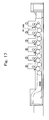
- the one shown in Fig. 17 is called an interdeck system, which is an apparatus for drying the printed surface of a sheet of paper (hereinafter referred to as a sheet) immediately after being printed between an impression cylinder and a blanket cylinder by a UV lamp provided at a position opposing the impression cylinder of each of six-color printing units each comprising a plate cylinder, the blanket cylinder and the impression cylinder.
- a sheet a sheet of paper
- a UV lamp provided at a position opposing the impression cylinder of each of six-color printing units each comprising a plate cylinder, the blanket cylinder and the impression cylinder.
- a drying unit system which is an apparatus having a drying unit including a transport cylinder and a UV lamp provided at a position opposing the transport cylinder, the drying unit being dedicated to drying and provided separately from the six-color printing units, and the apparatus being designed to dry the printed surface of a sheet printed between the impression cylinder and the blanket cylinder of each of the first printing unit to the fourth printing unit by the UV lamp of the drying unit provided downstream, in the sheet transport direction, of the first printing unit to the fourth printing unit.
- JP-A-2004-99314 is an example of a related art document showing the above type of drying apparatus.
- the overall length of the printing press can be shortened, and the printed surface of the sheet can be printed and then immediately dried by the UV lamp, in comparison with a printing press as shown in Fig. 18 .
- the disadvantage arises that ultraviolet radiation thrown onto the printed surface (surface of the impression cylinder) is reflected to cure UV ink (ultraviolet curing ink) on the blanket.
- the drying apparatus is the drying unit dedicated to drying, and is thus free from the disadvantage of curing the UV ink on the blanket.
- the disadvantage is caused that compared with the printing press shown in Fig. 17 , the overall length of the printing press is increased, and the printed surface of the sheet printed by any of the first printing unit to the fourth printing unit is scratched by a transfer cylinder provided between the impression cylinders before the UV ink is dried. That is, the UV ink is peeled and deposited on the circumferential surface of the transfer cylinder, and this peeled UV ink smears the printed surface of the succeeding sheet. Such a problem occurs similarly in a coating device which supplies UV varnish to a sheet.
- the present invention has been conceived in light of the above-described circumstances. It is an object of the invention to provide a drying apparatus for a sheet, which can shorten the overall length of a machine to achieve cost reduction, prevents adverse influence due to the reflection of light thrown, and has a high drying ability.
- a first aspect in accordance with the present invention is a drying apparatus for a sheet, including drying means which opposes a printed surface or a coated surface of the sheet printed by a printing section or coated by a coating section to dry the printed surface or the coated surface of the sheet, comprising: a transport cylinder having sheet holding means for receiving the sheet immediately after being printed by the printing section or coated by the coating section, wherein the drying means is disposed within the transport cylinder in such a manner as to oppose the printed surface or the coated surface of the sheet held by the sheet holding means of the transport cylinder.
- the sheet may be guided by a plurality of sheet guide members provided with spacing in an axial direction of the transport cylinder, an outer peripheral surface of each of the sheet guide members being supported by the transport cylinder while extending in a rotating direction of the transport cylinder.
- the drying apparatus for a sheet may further comprise air means for bringing the sheet along the outer peripheral surface of each of the sheet guide members.
- the air means may be air blowing means, and the air blowing means may oppose each of the sheet guide members and eject air toward each of the sheet guide members.
- a plurality of the air blowing means may be provided to be arranged along a locus of movement of the sheet holding means in accordance with rotation of the transport cylinder.
- the sheet guide members may be supported to be movable in the axial direction of the transport cylinder.
- the drying means may be supported to be movable in an axial direction of the transport cylinder.
- the drying means can be detached laterally of the transport cylinder.
- the transport cylinder may be rotatably supported by a frame, and the drying means may be supported not to be rotatable with respect to the frame.
- the transport cylinder may comprise a pair of hollow shaft members rotatably supported by a pair of the frames, a connecting member supported between the pair of hollow shaft members and constituting the sheet holding means, and drive transmission means provided on at least one of the pair of shaft members for transmitting drive to the transport cylinder, and the drying means may be provided between the pair of shaft members, and opposing the printed surface or the coated surface of the sheet held by the sheet holding means of the transport cylinder to dry the printed surface or the coated surface of the sheet.
- the drying means may be a UV lamp for drying the printed surface or the coated surface of the sheet, and a cover having an opening on a side of the UV lamp opposing the printed surface or the coated surface of the sheet may be provided.
- the drying apparatus for a sheet may further comprise: a first guide member fixed to a frame side and extending along the axial direction of the transport cylinder; a second guide member fixed to the drying means, which dries the printed surface or the coated surface of the sheet, and extending along the axial direction of the transport cylinder; and a third guide member engaging the first guide member and the second guide member, extending along the axial direction of the transport cylinder, supported by the first guide member, and supporting the second guide member.
- the drying apparatus for a sheet may further comprise air ejection means provided along a locus of movement of the sheet holding means in accordance with rotation of the transport cylinder, and adapted to eject air toward opposite end portions, in an axial direction of the transport cylinder, of the sheet transported by the transport cylinder.
- the drying apparatus for a sheet may further comprise heat release means for releasing heat generated within the transport cylinder to an outside.
- the transport cylinder may be rotatably supported by a frame, and the drying means may be supported to be rotatable, where necessary, with respect to the frame independently of rotation of the transport cylinder.
- the drying apparatus for a sheet may further comprise interference preventionmeans whichmoves the drying means from a position in proximity to the sheet to a position spaced from the sheet in a radial direction of the transport cylinder when the drying means opposes the sheet holding means of the transport cylinder, thereby preventing interference of the drying means with the sheet holding means.
- the drying apparatus for a sheet may further comprise: a sheet guide member opposing the transport cylinder and provided along a locus of movement of the sheet holding means of the transport cylinder to guide the sheet transported by the transport cylinder; and sheet moving means for bringing the sheet transported by the transport cylinder into contact with an outer peripheral surface of the sheet guide member.
- the sheet moving means may be air blowing means provided within the transport cylinder, and the air blowing means may oppose the sheet guide member and eject air toward the sheet guide member, thereby bringing the sheet held by the sheet holding means into contact with the outer peripheral surface of the sheet guide member.
- the drying means is accommodated within the transport cylinder.
- Fig. 1 is a general schematic configurational drawing of a printing press showing Embodiment 1 of the present invention.
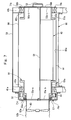
- Fig. 2 is a side sectional view of a transfer cylinder in the printing press.
- Fig. 3 is a front sectional view of the transfer cylinder.
- Fig. 4 is a plan view of the transfer cylinder.
- Figs. 5 (a), 5 (b) and 5 (b) are explanation drawings of a slide rail.
- a feeder board 11 for feeding sheets of paper (simply called sheets) on a pile (not shown) to a printing section 20 one by one is provided in a feeder 10.
- a swing arm shaft pregripper 12 for passing the sheet on to an impression cylinder 21a of a first offset printing unit 20A of the printing section 20 via an intermediate cylinder 13 is provided at the leading end of the feeder board 11.
- a blanket cylinder 22a is in contact with the impression cylinder 21a of the first offset printing unit 20A at a portion downstream of the intermediate cylinder 13 in the rotating direction of the impression cylinder 21a.
- a plate cylinder 23a is in contact with the blanket cylinder 22a at a portion upstream of the impression cylinder 21a in the rotating direction of the blanket cylinder 22a.
- An ink supply device and a dampening device are provided on a side of the plate cylinder 23a upstream of the blanket cylinder 22a in the rotating direction of the plate cylinder 23a.
- a surface of the impression cylinder 21a downstream of the blanket cylinder 22a in the rotating direction of the impression cylinder 21a in the first offset printing unit 20A is in contact with an impression cylinder 21b of a second offset printing unit 20B via a transfer cylinder (transport cylinder) 14.
- the second offset printing unit 20B is equipped with a blanket cylinder 22b, a plate cylinder 23b, an ink supply device, a dampening device, etc., as is the first offset printing unit 20A.
- a delivery cylinder (transport cylinder) 15 is in contact with a surface of the impression cylinder 21b downstream of the blanket cylinder 22b in the rotating direction of the impression cylinder 21b in the second offset printing unit 20B.
- the sheet printed by the first and second offset printing units 20A and 20B is transported from the delivery cylinder 15 to a delivery unit 30 by a delivery chain 31 passed over the delivery cylinder 15, whereafter the sheet is delivered onto a pile board (not shown).
- the transfer cylinder 14 and the delivery cylinder 15 are each composed of a skeleton cylinder, and have two UV lamps (drying means) 40 accommodated inside for irradiating the printed surface of the sheet with ultraviolet radiation to dry ultraviolet curing ink.
- the transfer cylinder 14 as shown in Figs. 2 to 4 , has left and right tubular flange portions (shaft members) 43a and 43b pivotably supported by left and right frames 41a and 41b via bearings 42a and 42b.
- each of the stays 45a and 45b is provided with a gripper device (sheet holding means) 46, in which a plurality of grippers 46b are mounted with predetermined spacing on a gripper bar 46a extending in the lateral direction.
- the gripper device 46 receives the sheet W (see Fig. 3 ) from the impression cylinder 21a of the first offset printing unit 20A, and passes the sheet W on to the impression cylinder 21b of the second offset printing unit 20B.
- a cam follower 46c for opening and closing of the grippers 46b can follow the cam surface of a cam (not shown) interlocked to the printing press.
- a plurality of arcuate rod-shaped guides (sheet guide members) 47 extending along the loci of rotation of the stays 45a, 45b (the outer peripheral portions of the transfer cylinder 14) are disposed with predetermined spacing in the cylinder axis direction in such a manner as to be arranged concentrically between the two stays 45a and 45b.
- the rod-shaped guides 47 have opposite end portions supported on support bars 48a and 48b installed between the left and right tubular flange portions 43a and 43b.
- the rod-shaped guides 47 can be moved on the support bars 48a, 48b in the cylinder axis direction, by loosening bolts 48c, in accordance with the imposition of printing products, namely, so that the mounting positions of the rod-shaped guides 47 can be adjusted in correspondence with the margin of the printed surface.
- fans 49 for blowing air i.e. , air means or air blowing means
- These fans 49 in combination with the rod-shaped guides 47 constitute a guide device for the sheet W.
- a support plate 50 is installed between the left and right frames 41a and 41b to support the many fans 49.
- reference numeral 49A denotes an air blowing nozzle.
- a support case 51 having a channel-shaped cross-section is transversely installed, with its open portion directed downward, within the transfer cylinder 14 in such a manner as to penetrate the space between the left and right tubular flange portions 43a and 43b.
- the support case 51 has opposite end portions secured to end plates 55a and 55b.
- the left end plate 55a permits the rotation of the tubular flange portion 43a via an oil seal 57, and is fixed to the frame 41a via a tubular bracket 56.
- the right end plate 55b is directly fixed to the frame 41b, and is provided with a lid member 58 for opening and closing an opening portion 55b-a through which the UV lamp 40 is entered and removed.
- the two UV lamps 40 are supported within the support case 51 to be slidable in the axial direction of the transfer cylinder 14 via slide rails 52. These UV lamps 40 are mounted to be pointed downward so as to be capable of throwing ultraviolet radiation downwardly. Moreover, these UV lamps 40 can be withdrawn, where necessary, rightward in Fig. 3 (i.e. , to the work side) to the outside of the printing press via handles 53.
- light blocking plates 54 are annexed to both sides in the front-to-back direction of the support case 51 (i.e., a direction perpendicular to the axial direction of the transfer cylinder 14) to prevent leakage of ultraviolet radiation.
- the slide rail 52 as shown in Figs. 5(a) to 5(c) , comprises a movable rail (second guide member) 52a secured to the UV lamp 40, a stationary rail (first guide member) 52b secured to the support case 51, an intermediate rail (third guide member) 52c slidably fitted to both of the movable rail 52a and the stationary rail 52b.
- the slide rail 52 can extend out by an amount which is the sum of the lengths of the movable rail 52a and most of the intermediate rail 52c.
- reference numeral 59 denotes a step of the printing press.
- the UV lamp (drying means) 40 in the delivery cylinder 15 is provided in the same configuration as that in the transfer cylinder 14. Thus, its explanation will be omitted here by reference to the above descriptions.
- the sheets W dispatched, one by one, from the feeder 10 onto the feeder board 11 are passed by the swing arm shaft pregripper 12 on to the impression cylinder 21a of the first offset printing unit 20A of the printing section 20 via the intermediate cylinder 13.
- the plate cylinder 23a is supplied with ink from the ink supply device of the first offset printing unit 20A, and dampening water from the dampener of the first offset printing unit 20A.
- the blanket cylinder 22a supplied with the ink from the plate cylinder 23a and the sheet W held on the impression cylinder 21a are brought into contact to print the sheet W in a first color.
- the sheet W is passed on to the impression cylinder 21b of the second offset printing unit 20B via the transfer cylinder 14 to print the sheet W in a second color in the second offset printing unit 20B, as in the first offset printing unit 20A. Then, the sheet W is passed on to the delivery chain 31 via the delivery cylinder 15 for transport to the delivery unit 30, and is then delivered.
- the ink of the first color printed in the first offset printing unit 20A is dried by the two UV lamps 40 accommodated inside the transfer cylinder 14, while the ink of the second color printed in the second offset printing unit 20B is similarly dried by the two UV lamps 40 accommodated inside the delivery cylinder 15.
- the sheet W having a front end portion gripped by the grippers 46b of the gripper device 46 is blown upward by air blown out of the many fans 49, and transported so as to be guided by the plurality of rod-shaped guides 47.
- the sheet W has the printed surface irradiated with ultraviolet radiation applied downward from the UV lamps 40, whereby the ultraviolet curing inks are dried.
- the two UV lamps 40 are accommodated within the transfer cylinder 14 and the delivery cylinder 15.
- the drying ability can be enhanced in comparison with the single UV lamp 40, and there is no need to provide the dedicated unit as stated earlier.
- an intermediate position of drying can be set at an arbitrary position in the printing section 20 or the like.
- the overall length of the machine can be shortened, and cost reduction can be achieved.
- the two UV lamps 40 throw ultraviolet rays downward, and the regions above them and lateral to them are covered with the support case 51 and the light blocking plates 54.
- ultraviolet radiation does not leak to a region in the vicinity of the site of contact (printing) between the impression cylinder 21a or 21b and the blanket cylinder 22a or 22b, which is a region located in a direction reverse to the direction of irradiation by the UV lamps 40.
- This avoids the disadvantage of curing the ultraviolet curing inks on the blankets of the blanket cylinders 22a, 22b.
- the two UV lamps 40 are used in a fixed state while the printing press is in operation. Thus, an energy saving can be realized, resulting in cost reduction.
- the sheet W is blown upward by air blown out of the many fans 49, and transported so as to be guided by the plurality of rod-shaped guides 47.
- the printed surface can be brought as close as possible to the UV lamps 40, leading to the advantage that the drying ability is even more enhanced.
- the UV lamp 40 as a whole can be withdrawn, where necessary, to the outside of the printing press to the right in Fig. 3 (i.e., the work side) via the slide rail 52.
- Fig. 6 is a side sectional view of a transfer cylinder showing Embodiment 2 of the present invention.
- Fig. 7 is a front sectional view of the transfer cylinder.
- Fig. 8 is a plan view of the transfer cylinder.
- Fig. 9 is a plan view of an air guide.
- Ventilations 55a-a, 55a-b and 55b-b, 55b-c are formed, respectively, in the end plates 55a and 55b annexed to the opposite endportions of the support case 51.
- Ducts 62a, 62b equipped with a fan (heat release means) 63 are connected to the left end plate 55a in Fig. 7 , while a filter 58A furnished with a handle 53 is annexed to the right end plate 55b in Fig. 7 so as to close the ventilation holes 55b-b, 55b-c.
- reference numeral 64 denotes a light blocking cover provided directly below the step 59.
- the guide device composed of the rod-shaped guides 47 and the fans 49 in Embodiment 1 is replaced by an air guide (air means, air blowing means) 60 which is secured to the left and right frames 41a and 41b via brackets 61a and 61b, as shown in Fig. 9 .
- the air guide 60 has a guide plate 60a comprising an arcuate plate extending along the locus of rotation of the gripper device 46 of the transfer cylinder 14.
- the guide plate 60a has many air gushing holes 60ab formed therein.
- air gushing holes 60ab are bored such that air flows rightward and leftward symmetrically with respect to the center of the guide plate 60a (i.e., air flows in the sheet width direction of the sheet W) along the guide surface of the guide plate 60a.
- the air guide 60 has already been rendered known to the public by the document JP-A-2004-99314 filed by the applicant of the present application. Thus, its concrete configuration is to be referred to this document, and a relevant detailed description is omitted herein.
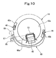
- Fig. 10 is a side sectional view of a transfer cylinder showing Embodiment 3 of the present invention.
- Fig. 11 is an explanation drawing of a swinging mechanism.
- Fig. 12 is a front sectional view of the transfer cylinder.
- levers 66a and 66b are secured to the opposite ends of a support bar 65 which penetrates the left and right frames 41a and 41b pivotably.
- Leading end portions of these levers 66a and 66b are secured to opposite end portions of the support case 51 which protrude from inside the transfer cylinder 14 through through-holes 55aa, 55bb of the end plates 55a, 55b.
- the UV lamp 40 is retreated inwardly within the transfer cylinder 14 at a desired time (see a dashed double-dotted line in Fig. 10 ) by a swinging mechanism (interference prevention means) so that the UV lamp 40 does not interfere with the gripper device 46 of the transfer cylinder 14, the swinging mechanism comprising an arm 67 secured to a left end portion of the support bar 65 in Fig. 11 , a cam follower 69 rotatably supported by the leading end of the arm 67, and a cam 68 secured to the side surface of the gear 44 and followed by the cam follower 69.
- a swinging mechanism interference prevention means
- return springs 70a, 70b are interposed between stoppers 71a, 71b secured to the support bar 65 and bearing members 72a, 72b secured to the frames 41a, 41b to return the UV lamp 40 from the position of retreat mentioned above (see a solid line in Fig. 10 ).
- the advantage that the UV lamp 40 can be brought as close as possible to the printed surface of the sheet W to render the drying ability even higher is obtained in addition to the same actions and effects as those in Embodiment 2.
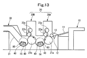
- Fig. 13 is a general schematic configurational drawing of a printing press showing Embodiment 4 of the present invention.
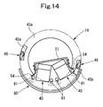
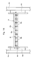
- Fig. 14 is a side sectional view of a transfer cylinder in the printing press.
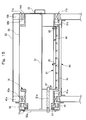
- Fig. 15 is a front sectional view of the transfer cylinder.
- Fig. 16 is a plan view of the transfer cylinder.
- a feeder board 11 for feeding sheets of paper (simply called sheets) on a pile (not shown) to a printing section 20 one by one is provided in a feeder 10.
- a swing arm shaft pregripper 12 for passing the sheet on to an impression cylinder 21a of a first offset printing unit 20A of the printing section 20 via an intermediate cylinder 13 is provided at the leading end of the feeder board 11.
- a blanket cylinder 22a is in contact with the impression cylinder 21a of the first offset printing unit 20A at a portion downstream of the intermediate cylinder 13 in the rotating direction of the impression cylinder 21a.
- a plate cylinder 23a is in contact with the blanket cylinder 22a at a portion upstream of the impression cylinder 21a in the rotating direction of the blanket cylinder 22a.
- An ink supply device and a dampening device are provided on a side of the plate cylinder 23a upstream of the blanket cylinder 22a in the rotating direction of the plate cylinder 23a.
- a surface of the impression cylinder 21a downstream of the blanket cylinder 22a in the rotating direction of the impression cylinder 21a in the first offset printing unit 20A is in contact with an impression cylinder 21b of a second offset printing unit 20B via a transfer cylinder (transport cylinder) 14.
- the second offset printing unit 20B is equipped with a blanket cylinder 22b, a plate cylinder 23b, an ink supply device, a dampening device, etc., as is the first offset printing unit 20A.
- a delivery cylinder (transport cylinder) 15 is in contact with a surface of the impression cylinder 21b downstream of the blanket cylinder 22b in the rotating direction of the impression cylinder 21b in the second offset printing unit 20B.
- the sheet printed by the first and second offset printing units 20A and 20B is transported from the delivery cylinder 15 to a delivery unit 30 by a delivery chain 31 passed over the delivery cylinder 15, whereafter the sheet is delivered onto a pile board (not shown).
- the transfer cylinder 14 and the delivery cylinder 15 are each composed of a skeleton cylinder, and have two UV lamps (drying means) 40 accommodated inside for irradiating the printed surface of the sheet with ultraviolet radiation to dry ultraviolet curing ink.
- the transfer cylinder 14 as shown in Figs. 14 to 16 , has left and right tubular flange portions (shaft members) 43a and 43b pivotably supported by left and right frames 41a and 41b via bearings 42a and 42b.
- each of the stays 45a and 45b is provided with a gripper device (sheet holding means) 46, in which a plurality of grippers 46b are mounted with predetermined spacing on a gripper bar 46a extending in the lateral direction.
- the gripper device 46 receives the sheet W (see Fig. 15 ) from the impression cylinder 21a of the first offset printing unit 20A, and passes the sheet W on to the impression cylinder 21b of the second offset printing unit 20B.
- a cam follower 46c for opening and closing of the grippers 46b can follow the cam surface of a cam (not shown) interlocked to the printing press.
- a paper guide (sheet guide member) 80 is secured to the left and right frames 41a and 41b via brackets 61a and 61b.
- the paper guide 80 comprises an arcuate plate extending along the locus of rotation of the gripper device 46 of the transfer cylinder 14, and has a size enough to cover a nearly lower half portion of the transfer cylinder 14.
- the paper guide 80 may be a plurality of rod-shaped guides disposed in the paper width direction, as in Embodiment 1.
- An air blowing nozzle pipe (air blowing means) 81 for pressing the sheet W onto the paper guide 80 by blowing is built in the transfer cylinder 14.
- Four of the air blowing nozzle pipes 81 are provided on front and rear side surfaces of UV lamps 40 (to be described later), while being supported by a suitable number of clamps 82, to eject air from multiple points in the paper width direction toward the paper guide 80.
- a left end side (in Fig. 15 ) of the air blowing nozzle pipe 81 has a flexible tube portion 81a suitably interposed halfway therethrough, is led outward through the left end plate 55a (in Fig. 15 ), and is connected to a pressurized air supply source (not shown).
- a support case 51 having a channel-shaped cross-section is transversely installed, with its open portion directed downward, within the transfer cylinder 14 in such a manner as to penetrate the space between the left and right tubular flange portions 43a and 43b.
- the support case 51 has opposite end portions secured to the end plates 55a and 55b.
- the left end plate 55a permits the rotation of the tubular flange portion 43a via an oil seal 57, and is fixed to the frame 41a via a tubular bracket 56.
- the right end plate 55b in Fig. 15 is directly fixed to the frame 41b.
- reference numeral 64 denotes a light blocking cover provided directly below the step 59.
- the UV lamp (drying means) 40 in the delivery cylinder 15 is provided in the same configuration as in the transfer cylinder 14. Thus, its explanation will be omitted here by reference to the above descriptions.
- the sheets W dispatched, one by one, from the feeder 10 onto the feeder board 11 are passed by the swing arm shaft pregripper 12 on to the impression cylinder 21a of the first offset printing unit 20A of the printing section 20 via the intermediate cylinder 13.
- the plate cylinder 23a is supplied with ink from the ink supply device of the first offset printing unit 20A, and dampening water from the dampener of the first offset printing unit 20A.
- the blanket cylinder 22a supplied with the ink from the plate cylinder 23a and the sheet W held on the impression cylinder 21a are brought into contact to print the sheet W in a first color.
- the sheet W is passed on to the impression cylinder 21b of the second offset printing unit 20B via the transfer cylinder 14 to print the sheet W in a second color in the second offset printing unit 20B, as in the first offset printing unit 20A. Then, the sheet W is passed on to the delivery chain 31 via the delivery cylinder 15 for transport to the delivery unit 30, and is then delivered.
- the ink of the first color printed in the first offset printing unit 20A is dried by the two UV lamps 40 accommodated inside the transfer cylinder 14, while the ink of the second color printed in the second offset printing unit 20B is similarly dried by the two UV lamps 40 accommodated inside the delivery cylinder 15.
- the sheet W having a front end portion gripped by the grippers 46b of the gripper device 46 is transported so as to be pressed against the paper guide 80 by air blown out of the air blowing nozzle pipes 81 at their multiple points.
- the sheet W has the printed surface irradiated with ultraviolet radiation applied downward from the UV lamps 40, whereby the ultraviolet curing inks are dried.
- the two UV lamps 40 are accommodated within the transfer cylinder 14 and the delivery cylinder 15.
- the drying ability can be enhanced in comparison with the single UV lamp 40, and there is no need to provide the dedicated unit as stated earlier.
- the intermediate position of drying can be set at an arbitrary position in the printing section 20 or the like.
- the overall length of the machine can be shortened, and cost reduction can be achieved.
- the two UV lamps 40 throw ultraviolet rays downward, and the regions above them and lateral to them are covered with the support case 51 and the light blocking cover 64.
- ultraviolet radiation does not leak to a region in the vicinity of the site of contact (printing) between the impression cylinder 21a or 21b and the blanket cylinder 22a or 22b, which is a region located in a direction reverse to the direction of irradiation by the UV lamps 40.
- This avoids the disadvantage of curing the ultraviolet curing inks on the blankets of the blanket cylinders 22a, 22b.
- the two UV lamps 40 are used in a fixed state while the printing press is in operation. Thus, an energy saving can be realized, resulting in cost reduction.
- the advantage is obtained that during maintenance of the UV lamps 40, maintenance of the air blowing nozzle pipes 81 can also be performed at the same time.
- the present invention has been described by the above embodiments, it is to be understood that the invention is not limited to these embodiments, but may be varied in many other ways.
- the diameters of the transfer cylinder 14 and the delivery cylinder 15 can be changed, and the number of the UV lamps 4 0 can be changed.
- the fans 49 which are the air blowing means as the air means, are provided below the transfer cylinder 14, and air blown out of the fans 49 enables the sheet W to be guided by the rod-shaped guides 47 supported by the transfer cylinder 14.
- air suction means as the air means may be provided within the transfer cylinder 14, and air sucked into the air suction means may enable the sheet W to be guided by the rod-shaped guides 47 supported by the transfer cylinder 14.
- Embodiment 2 heat is released to the outside by sucking air from inside the transfer cylinder 14 by means of the fan 63 as the heat release means.
- heat maybe released to the outside by ejecting air.
- the present invention is not limited to the printing press, but can also be applied to a coating device which has a drying apparatus for drying varnish supplied to a sheet.
Abstract
Description
- This invention relates to a drying apparatus for a sheet in a printing press or a coating device which has the drying apparatus for drying a liquid, such as ink or varnish, supplied to the sheet.
- As this type of drying apparatus, those shown in
Figs. 17 and18 , for example, are present. - The one shown in
Fig. 17 is called an interdeck system, which is an apparatus for drying the printed surface of a sheet of paper (hereinafter referred to as a sheet) immediately after being printed between an impression cylinder and a blanket cylinder by a UV lamp provided at a position opposing the impression cylinder of each of six-color printing units each comprising a plate cylinder, the blanket cylinder and the impression cylinder. The one shown inFig. 18 is called a drying unit system, which is an apparatus having a drying unit including a transport cylinder and a UV lamp provided at a position opposing the transport cylinder, the drying unit being dedicated to drying and provided separately from the six-color printing units, and the apparatus being designed to dry the printed surface of a sheet printed between the impression cylinder and the blanket cylinder of each of the first printing unit to the fourth printing unit by the UV lamp of the drying unit provided downstream, in the sheet transport direction, of the first printing unit to the fourth printing unit. -
JP-A-2004-99314 - With a printing press as shown in
Fig. 17 , the overall length of the printing press can be shortened, and the printed surface of the sheet can be printed and then immediately dried by the UV lamp, in comparison with a printing press as shown inFig. 18 . However, the disadvantage arises that ultraviolet radiation thrown onto the printed surface (surface of the impression cylinder) is reflected to cure UV ink (ultraviolet curing ink) on the blanket. - In the printing press shown in
Fig. 18 , on the other hand, the drying apparatus is the drying unit dedicated to drying, and is thus free from the disadvantage of curing the UV ink on the blanket. However, the disadvantage is caused that compared with the printing press shown inFig. 17 , the overall length of the printing press is increased, and the printed surface of the sheet printed by any of the first printing unit to the fourth printing unit is scratched by a transfer cylinder provided between the impression cylinders before the UV ink is dried. That is, the UV ink is peeled and deposited on the circumferential surface of the transfer cylinder, and this peeled UV ink smears the printed surface of the succeeding sheet. Such a problem occurs similarly in a coating device which supplies UV varnish to a sheet. - The present invention has been conceived in light of the above-described circumstances. It is an object of the invention to provide a drying apparatus for a sheet, which can shorten the overall length of a machine to achieve cost reduction, prevents adverse influence due to the reflection of light thrown, and has a high drying ability.
- A first aspect in accordance with the present invention is a drying apparatus for a sheet, including drying means which opposes a printed surface or a coated surface of the sheet printed by a printing section or coated by a coating section to dry the printed surface or the coated surface of the sheet, comprising: a transport cylinder having sheet holding means for receiving the sheet immediately after being printed by the printing section or coated by the coating section, wherein the drying means is disposed within the transport cylinder in such a manner as to oppose the printed surface or the coated surface of the sheet held by the sheet holding means of the transport cylinder.
- According to a second aspect of the present invention, the sheet may be guided by a plurality of sheet guide members provided with spacing in an axial direction of the transport cylinder, an outer peripheral surface of each of the sheet guide members being supported by the transport cylinder while extending in a rotating direction of the transport cylinder.
- According to a third aspect of the present invention, the drying apparatus for a sheet may further comprise air means for bringing the sheet along the outer peripheral surface of each of the sheet guide members.
- According to a fourth aspect of the present invention, the air means may be air blowing means, and the air blowing means may oppose each of the sheet guide members and eject air toward each of the sheet guide members.
- According to a fifth aspect of the present invention, a plurality of the air blowing means may be provided to be arranged along a locus of movement of the sheet holding means in accordance with rotation of the transport cylinder.
- According to a sixth aspect of the present invention, the sheet guide members may be supported to be movable in the axial direction of the transport cylinder.
- According to a seventh aspect of the present invention, the drying means may be supported to be movable in an axial direction of the transport cylinder.
- According to an eighth aspect of the present invention, the drying means can be detached laterally of the transport cylinder.
- According to a ninth aspect of the present invention, the transport cylinder may be rotatably supported by a frame, and the drying means may be supported not to be rotatable with respect to the frame.
- According to a tenth aspect of the present invention, the transport cylinder may comprise a pair of hollow shaft members rotatably supported by a pair of the frames, a connecting member supported between the pair of hollow shaft members and constituting the sheet holding means, and drive transmission means provided on at least one of the pair of shaft members for transmitting drive to the transport cylinder, and the drying means may be provided between the pair of shaft members, and opposing the printed surface or the coated surface of the sheet held by the sheet holding means of the transport cylinder to dry the printed surface or the coated surface of the sheet.
- According to an eleventh aspect of the present invention, the drying means may be a UV lamp for drying the printed surface or the coated surface of the sheet, and a cover having an opening on a side of the UV lamp opposing the printed surface or the coated surface of the sheet may be provided.
- According to a twelfth aspect of the present invention, the drying apparatus for a sheet may further comprise: a first guide member fixed to a frame side and extending along the axial direction of the transport cylinder; a second guide member fixed to the drying means, which dries the printed surface or the coated surface of the sheet, and extending along the axial direction of the transport cylinder; and a third guide member engaging the first guide member and the second guide member, extending along the axial direction of the transport cylinder, supported by the first guide member, and supporting the second guide member.
- According to a thirteenth aspect of the present invention, the drying apparatus for a sheet may further comprise air ejection means provided along a locus of movement of the sheet holding means in accordance with rotation of the transport cylinder, and adapted to eject air toward opposite end portions, in an axial direction of the transport cylinder, of the sheet transported by the transport cylinder.
- According to a fourteenth aspect of the present invention, the drying apparatus for a sheet may further comprise heat release means for releasing heat generated within the transport cylinder to an outside.
- According to a fifteenth aspect of the present invention, the transport cylinder may be rotatably supported by a frame, and the drying means may be supported to be rotatable, where necessary, with respect to the frame independently of rotation of the transport cylinder.
- According to a sixteenth aspect of the present invention, the drying apparatus for a sheet may further comprise interference preventionmeans whichmoves the drying means from a position in proximity to the sheet to a position spaced from the sheet in a radial direction of the transport cylinder when the drying means opposes the sheet holding means of the transport cylinder, thereby preventing interference of the drying means with the sheet holding means.
- According to a seventeenth aspect of the present invention, the drying apparatus for a sheet may further comprise: a sheet guide member opposing the transport cylinder and provided along a locus of movement of the sheet holding means of the transport cylinder to guide the sheet transported by the transport cylinder; and sheet moving means for bringing the sheet transported by the transport cylinder into contact with an outer peripheral surface of the sheet guide member.
- According to an eighteenth aspect of the present invention, the sheet moving means may be air blowing means provided within the transport cylinder, and the air blowing means may oppose the sheet guide member and eject air toward the sheet guide member, thereby bringing the sheet held by the sheet holding means into contact with the outer peripheral surface of the sheet guide member.
- According to the drying apparatus for a sheet concerned with the present invention, the drying means is accommodated within the transport cylinder. Thus, it becomes possible to constitute a printing press or a coating device which has a high drying ability, can reduce leakage of light and exerts no adverse influence on anything other than the sheet, without increasing the overall length of the machine.
- The present invention will become more fully understood from the detailed description given hereinbelow and the accompanying drawings which are given by way of illustration only, and thus are not limitative of the present invention, and wherein:
-
Fig. 1 is a general schematic configurational drawing of a printing press showing Embodiment 1 of the present invention; -
Fig. 2 is a side sectional view of a transfer cylinder in the printing press; -
Fig. 3 is a front sectional view of the transfer cylinder; -
Fig. 4 is a plan view of the transfer cylinder; -
Figs. 5(a), 5(b) and 5(b) are explanation drawings of a slide rail; -
Fig. 6 is a side sectional view of a transfercylinder showing Embodiment 2 of the present invention; -
Fig. 7 is a front sectional view of the transfer cylinder; -
Fig. 8 is a plan view of the transfer cylinder; -
Fig. 9 is a plan view of an air guide; -
Fig. 10 is a side sectional view of a transfercylinder showing Embodiment 3 of the present invention; -
Fig. 11 is an explanation drawing of a swinging mechanism; -
Fig. 12 is a front sectional view of the transfer cylinder; -
Fig. 13 is a general schematic configurational drawing of a printingpress showing Embodiment 4 of the present invention; -
Fig. 14 is a side sectional view of a transfer cylinder in the printing press; -
Fig. 15 is a front sectional view of the transfer cylinder; -
Fig. 16 is a plan view of the transfer cylinder; -
Fig. 17 is an explanation drawing of a drying apparatus in a printing press as a conventional example; and -
Fig. 18 is an explanation drawing of a drying apparatus in a printing press as a different conventional example. - A drying apparatus for a sheet according to the present invention will be described in detail by embodiments with reference to the accompanying drawings.
-
Fig. 1 is a general schematic configurational drawing of a printing press showing Embodiment 1 of the present invention.Fig. 2 is a side sectional view of a transfer cylinder in the printing press.Fig. 3 is a front sectional view of the transfer cylinder.Fig. 4 is a plan view of the transfer cylinder.Figs. 5 (a), 5 (b) and 5 (b) are explanation drawings of a slide rail. - As shown in
Fig. 1 , afeeder board 11 for feeding sheets of paper (simply called sheets) on a pile (not shown) to aprinting section 20 one by one is provided in afeeder 10. A swingarm shaft pregripper 12 for passing the sheet on to animpression cylinder 21a of a first offsetprinting unit 20A of theprinting section 20 via anintermediate cylinder 13 is provided at the leading end of thefeeder board 11. - A
blanket cylinder 22a is in contact with theimpression cylinder 21a of the first offsetprinting unit 20A at a portion downstream of theintermediate cylinder 13 in the rotating direction of theimpression cylinder 21a. Aplate cylinder 23a is in contact with theblanket cylinder 22a at a portion upstream of theimpression cylinder 21a in the rotating direction of theblanket cylinder 22a. An ink supply device and a dampening device (not shown) are provided on a side of theplate cylinder 23a upstream of theblanket cylinder 22a in the rotating direction of theplate cylinder 23a. - A surface of the
impression cylinder 21a downstream of theblanket cylinder 22a in the rotating direction of theimpression cylinder 21a in the first offsetprinting unit 20A is in contact with animpression cylinder 21b of a second offsetprinting unit 20B via a transfer cylinder (transport cylinder) 14. The second offsetprinting unit 20B is equipped with ablanket cylinder 22b, aplate cylinder 23b, an ink supply device, a dampening device, etc., as is the first offsetprinting unit 20A. - A delivery cylinder (transport cylinder) 15 is in contact with a surface of the
impression cylinder 21b downstream of theblanket cylinder 22b in the rotating direction of theimpression cylinder 21b in the second offsetprinting unit 20B. The sheet printed by the first and second offsetprinting units delivery cylinder 15 to adelivery unit 30 by adelivery chain 31 passed over thedelivery cylinder 15, whereafter the sheet is delivered onto a pile board (not shown). - The
transfer cylinder 14 and thedelivery cylinder 15 are each composed of a skeleton cylinder, and have two UV lamps (drying means) 40 accommodated inside for irradiating the printed surface of the sheet with ultraviolet radiation to dry ultraviolet curing ink. - In detail, the
transfer cylinder 14, as shown inFigs. 2 to 4 , has left and right tubular flange portions (shaft members) 43a and 43b pivotably supported by left andright frames bearings tubular flange portion 43a located on the drive side (left-hand side inFig. 3 ) meshes with a gear train (not shown) so that thetransfer cylinder 14 is rotationally driven in synchronism with the respective cylinders of the printing press. - Between the left and right
tubular flange portions tubular flange portions stays grippers 46b are mounted with predetermined spacing on agripper bar 46a extending in the lateral direction. By the opening and closing of thesegrippers 46b, thegripper device 46 receives the sheet W (seeFig. 3 ) from theimpression cylinder 21a of the first offsetprinting unit 20A, and passes the sheet W on to theimpression cylinder 21b of the second offsetprinting unit 20B. InFig. 4 , acam follower 46c for opening and closing of thegrippers 46b can follow the cam surface of a cam (not shown) interlocked to the printing press. - A plurality of arcuate rod-shaped guides (sheet guide members) 47 extending along the loci of rotation of the
stays stays guides 47 have opposite end portions supported onsupport bars tubular flange portions guides 47 can be moved on the support bars 48a, 48b in the cylinder axis direction, by looseningbolts 48c, in accordance with the imposition of printing products, namely, so that the mounting positions of the rod-shapedguides 47 can be adjusted in correspondence with the margin of the printed surface. -
Many fans 49 for blowing air (i.e. , air means or air blowing means) so that the sheet W is guided by the rod-shapedguides 47 are disposed along a lower half of thetransfer cylinder 14 in the circumferential direction and the cylinder axis direction. Thesefans 49 in combination with the rod-shapedguides 47 constitute a guide device for the sheet W. InFigs. 2 and3 , asupport plate 50 is installed between the left andright frames many fans 49. InFig. 2 ,reference numeral 49A denotes an air blowing nozzle. - A
support case 51 having a channel-shaped cross-section is transversely installed, with its open portion directed downward, within thetransfer cylinder 14 in such a manner as to penetrate the space between the left and righttubular flange portions support case 51 has opposite end portions secured toend plates left end plate 55a permits the rotation of thetubular flange portion 43a via anoil seal 57, and is fixed to theframe 41a via atubular bracket 56. On the other hand, theright end plate 55b is directly fixed to theframe 41b, and is provided with alid member 58 for opening and closing anopening portion 55b-a through which theUV lamp 40 is entered and removed. - The two
UV lamps 40 are supported within thesupport case 51 to be slidable in the axial direction of thetransfer cylinder 14 via slide rails 52. TheseUV lamps 40 are mounted to be pointed downward so as to be capable of throwing ultraviolet radiation downwardly. Moreover, theseUV lamps 40 can be withdrawn, where necessary, rightward inFig. 3 (i.e. , to the work side) to the outside of the printing press via handles 53. InFig. 2 ,light blocking plates 54 are annexed to both sides in the front-to-back direction of the support case 51 (i.e., a direction perpendicular to the axial direction of the transfer cylinder 14) to prevent leakage of ultraviolet radiation. - The
slide rail 52, as shown inFigs. 5(a) to 5(c) , comprises a movable rail (second guide member) 52a secured to theUV lamp 40, a stationary rail (first guide member) 52b secured to thesupport case 51, an intermediate rail (third guide member) 52c slidably fitted to both of themovable rail 52a and thestationary rail 52b. When maximally extended, theslide rail 52 can extend out by an amount which is the sum of the lengths of themovable rail 52a and most of theintermediate rail 52c. - In
Fig. 3 ,reference numeral 59 denotes a step of the printing press. The UV lamp (drying means) 40 in thedelivery cylinder 15 is provided in the same configuration as that in thetransfer cylinder 14. Thus, its explanation will be omitted here by reference to the above descriptions. - The actions of the printing press according to the present embodiment constituted as above will be described below.
- The sheets W dispatched, one by one, from the
feeder 10 onto thefeeder board 11 are passed by the swingarm shaft pregripper 12 on to theimpression cylinder 21a of the first offsetprinting unit 20A of theprinting section 20 via theintermediate cylinder 13. Separately, theplate cylinder 23a is supplied with ink from the ink supply device of the first offsetprinting unit 20A, and dampening water from the dampener of the first offsetprinting unit 20A. Theblanket cylinder 22a supplied with the ink from theplate cylinder 23a and the sheet W held on theimpression cylinder 21a are brought into contact to print the sheet W in a first color. - Then, the sheet W is passed on to the
impression cylinder 21b of the second offsetprinting unit 20B via thetransfer cylinder 14 to print the sheet W in a second color in the second offsetprinting unit 20B, as in the first offsetprinting unit 20A. Then, the sheet W is passed on to thedelivery chain 31 via thedelivery cylinder 15 for transport to thedelivery unit 30, and is then delivered. - During this process, the ink of the first color printed in the first offset
printing unit 20A is dried by the twoUV lamps 40 accommodated inside thetransfer cylinder 14, while the ink of the second color printed in the second offsetprinting unit 20B is similarly dried by the twoUV lamps 40 accommodated inside thedelivery cylinder 15. - That is, with the
transfer cylinder 14 and thedelivery cylinder 15, the sheet W having a front end portion gripped by thegrippers 46b of thegripper device 46 is blown upward by air blown out of themany fans 49, and transported so as to be guided by the plurality of rod-shaped guides 47. On this occasion, the sheet W has the printed surface irradiated with ultraviolet radiation applied downward from theUV lamps 40, whereby the ultraviolet curing inks are dried. - In this manner, according to the present embodiment, the two
UV lamps 40 are accommodated within thetransfer cylinder 14 and thedelivery cylinder 15. Thus, the drying ability can be enhanced in comparison with thesingle UV lamp 40, and there is no need to provide the dedicated unit as stated earlier. Hence, an intermediate position of drying can be set at an arbitrary position in theprinting section 20 or the like. Furthermore, the overall length of the machine can be shortened, and cost reduction can be achieved. - According to the present embodiment, the two
UV lamps 40 throw ultraviolet rays downward, and the regions above them and lateral to them are covered with thesupport case 51 and thelight blocking plates 54. Thus, ultraviolet radiation does not leak to a region in the vicinity of the site of contact (printing) between theimpression cylinder blanket cylinder UV lamps 40. This avoids the disadvantage of curing the ultraviolet curing inks on the blankets of theblanket cylinders UV lamps 40 are used in a fixed state while the printing press is in operation. Thus, an energy saving can be realized, resulting in cost reduction. - According to the present embodiment, the sheet W is blown upward by air blown out of the
many fans 49, and transported so as to be guided by the plurality of rod-shaped guides 47. Thus, the printed surface can be brought as close as possible to theUV lamps 40, leading to the advantage that the drying ability is even more enhanced. - According to the present embodiment, moreover, the
UV lamp 40 as a whole can be withdrawn, where necessary, to the outside of the printing press to the right inFig. 3 (i.e., the work side) via theslide rail 52. This confers the advantage that maintenance of theUV lamp 40 can be performed easily. -
Fig. 6 is a side sectional view of a transfercylinder showing Embodiment 2 of the present invention.Fig. 7 is a front sectional view of the transfer cylinder.Fig. 8 is a plan view of the transfer cylinder.Fig. 9 is a plan view of an air guide. - In Embodiment 1,
ventilation holes 55a-a, 55a-b and 55b-b, 55b-c are formed, respectively, in theend plates support case 51.Ducts left end plate 55a inFig. 7 , while afilter 58A furnished with ahandle 53 is annexed to theright end plate 55b inFig. 7 so as to close the ventilation holes 55b-b, 55b-c. In this configuration, air which has been taken in through the ventilation holes 55b-b, 55b-c is sucked into theducts ventilation holes 55a-a, 55a-b by thefan 63 to air-cool theUV lamps 40. - During maintenance of the
UV lamp 40,bolts 71a for fixing theend plate 55a to thetubular bracket 56, andbolts 71b for fixing theend plate 55b to theframe 41b are detached, and thehandle 53 integrally attached to theend plate 55b via thefilter 58A is rotated to invert theUV lamp 40 together with thesupport case 51 so that a maintenance operation can be performed from above thestep 59. InFig. 7 ,reference numeral 64 denotes a light blocking cover provided directly below thestep 59. - Further, the guide device composed of the rod-shaped
guides 47 and thefans 49 in Embodiment 1 is replaced by an air guide (air means, air blowing means) 60 which is secured to the left andright frames brackets Fig. 9 . Theair guide 60 has aguide plate 60a comprising an arcuate plate extending along the locus of rotation of thegripper device 46 of thetransfer cylinder 14. Theguide plate 60a has many air gushing holes 60ab formed therein. These air gushing holes 60ab are bored such that air flows rightward and leftward symmetrically with respect to the center of theguide plate 60a (i.e., air flows in the sheet width direction of the sheet W) along the guide surface of theguide plate 60a. Theair guide 60 has already been rendered known to the public by the documentJP-A-2004-99314 - Other features are the same as those in Embodiment 1. Thus, the same members as those in
Figs. 2 to 4 will be assigned same reference numerals as those indicated in these drawings, and duplicate explanations are omitted. - In the present embodiment as well, the same actions and effects as those in Embodiment 1 are obtained.
-
Fig. 10 is a side sectional view of a transfercylinder showing Embodiment 3 of the present invention.Fig. 11 is an explanation drawing of a swinging mechanism.Fig. 12 is a front sectional view of the transfer cylinder. - To support the
UV lamp 40 inEmbodiment 2 swingably, proximal end portions oflevers support bar 65 which penetrates the left andright frames levers support case 51 which protrude from inside thetransfer cylinder 14 through through-holes 55aa, 55bb of theend plates - The
UV lamp 40 is retreated inwardly within thetransfer cylinder 14 at a desired time (see a dashed double-dotted line inFig. 10 ) by a swinging mechanism (interference prevention means) so that theUV lamp 40 does not interfere with thegripper device 46 of thetransfer cylinder 14, the swinging mechanism comprising anarm 67 secured to a left end portion of thesupport bar 65 inFig. 11 , acam follower 69 rotatably supported by the leading end of thearm 67, and acam 68 secured to the side surface of thegear 44 and followed by thecam follower 69. InFig. 11 , return springs 70a, 70b are interposed betweenstoppers support bar 65 andbearing members frames UV lamp 40 from the position of retreat mentioned above (see a solid line inFig. 10 ). - Other features are the same as those in
Embodiment 2. Thus,Figs. 6 to 9 are to be referred to for these features, and detailed explanations are omitted here. - In the present embodiment as well, the advantage that the
UV lamp 40 can be brought as close as possible to the printed surface of the sheet W to render the drying ability even higher is obtained in addition to the same actions and effects as those inEmbodiment 2. -
Fig. 13 is a general schematic configurational drawing of a printingpress showing Embodiment 4 of the present invention.Fig. 14 is a side sectional view of a transfer cylinder in the printing press.Fig. 15 is a front sectional view of the transfer cylinder.Fig. 16 is a plan view of the transfer cylinder. - As shown in
Fig. 13 , afeeder board 11 for feeding sheets of paper (simply called sheets) on a pile (not shown) to aprinting section 20 one by one is provided in afeeder 10. A swingarm shaft pregripper 12 for passing the sheet on to animpression cylinder 21a of a first offsetprinting unit 20A of theprinting section 20 via anintermediate cylinder 13 is provided at the leading end of thefeeder board 11. - A
blanket cylinder 22a is in contact with theimpression cylinder 21a of the first offsetprinting unit 20A at a portion downstream of theintermediate cylinder 13 in the rotating direction of theimpression cylinder 21a. Aplate cylinder 23a is in contact with theblanket cylinder 22a at a portion upstream of theimpression cylinder 21a in the rotating direction of theblanket cylinder 22a. An ink supply device and a dampening device (not shown) are provided on a side of theplate cylinder 23a upstream of theblanket cylinder 22a in the rotating direction of theplate cylinder 23a. - A surface of the
impression cylinder 21a downstream of theblanket cylinder 22a in the rotating direction of theimpression cylinder 21a in the first offsetprinting unit 20A is in contact with animpression cylinder 21b of a second offsetprinting unit 20B via a transfer cylinder (transport cylinder) 14. The second offsetprinting unit 20B is equipped with ablanket cylinder 22b, aplate cylinder 23b, an ink supply device, a dampening device, etc., as is the first offsetprinting unit 20A. - A delivery cylinder (transport cylinder) 15 is in contact with a surface of the
impression cylinder 21b downstream of theblanket cylinder 22b in the rotating direction of theimpression cylinder 21b in the second offsetprinting unit 20B. The sheet printed by the first and second offsetprinting units delivery cylinder 15 to adelivery unit 30 by adelivery chain 31 passed over thedelivery cylinder 15, whereafter the sheet is delivered onto a pile board (not shown). - The
transfer cylinder 14 and thedelivery cylinder 15 are each composed of a skeleton cylinder, and have two UV lamps (drying means) 40 accommodated inside for irradiating the printed surface of the sheet with ultraviolet radiation to dry ultraviolet curing ink. - In detail, the
transfer cylinder 14, as shown inFigs. 14 to 16 , has left and right tubular flange portions (shaft members) 43a and 43b pivotably supported by left andright frames bearings tubular flange portion 43a located on the drive side (left-hand side inFig. 15 ) meshes with a gear train (not shown) so that thetransfer cylinder 14 is rotationally driven in synchronism with the respective cylinders of the printing press. - Between the left and right
tubular flange portions tubular flange portions 4 3 a and 43b. Each of thestays grippers 46b are mounted with predetermined spacing on agripper bar 46a extending in the lateral direction. By the opening and closing of thesegrippers 46b, thegripper device 46 receives the sheet W (seeFig. 15 ) from theimpression cylinder 21a of the first offsetprinting unit 20A, and passes the sheet W on to theimpression cylinder 21b of the second offsetprinting unit 20B. InFig. 16 , acam follower 46c for opening and closing of thegrippers 46b can follow the cam surface of a cam (not shown) interlocked to the printing press. - A paper guide (sheet guide member) 80 is secured to the left and
right frames brackets paper guide 80 comprises an arcuate plate extending along the locus of rotation of thegripper device 46 of thetransfer cylinder 14, and has a size enough to cover a nearly lower half portion of thetransfer cylinder 14. Thepaper guide 80 may be a plurality of rod-shaped guides disposed in the paper width direction, as in Embodiment 1. - An air blowing nozzle pipe (air blowing means) 81 for pressing the sheet W onto the
paper guide 80 by blowing is built in thetransfer cylinder 14. Four of the air blowingnozzle pipes 81 are provided on front and rear side surfaces of UV lamps 40 (to be described later), while being supported by a suitable number ofclamps 82, to eject air from multiple points in the paper width direction toward thepaper guide 80. A left end side (inFig. 15 ) of the air blowingnozzle pipe 81 has aflexible tube portion 81a suitably interposed halfway therethrough, is led outward through theleft end plate 55a (inFig. 15 ), and is connected to a pressurized air supply source (not shown). - A
support case 51 having a channel-shaped cross-section is transversely installed, with its open portion directed downward, within thetransfer cylinder 14 in such a manner as to penetrate the space between the left and righttubular flange portions support case 51 has opposite end portions secured to theend plates Fig. 15 , theleft end plate 55a permits the rotation of thetubular flange portion 43a via anoil seal 57, and is fixed to theframe 41a via atubular bracket 56. On the other hand, theright end plate 55b inFig. 15 is directly fixed to theframe 41b. - During maintenance of the
UV lamp 40,bolts 71a for fixing theend plate 55a to thetubular bracket 56, andbolts 71b for fixing theend plate 55b to theframe 41b are detached, and ahandle 53 integrally attached to theend plate 55b is rotated to invert theUV lamp 40 together with thesupport case 51 so that a maintenance operation can be performed from above astep 59. InFig. 15 ,reference numeral 64 denotes a light blocking cover provided directly below thestep 59. - The UV lamp (drying means) 40 in the
delivery cylinder 15 is provided in the same configuration as in thetransfer cylinder 14. Thus, its explanation will be omitted here by reference to the above descriptions. - The actions of the printing press according to the present embodiment constituted as above will be described below.
- The sheets W dispatched, one by one, from the
feeder 10 onto thefeeder board 11 are passed by the swingarm shaft pregripper 12 on to theimpression cylinder 21a of the first offsetprinting unit 20A of theprinting section 20 via theintermediate cylinder 13. Separately, theplate cylinder 23a is supplied with ink from the ink supply device of the first offsetprinting unit 20A, and dampening water from the dampener of the first offsetprinting unit 20A. Theblanket cylinder 22a supplied with the ink from theplate cylinder 23a and the sheet W held on theimpression cylinder 21a are brought into contact to print the sheet W in a first color. - Then, the sheet W is passed on to the
impression cylinder 21b of the second offsetprinting unit 20B via thetransfer cylinder 14 to print the sheet W in a second color in the second offsetprinting unit 20B, as in the first offsetprinting unit 20A. Then, the sheet W is passed on to thedelivery chain 31 via thedelivery cylinder 15 for transport to thedelivery unit 30, and is then delivered. - During this process, the ink of the first color printed in the first offset
printing unit 20A is dried by the twoUV lamps 40 accommodated inside thetransfer cylinder 14, while the ink of the second color printed in the second offsetprinting unit 20B is similarly dried by the twoUV lamps 40 accommodated inside thedelivery cylinder 15. - That is, with the
transfer cylinder 14 and thedelivery cylinder 15, the sheet W having a front end portion gripped by thegrippers 46b of thegripper device 46 is transported so as to be pressed against thepaper guide 80 by air blown out of the air blowingnozzle pipes 81 at their multiple points. On this occasion, the sheet W has the printed surface irradiated with ultraviolet radiation applied downward from theUV lamps 40, whereby the ultraviolet curing inks are dried. - In this manner, according to the present embodiment, the two
UV lamps 40 are accommodated within thetransfer cylinder 14 and thedelivery cylinder 15. Thus, the drying ability can be enhanced in comparison with thesingle UV lamp 40, and there is no need to provide the dedicated unit as stated earlier. Hence, the intermediate position of drying can be set at an arbitrary position in theprinting section 20 or the like. Furthermore, the overall length of the machine can be shortened, and cost reduction can be achieved. - According to the present embodiment, the two
UV lamps 40 throw ultraviolet rays downward, and the regions above them and lateral to them are covered with thesupport case 51 and thelight blocking cover 64. Thus, ultraviolet radiation does not leak to a region in the vicinity of the site of contact (printing) between theimpression cylinder blanket cylinder UV lamps 40. This avoids the disadvantage of curing the ultraviolet curing inks on the blankets of theblanket cylinders UV lamps 40 are used in a fixed state while the printing press is in operation. Thus, an energy saving can be realized, resulting in cost reduction. - According to the present embodiment, moreover, the advantage is obtained that during maintenance of the
UV lamps 40, maintenance of the air blowingnozzle pipes 81 can also be performed at the same time. - While the present invention has been described by the above embodiments, it is to be understood that the invention is not limited to these embodiments, but may be varied in many other ways. For example, the diameters of the
transfer cylinder 14 and thedelivery cylinder 15 can be changed, and the number of theUV lamps 4 0 can be changed. In Embodiment 1, thefans 49, which are the air blowing means as the air means, are provided below thetransfer cylinder 14, and air blown out of thefans 49 enables the sheet W to be guided by the rod-shapedguides 47 supported by thetransfer cylinder 14. However, air suction means as the air means may be provided within thetransfer cylinder 14, and air sucked into the air suction means may enable the sheet W to be guided by the rod-shapedguides 47 supported by thetransfer cylinder 14. Furthermore, inEmbodiment 2, heat is released to the outside by sucking air from inside thetransfer cylinder 14 by means of thefan 63 as the heat release means. However, heat maybe released to the outside by ejecting air. Besides, the present invention is not limited to the printing press, but can also be applied to a coating device which has a drying apparatus for drying varnish supplied to a sheet. Such variations are not to be regarded as a departure from the spirit and scope of the invention, and all such modifications as would be obvious to one skilled in the art are intended to be included within the scope of the appended claims.
Claims (18)
- A drying apparatus for a sheet, including drying means (40) which opposes a printed surface or a coated surface of the sheet (W) printed by a printing section (20) or coated by a coating section to dry the printed surface or the coated surface of the sheet, comprising:a transport cylinder (14, 15) having sheet holding means (46) for receiving the sheet immediately after being printed by the printing section or coated by the coating section,wherein the drying means is disposed within the transport cylinder in such a manner as to oppose the printed surface or the coated surface of the sheet held by the sheet holding means of the transport cylinder.
- The drying apparatus for a sheet according to claim 1, characterized in that
the sheet is guided by a plurality of sheet guide members (47) provided with spacing in an axial direction of the transport cylinder, an outer peripheral surface of each of the sheet guide members being supported by the transport cylinder while extending in a rotating direction of the transport cylinder. - The drying apparatus for a sheet according to claim 2, further comprising
air means (49, 60) for bringing the sheet along the outer peripheral surface of each of the sheet guide members. - The drying apparatus for a sheet according to claim 3, characterized in that
the air means is air blowing means (49), and
the air blowing means opposes each of the sheet guide members and ejects air toward each of the sheet guide members. - The drying apparatus for a sheet according to claim 4, characterized in that
a plurality of the air blowing means are provided to be arranged along a locus of movement of the sheet holding means in accordance with rotation of the transport cylinder. - The drying apparatus for a sheet according to claim 2, characterized in that
the sheet guide members (47) are supported to be movable in the axial direction of the transport cylinder. - The drying apparatus for a sheet according to claim 1, characterized in that
the drying means (40) is supported to be movable in an axial direction of the transport cylinder. - The drying apparatus for a sheet according to claim 7, characterized in that
the drying means can be detached laterally of the transport cylinder. - The drying apparatus for a sheet according to claim 1, characterized in that
the transport cylinder (14, 15) is rotatably supported by a frame (41a, 41b), and
the drying means is supported not to be rotatable with respect to the frame. - The drying apparatus for a sheet according to claim 1, characterized in that
the transport cylinder (14, 15) comprises a pair of hollow shaft members (43a, 43b) rotatably supported by a pair of frames, a connecting member (45a, 45b) supported between the pair of hollow shaft members and constituting the sheet holding means, and drive transmission means (44) provided on at least one of the pair of shaft members for transmitting drive to the transport cylinder, and
the drying means (40) is provided between the pair of shaft members, and opposing the printed surface or the coated surface of the sheet held by the sheet holding means (46) of the transport cylinder to dry the printed surface or the coated surface of the sheet. - The drying apparatus for a sheet according to claim 1, characterized in that
the drying means (40) is a UV lamp for drying the printed surface or the coated surface of the sheet, and
a cover having an opening on a side of the UV lamp opposing the printed surface or the coated surface of the sheet is provided. - The drying apparatus for a sheet according to claim 7, further comprising:a first guide member (52b) fixed to a frame side and extending along the axial direction of the transport cylinder;a second guide member (52a) fixed to the drying means, which dries the printed surface or the coated surface of the sheet, and extending along the axial direction of the transport cylinder; anda third guide member (52c) engaging the first guide member and the second guide member, extending along the axial direction of the transport cylinder, supported by the first guide member, and supporting the second guide member.
- The drying apparatus for a sheet according to claim 1, further comprising
air ejection means (60) provided along a locus of movement of the sheet holding means in accordance with rotation of the transport cylinder, and adapted to eject air toward opposite end portions, in an axial direction of the transport cylinder, of the sheet transported by the transport cylinder. - The drying apparatus for a sheet according to claim 1, further comprising
heat release means (63) for releasing heat generated within the transport cylinder to an outside. - The drying apparatus for a sheet according to claim 1, characterized in that
the transport cylinder is rotatably supported by a frame, and
the drying means is supported to be rotatable, where necessary, with respect to the frame independently of rotation of the transport cylinder. - The drying apparatus for a sheet according to claim 1, further comprising
interferencepreventionmeans (67, 68, 65) which moves the drying means from a position in proximity to the sheet to a position spaced from the sheet in a radial direction of the transport cylinder when the drying means opposes the sheet holding means of the transport cylinder, thereby preventing interference of the drying means with the sheet holding means. - The drying apparatus for a sheet according to claim 1, further comprising:a sheet guide member (80) opposing the transport cylinder and provided along a locus of movement of the sheet holding means of the transport cylinder to guide the sheet transported by the transport cylinder; andsheet moving means (81) for bringing the sheet transported by the transport cylinder into contact with an outer peripheral surface of the sheet guide member.
- The drying apparatus for a sheet according to claim 17, characterized in that
the sheet moving means is air blowing means provided within the transport cylinder, and
the air blowing means opposes the sheet guide member and ejects air toward the sheet guide member, thereby bringing the sheet held by the sheet holding means into contact with the outer peripheral surface of the sheet guide member.
Applications Claiming Priority (2)
| Application Number | Priority Date | Filing Date | Title |
|---|---|---|---|
| JP2007100429 | 2007-04-06 | ||
| JP2008063569A JP2008275300A (en) | 2007-04-06 | 2008-03-13 | Drying apparatus for sheet-like object |
Publications (1)
| Publication Number | Publication Date |
|---|---|
| EP1977895A1 true EP1977895A1 (en) | 2008-10-08 |
Family
ID=39556503
Family Applications (1)
| Application Number | Title | Priority Date | Filing Date |
|---|---|---|---|
| EP08006288A Withdrawn EP1977895A1 (en) | 2007-04-06 | 2008-03-31 | Drying apparatus for sheet |
Country Status (2)
| Country | Link |
|---|---|
| US (1) | US20080257186A1 (en) |
| EP (1) | EP1977895A1 (en) |
Cited By (2)
| Publication number | Priority date | Publication date | Assignee | Title |
|---|---|---|---|---|
| EP2447070A1 (en) * | 2009-06-26 | 2012-05-02 | Nk Works Co. Ltd | Ultraviolet irradiation device and printing device |
| WO2013021184A1 (en) * | 2011-08-08 | 2013-02-14 | Gew (Ec) Limited | Improved housing for ink curing apparatus |
Families Citing this family (3)
| Publication number | Priority date | Publication date | Assignee | Title |
|---|---|---|---|---|
| JP5940116B2 (en) * | 2014-07-18 | 2016-06-29 | Hoya Candeo Optronics株式会社 | Light irradiation device |
| WO2016127115A1 (en) * | 2015-02-05 | 2016-08-11 | Air Motion Systems, Inc. | Apparatus for curing sensitive substrate materials |
| US9352588B1 (en) | 2015-04-02 | 2016-05-31 | Ricoh Company, Ltd. | Adjustable energy source within a drum dryer of a print system |
Citations (6)
| Publication number | Priority date | Publication date | Assignee | Title |
|---|---|---|---|---|
| GB735477A (en) * | 1952-03-18 | 1955-08-24 | Miller Printing Machinery Co | Improvements in or relating to a method of manufacturing printed matter and to sheet transferring apparatus |
| DE3632744A1 (en) * | 1985-10-31 | 1987-05-07 | Polygraph Leipzig | Drying device in printing machines |
| DE4244499A1 (en) * | 1992-12-30 | 1994-07-07 | Heidelberger Druckmasch Ag | Printing machine with sheet guiding surface |
| EP0819521A2 (en) * | 1996-07-20 | 1998-01-21 | Heidelberger Druckmaschinen Aktiengesellschaft | Rotary printing press having a device for treating the surface of sheets |
| JP2004099314A (en) | 2002-07-17 | 2004-04-02 | Komori Corp | Sheet guide apparatus |
| DE102006043052A1 (en) * | 2006-09-14 | 2008-03-27 | Koenig & Bauer Aktiengesellschaft | Sheet guiding system for sheet rotary printing press, has hot air nozzles radially arranged at distance from each other and arranged between plates along shaft, where ends of hot air nozzles are supported in plates |
-
2008
- 2008-03-31 EP EP08006288A patent/EP1977895A1/en not_active Withdrawn
- 2008-04-03 US US12/061,767 patent/US20080257186A1/en not_active Abandoned
Patent Citations (6)
| Publication number | Priority date | Publication date | Assignee | Title |
|---|---|---|---|---|
| GB735477A (en) * | 1952-03-18 | 1955-08-24 | Miller Printing Machinery Co | Improvements in or relating to a method of manufacturing printed matter and to sheet transferring apparatus |
| DE3632744A1 (en) * | 1985-10-31 | 1987-05-07 | Polygraph Leipzig | Drying device in printing machines |
| DE4244499A1 (en) * | 1992-12-30 | 1994-07-07 | Heidelberger Druckmasch Ag | Printing machine with sheet guiding surface |
| EP0819521A2 (en) * | 1996-07-20 | 1998-01-21 | Heidelberger Druckmaschinen Aktiengesellschaft | Rotary printing press having a device for treating the surface of sheets |
| JP2004099314A (en) | 2002-07-17 | 2004-04-02 | Komori Corp | Sheet guide apparatus |
| DE102006043052A1 (en) * | 2006-09-14 | 2008-03-27 | Koenig & Bauer Aktiengesellschaft | Sheet guiding system for sheet rotary printing press, has hot air nozzles radially arranged at distance from each other and arranged between plates along shaft, where ends of hot air nozzles are supported in plates |
Cited By (4)
| Publication number | Priority date | Publication date | Assignee | Title |
|---|---|---|---|---|
| EP2447070A1 (en) * | 2009-06-26 | 2012-05-02 | Nk Works Co. Ltd | Ultraviolet irradiation device and printing device |
| EP2447070A4 (en) * | 2009-06-26 | 2012-11-21 | Nk Works Co Ltd | Ultraviolet irradiation device and printing device |
| WO2013021184A1 (en) * | 2011-08-08 | 2013-02-14 | Gew (Ec) Limited | Improved housing for ink curing apparatus |
| US9370941B2 (en) | 2011-08-08 | 2016-06-21 | Gew (Ec) Limited | Housing for ink curing apparatus |
Also Published As
| Publication number | Publication date |
|---|---|
| US20080257186A1 (en) | 2008-10-23 |
Similar Documents
| Publication | Publication Date | Title |
|---|---|---|
| JP2008275300A (en) | Drying apparatus for sheet-like object | |
| EP2230202B2 (en) | Quality inspection apparatus for sheet-shaped matter | |
| EP1977895A1 (en) | Drying apparatus for sheet | |
| JP2005512840A (en) | Intaglio printing machine | |
| US6598872B1 (en) | Sheet braking device with replaceable support element | |
| EP3017946A1 (en) | Simultaneous recto-verso printing press | |
| US20080017056A1 (en) | Sheet-fed offset printing press and method of two-sided multi-color printing | |
| DE102016200544A1 (en) | Device for the treatment of a curved substrate | |
| DE102013224489A1 (en) | Sheet-processing machine for use in e.g. sheet-fed offset printing press, has guide segments that are fixed with sheet printing pressing arcs, such that lateral edges of sheets are pressed and fixed to guide segments | |
| EP0563746B1 (en) | Sheet reversing device in a rotary printing machine | |
| JP2005126234A (en) | Apparatus for conveying sheet through printing machine | |
| JP4460915B2 (en) | Double-sided sheet-fed printing machine | |
| US6272986B1 (en) | Retractable impression cylinder inking/coating apparatus having ferris movement between printing units | |
| JP2000053303A5 (en) | ||
| US7464644B2 (en) | Devices and methods for raising and/or lowering a printing form | |
| AU2013248133B2 (en) | Printing press with mobile inking carriage | |
| JP2001121674A (en) | Sheet guiding device for sheet-fed printer | |
| EP2011650A2 (en) | Sheet guiding for sheet inspection system | |
| US6722277B2 (en) | Device for turning sheet material, printing unit, and multicolor rotary printing press | |
| US8757061B2 (en) | Method for applying powder to a printed sheet and printing press for carrying out the method | |
| DE102013226315A1 (en) | Sheet processing machine e.g. single sided printing machine, has sheet transfer system arranged between cylinder of processing plant and guiding cylinder for providing differently designed machines according to building block principle | |
| DE102016200545B4 (en) | Apparatus for treating sheet substrate | |
| WO2014170934A1 (en) | Printing machine and uv ray-irradiation method therefor | |
| DE102016200546A1 (en) | Device for the treatment of a curved substrate |
Legal Events
| Date | Code | Title | Description |
|---|---|---|---|
| PUAI | Public reference made under article 153(3) epc to a published international application that has entered the european phase |
Free format text: ORIGINAL CODE: 0009012 |
|
| AK | Designated contracting states |
Kind code of ref document: A1 Designated state(s): AT BE BG CH CY CZ DE DK EE ES FI FR GB GR HR HU IE IS IT LI LT LU LV MC MT NL NO PL PT RO SE SI SK TR |
|
| AX | Request for extension of the european patent |
Extension state: AL BA MK RS |
|
| 17P | Request for examination filed |
Effective date: 20090327 |
|
| 17Q | First examination report despatched |
Effective date: 20090424 |
|
| AKX | Designation fees paid |
Designated state(s): AT BE BG CH CY CZ DE DK EE ES FI FR GB GR HR HU IE IS IT LI LT LU LV MC MT NL NO PL PT RO SE SI SK TR |
|
| STAA | Information on the status of an ep patent application or granted ep patent |
Free format text: STATUS: THE APPLICATION IS DEEMED TO BE WITHDRAWN |
|
| 18D | Application deemed to be withdrawn |
Effective date: 20090907 |