EP1976451B1 - Elektrische zahnbürste - Google Patents
Elektrische zahnbürste Download PDFInfo
- Publication number
- EP1976451B1 EP1976451B1 EP06829546A EP06829546A EP1976451B1 EP 1976451 B1 EP1976451 B1 EP 1976451B1 EP 06829546 A EP06829546 A EP 06829546A EP 06829546 A EP06829546 A EP 06829546A EP 1976451 B1 EP1976451 B1 EP 1976451B1
- Authority
- EP
- European Patent Office
- Prior art keywords
- drive
- hand part
- part according
- spring
- spring device
- Prior art date
- Legal status (The legal status is an assumption and is not a legal conclusion. Google has not performed a legal analysis and makes no representation as to the accuracy of the status listed.)
- Not-in-force
Links
- 230000033001 locomotion Effects 0.000 claims abstract description 67
- 239000002184 metal Substances 0.000 claims description 9
- 230000003534 oscillatory effect Effects 0.000 claims description 4
- 230000008878 coupling Effects 0.000 claims description 2
- 238000010168 coupling process Methods 0.000 claims description 2
- 238000005859 coupling reaction Methods 0.000 claims description 2
- 230000006641 stabilisation Effects 0.000 claims description 2
- 238000011105 stabilization Methods 0.000 claims description 2
- 230000005540 biological transmission Effects 0.000 abstract description 4
- 230000010355 oscillation Effects 0.000 description 6
- 235000019589 hardness Nutrition 0.000 description 5
- 239000000725 suspension Substances 0.000 description 4
- 238000005452 bending Methods 0.000 description 2
- 238000004140 cleaning Methods 0.000 description 2
- 229920001971 elastomer Polymers 0.000 description 2
- 238000004519 manufacturing process Methods 0.000 description 2
- 241000549893 Carphochaete Species 0.000 description 1
- 230000015572 biosynthetic process Effects 0.000 description 1
- 230000001419 dependent effect Effects 0.000 description 1
- 239000000806 elastomer Substances 0.000 description 1
- 230000004886 head movement Effects 0.000 description 1
- 230000036316 preload Effects 0.000 description 1
Images

Classifications
-
- A—HUMAN NECESSITIES
- A61—MEDICAL OR VETERINARY SCIENCE; HYGIENE
- A61C—DENTISTRY; APPARATUS OR METHODS FOR ORAL OR DENTAL HYGIENE
- A61C17/00—Devices for cleaning, polishing, rinsing or drying teeth, teeth cavities or prostheses; Saliva removers; Dental appliances for receiving spittle
- A61C17/16—Power-driven cleaning or polishing devices
- A61C17/22—Power-driven cleaning or polishing devices with brushes, cushions, cups, or the like
- A61C17/40—Power-driven cleaning or polishing devices with brushes, cushions, cups, or the like orbiting, e.g. nutating
-
- A—HUMAN NECESSITIES
- A61—MEDICAL OR VETERINARY SCIENCE; HYGIENE
- A61C—DENTISTRY; APPARATUS OR METHODS FOR ORAL OR DENTAL HYGIENE
- A61C17/00—Devices for cleaning, polishing, rinsing or drying teeth, teeth cavities or prostheses; Saliva removers; Dental appliances for receiving spittle
- A61C17/16—Power-driven cleaning or polishing devices
- A61C17/22—Power-driven cleaning or polishing devices with brushes, cushions, cups, or the like
- A61C17/221—Control arrangements therefor
-
- A—HUMAN NECESSITIES
- A61—MEDICAL OR VETERINARY SCIENCE; HYGIENE
- A61C—DENTISTRY; APPARATUS OR METHODS FOR ORAL OR DENTAL HYGIENE
- A61C17/00—Devices for cleaning, polishing, rinsing or drying teeth, teeth cavities or prostheses; Saliva removers; Dental appliances for receiving spittle
- A61C17/16—Power-driven cleaning or polishing devices
- A61C17/22—Power-driven cleaning or polishing devices with brushes, cushions, cups, or the like
- A61C17/32—Power-driven cleaning or polishing devices with brushes, cushions, cups, or the like reciprocating or oscillating
- A61C17/34—Power-driven cleaning or polishing devices with brushes, cushions, cups, or the like reciprocating or oscillating driven by electric motor
- A61C17/3409—Power-driven cleaning or polishing devices with brushes, cushions, cups, or the like reciprocating or oscillating driven by electric motor characterized by the movement of the brush body
- A61C17/3472—Power-driven cleaning or polishing devices with brushes, cushions, cups, or the like reciprocating or oscillating driven by electric motor characterized by the movement of the brush body with combined movements of the brush body
Definitions
- the present invention relates to an electric toothbrush, in particular the handpiece of an electric toothbrush having a housing, a transformer and a drive which is elastically mounted on the housing via a spring means and in at least one plane of movement, preferably oscillatingly movable transversely to the toothbrush longitudinal axis.
- the transmitter is connected to the drive, and serves to transmit the movement of the drive to a attachable to the transformer brush head.
- a motor is mounted in a motor mount, wherein the motor mount is made of rubber or an elastomer and is adapted to produce an elliptical movement of a Acherspitze the engine by the motor mount is not circular in shape, but has parallel lateral edges and curved front and rear edges.
- the drive motor drives an imbalance in the form of an eccentrically mounted mass and forms together with this imbalance a vibration drive.
- the drive motor is mounted in a chassis, which is mounted on a spring movable on the housing of the toothbrush.
- the vibrations of the drive are transmitted to a movable in the housing Studentstragerstab on which a Aufsteckbürstchen can be plugged.
- the spring is clamped at the end between corresponding shoulders of the chassis and the housing, and sits at a passage opening of the housing between the Aufsteckbürstchen and the drive motor.
- a relatively complicated screw mechanism for changing the spring preload is provided to adjust the strength of the vibrations or the amplitude of movement of the drive and to be able to adjust to the particular needs of different users.
- this adjustability is so far unsatisfactory in such vibration drives that the resulting brush head movement performs too much poking, while on the other hand, the wiping movements parallel to the tooth flanks too weak. In addition to limited efficiency, this can lead to an unpleasant user experience.
- the present invention has for its object to provide an improved electric toothbrush, in particular an improved handpiece of an electric toothbrush, which avoids the disadvantages of the prior art and further develops the latter in an advantageous manner.
- the spring device has spring arms, via which the drive is elastically mounted on the housing, and which have different spring constants in two preferably mutually perpendicular directions in the plane of movement of the drive, so that the drive movement of the drive in the said directions receives different amplitudes. In this way, an adjustment of the vibration intensity can be achieved in different cleaning directions.
- the spring device has a central attachment portion, which is connected via two substantially L-shaped spring arms formed with an outer mounting portion, and the two legs of each spring arm are formed differently long. This causes a difference in the spring constants.
- the strength of poking movements of the brush head ie movements substantially in the direction of the bristles of the bristle head
- wiping movements ie movements of the bristles parallel to the tooth flanks
- the spring device with respect to a movement axis which is implementable in poking movements of the brush head, a harder spring constant than with respect to a movement axis which causes wiping movements of the brush head along the tooth flanks.
- the spring device in particular their spring constants in the mutually perpendicular directions, and the drive frequency of the drive are coordinated such that the drive performs a substantially elliptical, possibly also approximately oval drive movement or generally a drive movement in the form of a flattened circle.
- the drive has adjusting means for adjusting its drive frequency, so that the drive frequency can be tuned to the respective spring device in order to compensate for manufacturing tolerances in the drive and / or the spring device and resulting deviations of the vibration frequency.
- the suspension in particular its spring device, and the design of the drive itself is configured such that the amplitude of the drive movement in a first direction is preferably at least five times greater than the amplitude of the drive movement in a second direction perpendicular thereto. If the aforementioned elliptical vibration or oscillation movement of the drive is provided, the longitudinal axis of the motion ellipse may be at least five times, preferably more than ten times longer, than the transverse axis of the motion ellipse.
- the spring means need not necessarily be aligned according to the oscillatory motion of the drive.
- the spring device has two main axes with different spring constants, both of which lie in a plane transverse to the toothbrush longitudinal axis, which may be the plane of movement of the drive at the same time.
- the spring device may in particular be designed approximately disk-shaped or plate-shaped.
- the spring device can advantageously be received substantially perpendicular to the toothbrush longitudinal axis in the housing of the toothbrush.
- the spring device can be laminatescod ist possess, by which the spring means in a predetermined orientation in the housing can be mounted.
- the laminatescod réelle and / or the associated housing portion may be formed such that the spring device can be mounted in only a single predetermined orientation.
- the respectivelyscod ist on the spring device and / or the associated housing portion to which the spring device is mountable could allow to possibly change the direction in which the larger amplitude or the smaller amplitude occurs, for example different use cases.
- the spring means is mountable in a single predetermined orientation.
- the spring device may have a mounting carrier, preferably a frame, which has the corresponding orientation coding.
- the frame may have a suitable deviation from the rotational symmetry, which ensures that the spring is mounted in the desired direction.
- said mounting bracket in particular frame, integrally formed integrally on the aforementioned labyrinth spring.
- the spring means may form a stamped sheet metal part, wherein optionally a plurality of such preferably congruent stamped sheet metal parts are stackable one above the other, which form a spring assembly, so to speak.
- the drive is not suspended solely by said spring means, but additionally connected by a further articulation point with the housing.
- the transformer and / or the drive connected thereto by a bearing preferably an elastic sleeve, be multi-axially pivotally hinged to the housing.
- the bearing advantageously forms a ball-joint-like articulation fixed to the housing, so that the transformer and / or the drive connected to it in the manner of a spatial rocker can be moved in a wobbling manner on a conical orbit.
- the conical orbit does not have to have a circular cross-section, but advantageously forms an elliptical cone in the manner described above.
- the transmitter is hinged at a middle or intermediate portion in the manner mentioned ball-joint-like, so that the transmitter describes a double-cone-shaped orbit when it is set in motion by the drive.
- the transmitter can pass through the housing through an end opening in the housing of the handpiece and protrude from the front part of the handpiece, wherein the bearing is advantageously arranged in the region of the passage opening.
- a brush head on the emerging part of the transformer advantageously a brush head, in particular alerbürstchen be set or be coupled.
- the located in the interior of the housing portion of the transformer is advantageously rigidly connected to the drive or a drive supporting the drive chassis, which in turn acts on the aforementioned spring means.
- the spring device is arranged on the opposite side of the bearing of the drive chassis.
- the spring device may also be conceivable to arrange the spring device between said bearing and the drive.
- the spring device sits on the side facing away from the transmitter side of the drive.
- the spring device receives a larger lever arm with respect to the bearing, which defines the conical or double-cone-shaped trajectory of the transformer. Accordingly, with low spring forces effective control of the drive movement can be achieved and a small-sized, lightweight spring device can be used.
- an electric motor with an imbalance is provided according to an advantageous embodiment of the invention, which may be formed by an eccentrically arranged mass.
- the imbalance is rotationally driven, whereby an oscillating vibration movement is achieved.
- the spring device with the drive or a superimposed drive this drive force and / or positively connected advantageously free of wobble.
- riveting of the spring device with the drive or its drive chassis can be provided in particular.
- the power supply of the drive and / or the control device for the same has in development of the invention housing-fixed connection points for connecting the movably mounted drive in the immediate vicinity of the bearing, via which the transformer or the drive is articulated on the housing. In the immediate vicinity of this point of articulation occur almost no relative movements, since this is, so to speak, the root of the double-conical trajectory of the drive or the associated transformer.
- the housing-fixed connection points of the power supply and the control device are thus in a range in which the movement amplitude of the drive train is very small.
- the transmission means in the form of metal strips which connect the electrical connections of the motor with the housing-fixed connection points.
- the metal strips allow the said movements, which consist of the said bearing substantially angular misalignment.
- the drive can be connected via said metal strips to a circuit board, which extends into the vicinity of the bearing of the transformer.
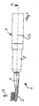
- the electric toothbrush 1 shown in the figures comprises a handpiece 2, to which a brush head 3 can be coupled, wherein in the illustrated embodiment the brush head 3 comprises a brush tube 4, with the aid of which the brush head 3 can be slipped onto the handpiece 2.
- the handpiece 2 in this case comprises a substantially tubular housing 5, which receives an electric drive 6 and a power source, in particular in the form of a battery or a rechargeable battery for this purpose, as well as not shown actuating and control elements.
- a power source in particular in the form of a battery or a rechargeable battery for this purpose, as well as not shown actuating and control elements.
- the drive 6 is arranged in the front part of the interior of the housing 5 of the handpiece 2 and comprises a transformer 7 in the form of a rigid rod, which frontally through an opening 8 from the housing 5 protrudes.
- a transformer 7 in the form of a rigid rod, which frontally through an opening 8 from the housing 5 protrudes.
- the transformer 7 of the aforementioned bust head 3 can be attached with its brush tube 4, wherein the transformer 7 and the brush head 3 suitable coupling means 9, for example in the form of latching connection means, to the brush head 3 rotatable and resistant to bending with the transformer 7 to connect.
- the transmitter 7 is mounted in the region of the passage opening 8 in an elastic sleeve 10, which sits in said passage opening 8.
- This sleeve 10 forms a ball-joint-like pivot bearing, which allows spatial vibration movements of the transformer 7 relative to the housing 5, the transmitter 7 but largely sets axially.
- the sleeve 10 allows a biconical trajectory of the transformer 7, the successive conical tips are in the range of the sleeve 10.
- a drive chassis 11 is fixed, in particular resistant to bending and preferably rigidly connected, so that the transformer 7 performs the same movements as the drive chassis 11.
- the drive chassis 11 carries the actual drive 12, which in the illustrated embodiment of an electric motor 13 with an imbalance 14 in the form of an eccentrically arranged on the motor shaft mass.
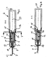
- the transmitter 7 remote from the end of the drive chassis 11 is suspended by a spring means 15 elastically on the housing 5.
- the spring device 15 consists of the in FIG. 6 shown in more detail labyrinth spring 16.
- the spring 16 has in the illustrated embodiment a central mounting portion 17 which is articulated via spring arms 18 and 19 to an outer mounting portion 20 so that the central mounting portion 17 relative to the outer mounting portion 20 under deformation of the spring arms 18 and 19 is movable.
- the central mounting portion 17 is advantageously rigid, in particular non-positive and positive, on the drive 12, in particular the front side of the drive chassis 11, attached. This could basically be provided a screw.
- the spring 16 is riveted to the drive chassis 11.
- the spring 16 is firmly clamped with its outer mounting portion 20 in the housing 5.
- the mounting portion 20 consists of a circumferential, substantially rectangular mounting frame, on whose opposite legs 20a and 20b, the aforementioned spring arms 18 and 19 are attached.
- said mounting frame 20 may be clamped between two portions of the housing 5.
- the mounting frame 20 can be clamped between the joints of the screwed housing halves.
- the mounting frame 20 comprises an orientation coding 21 which cooperates with an orientation coding on the housing 5, so that the spring device 15 is to be mounted in a predetermined orientation relative to the housing.
- orientation coding 21 suitable asymmetries can serve.
- the radiationscod ist 21 consists of a tab-like projection on the mounting frame 20 and an associated recess in the housing. Said lobed or nose-shaped projection can engage in the associated recess in the housing 5, so that the orientation of the spring device 15, in particular the rotational orientation with respect to the toothbrush longitudinal axis 23, is fixed.
- the spring device 15 has different spring constants or hardnesses in different axes.
- the spring arms 18 and 19 are each formed substantially L-shaped, wherein the two legs of each spring arm 18 and 19 are formed differently long.
- the two Federarmabitese 18a and 19a each extending substantially parallel to the X-axis, shorter than the Federarmabitese 18b and 19b, which are substantially parallel to the Y-axis and thus substantially perpendicular to the aforementioned Federarmabites 18a and 19a extend.
- spring 16 in the direction of the X-axis has a lower spring hardness than in the direction of the Y-axis, ie the hinged to the central mounting portion 17 drive 6 is in the direction of the X-axis (see. FIG. 6 ) easier and more deflectable than in the direction of the Y-axis.
- the difference in the spring constants With respect to the X-axis and the Y-axis of the spring 16 may be chosen basically different and is preferably adapted to the training and drive frequency of the drive 6.
- the spring stiffness of the spring 16 in the direction of the Y axis can be at least 25% greater than the spring hardness in the X direction.
- the greater spring stiffness is advantageously provided in the direction corresponding to the poking direction or the main direction 24 of the bristles of the brush head 3, while the softer spring hardness in the direction of the X axis is substantially perpendicular to the toothbrush longitudinal axis 23 and the aforementioned main direction 24 of the bristles of the brush head 3 extends.
- FIG. 4 showing the brush head 3 in front view, the orientation of the X and Y axes of the spring means 15 located.
- a substantially elliptical trajectory 25 (see. FIG. 4 ), whose longitudinal axis is preferably about ten to thirty times, preferably about twenty times, larger than its transverse axis (see. FIG. 4 ).
- the larger amplitude occurs essentially in the aforementioned X-direction, while the smaller amplitude of the oscillation movement occurs in the aforementioned Y-direction.
- the bristle field on the brush head 3 receives only a slight poking movement corresponding to the oscillation in the Y direction and a larger wiping movement parallel to the tooth flanks with a larger amplitude corresponding to the oscillation in the X direction.
- the elliptical trajectory shown in FIG. 4 can also assume a different angular position with regard to the x or y axis, but nevertheless the poking movement in the y direction should be substantially smaller than the wiping movement in the x direction.
- the vibration movement of the drive 6 along the in FIG. 4 shown elliptical trajectory implemented in a tumbling motion of the transformer 7 on a double cone, which are mutually standing tips in the region of the bearing sleeve 10. It is understood that According to the lever ratios, the circumferential oscillatory movement of the brush head 3 can be greater than the oscillation movement of the drive 6.
- the drive frequency of the drive 6 is adapted to the spring constants of the respective spring device 15 used to compensate for manufacturing tolerances of the spring and the drive, so that in the desired manner results in the elliptical oscillation movement.
- this can be controlled via an adjustable voltage stabilization circuit, by means of which the supply voltage of the electric motor 13 can be set to the correct value and stabilized.
- the power supply and control of the electric motor .13 takes place advantageously not via conventional wires, but sheet metal strips 27, which lead from the motor connections to housing-fixed terminals 28, which are advantageously in the range of the bearing sleeve 10 and thus in the range in which the amplitude of movement of the transformer 7 very small, ie is practically zero.
- a printed circuit board with the housing-fixed terminals 28 may be provided, to which the metal strips 27 are connected.
Landscapes
- Health & Medical Sciences (AREA)
- Dentistry (AREA)
- Epidemiology (AREA)
- Life Sciences & Earth Sciences (AREA)
- Animal Behavior & Ethology (AREA)
- General Health & Medical Sciences (AREA)
- Public Health (AREA)
- Veterinary Medicine (AREA)
- Brushes (AREA)
- Reciprocating, Oscillating Or Vibrating Motors (AREA)
Applications Claiming Priority (2)
| Application Number | Priority Date | Filing Date | Title |
|---|---|---|---|
| DE102006004146A DE102006004146A1 (de) | 2006-01-27 | 2006-01-27 | Elektrische Zahnbürste |
| PCT/EP2006/011969 WO2007085289A1 (de) | 2006-01-27 | 2006-12-13 | Elektrische zahnbürste |
Publications (2)
| Publication Number | Publication Date |
|---|---|
| EP1976451A1 EP1976451A1 (de) | 2008-10-08 |
| EP1976451B1 true EP1976451B1 (de) | 2010-08-04 |
Family
ID=37866269
Family Applications (1)
| Application Number | Title | Priority Date | Filing Date |
|---|---|---|---|
| EP06829546A Not-in-force EP1976451B1 (de) | 2006-01-27 | 2006-12-13 | Elektrische zahnbürste |
Country Status (8)
Families Citing this family (15)
| Publication number | Priority date | Publication date | Assignee | Title |
|---|---|---|---|---|
| US8291537B2 (en) | 2008-01-10 | 2012-10-23 | Nottingham-Spirk Design Associates, Inc. | Oral hygiene device and method of assembly |
| JP5130971B2 (ja) * | 2008-03-18 | 2013-01-30 | オムロンヘルスケア株式会社 | 電動歯ブラシ |
| ATE539700T1 (de) | 2008-06-20 | 2012-01-15 | Braun Gmbh | Elektrische zahnbürste |
| JP2010005187A (ja) * | 2008-06-27 | 2010-01-14 | Panasonic Electric Works Co Ltd | 電動歯ブラシ |
| JP5526825B2 (ja) * | 2010-02-02 | 2014-06-18 | オムロンヘルスケア株式会社 | 口腔ケア装置 |
| EP2584995B1 (en) | 2010-06-22 | 2019-10-16 | Koninklijke Philips N.V. | A mouthpiece for cleaning teeth with a mechanical drive train |
| EP3831340B1 (en) | 2013-03-15 | 2024-08-07 | Water Pik, Inc. | Mechanically-driven, sonic toothbrush and water flosser |
| CN104617732B (zh) * | 2015-01-28 | 2017-04-12 | 上海携福电器有限公司 | 个人清洁护理用具 |
| CN205568226U (zh) | 2015-07-08 | 2016-09-14 | 洁碧有限公司 | 刷牙装置 |
| US10561480B2 (en) | 2016-05-09 | 2020-02-18 | Water Pik, Inc. | Load sensing for oral devices |
| USD844997S1 (en) | 2016-12-15 | 2019-04-09 | Water Pik, Inc. | Toothbrush handle |
| CA3046811C (en) | 2016-12-15 | 2021-10-26 | Water Pik, Inc. | Brushing device with illumination features |
| USD845636S1 (en) | 2016-12-15 | 2019-04-16 | Water Pik, Inc. | Toothbrush handle |
| ES2850353T3 (es) * | 2017-11-02 | 2021-08-27 | Braun Gmbh | Dispositivo de higiene personal |
| KR102319278B1 (ko) * | 2021-02-09 | 2021-10-28 | 대구보건대학교산학협력단 | 진동형 스파출라 장치 |
Family Cites Families (10)
| Publication number | Priority date | Publication date | Assignee | Title |
|---|---|---|---|---|
| US3196299A (en) * | 1963-07-05 | 1965-07-20 | Scovill Manufacturing Co | Portable electric unit for toothbrush or the like |
| US3967617A (en) * | 1974-11-25 | 1976-07-06 | Alston, Inc. | Mechanical gum massager |
| DE2607820C2 (de) * | 1976-02-26 | 1985-06-27 | Blendax-Werke R. Schneider Gmbh & Co, 6500 Mainz | Mechanisch oder elektrisch angetriebene Zahnbürste |
| CN2149185Y (zh) * | 1993-03-31 | 1993-12-15 | 薛玉萍 | 复合运动式自动牙刷 |
| DE29515288U1 (de) * | 1995-09-23 | 1995-11-23 | Rowenta-Werke GmbH, 63071 Offenbach | Elektrische Zahnbürste |
| US5827064A (en) * | 1996-08-30 | 1998-10-27 | Sonex International Corp. | Orbitally or reciprocally vibrating method for interproximal plaque removal |
| CN1187341A (zh) * | 1997-12-09 | 1998-07-15 | 朱杰 | 电动牙刷 |
| EP1404245A4 (en) * | 2001-07-12 | 2006-04-05 | Water Pik Inc | TWO-TONE ORAL HYGIENE DEVICE |
| US6859968B2 (en) * | 2002-06-24 | 2005-03-01 | Koninklijke Philips Electronics N.V. | Nodal mounted system for driving a power appliance |
| US7398575B2 (en) * | 2004-02-17 | 2008-07-15 | Church & Dwight Co., Inc. | Electric toothbrush having a flexible drive shaft |
-
2006
- 2006-01-27 DE DE102006004146A patent/DE102006004146A1/de not_active Withdrawn
- 2006-12-13 US US12/162,410 patent/US8196245B2/en not_active Expired - Fee Related
- 2006-12-13 CA CA002637457A patent/CA2637457A1/en not_active Abandoned
- 2006-12-13 CN CN200680051791.4A patent/CN101336096B/zh not_active Expired - Fee Related
- 2006-12-13 AT AT06829546T patent/ATE476153T1/de active
- 2006-12-13 EP EP06829546A patent/EP1976451B1/de not_active Not-in-force
- 2006-12-13 DE DE502006007615T patent/DE502006007615D1/de active Active
- 2006-12-13 JP JP2008551663A patent/JP5225860B2/ja not_active Expired - Fee Related
- 2006-12-13 WO PCT/EP2006/011969 patent/WO2007085289A1/de active Application Filing
Also Published As
| Publication number | Publication date |
|---|---|
| DE102006004146A1 (de) | 2007-08-02 |
| JP2009524459A (ja) | 2009-07-02 |
| CN101336096B (zh) | 2013-06-12 |
| DE502006007615D1 (de) | 2010-09-16 |
| EP1976451A1 (de) | 2008-10-08 |
| JP5225860B2 (ja) | 2013-07-03 |
| CA2637457A1 (en) | 2007-08-02 |
| WO2007085289A1 (de) | 2007-08-02 |
| CN101336096A (zh) | 2008-12-31 |
| US8196245B2 (en) | 2012-06-12 |
| ATE476153T1 (de) | 2010-08-15 |
| US20090188058A1 (en) | 2009-07-30 |
Similar Documents
| Publication | Publication Date | Title |
|---|---|---|
| EP1976451B1 (de) | Elektrische zahnbürste | |
| EP1424955B1 (de) | Zahnbürste | |
| EP0793455B1 (de) | Bürstenteil für eine elektrische zahnbürste | |
| EP1560538B1 (de) | Elektrische zahnbürste und zahnbürstenkopf hierfür | |
| EP0850027B1 (de) | Elektrische zahnbürste | |
| EP0977521B1 (de) | Bürstenteil für eine elektrische zahnbürste | |
| EP0656489B1 (de) | Vorrichtung zur Umwandlung einer Drehbewegung mittels eines Exzenters in eine oszillierende Bewegung | |
| DE10206493A1 (de) | Zahnbürste | |
| WO1996013224A1 (de) | Bürstenteil für eine elektrische zahnbürste | |
| DE202008007730U1 (de) | Elektrischer Schwingantrieb | |
| EP1746296A2 (de) | Kugelgelenklenker | |
| DE102005048618B4 (de) | Gehörknöchelchenprothese mit elastischem Drehgelenk | |
| EP2032401A1 (de) | Scheibenwischvorrichtung, insbesondere für ein kraftfahrzeug | |
| DE102019129756B4 (de) | Steuervorrichtung für eine Arbeitsmaschine | |
| DE60225000T2 (de) | Linearer kompressor | |
| EP2195211A1 (de) | Wischanlage mit einem wischantrieb zum antrieb eines wischgestänges | |
| EP2692583B1 (de) | Verstelleinrichtung für einen Kraftfahrzeugscheinwerfer | |
| DE102006061632A1 (de) | Scheibenwischerantrieb | |
| DE202023104135U1 (de) | Rotierende Ersatzkopfvorrichtung für elektrische Zahnbürsten | |
| DE102022126135A1 (de) | Luftleitvorrichtung einer Kraftfahrzeugkarosserie eines Kraftfahrzeugs | |
| DE3128540A1 (de) | Verstellvorrichtung fuer einen fahrzeug-rueckspiegel | |
| DE102019129757A1 (de) | Schaltblock einer Steuervorrichtung für eine Arbeitsmaschine | |
| EP2450243B1 (de) | Wischergetriebe | |
| DE102004038926B4 (de) | Zahnbürste mit variablem Borstenprofil | |
| DE102018204195A1 (de) | Spindelantrieb und Komfortantrieb mit einem Spindelantrieb |
Legal Events
| Date | Code | Title | Description |
|---|---|---|---|
| PUAI | Public reference made under article 153(3) epc to a published international application that has entered the european phase |
Free format text: ORIGINAL CODE: 0009012 |
|
| 17P | Request for examination filed |
Effective date: 20080617 |
|
| AK | Designated contracting states |
Kind code of ref document: A1 Designated state(s): AT BE BG CH CY CZ DE DK EE ES FI FR GB GR HU IE IS IT LI LT LU LV MC NL PL PT RO SE SI SK TR |
|
| RIN1 | Information on inventor provided before grant (corrected) |
Inventor name: HAAS, MARTIN Inventor name: RINGELMANN, MANFRED Inventor name: BORNHEIMER, HEIKO Inventor name: SCHMID, MICHAEL Inventor name: JUNG, PHILIPP Inventor name: SCHWARZ-HARTMANN, ARMIN Inventor name: FRITSCH, THOMAS |
|
| 17Q | First examination report despatched |
Effective date: 20081219 |
|
| GRAP | Despatch of communication of intention to grant a patent |
Free format text: ORIGINAL CODE: EPIDOSNIGR1 |
|
| GRAS | Grant fee paid |
Free format text: ORIGINAL CODE: EPIDOSNIGR3 |
|
| GRAA | (expected) grant |
Free format text: ORIGINAL CODE: 0009210 |
|
| AK | Designated contracting states |
Kind code of ref document: B1 Designated state(s): AT BE BG CH CY CZ DE DK EE ES FI FR GB GR HU IE IS IT LI LT LU LV MC NL PL PT RO SE SI SK TR |
|
| REG | Reference to a national code |
Ref country code: GB Ref legal event code: FG4D Free format text: NOT ENGLISH |
|
| REG | Reference to a national code |
Ref country code: CH Ref legal event code: EP |
|
| REG | Reference to a national code |
Ref country code: IE Ref legal event code: FG4D Free format text: LANGUAGE OF EP DOCUMENT: GERMAN |
|
| REF | Corresponds to: |
Ref document number: 502006007615 Country of ref document: DE Date of ref document: 20100916 Kind code of ref document: P |
|
| REG | Reference to a national code |
Ref country code: NL Ref legal event code: T3 |
|
| LTIE | Lt: invalidation of european patent or patent extension |
Effective date: 20100804 |
|
| PG25 | Lapsed in a contracting state [announced via postgrant information from national office to epo] |
Ref country code: FI Free format text: LAPSE BECAUSE OF FAILURE TO SUBMIT A TRANSLATION OF THE DESCRIPTION OR TO PAY THE FEE WITHIN THE PRESCRIBED TIME-LIMIT Effective date: 20100804 Ref country code: LT Free format text: LAPSE BECAUSE OF FAILURE TO SUBMIT A TRANSLATION OF THE DESCRIPTION OR TO PAY THE FEE WITHIN THE PRESCRIBED TIME-LIMIT Effective date: 20100804 |
|
| PG25 | Lapsed in a contracting state [announced via postgrant information from national office to epo] |
Ref country code: CY Free format text: LAPSE BECAUSE OF FAILURE TO SUBMIT A TRANSLATION OF THE DESCRIPTION OR TO PAY THE FEE WITHIN THE PRESCRIBED TIME-LIMIT Effective date: 20100804 Ref country code: BG Free format text: LAPSE BECAUSE OF FAILURE TO SUBMIT A TRANSLATION OF THE DESCRIPTION OR TO PAY THE FEE WITHIN THE PRESCRIBED TIME-LIMIT Effective date: 20101104 Ref country code: IS Free format text: LAPSE BECAUSE OF FAILURE TO SUBMIT A TRANSLATION OF THE DESCRIPTION OR TO PAY THE FEE WITHIN THE PRESCRIBED TIME-LIMIT Effective date: 20101204 Ref country code: PL Free format text: LAPSE BECAUSE OF FAILURE TO SUBMIT A TRANSLATION OF THE DESCRIPTION OR TO PAY THE FEE WITHIN THE PRESCRIBED TIME-LIMIT Effective date: 20100804 Ref country code: PT Free format text: LAPSE BECAUSE OF FAILURE TO SUBMIT A TRANSLATION OF THE DESCRIPTION OR TO PAY THE FEE WITHIN THE PRESCRIBED TIME-LIMIT Effective date: 20101206 Ref country code: SI Free format text: LAPSE BECAUSE OF FAILURE TO SUBMIT A TRANSLATION OF THE DESCRIPTION OR TO PAY THE FEE WITHIN THE PRESCRIBED TIME-LIMIT Effective date: 20100804 |
|
| REG | Reference to a national code |
Ref country code: IE Ref legal event code: FD4D |
|
| PG25 | Lapsed in a contracting state [announced via postgrant information from national office to epo] |
Ref country code: GR Free format text: LAPSE BECAUSE OF FAILURE TO SUBMIT A TRANSLATION OF THE DESCRIPTION OR TO PAY THE FEE WITHIN THE PRESCRIBED TIME-LIMIT Effective date: 20101105 Ref country code: SE Free format text: LAPSE BECAUSE OF FAILURE TO SUBMIT A TRANSLATION OF THE DESCRIPTION OR TO PAY THE FEE WITHIN THE PRESCRIBED TIME-LIMIT Effective date: 20100804 Ref country code: LV Free format text: LAPSE BECAUSE OF FAILURE TO SUBMIT A TRANSLATION OF THE DESCRIPTION OR TO PAY THE FEE WITHIN THE PRESCRIBED TIME-LIMIT Effective date: 20100804 |
|
| PG25 | Lapsed in a contracting state [announced via postgrant information from national office to epo] |
Ref country code: IE Free format text: LAPSE BECAUSE OF FAILURE TO SUBMIT A TRANSLATION OF THE DESCRIPTION OR TO PAY THE FEE WITHIN THE PRESCRIBED TIME-LIMIT Effective date: 20100804 Ref country code: DK Free format text: LAPSE BECAUSE OF FAILURE TO SUBMIT A TRANSLATION OF THE DESCRIPTION OR TO PAY THE FEE WITHIN THE PRESCRIBED TIME-LIMIT Effective date: 20100804 |
|
| PG25 | Lapsed in a contracting state [announced via postgrant information from national office to epo] |
Ref country code: CZ Free format text: LAPSE BECAUSE OF FAILURE TO SUBMIT A TRANSLATION OF THE DESCRIPTION OR TO PAY THE FEE WITHIN THE PRESCRIBED TIME-LIMIT Effective date: 20100804 Ref country code: SK Free format text: LAPSE BECAUSE OF FAILURE TO SUBMIT A TRANSLATION OF THE DESCRIPTION OR TO PAY THE FEE WITHIN THE PRESCRIBED TIME-LIMIT Effective date: 20100804 Ref country code: RO Free format text: LAPSE BECAUSE OF FAILURE TO SUBMIT A TRANSLATION OF THE DESCRIPTION OR TO PAY THE FEE WITHIN THE PRESCRIBED TIME-LIMIT Effective date: 20100804 Ref country code: EE Free format text: LAPSE BECAUSE OF FAILURE TO SUBMIT A TRANSLATION OF THE DESCRIPTION OR TO PAY THE FEE WITHIN THE PRESCRIBED TIME-LIMIT Effective date: 20100804 Ref country code: IT Free format text: LAPSE BECAUSE OF FAILURE TO SUBMIT A TRANSLATION OF THE DESCRIPTION OR TO PAY THE FEE WITHIN THE PRESCRIBED TIME-LIMIT Effective date: 20100804 |
|
| PLBE | No opposition filed within time limit |
Free format text: ORIGINAL CODE: 0009261 |
|
| STAA | Information on the status of an ep patent application or granted ep patent |
Free format text: STATUS: NO OPPOSITION FILED WITHIN TIME LIMIT |
|
| BERE | Be: lapsed |
Owner name: BRAUN G.M.B.H. Effective date: 20101231 |
|
| PG25 | Lapsed in a contracting state [announced via postgrant information from national office to epo] |
Ref country code: ES Free format text: LAPSE BECAUSE OF FAILURE TO SUBMIT A TRANSLATION OF THE DESCRIPTION OR TO PAY THE FEE WITHIN THE PRESCRIBED TIME-LIMIT Effective date: 20101115 |
|
| 26N | No opposition filed |
Effective date: 20110506 |
|
| PG25 | Lapsed in a contracting state [announced via postgrant information from national office to epo] |
Ref country code: MC Free format text: LAPSE BECAUSE OF NON-PAYMENT OF DUE FEES Effective date: 20101231 |
|
| REG | Reference to a national code |
Ref country code: CH Ref legal event code: PL |
|
| REG | Reference to a national code |
Ref country code: DE Ref legal event code: R097 Ref document number: 502006007615 Country of ref document: DE Effective date: 20110506 |
|
| PG25 | Lapsed in a contracting state [announced via postgrant information from national office to epo] |
Ref country code: BE Free format text: LAPSE BECAUSE OF NON-PAYMENT OF DUE FEES Effective date: 20101231 |
|
| PG25 | Lapsed in a contracting state [announced via postgrant information from national office to epo] |
Ref country code: LI Free format text: LAPSE BECAUSE OF NON-PAYMENT OF DUE FEES Effective date: 20101231 Ref country code: CH Free format text: LAPSE BECAUSE OF NON-PAYMENT OF DUE FEES Effective date: 20101231 |
|
| PG25 | Lapsed in a contracting state [announced via postgrant information from national office to epo] |
Ref country code: HU Free format text: LAPSE BECAUSE OF FAILURE TO SUBMIT A TRANSLATION OF THE DESCRIPTION OR TO PAY THE FEE WITHIN THE PRESCRIBED TIME-LIMIT Effective date: 20110205 Ref country code: LU Free format text: LAPSE BECAUSE OF NON-PAYMENT OF DUE FEES Effective date: 20101213 |
|
| PG25 | Lapsed in a contracting state [announced via postgrant information from national office to epo] |
Ref country code: TR Free format text: LAPSE BECAUSE OF FAILURE TO SUBMIT A TRANSLATION OF THE DESCRIPTION OR TO PAY THE FEE WITHIN THE PRESCRIBED TIME-LIMIT Effective date: 20100804 |
|
| REG | Reference to a national code |
Ref country code: AT Ref legal event code: MM01 Ref document number: 476153 Country of ref document: AT Kind code of ref document: T Effective date: 20111213 |
|
| PG25 | Lapsed in a contracting state [announced via postgrant information from national office to epo] |
Ref country code: AT Free format text: LAPSE BECAUSE OF NON-PAYMENT OF DUE FEES Effective date: 20111213 |
|
| REG | Reference to a national code |
Ref country code: FR Ref legal event code: PLFP Year of fee payment: 10 |
|
| REG | Reference to a national code |
Ref country code: FR Ref legal event code: PLFP Year of fee payment: 11 |
|
| REG | Reference to a national code |
Ref country code: FR Ref legal event code: PLFP Year of fee payment: 12 |
|
| PGFP | Annual fee paid to national office [announced via postgrant information from national office to epo] |
Ref country code: NL Payment date: 20181213 Year of fee payment: 13 Ref country code: DE Payment date: 20181127 Year of fee payment: 13 |
|
| PGFP | Annual fee paid to national office [announced via postgrant information from national office to epo] |
Ref country code: FR Payment date: 20181120 Year of fee payment: 13 Ref country code: GB Payment date: 20181212 Year of fee payment: 13 |
|
| REG | Reference to a national code |
Ref country code: DE Ref legal event code: R119 Ref document number: 502006007615 Country of ref document: DE |
|
| REG | Reference to a national code |
Ref country code: NL Ref legal event code: MM Effective date: 20200101 |
|
| GBPC | Gb: european patent ceased through non-payment of renewal fee |
Effective date: 20191213 |
|
| PG25 | Lapsed in a contracting state [announced via postgrant information from national office to epo] |
Ref country code: NL Free format text: LAPSE BECAUSE OF NON-PAYMENT OF DUE FEES Effective date: 20200101 |
|
| PG25 | Lapsed in a contracting state [announced via postgrant information from national office to epo] |
Ref country code: DE Free format text: LAPSE BECAUSE OF NON-PAYMENT OF DUE FEES Effective date: 20200701 Ref country code: GB Free format text: LAPSE BECAUSE OF NON-PAYMENT OF DUE FEES Effective date: 20191213 Ref country code: FR Free format text: LAPSE BECAUSE OF NON-PAYMENT OF DUE FEES Effective date: 20191231 |