EP1976285A1 - Démodulateur numérique et procédé pour la démodulation de signaux de télévision analogiques - Google Patents
Démodulateur numérique et procédé pour la démodulation de signaux de télévision analogiques Download PDFInfo
- Publication number
- EP1976285A1 EP1976285A1 EP07006801A EP07006801A EP1976285A1 EP 1976285 A1 EP1976285 A1 EP 1976285A1 EP 07006801 A EP07006801 A EP 07006801A EP 07006801 A EP07006801 A EP 07006801A EP 1976285 A1 EP1976285 A1 EP 1976285A1
- Authority
- EP
- European Patent Office
- Prior art keywords
- signal
- video signal
- frequency
- filter
- video
- Prior art date
- Legal status (The legal status is an assumption and is not a legal conclusion. Google has not performed a legal analysis and makes no representation as to the accuracy of the status listed.)
- Withdrawn
Links
Images


Classifications
-
- H—ELECTRICITY
- H04—ELECTRIC COMMUNICATION TECHNIQUE
- H04N—PICTORIAL COMMUNICATION, e.g. TELEVISION
- H04N5/00—Details of television systems
- H04N5/44—Receiver circuitry for the reception of television signals according to analogue transmission standards
- H04N5/455—Demodulation-circuits
-
- H—ELECTRICITY
- H04—ELECTRIC COMMUNICATION TECHNIQUE
- H04L—TRANSMISSION OF DIGITAL INFORMATION, e.g. TELEGRAPHIC COMMUNICATION
- H04L27/00—Modulated-carrier systems
- H04L27/02—Amplitude-modulated carrier systems, e.g. using on-off keying; Single sideband or vestigial sideband modulation
- H04L27/06—Demodulator circuits; Receiver circuits
-
- H—ELECTRICITY
- H04—ELECTRIC COMMUNICATION TECHNIQUE
- H04N—PICTORIAL COMMUNICATION, e.g. TELEVISION
- H04N5/00—Details of television systems
- H04N5/44—Receiver circuitry for the reception of television signals according to analogue transmission standards
- H04N5/46—Receiver circuitry for the reception of television signals according to analogue transmission standards for receiving on more than one standard at will
-
- H—ELECTRICITY
- H04—ELECTRIC COMMUNICATION TECHNIQUE
- H04L—TRANSMISSION OF DIGITAL INFORMATION, e.g. TELEGRAPHIC COMMUNICATION
- H04L25/00—Baseband systems
- H04L25/02—Details ; arrangements for supplying electrical power along data transmission lines
- H04L25/03—Shaping networks in transmitter or receiver, e.g. adaptive shaping networks
- H04L25/03006—Arrangements for removing intersymbol interference
- H04L2025/0335—Arrangements for removing intersymbol interference characterised by the type of transmission
- H04L2025/03375—Passband transmission
- H04L2025/03382—Single of vestigal sideband
-
- H—ELECTRICITY
- H04—ELECTRIC COMMUNICATION TECHNIQUE
- H04L—TRANSMISSION OF DIGITAL INFORMATION, e.g. TELEGRAPHIC COMMUNICATION
- H04L27/00—Modulated-carrier systems
- H04L27/0014—Carrier regulation
- H04L2027/0024—Carrier regulation at the receiver end
- H04L2027/0026—Correction of carrier offset
- H04L2027/003—Correction of carrier offset at baseband only
Definitions
- the invention relates to a digital demodulator for analogue television signals.
- the invention also relates to a method for digitally demodulating analogue television signal.
- Analogue television signals are still used in different countries, even if digital TV signals are now becoming more and more popular.
- Conventional analogue television signals comprise a video signal and a sound signal.
- the video signal and the sound signal are demodulated separately in a video demodulation unit and a sound demodulation unit, respectively.
- Different countries throughout the world use different analogue television transmission systems, mostly abbreviated by a capital letter (e.g. system M for U.S.A, system L for France, system B/G or system I for countries with a PAL-system), which use different bandwidths for the video signal, different distances from the video signal to the sound signal or different group delays implemented by different transmitters.
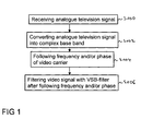
- step S100 an analogue television signal, which comprise a video signal is received.
- Said received analogue television signal may have different distances between the video signal and a sound signal, different bandwidths of the video signal and different group delays all depending of the analogue television signal transmission system which is used.
- step S102 the received analogue television signal is converted into a complex base band.
- this complex base band further processing steps are easier to be performed than in the originally frequency range of the received analogue television signal.
- step S104 a frequency and/or a phase of a carrier of the video signal is followed, for example with the help of a phase locked loop (PLL).
- PLL phase locked loop
- the wording "following of said frequency and/or the phase" of a carrier sometimes is sometimes replaced by "locking to the carrier”.
- the carrier of the video signal in the following text is also referred to as “vision carrier” or “video carrier”.
- the "video signal” might also be referred to as "vision signal”.
- step S106 after said step S104 of following the video signal is filtered with a vestigial sideband filter (VSB filter) since an analogue video signal is vestigial sideband modulated.
- VSB filter normally has a transfer function with a so-called Nyquist-slope, which ensures that after the VSB filter the video signal may be obtained by simply generating a real part of the filtered signal.
- phase locked loop for following the phase and/or the frequency of the carrier of the video signal is situated before the VSB filter with the Nyquist-slope, it is easier for the PLL to lock to the carrier of the video signal, because the analog signal is symmetric in a region adjacent to the carrier. Otherwise, when first filtering with the VSB filter, the spectrum of the analog television signal is no longer symmetric in a region adjacent to the carrier, so that it is more difficult for the phase locked loop to lock to the carrier.
- said analogue television signal comprises a sound signal and said analogue television signal is shifted by a first frequency distance, so that the sound signal in said complex base band is around a frequency 0 and said shifted sound signal is filtered with a low pass filter.
- Such filtering with the low pass filter is easier to perform in the digital domain than building a corresponding band pass filter.
- said first frequency distance is adjusted to a distance between the video signal and the sound signal of different analogue television signals used by different analogue television systems. So it is possible to suppress the sound signal, even for different distances between the video signal and the sound signal by simply adjusting the first frequency distance which shifts the sound signal in said complex base band.
- said video signal is shifted by a second frequency distance so that the video signal is centered around frequency 0 and afterwards said video signal is filtered with a low pass video filter.
- the low pass video filter is easier to build than a corresponding band pass filter.
- said second frequency distance is adjusted to a band-width of said video signal, thereby giving the possibility to optimally centering said video signal even for different bandwidths of different video signals used in different analogue television systems.
- the bandwidth of said low pass video filter is adjusted to a bandwidth of said video signal.
- the low pass video filter can be optimally adjusted to different bandwidths of different video signals in different analogue television systems.
- a group delay is adjusted in accordance with the group delay of a transmitter of said analogue television signal.
- Different analogue television transmission systems use different group delays within their transmitters. By adjusting this group delay it is possible to demodulate different analogue television signals from different analogue television systems.
- a digital demodulator for analogue television signals comprising a base band conversion block, configured to digitally convert said analogue television signal received by a tuner into a complex base band; a phase locked loop (PLL) configured to follow the phase and/or the frequency of a received carrier of said video signal and a vestigial sideband filter, wherein the vestigial side band filter is arranged behind said phase locked loop on a signal demodulation path.
- PLL phase locked loop
- the phase locked loop can easier follow the frequency and/or phase of the received carrier of said video signal, because the video signal is symmetric in a region adjacent to the carrier.
- the digital demodulator further comprises a sound trapping unit arranged between said base band conversion block and said phase locked loop on said signal demodulation path, the sound trapping unit being configured to suppress said sound signal. After this sound trapping unit the sound signal is no longer present on the signal demodulation path, so that it cannot disturb a video demodulation.
- said sound trapping unit is configured to be controlled to notch sound signals, which are situated at different frequency distances from said video signal in different analogue television signals. Since the sound trapping unit can be used to suppress sound signals at different positions, it can be used for different analogue television signals which might have different frequency distances between the video signal and the sound signal.
- a frequency shifting unit configured to shift said sound signal into a notch region of a predetermined transfer function of a sound filter.
- a video filter and a further frequency shifting unit are provided, arranged on said signal demodulation path behind said sound trapping unit, said further frequency shifting unit being configured to shift said video signal so that a center frequency of said video signal is at a center frequency of said video filter in said complex base band.
- the video signal can be centered, e.g. around frequency 0, so that a video filter can be realized as a low pass filter.
- the video filter is configured to have a transfer function, which can be adjusted to different bandwidths of different video signals.
- a transfer function which can be adjusted to different bandwidths of different video signals.
- a group delay equalizer for compensating a group delay of a transmitter of said analogue television signal, wherein said group delay equalizer is adjustable in accordance to different group delays of different transmitters of different analogue television transmission systems.
- said base band conversion block includes the television signal filter with a transfer function, wherein said transfer function is adjustable to different bandwidths of different analogue television signals. As worldwide only three different bandwidths are in use, the corresponding television signal filter might be implemented with three sets of fixed coefficients.
- the digital demodulator comprises a ghost canceling equalizer and a level detector arranged on the signal receiving path behind said ghost canceling equalizer.
- the level detector is configured to detect a level of a synchronization pulse.
- the level is used to control the gain of a base band automatic gain control, which serves as an input signal provider for the digital automatic gain control and the automatic gain control.
- the synchronization pulse is not disturbed anymore by multipath echos, so that there is less crosstalk and the amplitude of the synchronization pulse, which is used for the base band automatic gain control achieves a more constant value.
- a television set is provided said television set or television apparatus comprising a digital demodulator as described above and a tuner, configured to receive said analogue television signal.
- the digital demodulator might be realized as an Application Specific Integrated Circuit (ASIC), which might be controlled by external signals to optimally adjust the corresponding blocks to the analogue television system, in which a television receiver with this ASIC is used.
- ASIC Application Specific Integrated Circuit
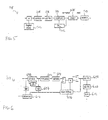
- a top level block diagram of a digital demodulator 200 is depicted, which is a part of a television set 201.
- a tuner 202 is receiving the analogue television signal, which is converted by a base band conversion block 204 into a digital complex base band.
- the digitally converted television signal is input into a channel selection block 206 which outputs a video signal into a video demodulation block 208 and a sound signal into a sound demodulation block 210.
- the output signal from the video demodulation block 208 is input into a base band video block 212 from which control signals for an automatic gain control 214 are provided accordingly adjust the base band conversion block 204 and the tuner 202.
- the base band conversion block 204, the channel selection block 206, the video demodulation block 208 and the base band video block are arranged along a signal demodulation path 211.
- the received analogue television signal is converted from a low intermediate frequency signal into the complex base band.
- frequency shifts can be performed without additional filtering.
- the different blocks use this frequency shift property to center the corresponding signals as needed and to apply filters with real-valued coefficients to the signal, thereby reducing the calculation efforts.
- Fig. 3 a block diagram of the base band conversion block 204 is depicted.
- An analogue-to-digital converter 300 converts the received analogue television signal from the tuner 202 into the digital domain and input the digitized signal into a first frequency shifting unit 302, which is realized by using the so-called Cordic-algorithm (for coordinate rotation digital computer).
- the Cordic-algorithm which is also called digit-by-digit method or Volder's algorithm, is a simple and efficient algorithm to calculate hyperbolic and trigonometric functions. It is commonly used since it only requires small look-up tables, bit shifts and additions to calculate the hyperbolic and trigonometric functions.
- Using a frequency shifting unit 302 for the base band conversion has the advantage that the value of center frequency can be changed easily.
- the signal is converted from a variable input sample rate to a fixed device-internal sample rate by a sample rate converter 304.
- a frequency equalizer 306 and a group delay equalizer 308 are used to compensate for a group delay and a frequency dependency of the tuner 202.
- a channel filter 310 is provided, which has a channel band-width of the analogue television channels. As world-wide only three band-width are in use, this can be implemented as a channel filter with three sets of fixed coefficients. This channel filter 310 is used for cutting off neighboring channels of the analogue TV channels.
- An automatic gain control unit 312 compensates insufficient tuner 202 gain and power loss due to adjacent channels.
- FIG. 4 the block diagram of the channel selection block 206 is depicted.
- a further frequency shifting unit 400 based on the Cordic algorithm is provided to shift the sound carrier to a frequency 0 to afterwards suppress the sound signal with a high pass filter 402. After filtering out the sound signal the remaining video signal is shifted so that a centre frequency of the video signal is centered around 0 in an additional frequency shifting unit 404.
- the additional frequency shifting unit 404 is also realized by a Cordic algorithm, so that a video filter 406 can be used to be adjusted to different vestigial sideband widths and video signal bandwidths after the sound signal has been suppressed.
- a filter with four different bandwidths supports the world-wide used video signal bandwidths.
- the further frequency shift unit 400 and the additional frequency shift unit 404 allow for fully flexible vision carrier to sound carrier distance adjustment.
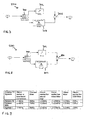
- Fig. 5 a block diagram of the video demodulation block 208 is depicted.
- a vestigial sideband filter 500 is used for reducing the vestigial sideband of the analogue television signal.
- the vestigial sideband filter is arranged on the signal demodulation path 211 behind a phase locked loop PLL 502, which is used together with a fourth frequency shifting unit 504 to adjust the remaining video signal to the vestigial sideband filter.
- the phase locked loop 502 together with the fourth frequency shifting unit 504 are used to shift the video carrier to frequency 0.
- An interpolator 506 and a group delay equalizer 508 to compensate a group delay from the interpolator 506 are provided at the input of the fourth frequency shifting unit 504.
- the video demodulator block 208 implements a Nyquist-slope filter in the vestigial sideband filter 500. All video carrier phase locked loops are using the signal before the vestigial sideband filter 500.
- a group delay equalizer 510 is provided which is fully programmable to allow support of all regionally required group delay characteristics of the video signal of different analogue television systems.
- a digital automatic gain control (AGC) at the input of the video demodulation block 208 can be made very fast to compensate e.g. airplane flutter, which results from reflection at airplanes flying above a roof antenna, which might be connected to the tuner 202.
- AGC automatic gain control
- Fig. 6 the base band video block 212 is depicted in a schematic block diagram.
- a ghost canceling equalizer 600 is provided for canceling ghost signals resulting from multi-path reception.
- a further frequency equalizer 602 and a further loop delay equalizer 604 are provided and afterwards a signal is further handled in a gain and offset block 606 which adjusts the video output level to interface requirements.
- Two further interpolators 608, 610 are used before a digital-to-analogue converter 612 which outputs the video signal to e.g. a display of a television set.
- a level-detector 607 is connected and used for deriving a level of a synchronization pulse of the analogue television signal. Said level is used to control the gain of a base band automatic gain control 614, which serves as an input signal provider for the digital automatic gain control 512 and the automatic gain control 312.
- the level-detector is also connected to the gain offset block 606.
- a first embodiment of a vestigial side band filter 500 is depicted, which embodiment is used for negative-modulated video signals, which is normally present in all analogue television systems with the exception of analogue television system L.
- a complex to real-imaginary converter 700 calculates the real part of a complex input signal and the imaginary part of a complex input signal. The real part is directed via a delay unit 702 to a negative input of an adder 706. The complex part is filtered in a Hilbert FIR-filter 704 and the filtered signal is directed to a positive input of the adder 706. The adder generates a sum signal from the signal as an output signal of the vestigial side band filter 500.
- FIG. 8 For the system L, which is based on a positive-modulated video signal, an embodiment of the vestigial side band filter 500 is depicted in Fig. 8 .
- the complex to real-imaginary converter 700 calculates the real part of the complex input signal and the imaginary part of the complex input signal. The real part is directed via a delay unit 702 to a positive input of the adder 706.
- the complex part is filtered in a Hilbert FIR-filter 704 and the filtered signal is directed to a negative input of the adder 706.
- the adder generates a sum signal from the signal as an output signal of the vestigial side band filter 500.
- the vestigial side band filter 500 can change a negative-modulated video signal into a positive-modulated video signal or a positive-modulated video signal into a negative-modulated video signal. So the following base band video block 212 might be implemented independently of modulation scheme of the video signal.
- the vestigial side band filter 500 can be easily adjusted by simple inverting the input signals of the adder 706.
- Fig. 9 a table summarize the bandwidths and center frequency adjustment for exemplary standards of analogue television systems.
- Fig.9 the corresponding values for the M-system (NTSC) and the two PAL-systems B/G and I are depicted.
- a first column the frequency of the video or vision carrier after the base band conversion in the base band conversion block 204 is shown.
- the bandwidth of the channel filter 310 for the different systems is depicted.
- the position of the vision or video carrier in the sound trapping unit 402 is depicted.
- the position of the vision or video carrier in the video filter 406 is depicted.
- the bandwidth of the video filter 406 is depicted.
- the position of the vision carrier for the VSB-filter 500 is depicted.
- the signal demodulating is performed in the complex base-band, which means that the analog television signal may span from -5 MHz to 5 MHz, if an internal sample rate of 10 MHz is used.
- the signal is shifted in the frequency domain several times to achieve a universal adaptation to all worldwide analogue television broadcast systems.
Landscapes
- Engineering & Computer Science (AREA)
- Signal Processing (AREA)
- Multimedia (AREA)
- Computer Networks & Wireless Communication (AREA)
- Digital Transmission Methods That Use Modulated Carrier Waves (AREA)
- Picture Signal Circuits (AREA)
Priority Applications (4)
| Application Number | Priority Date | Filing Date | Title |
|---|---|---|---|
| EP07006801A EP1976285A1 (fr) | 2007-03-31 | 2007-03-31 | Démodulateur numérique et procédé pour la démodulation de signaux de télévision analogiques |
| BRPI0809504-3A BRPI0809504A2 (pt) | 2007-03-31 | 2008-03-05 | Demodulador digital, aparelho de televisão, e, método para demodular digitalmente sinais de televisão analógicos |
| PCT/EP2008/001755 WO2008119429A1 (fr) | 2007-03-31 | 2008-03-05 | Démodulateur numérique et procédé de démodulation de signaux de télévision analogique |
| EP08716272A EP2342895A1 (fr) | 2007-03-31 | 2008-03-05 | Démodulateur numérique et procédé de démodulation de signaux de télévision analogique |
Applications Claiming Priority (1)
| Application Number | Priority Date | Filing Date | Title |
|---|---|---|---|
| EP07006801A EP1976285A1 (fr) | 2007-03-31 | 2007-03-31 | Démodulateur numérique et procédé pour la démodulation de signaux de télévision analogiques |
Publications (1)
| Publication Number | Publication Date |
|---|---|
| EP1976285A1 true EP1976285A1 (fr) | 2008-10-01 |
Family
ID=38476941
Family Applications (2)
| Application Number | Title | Priority Date | Filing Date |
|---|---|---|---|
| EP07006801A Withdrawn EP1976285A1 (fr) | 2007-03-31 | 2007-03-31 | Démodulateur numérique et procédé pour la démodulation de signaux de télévision analogiques |
| EP08716272A Withdrawn EP2342895A1 (fr) | 2007-03-31 | 2008-03-05 | Démodulateur numérique et procédé de démodulation de signaux de télévision analogique |
Family Applications After (1)
| Application Number | Title | Priority Date | Filing Date |
|---|---|---|---|
| EP08716272A Withdrawn EP2342895A1 (fr) | 2007-03-31 | 2008-03-05 | Démodulateur numérique et procédé de démodulation de signaux de télévision analogique |
Country Status (3)
| Country | Link |
|---|---|
| EP (2) | EP1976285A1 (fr) |
| BR (1) | BRPI0809504A2 (fr) |
| WO (1) | WO2008119429A1 (fr) |
Cited By (2)
| Publication number | Priority date | Publication date | Assignee | Title |
|---|---|---|---|---|
| RU2556429C1 (ru) * | 2014-07-14 | 2015-07-10 | Федеральное государственное бюджетное образовательное учреждение высшего профессионального образования "Воронежский государственный технический университет" | Некогерентный цифровой демодулятор "в целом" кодированных сигналов с фазовой манипуляцией |
| RU2649782C1 (ru) * | 2017-06-15 | 2018-04-04 | федеральное государственное бюджетное образовательное учреждение высшего образования "Национальный исследовательский университет "МЭИ" (ФГБОУ ВО "НИУ "МЭИ") | Цифровой некогерентный демодулятор четырехпозиционных сигналов с относительной фазовой манипуляцией |
Citations (5)
| Publication number | Priority date | Publication date | Assignee | Title |
|---|---|---|---|---|
| US5673293A (en) * | 1994-09-08 | 1997-09-30 | Hitachi America, Ltd. | Method and apparatus for demodulating QAM and VSB signals |
| US6148037A (en) * | 1996-04-24 | 2000-11-14 | Pioneer Electronics Corporation | Sampling timing phase error detector for VSB modulation signal |
| US6356598B1 (en) * | 1998-08-26 | 2002-03-12 | Thomson Licensing S.A. | Demodulator for an HDTV receiver |
| US20050243218A1 (en) * | 2004-04-30 | 2005-11-03 | Yee Dennis G | Video receiver with adaptive image rejection |
| EP1681873A1 (fr) * | 2005-01-14 | 2006-07-19 | Broadcom Corporation | Puce unique HDTV pour la réception analogique et numérique |
-
2007
- 2007-03-31 EP EP07006801A patent/EP1976285A1/fr not_active Withdrawn
-
2008
- 2008-03-05 EP EP08716272A patent/EP2342895A1/fr not_active Withdrawn
- 2008-03-05 WO PCT/EP2008/001755 patent/WO2008119429A1/fr active Application Filing
- 2008-03-05 BR BRPI0809504-3A patent/BRPI0809504A2/pt not_active Application Discontinuation
Patent Citations (5)
| Publication number | Priority date | Publication date | Assignee | Title |
|---|---|---|---|---|
| US5673293A (en) * | 1994-09-08 | 1997-09-30 | Hitachi America, Ltd. | Method and apparatus for demodulating QAM and VSB signals |
| US6148037A (en) * | 1996-04-24 | 2000-11-14 | Pioneer Electronics Corporation | Sampling timing phase error detector for VSB modulation signal |
| US6356598B1 (en) * | 1998-08-26 | 2002-03-12 | Thomson Licensing S.A. | Demodulator for an HDTV receiver |
| US20050243218A1 (en) * | 2004-04-30 | 2005-11-03 | Yee Dennis G | Video receiver with adaptive image rejection |
| EP1681873A1 (fr) * | 2005-01-14 | 2006-07-19 | Broadcom Corporation | Puce unique HDTV pour la réception analogique et numérique |
Cited By (2)
| Publication number | Priority date | Publication date | Assignee | Title |
|---|---|---|---|---|
| RU2556429C1 (ru) * | 2014-07-14 | 2015-07-10 | Федеральное государственное бюджетное образовательное учреждение высшего профессионального образования "Воронежский государственный технический университет" | Некогерентный цифровой демодулятор "в целом" кодированных сигналов с фазовой манипуляцией |
| RU2649782C1 (ru) * | 2017-06-15 | 2018-04-04 | федеральное государственное бюджетное образовательное учреждение высшего образования "Национальный исследовательский университет "МЭИ" (ФГБОУ ВО "НИУ "МЭИ") | Цифровой некогерентный демодулятор четырехпозиционных сигналов с относительной фазовой манипуляцией |
Also Published As
| Publication number | Publication date |
|---|---|
| BRPI0809504A2 (pt) | 2014-09-16 |
| WO2008119429A1 (fr) | 2008-10-09 |
| EP2342895A1 (fr) | 2011-07-13 |
Similar Documents
| Publication | Publication Date | Title |
|---|---|---|
| CN1110942C (zh) | 包括带阻滤波器的数字视频信号处理系统 | |
| JP3499196B2 (ja) | 受信信号劣化補償装置及び方法 | |
| KR101464901B1 (ko) | 범용 텔레비전 수신기 | |
| US5235424A (en) | Automatic gain control system for a high definition television signal receiver | |
| EP0813345A2 (fr) | Dispositif et méthode pour démodulation digitale | |
| US8295404B1 (en) | Timing tracker for DPSK receiver | |
| EP1585322A1 (fr) | Separateur audio/video | |
| CA2338411C (fr) | Recepteur et methode blr/qam | |
| US20020105599A1 (en) | VSB demodulating device and method in digital TV receiver | |
| KR100930988B1 (ko) | 위상 추적 시스템 및 방법 | |
| KR100515551B1 (ko) | 방송수신장치 | |
| JP2003218755A (ja) | 多重伝送路を通じて伝送された放送信号の復元時に発生する位相エラーを補償することができるデジタル放送受信機のエラー復元装置 | |
| KR100246800B1 (ko) | 인터캐리어 신호를 이용하여 엔.티.에스.씨 간섭을 검파하는 디지탈 텔레비젼 수신기 | |
| EP1976285A1 (fr) | Démodulateur numérique et procédé pour la démodulation de signaux de télévision analogiques | |
| KR100896275B1 (ko) | 반송파 복구 장치 및 방법 | |
| KR19990060480A (ko) | 디지털 잔류측파대 복조장치 | |
| KR100425104B1 (ko) | 반송파 복구 장치 | |
| US20090122203A1 (en) | Demodulator, method and receiver for demodulation | |
| KR100510632B1 (ko) | 디지털 잔류측파대 복조장치 | |
| US8942328B2 (en) | Timing recovery apparatus and method | |
| KR100956813B1 (ko) | 디지탈 tv 수신기의 극성 보정 장치 | |
| KR100451741B1 (ko) | 반송파 복구 장치 | |
| KR20030077204A (ko) | 유럽형의 지상파/케이블 공용 디지털 텔레비젼 시스템의복조기 | |
| JP3576816B2 (ja) | ディジタルテレビジョン信号が同一チャネル干渉アナログテレビジョン信号を伴う時期を検出する方法および装置 | |
| KR20040006309A (ko) | 디지털 tv 수신기에서의 vsb 복조 장치 |
Legal Events
| Date | Code | Title | Description |
|---|---|---|---|
| PUAI | Public reference made under article 153(3) epc to a published international application that has entered the european phase |
Free format text: ORIGINAL CODE: 0009012 |
|
| AK | Designated contracting states |
Kind code of ref document: A1 Designated state(s): AT BE BG CH CY CZ DE DK EE ES FI FR GB GR HU IE IS IT LI LT LU LV MC MT NL PL PT RO SE SI SK TR |
|
| AX | Request for extension of the european patent |
Extension state: AL BA HR MK RS |
|
| AKX | Designation fees paid | ||
| STAA | Information on the status of an ep patent application or granted ep patent |
Free format text: STATUS: THE APPLICATION IS DEEMED TO BE WITHDRAWN |
|
| 18D | Application deemed to be withdrawn |
Effective date: 20090402 |
|
| REG | Reference to a national code |
Ref country code: DE Ref legal event code: 8566 |