EP1975971A1 - Device for controlling an electric protection device and electric protection device including same - Google Patents
Device for controlling an electric protection device and electric protection device including same Download PDFInfo
- Publication number
- EP1975971A1 EP1975971A1 EP08354012A EP08354012A EP1975971A1 EP 1975971 A1 EP1975971 A1 EP 1975971A1 EP 08354012 A EP08354012 A EP 08354012A EP 08354012 A EP08354012 A EP 08354012A EP 1975971 A1 EP1975971 A1 EP 1975971A1
- Authority
- EP
- European Patent Office
- Prior art keywords
- hook
- plate
- lever
- contacts
- link
- Prior art date
- Legal status (The legal status is an assumption and is not a legal conclusion. Google has not performed a legal analysis and makes no representation as to the accuracy of the status listed.)
- Granted
Links
- 230000004224 protection Effects 0.000 title claims description 9
- 230000005540 biological transmission Effects 0.000 claims abstract description 15
- 230000009467 reduction Effects 0.000 claims abstract description 11
- 230000007246 mechanism Effects 0.000 claims description 15
- BASFCYQUMIYNBI-UHFFFAOYSA-N platinum Chemical compound [Pt] BASFCYQUMIYNBI-UHFFFAOYSA-N 0.000 claims description 6
- 238000000926 separation method Methods 0.000 claims description 3
- 229910052697 platinum Inorganic materials 0.000 claims 1
- XEEYBQQBJWHFJM-UHFFFAOYSA-N Iron Chemical compound [Fe] XEEYBQQBJWHFJM-UHFFFAOYSA-N 0.000 abstract 2
- 230000007547 defect Effects 0.000 abstract 1
- 229910052742 iron Inorganic materials 0.000 abstract 1
- 230000001960 triggered effect Effects 0.000 description 3
- 240000008042 Zea mays Species 0.000 description 2
- 208000010543 22q11.2 deletion syndrome Diseases 0.000 description 1
- 230000009471 action Effects 0.000 description 1
- 230000003247 decreasing effect Effects 0.000 description 1
- 238000006073 displacement reaction Methods 0.000 description 1
- 230000000694 effects Effects 0.000 description 1
- 210000003127 knee Anatomy 0.000 description 1
- 238000013021 overheating Methods 0.000 description 1
Images


Classifications
-
- H—ELECTRICITY
- H01—ELECTRIC ELEMENTS
- H01H—ELECTRIC SWITCHES; RELAYS; SELECTORS; EMERGENCY PROTECTIVE DEVICES
- H01H71/00—Details of the protective switches or relays covered by groups H01H73/00 - H01H83/00
- H01H71/10—Operating or release mechanisms
- H01H71/50—Manual reset mechanisms which may be also used for manual release
- H01H71/52—Manual reset mechanisms which may be also used for manual release actuated by lever
- H01H71/526—Manual reset mechanisms which may be also used for manual release actuated by lever the lever forming a toggle linkage with a second lever, the free end of which is directly and releasably engageable with a contact structure
Definitions
- the patent is also known FR 2,616,583 describing a control mechanism of a miniature electric circuit breaker having the features mentioned above.
- the assembly comprising the transmission link, the hook, and the trip lever is a reduction stage allowing a reduction of the triggering force.
- the force of the rod exerts a torque on the hook hook.
- This geometry does not allow to be optimized in order to further reduce the gripping force for reasons of size of the mechanism in relation to the standard size of the modular circuit breaker poles. As a result, the size of the magnetic and thermal protections can not be further reduced.
- the present invention solves these problems and provides a device for controlling an electrical apparatus to improve the performance of this apparatus.
- the present invention relates to a control device of an electrical protection apparatus of the kind mentioned above.
- This device is characterized in that the transmission rod, in locking position of the hooking, bears on the plate and on the locking hook, the relative positions of the two bearing surfaces respectively of the plate and the hook and that the ratio of the two lever arms for the reduction of the force of the rod on the release lever being chosen so that the force applied to the hook is lower than that applied to the plate.
- the relative positions of the two bearing surfaces as well as the ratio of the two lever arms are chosen so that the force applied to the hook is about seven times lower than that applied to the plate.
- the hook and the trigger lever are made in a reduced thickness so as to allow the housing of an anti-pollution screen interposed between the link and the hooking zone between the hook and the trip lever .
- the hook is made of a cut sheet or plastic.
- the hook and the plate each comprise an opening intended to allow the rotation of the plate during an automatic release while the rod is locked in the closed position of the contacts by the joystick.
- the plate also comprises an opening adapted to guide the stroke of the rod to its initial position in support on the plate, when the handle returns to the open position of the contacts after an automatic release.
- this device comprises a spring with two branches fixed on the lever, comprising a first branch adapted to bring the release lever back to its initial position ready for engagement after a release and a second branch capable of bringing back the hook. in a preferred position, in which is created a sufficient clearance between the hook and the lever so as to facilitate hooking of the hook on said bar, after an automatic trigger.
- the invention also relates to an electrical protection device comprising a control device comprising the previously mentioned features taken alone or in combination.
- a miniature electric circuit breaker molded insulating casing 1 comprising a control device 2 according to the invention.
- This device comprises a support device 3 of the movable contact 4, said mobile contact 4 cooperating with a fixed contact 5.
- An opening 7 is provided in the front face 8 of the housing for the passage of a lever 6 mounted pivotally limited on an axis 11 of the housing between a closed position in which the contacts 4,5 are closed, and a position of opening corresponding to the separation of contacts 4,5.
- the lever 6 is equipped with an internal base 9 coupled to a transmission rod 10 to form a toggle device whose articulation 12 is eccentric with respect to the fixed axis 11 of the lever 6.
- the lever 6 is biased in the trigonometric direction towards the position of opening of the contacts by a return spring (not shown).
- the fixed contact 5 is secured to the casing of the electromagnetic release 13.
- the movable contact 4 is fixed to the support device 3 of the movable contact 4, said support 3 being articulated on a pivot 14, the rotating plate 15 being rotatably mounted around a pivot 31.
- a triggering lever 16 controlled by the striker of the electromagnetic release and the bimetal of the thermal release (not shown) or an external auxiliary, is pivotally mounted on an axis 17 carried by the plate 15 with a predetermined offset relative to the pivot aforementioned 14.
- a breakable mechanical connection is provided between the transmission link 10 and the drive plate of the contact support device 3 4. In the locked position, the connection allows the manual control of the mechanism by the lever 6.
- the displacement of the trigger lever 16 to the triggered position under the action of the triggers, causes the momentary rupture of the mechanical link, causing the automatic trigger mechanism , independently of the lever 6.
- the release lever 16 is associated with a return spring 27 for ensuring the automatic restoration of the mechanical link when the lever 6 is actuated to the open position, following a triggering of the mechanism on default.
- the breakable mechanical link comprises a hook 19 pivotally mounted on an axis 20 of the plate 15.
- the spout 21 ( fig.4 ) of the hook 19 cooperates in the locked position of the connection with a retaining catch 22 ( fig.4 )
- the transmission link 10 is coupled to the hook 19 and the plate 15 at a hinge point 23 that can move when triggered in two consecutive openings 24 and 26 of the plate. 15.
- This articulation point 23 is located between the hinge axis 20 ( fig.3 ) of the hook 19 on the plate and the spout 21 ( fig.4 ) of the hook hook.
- the link is a reduction stage in the kinematic chain of the mechanism, allowing a reduction of the triggering force from the magneto-thermal trigger.
- the hook 19 also has a bean-shaped opening or V 25 which, with the openings 24 and 26 of the plate, are intended to allow the rotation of the contact holder plate 15, during a trip, while the link 10 is blocked by the handle 6, itself held in the closed position of the contacts.
- the opening 26 provided in the plate 15 also guides the stroke of the link when the handle returns to the open position of the contacts after a trip.
- the two openings 24,26 of the plate 15 extend relative to each other so as to form a V.
- a bias spring 27 with two branches 28,29 is installed around the axis 17 on the lever 16. One of the branches 28 is intended to return the release lever 16 to its initial position while the other branch 29 polarizes the hook 19 in a preferential position chosen so as to create between the lever 16 and the hook 19 a clearance sufficient to allow the hooking.
- Screen 30 ( figs.3 , 6 and 7 ) integrated in the release lever covers the hooking zone of the release lever 16 with the hook 19. This screen is interposed between the rod and the attachment zone of the hook. It makes it possible to protect the fastening area from projections due to the cut.
- the control device is in a position of the open contacts, the lever being in the open position.
- the lever 6 When the lever 6 is actuated to close the contacts ( fig.2 ), this moves the rod 10 which bears on the plate 15 and on the hook 19 ( fig.2 ).
- the hook 19 is locked on the bar (or lever) trigger.
- the rod 10 bears on the plate 15 and the hook 19, pivots the plate about its axis 31 until the contacts 4,5 close.
- the rod continues its race until crossing the dead point of the knee formed by the lever and the link. Then, the mechanism takes the equilibrium position that keeps the contacts closed as shown on the figure 3 and 4 .
- the handle 6 is actuated until it crosses the dead center of the toggle in the opposite direction.
- the mechanism then reaches the equilibrium position, the contacts being open, when the handle reaches the end of its stroke, position represented on the figure 1 .
- the hook 19 is unlocked, but the handle 6 does not return immediately to its open position.
- the balance of forces exerted by the rod 10 on the mechanism is broken.
- the plate 15 rotates about its axis 31 and opens the contacts, the position shown on the figures 5 and 6 .
- the opening 25 provided inside the hook 19, allows the rotation of the hook about the axis 20 and this opening 25 of the hook and the openings 24,26 of the plate 15, allow the rotation of the plate, the joystick is still maintained in the closed contacts position. Then, the spring of the joystick brings the latter back to the open contacts position and the rod returns the hook to the initial position as shown in FIG. figure 7 .
- the biasing spring 27 of the hook and resetting of the bar puts them in a position allowing the locking of the hook on the bar when the lever is actuated to close the contacts.
- the openings 24,26 provided in the plate 15 participate in the guide of the rod 10 so as to bring it back into position on the platen.
- the link in the normal operating position of the electrical circuit without any fault in the circuit, the link is supported on the contact carrier plate and on the locking hook, the relative positions of the two bearing surfaces as well as the ratio of lever arms X and Y being optimized so that the force that locks the hook is reduced to a minimum.
- the system comprises two stages of reduction. According to the first, the force of the mechanism is taken up largely on the plate and in a smaller part on the hook. According to the second, by a set of lever arms on the hook, the force is multiplied on the trigger lever. Thus, the force required for unlocking can be reduced to a value lower than the solutions of the prior art.
- the invention By virtue of the invention, a reduction in the size of the products is obtained while maintaining or increasing the performance of the device, given that the size of the magnetic and thermal protections can be reduced.
- the heat released by the thermal protections is thereby decreased.
- the operation of the magnetic releases is faster and better since the dynamic stresses are lower.
- the reduction of the gripping force reduces the bearing surface of the hook on the bar and therefore the thickness of the hook and the trigger bar.
- the reduction of the gripping force also makes it possible to produce the cut sheet hook because it is possible to make the hook in a thin sheet.
- the small thickness of the hook and the bar makes it possible to house an anti-pollution screen between, on the one hand, the connecting rod and, on the other hand, the catch zone between the hook and the bar.
- the bias spring thanks to the presence of the bias spring, the dimension chains for hooking the hook on the bar are simplified. Thus, a single spring is used to perform both functions namely resetting the bar and creating a snap.
- the invention applies to any electrical apparatus comprising a mechanism of the type mentioned above, such as a circuit breaker, a switch, a differential switch, a disconnector, auxiliary contacts including modular products etc .
Abstract
Description
La présente invention concerne un dispositif de commande d'un appareil de protection électrique logé dans un boîtier isolant renfermant une paire de contacts fixe et mobile, ledit contact mobile pouvant être actionné soit manuellement par l'intermédiaire d'une manette soit automatiquement, comprenant
- une biellette de transmission accouplée à la manette,
- un dispositif de support du contact mobile comportant une platine montée à rotation sur un pivot et ayant une liaison mécanique brisable avec la biellette de transmission, et
- un levier de déclenchement commandé par un déclencheur pour provoquer en cas de défaut la rupture de la liaison mécanique, entraînant le déclenchement automatique du mécanisme indépendamment de la manette et la séparation des contacts,
- la liaison mécanique brisable étant formée par un cran de retenue du levier de déclenchement coopérant avec un crochet d'accrochage monté à pivotement sur un axe de la platine.
On connaît lebrevet FR 2 589 627
- a transmission link coupled to the joystick,
- a device for supporting the movable contact comprising a plate rotatably mounted on a pivot and having a breakable mechanical connection with the transmission link, and
- a release lever controlled by a trigger to cause, in the event of a fault, the breaking of the mechanical link, causing the automatic triggering of the mechanism independently of the handle and the separation of the contacts,
- the breakable mechanical link being formed by a catch of the release lever cooperating with a hook hook pivotally mounted on an axis of the plate.
The patent is knownFR 2,589,627
On connaît également le brevet
Dans ce document, l'ensemble comprenant la biellette de transmission, le crochet, et le levier de déclenchement constitue un étage démultiplicateur autorisant une réduction de l'effort de déclenchement.
Dans ce mécanisme, la force de la biellette exerce un couple sur le crochet d'accrochage. Cette géométrie ne permet pas d'être optimisée afin de réduire encore davantage la force d'accrochage pour des raisons d'encombrement du mécanisme en relation avec la taille standard des pôles de disjoncteurs modulaires. Par voie de conséquence, la taille des protections magnétiques et thermiques ne peut pas être diminuée davantage.The patent is also known
In this document, the assembly comprising the transmission link, the hook, and the trip lever is a reduction stage allowing a reduction of the triggering force.
In this mechanism, the force of the rod exerts a torque on the hook hook. This geometry does not allow to be optimized in order to further reduce the gripping force for reasons of size of the mechanism in relation to the standard size of the modular circuit breaker poles. As a result, the size of the magnetic and thermal protections can not be further reduced.
Ceci limite les performances des disjoncteurs en raison des échauffements produits par ces dispositifs.This limits the performance of the circuit breakers because of the overheating produced by these devices.
La présente invention résout ces problèmes et propose un dispositif de commande d'un appareil électrique permettant d'améliorer les performances de cet appareil.The present invention solves these problems and provides a device for controlling an electrical apparatus to improve the performance of this apparatus.
A cet effet, la présente invention a pour objet un dispositif de commande d'un appareil de protection électrique du genre précédemment mentionné. Ce dispositif est caractérisé en ce que la biellette de transmission, en position de verrouillage de l'accrochage, prend appui sur la platine et sur le crochet de verrouillage, les positions relatives des deux surfaces d'appui respectivement de la platine et du crochet ainsi que le rapport des deux bras de levier permettant la démultiplication de l'effort de la biellette sur le levier de déclenchement étant choisis de manière que la force appliquée au crochet soit plus faible que celle appliquée à la platine.For this purpose, the present invention relates to a control device of an electrical protection apparatus of the kind mentioned above. This device is characterized in that the transmission rod, in locking position of the hooking, bears on the plate and on the locking hook, the relative positions of the two bearing surfaces respectively of the plate and the hook and that the ratio of the two lever arms for the reduction of the force of the rod on the release lever being chosen so that the force applied to the hook is lower than that applied to the plate.
Selon une caractéristique particulière, les positions relatives des deux surfaces d'appui ainsi que le rapport des deux bras de levier sont choisis de manière que la force appliquée au crochet soit environ sept fois plus faible que celle appliquée à la platine.According to a particular feature, the relative positions of the two bearing surfaces as well as the ratio of the two lever arms are chosen so that the force applied to the hook is about seven times lower than that applied to the plate.
Selon une autre caractéristique particulière, le crochet et le levier de déclenchement sont réalisés dans une épaisseur réduite de manière à permettre le logement d'un écran anti-pollution interposé entre la biellette et la zone d'accrochage entre le crochet et le levier de déclenchement.According to another particular feature, the hook and the trigger lever are made in a reduced thickness so as to allow the housing of an anti-pollution screen interposed between the link and the hooking zone between the hook and the trip lever .
Selon une autre caractéristique, le crochet est réalisé en une tôle découpée ou en plastique.According to another characteristic, the hook is made of a cut sheet or plastic.
Selon une autre caractéristique, le crochet et la platine comportent chacun une ouverture destinée à permettre la rotation de la platine lors d'un déclenchement automatique alors que la biellette est bloquée en position de fermeture des contacts par la manette.According to another characteristic, the hook and the plate each comprise an opening intended to allow the rotation of the plate during an automatic release while the rod is locked in the closed position of the contacts by the joystick.
Selon une autre caractéristique, la platine comporte également une ouverture apte à guider la course de la biellette vers sa position initiale en appui sur la platine, lorsque la manette revient en position d'ouverture des contacts après un déclenchement automatique.According to another characteristic, the plate also comprises an opening adapted to guide the stroke of the rod to its initial position in support on the plate, when the handle returns to the open position of the contacts after an automatic release.
Selon une autre caractéristique, ce dispositif comporte un ressort à deux branches fixé sur le levier, comportant une première branche apte à ramener le levier de déclenchement dans sa position initiale prête à l'accrochage après un déclenchement et une seconde branche apte à ramener le crochet dans une position préférentielle, dans laquelle est créé un jeu suffisant entre le crochet et le levier de manière à faciliter l'accrochage du crochet sur ladite barre, après un déclenchement automatique.According to another characteristic, this device comprises a spring with two branches fixed on the lever, comprising a first branch adapted to bring the release lever back to its initial position ready for engagement after a release and a second branch capable of bringing back the hook. in a preferred position, in which is created a sufficient clearance between the hook and the lever so as to facilitate hooking of the hook on said bar, after an automatic trigger.
L'invention a encore pour objet un appareil de protection électrique comportant un dispositif de commande comportant les caractéristiques précédemment mentionnées prises seules ou en combinaison.The invention also relates to an electrical protection device comprising a control device comprising the previously mentioned features taken alone or in combination.
Mais d'autres avantages et caractéristiques de l'invention apparaîtront mieux dans la description détaillée qui suit et se réfère aux dessins annexés donnés uniquement à titre d'exemple, et dans lesquels :
- La
figure 1 est une vue partielle, en plan, illustrant la partie intérieure d'un disjoncteur équipé d'un dispositif de commande selon une réalisation particulière de l'invention, en position ouverte des contacts et de la manette, - La
figure 2 est une vue identique à la précédente, le dispositif étant dans une position correspondant à un début de fermeture des contacts, - La
figure 3 est une vue identique aux précédentes, dans une position fermée des contacts et de la manette et illustrant l'écran anti-pollution, - La
figure 4 est une vue agrandie de la figure précédente, illustrant plus particulièrement le dispositif de commande dans la position fermée des contacts et de la manette correspondant à la figure précédente, - La
figure 5 est une vue partielle en plan, illustrant plus particulièrement le dispositif de commande dans une position déclenchée, la manette étant maintenue dans une position fermée, - La
figure 6 est une vue identique aux précédentes, illustrant le dispositif de commande dans la même position que lafigure 5 , mais illustrant en plus l'écran anti-pollution, - La
figure 7 est une vue identique à lafigure 1 , mais illustrant en plus l'écran anti-pollution.
- The
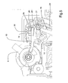
figure 1 is a partial view, in plan, illustrating the inner part of a circuit breaker equipped with a control device according to a particular embodiment of the invention, in the open position of the contacts and the handle, - The
figure 2 is a view identical to the previous one, the device being in a position corresponding to a beginning of closure of the contacts, - The
figure 3 is a view identical to the previous ones, in a closed position of the contacts and the joystick and illustrating the anti-pollution screen, - The
figure 4 is an enlarged view of the previous figure, illustrating more particularly the control device in the closed position of the contacts and the lever corresponding to the previous figure, - The
figure 5 is a partial plan view, illustrating more particularly the control device in a triggered position, the lever being held in a closed position, - The
figure 6 is a view identical to the previous ones, illustrating the control device in the same position as thefigure 5 , but also illustrating the anti-pollution screen, - The
figure 7 is a view identical to thefigure 1 , but also illustrating the anti-pollution screen.
Sur les figures, on voit un disjoncteur électrique miniature à boîtier isolant 1 moulé comportant un dispositif de commande 2 selon l'invention. Ce dispositif comporte un dispositif de support 3 du contact mobile 4, ledit contact mobile 4 coopérant avec un contact fixe 5.
Une ouverture 7 est prévue dans la face avant 8 du boîtier pour le passage d'une manette 6 montée à pivotement limité sur un axe 11 du boîtier entre une position de fermeture dans laquelle les contacts 4,5 sont fermés, et une position d'ouverture correspondant à la séparation des contacts 4,5. La manette 6 est équipée d'une embase interne 9 accouplée à une biellette de transmission 10 pour constituer un dispositif à genouillère dont l'articulation 12 se trouve excentrée par rapport à l'axe fixe 11 de la manette 6.
La manette 6 est sollicitée dans le sens trigonométrique vers la position d'ouverture des contacts par un ressort de rappel (non représenté). Le contact fixe 5 est solidarisé à la carcasse du déclencheur électromagnétique 13. Le contact mobile 4 est fixé au dispositif de support 3 du contact mobile 4, ledit support 3 étant articulé sur un pivot 14, la platine rotative 15 étant montée rotative autour d'un pivot 31.
Un levier de déclenchement 16 piloté par le percuteur du déclencheur électromagnétique et la bilame du déclencheur thermique (non représentée) ou d'un auxiliaire externe, est monté à pivotement sur un axe 17 porté par la platine 15 avec un décalage prédéterminé par rapport au pivot précité 14.In the figures, we see a miniature electric circuit breaker molded insulating casing 1 comprising a
An
The
A
Une liaison mécanique brisable est ménagée entre la biellette de transmission 10 et la platine 15 d'entraînement du dispositif de support 3 de contact 4.
En position verrouillée, la liaison autorise la commande manuelle du mécanisme par la manette 6. Le déplacement du levier de déclenchement 16 vers la position déclenchée sous l'action des déclencheurs, provoque la rupture momentanée de la liaison mécanique, entraînant le déclenchement automatique du mécanisme, indépendamment de la manette 6. Le levier de déclenchement 16 est associé à un ressort de rappel 27 destiné à assurer le rétablissement automatique de la liaison mécanique lorsque la manette 6 est actionnée vers la position d'ouverture, suite à un déclenchement du mécanisme sur défaut.
La liaison mécanique brisable comporte un crochet 19 monté à pivotement sur un axe 20 de la platine 15. A l'opposé de cet axe, le bec 21 (
Le crochet 19 comporte également une ouverture de forme en haricot ou de V 25 laquelle, avec les ouvertures 24 et 26 de la platine, sont destinées à autoriser la rotation de la platine porte-contact 15, lors d'un déclenchement, alors que la biellette 10 est bloquée par la manette 6, elle-même maintenue en position de fermeture des contacts.
L'ouverture 26 prévue dans la platine 15 permet également de guider la course de la biellette lorsque la manette revient en position d'ouverture des contacts, après un déclenchement. Les deux ouvertures 24,26 de la platine 15 s'étendent l'une par rapport à l'autre de manière à former un V.
Un ressort de polarisation 27 à deux branches 28,29 est installé autour de l'axe 17 sur le levier 16. L'une 28 des branches est destinée à ramener le levier de déclenchement 16 dans sa position initiale tandis que l'autre branche 29 polarise le crochet 19 dans une position préférentielle choisie de manière à créer entre le levier 16 et le crochet 19 un jeu suffisant pour permettre l'accrochage.A breakable mechanical connection is provided between the
In the locked position, the connection allows the manual control of the mechanism by the
The breakable mechanical link comprises a
The
The
A
Un écran 30 (
Le fonctionnement du dispositif va être décrit ci-après en référence aux figures.
Sur la
Lorsque la manette 6 est actionnée pour réaliser la fermeture des contacts (
La biellette 10 en appui sur la platine 15 et sur le crochet 19, fait pivoter la platine autour de son axe 31 jusqu'à la fermeture des contacts 4,5.
La biellette poursuit sa course jusqu'au franchissement du point mort de la genouillère formée par la manette et la biellette. Puis, le mécanisme prend la position d'équilibre qui maintient les contacts fermés tel que représenté sur les
Pour ouvrir les contacts 4,5 manuellement, la manette 6 est actionnée jusqu'à ce qu'elle franchisse le point mort de la genouillère dans l'autre sens. Le mécanisme rejoint alors la position d'équilibre, les contacts étant ouverts, lorsque la manette atteint la fin de sa course, position représentée sur la
Lorsque les contacts sont fermés et que la barre de déclenchement est actionnée, le crochet 19 est déverrouillé, mais la manette 6 ne revient pas tout de suite vers sa position d'ouverture.
L'équilibre des forces exercées par la biellette 10 sur le mécanisme est rompu. La platine 15 tourne autour de son axe 31 et elle ouvre les contacts, position représentée sur les
Puis, le ressort de la manette ramène cette dernière en position contacts ouverts et la biellette ramène le crochet en position initiale tel que représenté sur la
Ainsi, selon l'invention, en position de fonctionnement normal du circuit électrique sans défaut dans le circuit, la biellette prend appui sur la platine porte-contact et sur le crochet de verrouillage, les positions relatives des deux surfaces d'appui ainsi que le rapport des bras de levier X et Y étant optimisés pour que la force qui verrouille le crochet soit réduite au strict minimum.
Ainsi, le système comporte deux étages de démultiplication. Selon le premier, l'effort du mécanisme est repris en grande partie sur la platine et en plus faible partie sur le crochet. Selon le deuxième, par un jeu de bras de levier sur le crochet, l'effort est démultiplié sur le levier de déclenchement.
Ainsi, la force nécessaire au déverrouillage peut être réduite à une valeur inférieure aux solutions de l'art antérieur.
On obtient grâce à l'invention, une réduction de la taille des produits tout en conservant ou en augmentant les performances du dispositif compte tenu du fait que la taille des protections magnétiques et thermiques peuvent être réduites. La chaleur dégagée par les protections thermiques est de ce fait diminuée. Le fonctionnement des déclencheurs magnétiques est plus rapide et meilleur puisque les contraintes dynamiques sont plus faibles.
La réduction de la force d'accrochage permet de réduire la surface d'appui du crochet sur la barre et donc l'épaisseur du crochet et de la barre de déclenchement.
La réduction de la force d'accrochage permet aussi de réaliser le crochet en tôle découpée car il est possible de réaliser le crochet dans une tôle mince. La faible épaisseur du crochet et de la barre permet de loger un écran anti-pollution entre d'une part, la biellette et d'autre part, la zone d'accrochage entre le crochet et la barre.
On notera également que grâce à la présence du ressort de polarisation, les chaînes de cotes permettant l'accrochage du crochet sur la barre sont simplifiées.
Ainsi, un seul ressort est utilisé pour réaliser les deux fonctions à savoir la réinitialisation de la barre et la création d'un jeu d'accrochage.The operation of the device will be described below with reference to the figures.
On the
When the
The
The rod continues its race until crossing the dead point of the knee formed by the lever and the link. Then, the mechanism takes the equilibrium position that keeps the contacts closed as shown on the
To open the contacts 4.5 manually, the
When the contacts are closed and the trigger bar is actuated, the
The balance of forces exerted by the
Then, the spring of the joystick brings the latter back to the open contacts position and the rod returns the hook to the initial position as shown in FIG.
Thus, according to the invention, in the normal operating position of the electrical circuit without any fault in the circuit, the link is supported on the contact carrier plate and on the locking hook, the relative positions of the two bearing surfaces as well as the ratio of lever arms X and Y being optimized so that the force that locks the hook is reduced to a minimum.
Thus, the system comprises two stages of reduction. According to the first, the force of the mechanism is taken up largely on the plate and in a smaller part on the hook. According to the second, by a set of lever arms on the hook, the force is multiplied on the trigger lever.
Thus, the force required for unlocking can be reduced to a value lower than the solutions of the prior art.
By virtue of the invention, a reduction in the size of the products is obtained while maintaining or increasing the performance of the device, given that the size of the magnetic and thermal protections can be reduced. The heat released by the thermal protections is thereby decreased. The operation of the magnetic releases is faster and better since the dynamic stresses are lower.
The reduction of the gripping force reduces the bearing surface of the hook on the bar and therefore the thickness of the hook and the trigger bar.
The reduction of the gripping force also makes it possible to produce the cut sheet hook because it is possible to make the hook in a thin sheet. The small thickness of the hook and the bar makes it possible to house an anti-pollution screen between, on the one hand, the connecting rod and, on the other hand, the catch zone between the hook and the bar.
Note also that thanks to the presence of the bias spring, the dimension chains for hooking the hook on the bar are simplified.
Thus, a single spring is used to perform both functions namely resetting the bar and creating a snap.
De même, grâce à la présence de cet écran, la zone d'accrochage ne risque pas d'être dégradée par la pollution due à la coupure. Les performances du disjoncteur sont conservées dans le temps.
L'invention s'applique à tout appareil électrique comportant un mécanisme du type précédemment mentionné, tels un disjoncteur, un interrupteur, un interrupteur différentiel, un sectionneur, des contacts auxiliaires dont les produits modulaires etc.....Similarly, thanks to the presence of this screen, the attachment zone is not likely to be degraded by the pollution due to the cut. The performance of the circuit breaker is maintained over time.
The invention applies to any electrical apparatus comprising a mechanism of the type mentioned above, such as a circuit breaker, a switch, a differential switch, a disconnector, auxiliary contacts including modular products etc .....
Bien entendu, l'invention n'est pas limitée aux modes de réalisation décrits et illustrés qui n'ont été donnés qu'à titre d'exemple.Of course, the invention is not limited to the embodiments described and illustrated which have been given by way of example.
Au contraire, l'invention comprend tous les équivalents techniques des moyens décrits ainsi que leurs combinaisons si celles-ci sont réalisées suivant son esprit.On the contrary, the invention comprises all the technical equivalents of the means described and their combinations if they are carried out according to its spirit.
Claims (11)
Applications Claiming Priority (1)
| Application Number | Priority Date | Filing Date | Title |
|---|---|---|---|
| FR0702009A FR2914485B1 (en) | 2007-03-29 | 2007-03-29 | DEVICE FOR CONTROLLING AN ELECTRICAL PROTECTION APPARATUS AND ELECTRICAL PROTECTION APPARATUS HAVING THE SAME |
Publications (2)
| Publication Number | Publication Date |
|---|---|
| EP1975971A1 true EP1975971A1 (en) | 2008-10-01 |
| EP1975971B1 EP1975971B1 (en) | 2012-08-29 |
Family
ID=38328330
Family Applications (1)
| Application Number | Title | Priority Date | Filing Date |
|---|---|---|---|
| EP20080354012 Active EP1975971B1 (en) | 2007-03-29 | 2008-02-05 | Device for controlling an electric protection device and electric protection device including same |
Country Status (9)
| Country | Link |
|---|---|
| EP (1) | EP1975971B1 (en) |
| CN (1) | CN101276710B (en) |
| AR (1) | AR067292A1 (en) |
| AU (1) | AU2008201424B2 (en) |
| BR (1) | BRPI0800942A2 (en) |
| EA (1) | EA014194B1 (en) |
| ES (1) | ES2390081T3 (en) |
| FR (1) | FR2914485B1 (en) |
| MA (1) | MA29834B1 (en) |
Cited By (7)
| Publication number | Priority date | Publication date | Assignee | Title |
|---|---|---|---|---|
| FR2940513A1 (en) * | 2008-12-19 | 2010-06-25 | Schneider Electric Ind Sas | Swiveling lever driving mechanism for electrical protection apparatus actuating mechanism of remote control block, has spring forming unit storing energy during actuation so that arm end takes two positions for each position of fixing unit |
| WO2010076409A1 (en) | 2008-12-19 | 2010-07-08 | Schneider Electric Industries Sas | Mechanism for driving the joystick of a remote control unit, and unit containing same |
| EP2717284A1 (en) | 2012-10-05 | 2014-04-09 | Schneider Electric Industries SAS | Operating device of an electric protection apparatus and electric protection apparatus comprising same |
| EP2975628A1 (en) | 2014-07-17 | 2016-01-20 | Schneider Electric Industries SAS | Signaling device fault in an electric power protection apparatus and apparatus having such a device |
| EP3249673A1 (en) | 2016-05-23 | 2017-11-29 | Schneider Electric Industries SAS | Mechanism for signalling an electrical fault in an electric protection device, and electric protection device including such a mechanism |
| CN109839263A (en) * | 2019-02-26 | 2019-06-04 | 北京航空航天大学 | A kind of GIS feature extraction and mechanical defect diagnostic method based on vibration information |
| EP4040463A1 (en) * | 2021-02-09 | 2022-08-10 | Schneider Electric Industries SAS | Quick closing structure suitable for dc circuit breaker and dc circuit breaker |
Families Citing this family (5)
| Publication number | Priority date | Publication date | Assignee | Title |
|---|---|---|---|---|
| CN102426999B (en) * | 2011-09-13 | 2014-11-19 | 浙江正泰电器股份有限公司 | Operating mechanism of modularized breaker |
| CN102881531B (en) * | 2012-09-13 | 2015-02-25 | 浙江天正电气股份有限公司 | Easily-assembled small circuit breaker and operating mechanism thereof |
| CN104319203B (en) * | 2014-11-13 | 2017-08-25 | 杭州泰姆电气有限公司 | Circuit breaker operation mechanism |
| FR3036000B1 (en) * | 2015-05-07 | 2017-04-21 | Schneider Electric Ind Sas | DEVICE FOR CONTROLLING AN ELECTRICAL PROTECTION DEVICE AND ELECTRICAL PROTECTION APPARATUS COMPRISING IT |
| US10604188B2 (en) * | 2017-04-11 | 2020-03-31 | Honda Motor Co., Ltd. | Protection structure of high voltage electrical equipment unit |
Citations (4)
| Publication number | Priority date | Publication date | Assignee | Title |
|---|---|---|---|---|
| FR2589627A1 (en) | 1985-10-31 | 1987-05-07 | Merlin Gerin | CONTROL MECHANISM FOR LOW VOLTAGE ELECTRIC CIRCUIT BREAKER |
| FR2616583A1 (en) | 1987-06-09 | 1988-12-16 | Merlin Gerin | CONTROL MECHANISM OF A MINIATURE ELECTRIC CIRCUIT BREAKER |
| EP0408466A2 (en) * | 1989-07-11 | 1991-01-16 | Merlin Gerin | Operating mechanism for an electric switch |
| EP0798756A1 (en) * | 1996-03-29 | 1997-10-01 | Schneider Electric Sa | Actuating mechanism for electrical circuit breaker with big opening angle |
Family Cites Families (3)
| Publication number | Priority date | Publication date | Assignee | Title |
|---|---|---|---|---|
| SU1001220A1 (en) * | 1980-04-11 | 1983-02-28 | Всесоюзный научно-исследовательский проектно-конструкторский и технологический институт низковольтного аппаратостроения | Automatic switch |
| RU2107967C1 (en) * | 1996-10-10 | 1998-03-27 | Акционерное общество закрытого типа "Контактор" | Automatic circuit breaker |
| WO2001037304A1 (en) * | 1999-11-16 | 2001-05-25 | Federal Elektrik Yatirim Ve Ticaret A.Ş. | Miniature circuit breaker (automatic fuse) with pressed box |
-
2007
- 2007-03-29 FR FR0702009A patent/FR2914485B1/en not_active Expired - Fee Related
-
2008
- 2008-02-05 ES ES08354012T patent/ES2390081T3/en active Active
- 2008-02-05 EP EP20080354012 patent/EP1975971B1/en active Active
- 2008-02-20 MA MA30668A patent/MA29834B1/en unknown
- 2008-03-18 CN CN2008100830191A patent/CN101276710B/en active Active
- 2008-03-28 AU AU2008201424A patent/AU2008201424B2/en active Active
- 2008-03-28 BR BRPI0800942 patent/BRPI0800942A2/en active IP Right Grant
- 2008-03-28 EA EA200800721A patent/EA014194B1/en not_active IP Right Cessation
- 2008-03-31 AR ARP080101316 patent/AR067292A1/en active IP Right Grant
Patent Citations (4)
| Publication number | Priority date | Publication date | Assignee | Title |
|---|---|---|---|---|
| FR2589627A1 (en) | 1985-10-31 | 1987-05-07 | Merlin Gerin | CONTROL MECHANISM FOR LOW VOLTAGE ELECTRIC CIRCUIT BREAKER |
| FR2616583A1 (en) | 1987-06-09 | 1988-12-16 | Merlin Gerin | CONTROL MECHANISM OF A MINIATURE ELECTRIC CIRCUIT BREAKER |
| EP0408466A2 (en) * | 1989-07-11 | 1991-01-16 | Merlin Gerin | Operating mechanism for an electric switch |
| EP0798756A1 (en) * | 1996-03-29 | 1997-10-01 | Schneider Electric Sa | Actuating mechanism for electrical circuit breaker with big opening angle |
Cited By (8)
| Publication number | Priority date | Publication date | Assignee | Title |
|---|---|---|---|---|
| FR2940513A1 (en) * | 2008-12-19 | 2010-06-25 | Schneider Electric Ind Sas | Swiveling lever driving mechanism for electrical protection apparatus actuating mechanism of remote control block, has spring forming unit storing energy during actuation so that arm end takes two positions for each position of fixing unit |
| WO2010076409A1 (en) | 2008-12-19 | 2010-07-08 | Schneider Electric Industries Sas | Mechanism for driving the joystick of a remote control unit, and unit containing same |
| CN102318028B (en) * | 2008-12-19 | 2014-08-20 | 施耐德电器工业公司 | Mechanism for driving the joystick of a remote control unit, and unit containing same |
| EP2717284A1 (en) | 2012-10-05 | 2014-04-09 | Schneider Electric Industries SAS | Operating device of an electric protection apparatus and electric protection apparatus comprising same |
| EP2975628A1 (en) | 2014-07-17 | 2016-01-20 | Schneider Electric Industries SAS | Signaling device fault in an electric power protection apparatus and apparatus having such a device |
| EP3249673A1 (en) | 2016-05-23 | 2017-11-29 | Schneider Electric Industries SAS | Mechanism for signalling an electrical fault in an electric protection device, and electric protection device including such a mechanism |
| CN109839263A (en) * | 2019-02-26 | 2019-06-04 | 北京航空航天大学 | A kind of GIS feature extraction and mechanical defect diagnostic method based on vibration information |
| EP4040463A1 (en) * | 2021-02-09 | 2022-08-10 | Schneider Electric Industries SAS | Quick closing structure suitable for dc circuit breaker and dc circuit breaker |
Also Published As
| Publication number | Publication date |
|---|---|
| AU2008201424A1 (en) | 2008-10-16 |
| EA014194B1 (en) | 2010-10-29 |
| EP1975971B1 (en) | 2012-08-29 |
| ES2390081T3 (en) | 2012-11-06 |
| BRPI0800942A2 (en) | 2008-11-11 |
| MA29834B1 (en) | 2008-10-03 |
| FR2914485B1 (en) | 2009-04-24 |
| CN101276710B (en) | 2012-05-02 |
| CN101276710A (en) | 2008-10-01 |
| AR067292A1 (en) | 2009-10-07 |
| FR2914485A1 (en) | 2008-10-03 |
| EA200800721A1 (en) | 2008-10-30 |
| AU2008201424B2 (en) | 2011-11-10 |
Similar Documents
| Publication | Publication Date | Title |
|---|---|---|
| EP1975971B1 (en) | Device for controlling an electric protection device and electric protection device including same | |
| EP0555158A1 (en) | Operating mechanism for a moulded case circuit breaker | |
| EP2131378B1 (en) | Device for controlling an electrical switching device comprising a device for indicating the weld of the contacts, and electrical switching device including such a device | |
| EP2975628B1 (en) | Signaling device fault in an electric power protection apparatus and apparatus having such a device | |
| EP2061058B1 (en) | Device for controlling electrical switchgear and electrical switchgear including same | |
| FR2900498A1 (en) | CIRCUIT BREAKER | |
| EP2061059A1 (en) | Device for controlling electrical switchgear and electrical switchgear including same | |
| FR2863403A1 (en) | Electrical protection apparatus e.g. circuit breaker, tripping signaling device, has moving unit activating signaling unit to signal tripping state of circuit breaker, when opening of fixed and movable contacts is due to electric fault | |
| BE1000208A6 (en) | Drive device for the engagement and remote activation of an automatic switch. | |
| EP2717284B1 (en) | Operating device of an electric protection apparatus and electric protection apparatus comprising same | |
| EP3249673B1 (en) | Mechanism for signalling an electrical fault in an electric protection device, and electric protection device including such a mechanism | |
| CH686853A5 (en) | Apparatus matable protection switch to a control module and / or to a signaling module. | |
| EP0311668A1 (en) | Protective switching device with simplified tripping mechanism | |
| FR2508701A1 (en) | PRE-SWITCH CUTTER AND DISCONNECT SWITCH | |
| FR2628261A1 (en) | Circuit breaker with quick-make switching action - moving contact is positioned by spring linkage, compressed against mid-point checks which causes movement when latter are overcome | |
| EP0054499B1 (en) | Circuit breaker with neutral-line disconnection | |
| EP2642502B1 (en) | Trip unit for an electric protection apparatus and electric protection apparatus comprising one such unit | |
| EP3091557B1 (en) | Device for controlling an electrical protection unit and electrical protection unit comprising same | |
| EP0897188B1 (en) | Control device for electrical protection apparatus sush as a circuit breaker including a device for indicating the tripping, and a circuit breaker equipped with such a device | |
| WO2000045408A1 (en) | Mechanism for controlling an electrical circuit breaker | |
| EP0108022B1 (en) | Circuit breaker with neutral-line disconnection | |
| FR2626712A1 (en) | ELECTRICAL SWITCH WITH AUTOMATIC CUTTING, PARTICULARLY DIFFERENTIAL SWITCH | |
| FR2497601A1 (en) | Floating lever locking mechanism for LV circuit breaker - uses floating lever actuated on one side by short circuit on overload-time actuator | |
| WO2001069622A1 (en) | Circuit breaker control device | |
| FR2496335A1 (en) | Neutral-sectioning circuit breaker - has disengageable locking device acting on magnetic cut-out and engagement and release lever |
Legal Events
| Date | Code | Title | Description |
|---|---|---|---|
| PUAI | Public reference made under article 153(3) epc to a published international application that has entered the european phase |
Free format text: ORIGINAL CODE: 0009012 |
|
| AK | Designated contracting states |
Kind code of ref document: A1 Designated state(s): AT BE BG CH CY CZ DE DK EE ES FI FR GB GR HR HU IE IS IT LI LT LU LV MC MT NL NO PL PT RO SE SI SK TR |
|
| AX | Request for extension of the european patent |
Extension state: AL BA MK RS |
|
| 17P | Request for examination filed |
Effective date: 20081017 |
|
| RAP1 | Party data changed (applicant data changed or rights of an application transferred) |
Owner name: SCHNEIDER ELECTRIC INDUSTRIES SAS |
|
| AKX | Designation fees paid |
Designated state(s): AT BE BG CH CY CZ DE DK EE ES FI FR GB GR HR HU IE IS IT LI LT LU LV MC MT NL NO PL PT RO SE SI SK TR |
|
| GRAP | Despatch of communication of intention to grant a patent |
Free format text: ORIGINAL CODE: EPIDOSNIGR1 |
|
| GRAS | Grant fee paid |
Free format text: ORIGINAL CODE: EPIDOSNIGR3 |
|
| GRAA | (expected) grant |
Free format text: ORIGINAL CODE: 0009210 |
|
| AK | Designated contracting states |
Kind code of ref document: B1 Designated state(s): AT BE BG CH CY CZ DE DK EE ES FI FR GB GR HR HU IE IS IT LI LT LU LV MC MT NL NO PL PT RO SE SI SK TR |
|
| REG | Reference to a national code |
Ref country code: GB Ref legal event code: FG4D Free format text: NOT ENGLISH |
|
| REG | Reference to a national code |
Ref country code: CH Ref legal event code: EP |
|
| REG | Reference to a national code |
Ref country code: AT Ref legal event code: REF Ref document number: 573448 Country of ref document: AT Kind code of ref document: T Effective date: 20120915 |
|
| REG | Reference to a national code |
Ref country code: IE Ref legal event code: FG4D Free format text: LANGUAGE OF EP DOCUMENT: FRENCH |
|
| REG | Reference to a national code |
Ref country code: DE Ref legal event code: R096 Ref document number: 602008018347 Country of ref document: DE Effective date: 20121025 |
|
| REG | Reference to a national code |
Ref country code: ES Ref legal event code: FG2A Ref document number: 2390081 Country of ref document: ES Kind code of ref document: T3 Effective date: 20121106 |
|
| REG | Reference to a national code |
Ref country code: AT Ref legal event code: MK05 Ref document number: 573448 Country of ref document: AT Kind code of ref document: T Effective date: 20120829 |
|
| REG | Reference to a national code |
Ref country code: NL Ref legal event code: VDEP Effective date: 20120829 |
|
| REG | Reference to a national code |
Ref country code: LT Ref legal event code: MG4D Effective date: 20120829 |
|
| PG25 | Lapsed in a contracting state [announced via postgrant information from national office to epo] |
Ref country code: IS Free format text: LAPSE BECAUSE OF FAILURE TO SUBMIT A TRANSLATION OF THE DESCRIPTION OR TO PAY THE FEE WITHIN THE PRESCRIBED TIME-LIMIT Effective date: 20121229 Ref country code: HR Free format text: LAPSE BECAUSE OF FAILURE TO SUBMIT A TRANSLATION OF THE DESCRIPTION OR TO PAY THE FEE WITHIN THE PRESCRIBED TIME-LIMIT Effective date: 20120829 Ref country code: CY Free format text: LAPSE BECAUSE OF FAILURE TO SUBMIT A TRANSLATION OF THE DESCRIPTION OR TO PAY THE FEE WITHIN THE PRESCRIBED TIME-LIMIT Effective date: 20120829 Ref country code: AT Free format text: LAPSE BECAUSE OF FAILURE TO SUBMIT A TRANSLATION OF THE DESCRIPTION OR TO PAY THE FEE WITHIN THE PRESCRIBED TIME-LIMIT Effective date: 20120829 Ref country code: LT Free format text: LAPSE BECAUSE OF FAILURE TO SUBMIT A TRANSLATION OF THE DESCRIPTION OR TO PAY THE FEE WITHIN THE PRESCRIBED TIME-LIMIT Effective date: 20120829 Ref country code: FI Free format text: LAPSE BECAUSE OF FAILURE TO SUBMIT A TRANSLATION OF THE DESCRIPTION OR TO PAY THE FEE WITHIN THE PRESCRIBED TIME-LIMIT Effective date: 20120829 Ref country code: NO Free format text: LAPSE BECAUSE OF FAILURE TO SUBMIT A TRANSLATION OF THE DESCRIPTION OR TO PAY THE FEE WITHIN THE PRESCRIBED TIME-LIMIT Effective date: 20121129 |
|
| PG25 | Lapsed in a contracting state [announced via postgrant information from national office to epo] |
Ref country code: SI Free format text: LAPSE BECAUSE OF FAILURE TO SUBMIT A TRANSLATION OF THE DESCRIPTION OR TO PAY THE FEE WITHIN THE PRESCRIBED TIME-LIMIT Effective date: 20120829 Ref country code: LV Free format text: LAPSE BECAUSE OF FAILURE TO SUBMIT A TRANSLATION OF THE DESCRIPTION OR TO PAY THE FEE WITHIN THE PRESCRIBED TIME-LIMIT Effective date: 20120829 Ref country code: SE Free format text: LAPSE BECAUSE OF FAILURE TO SUBMIT A TRANSLATION OF THE DESCRIPTION OR TO PAY THE FEE WITHIN THE PRESCRIBED TIME-LIMIT Effective date: 20120829 Ref country code: PT Free format text: LAPSE BECAUSE OF FAILURE TO SUBMIT A TRANSLATION OF THE DESCRIPTION OR TO PAY THE FEE WITHIN THE PRESCRIBED TIME-LIMIT Effective date: 20121231 Ref country code: GR Free format text: LAPSE BECAUSE OF FAILURE TO SUBMIT A TRANSLATION OF THE DESCRIPTION OR TO PAY THE FEE WITHIN THE PRESCRIBED TIME-LIMIT Effective date: 20121130 |
|
| PG25 | Lapsed in a contracting state [announced via postgrant information from national office to epo] |
Ref country code: DK Free format text: LAPSE BECAUSE OF FAILURE TO SUBMIT A TRANSLATION OF THE DESCRIPTION OR TO PAY THE FEE WITHIN THE PRESCRIBED TIME-LIMIT Effective date: 20120829 Ref country code: CZ Free format text: LAPSE BECAUSE OF FAILURE TO SUBMIT A TRANSLATION OF THE DESCRIPTION OR TO PAY THE FEE WITHIN THE PRESCRIBED TIME-LIMIT Effective date: 20120829 Ref country code: RO Free format text: LAPSE BECAUSE OF FAILURE TO SUBMIT A TRANSLATION OF THE DESCRIPTION OR TO PAY THE FEE WITHIN THE PRESCRIBED TIME-LIMIT Effective date: 20120829 Ref country code: NL Free format text: LAPSE BECAUSE OF FAILURE TO SUBMIT A TRANSLATION OF THE DESCRIPTION OR TO PAY THE FEE WITHIN THE PRESCRIBED TIME-LIMIT Effective date: 20120829 Ref country code: EE Free format text: LAPSE BECAUSE OF FAILURE TO SUBMIT A TRANSLATION OF THE DESCRIPTION OR TO PAY THE FEE WITHIN THE PRESCRIBED TIME-LIMIT Effective date: 20120829 |
|
| PG25 | Lapsed in a contracting state [announced via postgrant information from national office to epo] |
Ref country code: PL Free format text: LAPSE BECAUSE OF FAILURE TO SUBMIT A TRANSLATION OF THE DESCRIPTION OR TO PAY THE FEE WITHIN THE PRESCRIBED TIME-LIMIT Effective date: 20120829 Ref country code: SK Free format text: LAPSE BECAUSE OF FAILURE TO SUBMIT A TRANSLATION OF THE DESCRIPTION OR TO PAY THE FEE WITHIN THE PRESCRIBED TIME-LIMIT Effective date: 20120829 |
|
| PLBE | No opposition filed within time limit |
Free format text: ORIGINAL CODE: 0009261 |
|
| STAA | Information on the status of an ep patent application or granted ep patent |
Free format text: STATUS: NO OPPOSITION FILED WITHIN TIME LIMIT |
|
| PG25 | Lapsed in a contracting state [announced via postgrant information from national office to epo] |
Ref country code: BG Free format text: LAPSE BECAUSE OF FAILURE TO SUBMIT A TRANSLATION OF THE DESCRIPTION OR TO PAY THE FEE WITHIN THE PRESCRIBED TIME-LIMIT Effective date: 20121129 |
|
| 26N | No opposition filed |
Effective date: 20130530 |
|
| BERE | Be: lapsed |
Owner name: SCHNEIDER ELECTRIC INDUSTRIES SAS Effective date: 20130228 |
|
| REG | Reference to a national code |
Ref country code: DE Ref legal event code: R097 Ref document number: 602008018347 Country of ref document: DE Effective date: 20130530 |
|
| PG25 | Lapsed in a contracting state [announced via postgrant information from national office to epo] |
Ref country code: MC Free format text: LAPSE BECAUSE OF NON-PAYMENT OF DUE FEES Effective date: 20130228 |
|
| REG | Reference to a national code |
Ref country code: CH Ref legal event code: PL |
|
| PG25 | Lapsed in a contracting state [announced via postgrant information from national office to epo] |
Ref country code: LI Free format text: LAPSE BECAUSE OF NON-PAYMENT OF DUE FEES Effective date: 20130228 Ref country code: CH Free format text: LAPSE BECAUSE OF NON-PAYMENT OF DUE FEES Effective date: 20130228 |
|
| REG | Reference to a national code |
Ref country code: IE Ref legal event code: MM4A |
|
| PG25 | Lapsed in a contracting state [announced via postgrant information from national office to epo] |
Ref country code: IE Free format text: LAPSE BECAUSE OF NON-PAYMENT OF DUE FEES Effective date: 20130205 Ref country code: BE Free format text: LAPSE BECAUSE OF NON-PAYMENT OF DUE FEES Effective date: 20130228 |
|
| PG25 | Lapsed in a contracting state [announced via postgrant information from national office to epo] |
Ref country code: MT Free format text: LAPSE BECAUSE OF FAILURE TO SUBMIT A TRANSLATION OF THE DESCRIPTION OR TO PAY THE FEE WITHIN THE PRESCRIBED TIME-LIMIT Effective date: 20120829 |
|
| PG25 | Lapsed in a contracting state [announced via postgrant information from national office to epo] |
Ref country code: TR Free format text: LAPSE BECAUSE OF FAILURE TO SUBMIT A TRANSLATION OF THE DESCRIPTION OR TO PAY THE FEE WITHIN THE PRESCRIBED TIME-LIMIT Effective date: 20120829 |
|
| PG25 | Lapsed in a contracting state [announced via postgrant information from national office to epo] |
Ref country code: HU Free format text: LAPSE BECAUSE OF FAILURE TO SUBMIT A TRANSLATION OF THE DESCRIPTION OR TO PAY THE FEE WITHIN THE PRESCRIBED TIME-LIMIT; INVALID AB INITIO Effective date: 20080205 Ref country code: LU Free format text: LAPSE BECAUSE OF NON-PAYMENT OF DUE FEES Effective date: 20130205 |
|
| REG | Reference to a national code |
Ref country code: FR Ref legal event code: PLFP Year of fee payment: 9 |
|
| REG | Reference to a national code |
Ref country code: FR Ref legal event code: PLFP Year of fee payment: 10 |
|
| REG | Reference to a national code |
Ref country code: FR Ref legal event code: PLFP Year of fee payment: 11 |
|
| PGFP | Annual fee paid to national office [announced via postgrant information from national office to epo] |
Ref country code: FR Payment date: 20230223 Year of fee payment: 16 Ref country code: ES Payment date: 20230323 Year of fee payment: 16 |
|
| PGFP | Annual fee paid to national office [announced via postgrant information from national office to epo] |
Ref country code: IT Payment date: 20230220 Year of fee payment: 16 Ref country code: GB Payment date: 20230214 Year of fee payment: 16 Ref country code: DE Payment date: 20230227 Year of fee payment: 16 |
|
| PGFP | Annual fee paid to national office [announced via postgrant information from national office to epo] |
Ref country code: ES Payment date: 20240307 Year of fee payment: 17 |