EP1975390B1 - Steuerung der Antriebsstärke - Google Patents
Steuerung der Antriebsstärke Download PDFInfo
- Publication number
- EP1975390B1 EP1975390B1 EP08004735A EP08004735A EP1975390B1 EP 1975390 B1 EP1975390 B1 EP 1975390B1 EP 08004735 A EP08004735 A EP 08004735A EP 08004735 A EP08004735 A EP 08004735A EP 1975390 B1 EP1975390 B1 EP 1975390B1
- Authority
- EP
- European Patent Office
- Prior art keywords
- output
- throttle valve
- opening
- speed variation
- driving amount
- Prior art date
- Legal status (The legal status is an assumption and is not a legal conclusion. Google has not performed a legal analysis and makes no representation as to the accuracy of the status listed.)
- Active
Links
- 230000007423 decrease Effects 0.000 claims description 29
- 238000000034 method Methods 0.000 claims description 19
- 230000001965 increasing effect Effects 0.000 claims description 11
- 230000008569 process Effects 0.000 claims description 11
- 230000003247 decreasing effect Effects 0.000 claims description 4
- 238000013016 damping Methods 0.000 description 15
- 230000001133 acceleration Effects 0.000 description 13
- 230000006870 function Effects 0.000 description 12
- 230000004044 response Effects 0.000 description 12
- 230000033228 biological regulation Effects 0.000 description 6
- 230000001276 controlling effect Effects 0.000 description 5
- 238000012887 quadratic function Methods 0.000 description 5
- 238000004364 calculation method Methods 0.000 description 4
- 238000010586 diagram Methods 0.000 description 4
- 230000001105 regulatory effect Effects 0.000 description 4
- 238000012886 linear function Methods 0.000 description 3
- 230000000694 effects Effects 0.000 description 2
- 230000006872 improvement Effects 0.000 description 2
- NAWXUBYGYWOOIX-SFHVURJKSA-N (2s)-2-[[4-[2-(2,4-diaminoquinazolin-6-yl)ethyl]benzoyl]amino]-4-methylidenepentanedioic acid Chemical compound C1=CC2=NC(N)=NC(N)=C2C=C1CCC1=CC=C(C(=O)N[C@@H](CC(=C)C(O)=O)C(O)=O)C=C1 NAWXUBYGYWOOIX-SFHVURJKSA-N 0.000 description 1
- 230000010485 coping Effects 0.000 description 1
- 230000002708 enhancing effect Effects 0.000 description 1
- 239000000446 fuel Substances 0.000 description 1
- 239000000463 material Substances 0.000 description 1
- 230000009467 reduction Effects 0.000 description 1
- 238000004804 winding Methods 0.000 description 1
Images


Classifications
-
- F—MECHANICAL ENGINEERING; LIGHTING; HEATING; WEAPONS; BLASTING
- F02—COMBUSTION ENGINES; HOT-GAS OR COMBUSTION-PRODUCT ENGINE PLANTS
- F02D—CONTROLLING COMBUSTION ENGINES
- F02D11/00—Arrangements for, or adaptations to, non-automatic engine control initiation means, e.g. operator initiated
- F02D11/06—Arrangements for, or adaptations to, non-automatic engine control initiation means, e.g. operator initiated characterised by non-mechanical control linkages, e.g. fluid control linkages or by control linkages with power drive or assistance
- F02D11/10—Arrangements for, or adaptations to, non-automatic engine control initiation means, e.g. operator initiated characterised by non-mechanical control linkages, e.g. fluid control linkages or by control linkages with power drive or assistance of the electric type
- F02D11/105—Arrangements for, or adaptations to, non-automatic engine control initiation means, e.g. operator initiated characterised by non-mechanical control linkages, e.g. fluid control linkages or by control linkages with power drive or assistance of the electric type characterised by the function converting demand to actuation, e.g. a map indicating relations between an accelerator pedal position and throttle valve opening or target engine torque
-
- G—PHYSICS
- G05—CONTROLLING; REGULATING
- G05B—CONTROL OR REGULATING SYSTEMS IN GENERAL; FUNCTIONAL ELEMENTS OF SUCH SYSTEMS; MONITORING OR TESTING ARRANGEMENTS FOR SUCH SYSTEMS OR ELEMENTS
- G05B13/00—Adaptive control systems, i.e. systems automatically adjusting themselves to have a performance which is optimum according to some preassigned criterion
- G05B13/02—Adaptive control systems, i.e. systems automatically adjusting themselves to have a performance which is optimum according to some preassigned criterion electric
- G05B13/0205—Adaptive control systems, i.e. systems automatically adjusting themselves to have a performance which is optimum according to some preassigned criterion electric not using a model or a simulator of the controlled system
- G05B13/0255—Adaptive control systems, i.e. systems automatically adjusting themselves to have a performance which is optimum according to some preassigned criterion electric not using a model or a simulator of the controlled system the criterion being a time-optimal performance criterion
-
- F—MECHANICAL ENGINEERING; LIGHTING; HEATING; WEAPONS; BLASTING
- F02—COMBUSTION ENGINES; HOT-GAS OR COMBUSTION-PRODUCT ENGINE PLANTS
- F02D—CONTROLLING COMBUSTION ENGINES
- F02D11/00—Arrangements for, or adaptations to, non-automatic engine control initiation means, e.g. operator initiated
- F02D11/06—Arrangements for, or adaptations to, non-automatic engine control initiation means, e.g. operator initiated characterised by non-mechanical control linkages, e.g. fluid control linkages or by control linkages with power drive or assistance
- F02D11/10—Arrangements for, or adaptations to, non-automatic engine control initiation means, e.g. operator initiated characterised by non-mechanical control linkages, e.g. fluid control linkages or by control linkages with power drive or assistance of the electric type
- F02D2011/101—Arrangements for, or adaptations to, non-automatic engine control initiation means, e.g. operator initiated characterised by non-mechanical control linkages, e.g. fluid control linkages or by control linkages with power drive or assistance of the electric type characterised by the means for actuating the throttles
- F02D2011/102—Arrangements for, or adaptations to, non-automatic engine control initiation means, e.g. operator initiated characterised by non-mechanical control linkages, e.g. fluid control linkages or by control linkages with power drive or assistance of the electric type characterised by the means for actuating the throttles at least one throttle being moved only by an electric actuator
-
- F—MECHANICAL ENGINEERING; LIGHTING; HEATING; WEAPONS; BLASTING
- F02—COMBUSTION ENGINES; HOT-GAS OR COMBUSTION-PRODUCT ENGINE PLANTS
- F02D—CONTROLLING COMBUSTION ENGINES
- F02D41/00—Electrical control of supply of combustible mixture or its constituents
- F02D41/02—Circuit arrangements for generating control signals
- F02D41/14—Introducing closed-loop corrections
- F02D41/1401—Introducing closed-loop corrections characterised by the control or regulation method
- F02D2041/141—Introducing closed-loop corrections characterised by the control or regulation method using a feed-forward control element
-
- F—MECHANICAL ENGINEERING; LIGHTING; HEATING; WEAPONS; BLASTING
- F02—COMBUSTION ENGINES; HOT-GAS OR COMBUSTION-PRODUCT ENGINE PLANTS
- F02D—CONTROLLING COMBUSTION ENGINES
- F02D41/00—Electrical control of supply of combustible mixture or its constituents
- F02D41/02—Circuit arrangements for generating control signals
- F02D41/14—Introducing closed-loop corrections
- F02D41/1401—Introducing closed-loop corrections characterised by the control or regulation method
- F02D2041/1413—Controller structures or design
- F02D2041/1422—Variable gain or coefficients
-
- F—MECHANICAL ENGINEERING; LIGHTING; HEATING; WEAPONS; BLASTING
- F02—COMBUSTION ENGINES; HOT-GAS OR COMBUSTION-PRODUCT ENGINE PLANTS
- F02D—CONTROLLING COMBUSTION ENGINES
- F02D41/00—Electrical control of supply of combustible mixture or its constituents
- F02D41/20—Output circuits, e.g. for controlling currents in command coils
- F02D2041/202—Output circuits, e.g. for controlling currents in command coils characterised by the control of the circuit
- F02D2041/2024—Output circuits, e.g. for controlling currents in command coils characterised by the control of the circuit the control switching a load after time-on and time-off pulses
- F02D2041/2027—Control of the current by pulse width modulation or duty cycle control
-
- F—MECHANICAL ENGINEERING; LIGHTING; HEATING; WEAPONS; BLASTING
- F02—COMBUSTION ENGINES; HOT-GAS OR COMBUSTION-PRODUCT ENGINE PLANTS
- F02D—CONTROLLING COMBUSTION ENGINES
- F02D2200/00—Input parameters for engine control
- F02D2200/60—Input parameters for engine control said parameters being related to the driver demands or status
- F02D2200/602—Pedal position
-
- F—MECHANICAL ENGINEERING; LIGHTING; HEATING; WEAPONS; BLASTING
- F02—COMBUSTION ENGINES; HOT-GAS OR COMBUSTION-PRODUCT ENGINE PLANTS
- F02D—CONTROLLING COMBUSTION ENGINES
- F02D41/00—Electrical control of supply of combustible mixture or its constituents
- F02D41/02—Circuit arrangements for generating control signals
- F02D41/04—Introducing corrections for particular operating conditions
- F02D41/045—Detection of accelerating or decelerating state
-
- F—MECHANICAL ENGINEERING; LIGHTING; HEATING; WEAPONS; BLASTING
- F02—COMBUSTION ENGINES; HOT-GAS OR COMBUSTION-PRODUCT ENGINE PLANTS
- F02D—CONTROLLING COMBUSTION ENGINES
- F02D41/00—Electrical control of supply of combustible mixture or its constituents
- F02D41/02—Circuit arrangements for generating control signals
- F02D41/04—Introducing corrections for particular operating conditions
- F02D41/10—Introducing corrections for particular operating conditions for acceleration
- F02D41/107—Introducing corrections for particular operating conditions for acceleration and deceleration
Definitions
- the present invention relates to a driving amount controller for controlling a driving amount of a target system (for example, the opening of a throttle valve) by way of the output of a motor.
- a driving amount controller for controlling a driving amount of a target system (for example, the opening of a throttle valve) by way of the output of a motor.
- the output of an engine in a motorcycle or a four-wheel vehicle is, in general, controlled by use of a throttle grip or an accelerator pedal. More specifically, the output of the engine is determined by regulation according to the turning amount of the throttle grip or the step-in amount of the accelerator pedal.
- a throttle valve is connected to a motor and a return spring, and the regulation of the opening is conducted by a method in which the throttle valve is energized in the valve opening direction by the motor and is energized in the valve closing direction by the motor and the return spring.
- Patent Documents 1, 2 and 3 yet have room for improvements as to response performance and/or erroneous deviation in the control of the opening of a throttle valve.
- the above-mentioned patent documents take no account of the response performance in regulation of the opening of the throttle valve attendant on the hysteresis characteristics as above-mentioned, or of the erroneous deviation between an operation made by the driver and the opening of the throttle valve.
- Patent documents EP 0 561 382 A1 or US 6,718,255 B1 do so, but improvement is still needed.
- a driving amount controller for controlling a driving amount of a controlled system by way of an output of a motor, including: a target driving amount input means for inputting a target driving amount for the controlled system; and a control means for transmitting to the motor a control signal for controlling the output of the motor with an output characteristic according to the target driving amount, wherein the control means performs either one or both of a process of increasing the output of the motor by varying the output characteristic of the control signal according to an increase in the speed variation of the target driving amount when the speed variation is positive and a process of decreasing the output of the motor by varying the output characteristic of the control signal according to a decrease in the speed variation when the speed variation is negative.
- the present invention when the speed variation of the target driving amount of the controlled system is positive, an increase in the motor output attendant on the increase in the speed variation is added to the increase in the motor output due to the increase in the target driving amount. This ensures that the motor output is more enlarged at the time of rapid acceleration, and the driving amount of the controlled system is more increased accordingly. Therefore, it is possible to enhance the response performance in control of the driving amount of the controlled system.
- the decrease in the motor output is suppressed according to the decrease (increase in the minus direction) in the speed variation.
- the decrease in the motor output is slowed at the time of rapid deceleration, and the decrease in the driving amount of the controlled system is also slowed accordingly. Therefore, it is possible to prevent an erroneous deviation in control of the driving amount of the controlled system (an overshoot of the actual driving amount relative to the target driving amount for the controlled system).
- a throttle valve can be used; as the driving amount, for example, the opening of the throttle valve can be used.
- control means determines the output characteristic of the control signal in each of the two processes by use of a positive quadratic function of the speed variation.
- the absolute value of the inclination of a tangent thereto increases as the point of contact comes away from the vertex. Therefore, when the speed variation of the target driving amount is near zero, i.e., when a moderate acceleration or deceleration operation is being conducted, the driving amount of the controlled system can be increased or decreased moderately, and the drivability of the vehicle is enhanced.
- the speed variation of the target driving amount is positive and located away from the vertex of the graph, i.e., when a rapid acceleration operation is being conducted, it is possible to rapidly increase the driving amount of the controlled system, and to realize a high response performance in relation to the driver's demand.
- the speed variation of the target driving amount is negative and located away from the vertex of the graph, i.e., when a rapid deceleration operation is being conducted, it is possible to decrease the driving amount of the controlled system comparatively moderately, and to prevent an excessive decrease of the driving amount (an overshoot of the actual driving amount relative to the target driving amount for the controlled system).
- the present invention when the speed variation of the target driving amount for the controlled system is positive, an increase in the motor output attendant on the increase in the speed variation is added to the increase in the motor output due to the increase in the target driving amount. As a result, the motor output at the time of rapid acceleration is more enlarged, and the driving amount of the controlled system is also more enlarged accordingly. Therefore, it is possible to enhance the response performance in control of the driving amount of the controlled system.
- the decrease in the motor output is restrained according to the decrease (increase in the minus direction) in the speed variation.
- the decrease in the motor output is slowed at the time of rapid deceleration, and the decrease in the driving amount of the controlled system is also slowed accordingly. Therefore, it is possible to prevent an erroneous deviation of the driving amount of the controlled system (an overshoot of the actual driving amount relative to the target driving amount for the controlled system).
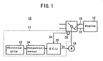
- FIG. 1 shows a functional block diagram of a vehicle 10 on which an engine output controller 11 according to an embodiment of the present invention is mounted.
- the vehicle 10 is a motorcycle, and the vehicle 10 has an engine 12.
- An intake passage 14 connected to the engine 12 is equipped therein with a throttle valve 16 for controlling the quantity of air supplied into the engine 12.
- the throttle valve 16 is attached to a return spring (not shown), which energized (biases) the throttle valve 16 in the direction for closing the throttle valve 16.
- a motor 18 is connected to the throttle valve 16 through a gearing (not shown), whereby the opening of the throttle valve 16 can be regulated.
- the motor 18 is controlled by an electronic control unit (ECU) 20.
- ECU electronice control unit
- the opening TH [degrees] of the throttle valve 16 is determined according to the rotation amount ROT [degrees] of a throttle grip 22 provided at a steering handle part of the vehicle 10, and the rotation amount ROT is detected by a potentiometer 24 connected to the throttle grip 22.
- the value detected by the potentiometer 24 is transmitted to the ECU 20, and the ECU 20 outputs a control signal Sc according to the detected value to the motor 18.
- the opening TH of the throttle valve 16 regulated by the motor 18 is detected by a throttle valve opening sensor 26, and the detected value is transmitted as an opening information signal So to the ECU 20.
- the engine output controller 11 includes the ECU 20, the throttle grip 22, the potentiometer 24 and the throttle valve opening sensor 26.
- FIG. 2 shows a flowchart for regulating the opening of the throttle valve 16.
- step S1 when the throttle grip 22 is rotated by the driver in the condition where the engine 12 has been started, the rotation amount ROT [degrees] is detected by the potentiometer 24.
- step S2 the ECU 20 judges a target opening DTHR [degrees] of the throttle valve 16, based on the value detected by the potentiometer 24.
- the target opening DTHR is a target value for the actual opening DTH [degrees] indicating the opening relative to a default opening THDEF [degrees] (for example, 5 degrees) of the throttle valve 16.
- step S3 the ECU 20 calculates a duty ratio DUT [%] for the control signal Sc to be outputted to the motor 18, and, in step S4, the ECU 20 transmits to the motor 18 the control signal Sc at the duty ratio DUT according to the results of the calculation executed in step S3.
- the duty ratio DUT of the control signal Sc varied according to the calculation results, the output of the motor 18 is controlled.
- the control signal Sc contains both signals for turning ON the motor 18 and signals for turning OFF the motor 18, and the presence ratio between the ON signals and the OFF signals within a fixed time is the duty ratio DUT.
- the duty ratio DUT is 60%. A specific method of calculating the duty ratio DUT will be described later.
- step S5 the motor 18, upon receiving the control signal Sc from the ECU 20, regulates the opening of the throttle valve 16 through an output according to the duty ratio DUT.
- air in a quantity according the actual opening DTH of the throttle valve 16 is supplied into the engine 12, and a fuel in an amount according to the quantity of the air is injected into the engine 12, whereby the output of the engine 12 is controlled.
- steps S1 to S5 are repeated until the engine 12 is stopped.
- the target opening DTHR for the throttle valve 16 is determined according to the rotation amount ROT of the throttle grip 22.
- the target opening DTHR can be determined in proportion to a pulse output from the potentiometer 24.
- the target opening DTHR may be determined by any of the methods described in the patent documents.
- Ueq[k] is equivalent control output
- Urch[k] is reaching output
- Udamp[k] is damping output
- Udutgap[k] is hysteresis compensation output
- a1, a2, b1, and c1 are model parameters determining the characteristics of a controlled system model (refer to Patent Document 1, paragraph [0027], etc.).
- VPOLE is a switching function setting parameter which is set as larger than -1 as well as smaller than 1 (refer to Patent Document 1, paragraphs [0030], [0035], [0037], [0038], etc.).
- the equivalent control output Ueq is an output for converging the erroneous deviation e between the actual opening DTH of the throttle valve 16 and the target opening DTHR to zero and constraining it on a switching straight line when the switching function value ⁇ is zero, and the equivalent control output Ueq is defined by the following formula (4):
- Ueq k 1 - a ⁇ 1 - VPOLE ⁇ DTH k + VPOLE - a ⁇ 2 ⁇ DTH ⁇ k - 1 + KDDTHR ⁇ ( DTHR k - DTHR ⁇ k - 1 ) 2 - c ⁇ 1 ⁇ 1 / b ⁇ 1
- the term "KDDTHR ⁇ (DTHR[k] - DTHR[k-1]) 2 " (hereinafter, the term as a whole will be referred to also as “the add-in amount x to the duty ratio DUT" or "the add-in amount x”) in the right-hand side is a term characteristic of the present invention, and will be detailed below.
- the coefficient "KDDTHR” represents a positive coefficient (in this embodiment, it is “1”).
- the coefficient "(DTHR[k] - DTHR[k-1]) 2" is the square of the difference between the current target opening DTHR[k] and the last target opening DTHR[k-1].
- the graph of the add-in amount x is a positive quadratic curve of which the vertex coincides with the origin, and the absolute value of the inclination of a tangent to the curve increases as the point of contact comes away from the origin. Therefore, in the region where the axis of abscissas is positive, the increment in the equivalent control output Ueq[k] (the add-in amount x to the duty ratio DUT) increases with an increase in the difference between the current target opening DTHR[k] and the last target opening DTHR[k-1] (namely, in the speed variation ⁇ DTHR [degrees/sec] of the target opening DTHR).
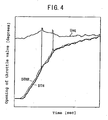
- FIG. 4 shows the target opening DTHR, the actual opening DTH and the equivalent control output Ueq when the vehicle 10 is accelerated.
- Points a and b in FIG. 4 correspond to points a and b in FIG. 3 .
- the speed variation ⁇ DTHR of the target opening DTHR is greater at point a than at point b.
- the equivalent control output Ueq corresponding to point a is greater than the equivalent control output Ueq corresponding to point b.
- the increment in the add-in amount x (the equivalent control output Ueq[k]) to the duty ratio DUT increases with an increase in the difference between the current target opening DTHR[k] and the last target opening DTHR[k-1]. Therefore, when the vehicle 10 is rapidly decelerated, the reduction in the duty ratio DUT is comparatively moderate. Accordingly, the minus torque exerted on the motor 18 at the time of rapid deceleration of the vehicle 10 is reduced by an amount corresponding to the add-in amount x, whereby the closing speed of the throttle valve 16 is lowered, resulting in that the output of the engine 12 can be reduced moderately.
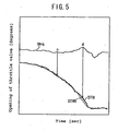
- FIG. 5 shows the target opening DTHR, the actual opening DTH and the equivalent control output Ueq when the vehicle 10 is decelerated.
- Points c and d in FIG. 5 correspond to points c and d in FIG. 3 .
- the speed variation ⁇ DTHR of the target opening DTHR is smaller at point d than at point c (the absolute value of the speed variation ⁇ DTHR is greater at point d).
- the equivalent control output Ueq corresponding to point d is greater than the equivalent control output Ueq corresponding to point c.
- Urch is an output for constraining the switching function value ⁇ to zero, and is defined by the following formula (5):
- Urch k - F / b ⁇ 1 ⁇ ⁇ k
- This formula (5) is like the formula (9a) in Patent Document 1, and detailed description thereof is omitted here.
- the damping output Udamp is an output for preventing the actual opening DTH from overshooting the target opening DTHR, and is defined by the following formula (6):
- Udamp k - Kdamp ⁇ ⁇ k - ⁇ ⁇ k - 1 / b ⁇ 1
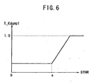
- the gain characteristic value T_Kdump1 is a positive gain characteristic value which is enlarged when the target opening DTHR of the throttle valve 16 exceeds a positive predetermined value s. Since the gain characteristic value T_Kdump2 has a positive value as described later and the gain characteristic value Kdamp is multiplied by -1 (refer to the formula (6)), the gain characteristic value T_Kdump1 is enlarged in the plus direction when the opening of the throttle valve 16 is enlarged, and, as a result, the damping output Udamp is enlarged in the minus direction. Therefore, by use of the gain characteristic value T_Kdump1, it is possible to prevent the overshoot upon rapid acceleration of the vehicle 10.
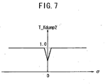
- the gain characteristic value T_Kdump2 is a positive gain characteristic value which is reduced when the switching function value ⁇ is in the vicinity of zero. Since the gain characteristic value T_Kdump1 has a positive value as described above and the gain characteristic value Kdamp is multiplied by -1, the gain characteristic value T_Kdump2 is enlarged when the switching function value ⁇ has a value far from zero, with the result that the value of the damping output Udamp is enlarged.
- the switching function value ⁇ has a value far from zero, i.e., when the robust property is small, the absolute value of the damping output Udamp can be made to be large, whereby the switching function value ⁇ can be brought close to the switching straight line, thereby enhancing the robust property.
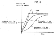
- FIG. 8 shows a diagram for comparing the target opening DTHR with the actual opening DTH obtained by use of the damping output Udamp based on the formula (6) and the actual opening DTH obtained by use of the damping outputs Udamp based on the formula (25) and the formula (27) in Patent Document 1.
- the actual opening DTH obtained by use of the damping output Udamp based on the formula (25) in Patent Document 1 overshoots the target opening DTHR.
- the actual opening DTH obtained by use of the damping output Udamp based on the formula (6) hereinabove realizes a higher-speed follow-up performance, as compared with the actual opening DTH obtained by use of the damping output Udamp based on the formula (27) in Patent Document 1.
- the hysteresis compensation output Udutgap is an output obtained by taking into account the hysteresis in regulation of the opening of the throttle valve 16, and is defined by the following formula (8):
- Udutgap k DUTR DTH k - Ueq k + Urch k + Udamp k ⁇ Kdut / b ⁇ 1
- DUTR(DTH[k]) is the value of the duty ratio DUT necessary for operating the throttle valve 16 according to the value of the actual opening DTH[k].
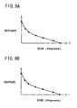
- Kdut includes a coefficient KDUTGAPH and a coefficient KDUTGAPL, and these coefficients KDUTGAPH and KDUTGAPL are functions of the target opening DTHR, as shown in FIGS. 9A and 9B .
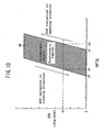
- Regulation of the opening of the throttle valve 16 by the motor 18 involves a hysteresis characteristic as shown in FIG. 10 .
- the motor 18 does not perform the regulation of the opening.
- the throttle valve 16 starts operating in the opening direction at the time when the duty ratio DUT of the control signal Sc sent from the ECU 20 to the motor 18 is d1 [%].
- the throttle valve 16 returns to its initial position at the time when the duty ratio DUT is d2 [%], which is smaller than d1.
- the duty ratio DUT must be d3 [degrees] in order to operate the throttle valve 16 in the opening direction.
- the duty ratio DUT is d4 (which is smaller than d3) in order to operate the throttle valve 16 in the closing direction.
- the main factors which are considered to cause the above-mentioned hysteresis characteristics include a factor intrinsic of the motor, friction in the mechanical system, and energization by the return spring.
- the factor intrinsic of the motor is the current value at which the motor starts operating, and the current value varies depending on such factors as the positions, shapes, materials and the like of the winding, the core and the like.
- the friction in the mechanical system includes the friction between the shaft of the motor and the bearing, and the friction between the plurality of gears in the motor.
- the energization by the return spring is the energization of the throttle valve in the closing direction by the return spring connected to the throttle valve.
- the hysteresis characteristic as shown in FIG. 10 appears when the duty ratio DUT [%] is varied in a fixed manner, and another hysteresis characteristic appears when the variation in the duty ratio DUT is varied.
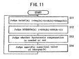
- FIG. 11 shows a flowchart for judging the hysteresis compensation output Udutgap[k].
- step S13 the ECU 20 judges whether the hydteresis compensation is needed or not.
- step S14 the ECU 20 judges a specific numerical value of the hysteresis compensation output Udutgap.
- step S13 it is judged whether the hysteresis compensation is needed or not.
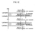
- the ECU 20 presets five regions (region 0 to region 5) for the difference ETHL[k] [degrees] between the target opening DTHR[k] and the actual opening DTH[k], and detects that one of the regions 0 to 5 in which the current difference ETHL lies, thereby judging whether the hysteresis compensation is needed or not.
- the difference ETHL is not less than a positive threshold C_DUTGAPHH (this condition is referred to as "region 0")
- region 0 a positive threshold C_DUTGAPHH
- the driver is wanting a very high engine output and that the actual opening DTH of the throttle valve 16 will soon come out of the hysteresis region 40 ( FIG. 10 ), and, therefore, the ECU 20 does not perform the hysteresis compensation.
- the threshold C_DUTGAPHH has one value at the time of an increase in the difference ETHL and another value at the time of a decrease in the difference ETHL.
- the threshold C_DUTGAPHH is set to be comparatively high for the time when the difference ETHL increases, and the threshold C_DUTGAPHH is set to be comparatively low for the time when the difference ETHL decreases.
- the difference between the higher value and the lower value is represented by C_HYSDTGPH.
- the ECU 20 judges that the engine output cannot be obtained due to the hysteresis notwithstanding the driver is wanting a moderate acceleration, and basically performs a hysteresis compensation such as to increase the duty ratio DUT of the control signal Sc.
- the ECU 20 judges that the opening of the throttle valve 16 has not changed, and does not perform any hysteresis compensation.
- the ECU 20 judges that the engine output would be enlarged due to the hysteresis notwithstanding the driver is wanting a moderate deceleration, and performs a hysteresis compensation such as to reduce the duty ratio DUT of the control signal Sc.
- the threshold C_DUTGAPLL has one value at the time of an increase in the difference ETHL and another value at the time of a decrease in the difference ETHL. Specifically, the threshold C_DUTGAPLL is set to be comparatively low (enlarged in the minus direction) for the time when the difference ETHL increases (varies in the minus direction), and the threshold C_DUTGAPLL is set to be comparatively high (reduced in the minus direction) for the time when the difference ETHL decreases (varies in the positive direction).
- the difference between the higher value and the lower value is represented by C_HYSDTGPL.
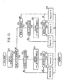
- FIG. 13 shows a flowchart for a process in the above-mentioned step S13 (a process for judging regions 0 to 5 in FIG. 12 ).
- step S22 the ECU 20 judges whether or not the difference ETHL[k] is larger than the positive threshold C_DUTGAPHL (see FIG. 12 ) which is for judging whether a movement in the opening direction made by the throttle valve 16 is intended or not.
- step S23 is entered, whereas in the case where the difference ETHL[k] is not more than the threshold C_DUTGAPHL, step S28 is entered.
- step S23 the ECU 20 judges whether or not the difference ETHL[k] is smaller than the positive threshold C_DUTGAPHH which is for judging whether or not the throttle valve 16 actually moves in the opening direction.
- step S24 is entered, and the ECU 20 judges that the movement in the opening direction made by the throttle valve 16 is so large that no hysteresis compensation is needed, in other words, the difference ETHL lies in region 0 in FIG. 12 and no hysteresis compensation is needed.
- step S25 is entered.
- step S25 the ECU 20 judges a target duty ratio DUTTGTH [%] necessary for actually moving the throttle valve 16 in the opening direction, according to the target opening DTHR.
- the target duty ratio DUTTGTH is preliminarily stored in a memory (not shown) on the basis of each target opening DTHR.
- step S24 is entered, and the ECU 20 judges that the target duty ratio DUTTGTH is in region 0 outside the hysteresis region 40 and that no hysteresis compensation is needed.
- step S27 is entered, and the ECU 20 judges that the target duty ratio DUTTGTH is in region 1 inside the hysteresis region 40 and that a hysteresis compensation is needed.
- step S28 is entered.
- step S28 the ECU 20 judges whether or not the difference ETHL[k] is larger than the threshold C_DUTGAPLL, in order to judge whether or not the movement in the closing direction made by the throttle valve 16 needs a hysteresis compensation.
- step S29 is entered, and the ECU 20 judges that the movement in the closing direction made by the throttle valve 16 is so large as not to need any hysteresis compensation, in other words, the difference ETHL is in region 4 in FIG. 12 and no hysteresis compensation is needed.
- step S30 is entered.
- step S30 the ECU 20 judges whether or not the difference ETHL is less than the threshold C_DUTGAPLH. In the case where the difference ETHL is not less than the threshold C_DUTGAPLH, step S31 is entered, and it is judged that the current situation is region 2. Where the difference ETHL is less than the threshold C_DUTGAPLH, step S32 is entered.
- step S32 the ECU 20 judges a target duty ratio DUTTGTL [%] necessary for actually moving the throttle valve 16 in the closing direction, according to the target opening DTHR.
- the target duty ratio DUTTGTL is preliminarily stored in a memory (not shown) on the basis of each target opening DTHR.
- step S29 is entered, and the ECU 20 judges that the target duty ratio DUTTGTL is in region 4 outside the hysteresis region 40 and that no hysteresis compensation is needed.
- step S34 is entered, and the ECU 20 judges that the target duty ratio DUTTGTL is in region 3 inside the hysteresis region 40 and that a hysteresis compensation is needed.
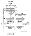
- FIG. 14 shows a flowchart for the ECU 20 to judge the specific numerical value of the hysteresis compensation output Udutgap[k].
- step S41 the ECU 20 judges the moving direction of the throttle valve 16. Specifically, the ECU 20 judges the moving direction of the throttle valve 16 by detecting whether the speed variation DTGDDRTHR [degrees/sec] of the target opening DTH is positive or negative. Or, alternatively, in consideration of an error, instead of simply detecting whether the speed variation DTGDDRTHR is positive or negative, the moving direction of the throttle valve 16 may be judged according to whether or not the speed variation DTGDDRTHR exceeds each of a positive predetermined value and a negative predetermined which are preliminarily set.
- step S42 it is judged whether or not the speed variation DTGDDTH [degrees/sec] of the actual opening DTH is larger than a negative threshold C_DGTPOUTL [degrees/sec].
- the negative threshold C_DGTPOUTL is for judging whether a hysteresis compensation is needed or not in the case of a closing operation of the throttle valve 16.
- step S43 is entered, and the hysteresis compensation output Udutgap[k] is set to zero.
- step S44 is entered.
- step S44 like in step S43, it is judged whether or not the speed variation DTGDDTH of the actual opening DTH is larger than a positive threshold C_DGTPOUTH.
- step S43 is entered, and the hysteresis compensation output Udutgap[k] is set to zero.
- step S45 is entered.
- step S45 the ECU 20 judges whether or not the difference ETHL is in region 1. In the case where the difference ETHL is in region 1, step S46 is entered; on the other hand, where the difference ETHL is not in region 1, step S49 is entered.
- step S47 the ECU 20 reads a coefficient KDUTGAPH from a preset table T_KDUTGAPH.
- the coefficient KDUTGAPH is included in the above-mentiioned function Kdut, and has the characteristic as shown in FIG. 9A .
- the coefficient KDUTGAPH has such a characteristic that it decreases with an increase in the target opening DTHR of the throttle valve 16.
- step S48 the ECU 20 calculates a hysteresis compensation output Udutgap by use of the following formula (9):
- Udutgap k KDUTGAPH DTHR k ⁇ DUTTGTH k - USLBF k
- step S45 In the case where it is judged in step S45 that the difference ETHL is not in region 1, it is judged in step S49 whether or not the difference ETHL is in region 3. Where the difference ETHL is not in region 3, step S50 is entered, in which Udutgap[k] is set to zero. Where the difference ETHL is in region 3, step S51 is entered.
- step S50 is entered, in which the hysteresis compensation output Udutgap is set to zero.
- step S52 is entered.
- step S52 the ECU 20 reads a coefficient KDUTGAPL from a preset table.
- the coefficient KDUTGAPL is included in the above-mentioned function Kdut, and has a characteristic as shown in FIG. 9B .
- the coefficient KDUTGAPL has such a characteristic as to decrease with a decrease in the target DTHR of the throttle valve 16.
- FIG. 9B the positive/negative sense of the axis of abscissas is reversed.
- step S53 the ECU 20 calculates the hysteresis compensation output Udutgap by use of the following formula (10):
- Udutgap k KDUTGAPL DTHR k ⁇ DUTTGTL k - USLBF k
- the ECU 20 performs both the process of increasing the output of the motor 18 by increasing the add-in amount x to the duty ratio DUT of the control signal Sc according to the increase in the speed variation ⁇ DTHR of the target opening DTHR when the speed variation ⁇ DTHR is positive and the process of decreasing the output of the motor 18 by increasing the add-in amount x to the duty ratio DUT of the control signal Sc according to the decrease in the speed variation ⁇ DTHR when the speed variation ⁇ DTHR is negative.
- the ECU 20 determines the add-in amount x to the duty ratio DUT of the control signal Sc in each of the two processes by use of a positive quadratic function of the speed variation ⁇ DTHR.
- a positive quadratic function of the speed variation ⁇ DTHR In the graph of a positive quadratic function, the absolute value of the inclination of a tangent thereto is increased as the point of contact comes away from the vertex of the graph. Therefore, when the speed variation ⁇ DTHR is near zero, i.e., when a moderate acceleration or deceleration is being conducted, it is possible to slowly increase or decrease the actual opening DTH of the throttle valve 16 and, as a result, to slowly increase or decrease the engine output, so that the drivability of the vehicle 10 is enhanced.
- the present invention is not limited to the above-described embodiment, and various configurations can naturally be adopted based on the contents of the present specification.
- the configurations as described in the following (1) to (5) can be adopted.
- the vehicle 10 has been a motorcycle in the above-described embodiment, this is not limitative.
- the vehicle may be a four-wheel vehicle.
- throttle grip 22 has been used as a means for inputting the target opening DTHR in the above-described embodiment, this is not limitative.
- an accelerator pedal may also be used as the input means.
- throttle grip 22 and the potentiometer 24 have been described as separate elements in the above-described embodiment, they may be of an integral form.
- a sliding mode control has been used as a control method in the above-described embodiment, this is not limitative.
- a nonlinear robust control other than the sliding mode control or a linear robust control may also be used.
- the output of the motor 18 can be varied also by modifying other output characteristic than the duty ratio DUT.
- the output of the motor 18 can also be varied by varying the number of pulses, the amplitude or the frequency of the control signal Sc.
- a part of the equivalent control output Ueq has been determined by use of a quadratic function in the above-described embodiment, this is not limitative, and use may be made of any technique that varies the output characteristic of the control signal Sc according to the speed variation ⁇ DTHR of the target opening DTHR.
- the output of the control signal Sc can be varied also by use of a linear function.
- a linear function with a positive inclination is adopted when the speed variation ⁇ DTHR of the target opening DTHR takes a positive value
- a linear function with a negative inclination is adopted when the speed variation ⁇ DTHR takes a negative value.
- the opening TH may also be used.
- the invention is directed to a driving amount controller in which it is possible to reduce a response delay or erroneous deviation in control of a driving amount of a controlled system, such as control of the opening of a throttle valve.
- An ECU 20 on a vehicle 10 increases an add-in amount x to the duty ratio DUT of a control signal Sc according to an increase in the speed variation ⁇ DTHR of a target opening DTRH of the throttle valve 16 when the speed variation ⁇ DTHR is positive. Besides, the ECU 20 increases the add-in amount x to the duty ratio DUT of the control signal Sc according to a decrease in the speed variation ⁇ DTHR when the speed variation ⁇ DTHR is negative.
Landscapes
- Engineering & Computer Science (AREA)
- Evolutionary Computation (AREA)
- Medical Informatics (AREA)
- Mechanical Engineering (AREA)
- General Engineering & Computer Science (AREA)
- Health & Medical Sciences (AREA)
- Artificial Intelligence (AREA)
- Combustion & Propulsion (AREA)
- Chemical & Material Sciences (AREA)
- Computer Vision & Pattern Recognition (AREA)
- Software Systems (AREA)
- Physics & Mathematics (AREA)
- General Physics & Mathematics (AREA)
- Automation & Control Theory (AREA)
- Control Of Throttle Valves Provided In The Intake System Or In The Exhaust System (AREA)
- Electrical Control Of Air Or Fuel Supplied To Internal-Combustion Engine (AREA)
Claims (2)
- Antriebsbetragregler (11) zum Regeln eines Antriebsbetrags eines geregelten Systems (16) durch eine Ausgabe eines Motors (18), umfassend:ein Soll-Antriebsbetrag-Eingabemittel (22) zum Eingeben eines Soll-Antriebsbetrags (DTHR) für das geregelte System (16); undein Regelmittel (20) zum Übertragen eines Regelsignals (Sc) auf den Motor (18) zum Regeln der Ausgabe des Motors (18) mit einer Ausgabescharakteristik gemäß dem Soll-Antriebsbetrag (DTHR),worin das Regelmittel (20) einen Prozess des Erhöhens der Ausgabe des Motors (18) durch Verändern der Ausgabecharakteristik des Regelsignals (Sc) gemäß einer Zunahme in der Drehzahländerung (ΔDTHR) des Soll-Antriebsbetrags (DTHR), wenn die Drehzahländerung positiv ist, und/oder einen Prozess des Verringerns der Ausgabe des Motors (18) durch Verändern der Ausgabecharakteristik des Regelsignals (Sc) gemäß einer Abnahme in der Drehzahländerung, wenn die Drehzahländerung negativ ist, durchführt,dadurch gekennzeichnet, dass das Regelmittel (20) dazu ausgelegt ist, zu einem Tastverhältnis (DUT) des Regelsignals (Sc) einen Additionsbetrag (x) zu addieren,worin der Graph des Additionsbetrags (x) eine positive quadratische Kurve ist, deren Scheitel mit dem Ursprung übereinstimmt, undworin der Additionsbetrag (x) mit zunehmender Drehzahländerung (ΔDTHR) des Soll-Antriebsbetrags (DTHR), wenn die Drehzahländerung (ΔDTHR) positiv ist, oder mit abnehmender Drehzahländerung (ΔDTHR), wenn die Drehzahländerung (ΔDTHR) negativ ist, zunimmt.
- Der Antriebsbetragregler (11) nach Anspruch 1, worin das geregelte System (16) ein Drosselventil (16) ist und der Antriebsbetrag die Öffnung des Drosselventils (16) ist.
Applications Claiming Priority (1)
| Application Number | Priority Date | Filing Date | Title |
|---|---|---|---|
| JP2007095466A JP4705602B2 (ja) | 2007-03-30 | 2007-03-30 | 駆動量制御装置 |
Publications (2)
| Publication Number | Publication Date |
|---|---|
| EP1975390A1 EP1975390A1 (de) | 2008-10-01 |
| EP1975390B1 true EP1975390B1 (de) | 2011-12-07 |
Family
ID=39597530
Family Applications (1)
| Application Number | Title | Priority Date | Filing Date |
|---|---|---|---|
| EP08004735A Active EP1975390B1 (de) | 2007-03-30 | 2008-03-13 | Steuerung der Antriebsstärke |
Country Status (5)
| Country | Link |
|---|---|
| US (1) | US7702448B2 (de) |
| EP (1) | EP1975390B1 (de) |
| JP (1) | JP4705602B2 (de) |
| CN (1) | CN101276204B (de) |
| ES (1) | ES2375228T3 (de) |
Families Citing this family (4)
| Publication number | Priority date | Publication date | Assignee | Title |
|---|---|---|---|---|
| US8175766B2 (en) * | 2009-06-25 | 2012-05-08 | Brammo, Inc. | Throttle control method and system |
| DE102010000744A1 (de) * | 2010-01-08 | 2011-07-14 | Robert Bosch GmbH, 70469 | Verfahren zum Regeln der durch eine Reibung gehemmten Bewegung eines Bauteils oder Maschinenelements |
| JP6026198B2 (ja) | 2012-09-25 | 2016-11-16 | 株式会社ケーヒン | 電子制御装置 |
| CN107463098B (zh) * | 2017-09-29 | 2020-07-31 | 中南林业科技大学 | 一种基于二次函数的智能小车速度控制方法和装置 |
Family Cites Families (22)
| Publication number | Priority date | Publication date | Assignee | Title |
|---|---|---|---|---|
| US4597049A (en) * | 1982-12-28 | 1986-06-24 | Nissan Motor Company, Limited | Accelerator control system for automotive vehicle |
| JPS61106934A (ja) * | 1984-10-30 | 1986-05-24 | Mazda Motor Corp | エンジンのスロツトル弁制御装置 |
| US5189621A (en) * | 1987-05-06 | 1993-02-23 | Hitachi, Ltd. | Electronic engine control apparatus |
| US5056613A (en) * | 1990-07-27 | 1991-10-15 | Ford Motor Company | Vehicular speed control system with reduced gear chatter |
| US5420793A (en) * | 1991-08-09 | 1995-05-30 | Ford Motor Company | Vehicle speed control system with quadratic feedback control |
| JP3073591B2 (ja) * | 1992-03-17 | 2000-08-07 | マツダ株式会社 | エンジンの制御装置 |
| JPH0688543A (ja) * | 1992-09-04 | 1994-03-29 | Nippondenso Co Ltd | スロットル制御装置 |
| JP3003408B2 (ja) * | 1992-09-09 | 2000-01-31 | 三菱電機株式会社 | エンジンのスロットル弁装置 |
| JP3489251B2 (ja) * | 1995-03-28 | 2004-01-19 | 株式会社デンソー | 内燃機関のスロットル制御装置 |
| JPH09317538A (ja) * | 1996-05-23 | 1997-12-09 | Aisin Seiki Co Ltd | スロットルバルブ制御装置 |
| JPH11235072A (ja) * | 1998-02-18 | 1999-08-27 | Sharp Corp | 回転速度制御方法 |
| JPH11270364A (ja) * | 1998-03-23 | 1999-10-05 | Denso Corp | 内燃機関のスロットル制御装置 |
| EP1203874A4 (de) * | 1999-07-28 | 2008-07-30 | Hitachi Ltd | Verfahren und vorrichtung für ein motorbetriebenes drosselventil, fahrzeug, verfahren zur messung der motortemperatur zum steuern des drosselventils und verfahren zur messung der motortemperatur |
| JP3701600B2 (ja) * | 2001-11-09 | 2005-09-28 | 本田技研工業株式会社 | プラントの制御装置 |
| JP3686377B2 (ja) * | 2002-01-23 | 2005-08-24 | 本田技研工業株式会社 | プラントの制御装置 |
| JP4002460B2 (ja) * | 2002-03-26 | 2007-10-31 | 本田技研工業株式会社 | スロットル弁駆動装置の制御装置 |
| JP3977199B2 (ja) * | 2002-08-22 | 2007-09-19 | 本田技研工業株式会社 | スロットル弁駆動装置の制御装置 |
| US6718255B1 (en) * | 2002-10-04 | 2004-04-06 | Ford Global Technologies, Llc | Method and system for matching engine torque transitions between closed and partially closed accelerator pedal positions |
| DE10335732A1 (de) * | 2003-08-05 | 2005-02-24 | Daimlerchrysler Ag | Verfahren zum Ändern des Beschleunigungsmodus eines Kraftfahrzeugs |
| JP2005180391A (ja) * | 2003-12-22 | 2005-07-07 | Nissan Diesel Motor Co Ltd | 内燃機関の制御装置 |
| JP2005301661A (ja) * | 2004-04-12 | 2005-10-27 | Toyota Motor Corp | 出力可変システムの制御装置 |
| JP2006307797A (ja) * | 2005-05-02 | 2006-11-09 | Yamaha Motor Co Ltd | 鞍乗型車両のエンジン制御装置及びエンジン制御方法 |
-
2007
- 2007-03-30 JP JP2007095466A patent/JP4705602B2/ja not_active Expired - Fee Related
-
2008
- 2008-02-27 CN CN2008100741728A patent/CN101276204B/zh not_active Expired - Fee Related
- 2008-03-13 EP EP08004735A patent/EP1975390B1/de active Active
- 2008-03-13 ES ES08004735T patent/ES2375228T3/es active Active
- 2008-03-27 US US12/057,227 patent/US7702448B2/en active Active
Also Published As
| Publication number | Publication date |
|---|---|
| JP2008255789A (ja) | 2008-10-23 |
| US7702448B2 (en) | 2010-04-20 |
| US20080243357A1 (en) | 2008-10-02 |
| ES2375228T3 (es) | 2012-02-27 |
| JP4705602B2 (ja) | 2011-06-22 |
| EP1975390A1 (de) | 2008-10-01 |
| CN101276204B (zh) | 2010-12-22 |
| CN101276204A (zh) | 2008-10-01 |
Similar Documents
| Publication | Publication Date | Title |
|---|---|---|
| US8150555B2 (en) | Fluid pressure control apparatus/process | |
| US8260521B2 (en) | Vehicle drive force control system | |
| EP1975390B1 (de) | Steuerung der Antriebsstärke | |
| US5719768A (en) | Lock-up clutch control method | |
| US20030028262A1 (en) | Control system for throttle valve actuating device | |
| US6766785B2 (en) | Electronic throttle control apparatus | |
| US6817338B2 (en) | Idle speed control system | |
| CN100564921C (zh) | 用于接合离合器注油水平和容量的学习方法 | |
| US6523522B1 (en) | Method and apparatus for operating a throttle plate motor driving a throttle plate having opposing return springs | |
| EP1975391B1 (de) | Vorrichtung zur regelung der Leistung einer Brennkraftmaschine | |
| CN115126610A (zh) | 节流阀的电子控制方法及电子控制节流阀装置 | |
| US6449553B1 (en) | Motor vehicle control device with regulation and/or limitation of driving speed | |
| EP2239443B1 (de) | Elektronische Drosselklappensteuerung | |
| EP1975392B1 (de) | Steuerung der Antriebsstärke | |
| CN101292102A (zh) | 车辆的驱动力控制设备 | |
| US11999348B2 (en) | Adaptive brake mode selection | |
| US11085532B2 (en) | Method for controlling a hydraulic system | |
| US20030062024A1 (en) | Control system for throttle valve actuating device | |
| JP2010077821A (ja) | 電子ガバナの制御方法及びその制御装置 | |
| JP3041156B2 (ja) | 内燃機関の絞り弁制御装置 | |
| JPH07243526A (ja) | トルクコンバータのロックアップ制御装置 |
Legal Events
| Date | Code | Title | Description |
|---|---|---|---|
| PUAI | Public reference made under article 153(3) epc to a published international application that has entered the european phase |
Free format text: ORIGINAL CODE: 0009012 |
|
| 17P | Request for examination filed |
Effective date: 20080313 |
|
| AK | Designated contracting states |
Kind code of ref document: A1 Designated state(s): AT BE BG CH CY CZ DE DK EE ES FI FR GB GR HR HU IE IS IT LI LT LU LV MC MT NL NO PL PT RO SE SI SK TR |
|
| AX | Request for extension of the european patent |
Extension state: AL BA MK RS |
|
| AKX | Designation fees paid |
Designated state(s): DE ES IT |
|
| GRAP | Despatch of communication of intention to grant a patent |
Free format text: ORIGINAL CODE: EPIDOSNIGR1 |
|
| GRAS | Grant fee paid |
Free format text: ORIGINAL CODE: EPIDOSNIGR3 |
|
| GRAA | (expected) grant |
Free format text: ORIGINAL CODE: 0009210 |
|
| RIN1 | Information on inventor provided before grant (corrected) |
Inventor name: ASADA, YUKIHIRO Inventor name: TSUYUGUCHI, MAKOTO Inventor name: TAKEDA, TORU |
|
| AK | Designated contracting states |
Kind code of ref document: B1 Designated state(s): DE ES IT |
|
| RAP1 | Party data changed (applicant data changed or rights of an application transferred) |
Owner name: HONDA MOTOR CO., LTD. |
|
| REG | Reference to a national code |
Ref country code: DE Ref legal event code: R096 Ref document number: 602008011801 Country of ref document: DE Effective date: 20120202 |
|
| REG | Reference to a national code |
Ref country code: ES Ref legal event code: FG2A Ref document number: 2375228 Country of ref document: ES Kind code of ref document: T3 Effective date: 20120227 |
|
| PLBE | No opposition filed within time limit |
Free format text: ORIGINAL CODE: 0009261 |
|
| STAA | Information on the status of an ep patent application or granted ep patent |
Free format text: STATUS: NO OPPOSITION FILED WITHIN TIME LIMIT |
|
| 26N | No opposition filed |
Effective date: 20120910 |
|
| REG | Reference to a national code |
Ref country code: DE Ref legal event code: R097 Ref document number: 602008011801 Country of ref document: DE Effective date: 20120910 |
|
| REG | Reference to a national code |
Ref country code: DE Ref legal event code: R084 Ref document number: 602008011801 Country of ref document: DE |
|
| PGFP | Annual fee paid to national office [announced via postgrant information from national office to epo] |
Ref country code: IT Payment date: 20180321 Year of fee payment: 11 |
|
| PGFP | Annual fee paid to national office [announced via postgrant information from national office to epo] |
Ref country code: ES Payment date: 20180402 Year of fee payment: 11 |
|
| PG25 | Lapsed in a contracting state [announced via postgrant information from national office to epo] |
Ref country code: IT Free format text: LAPSE BECAUSE OF NON-PAYMENT OF DUE FEES Effective date: 20190313 |
|
| REG | Reference to a national code |
Ref country code: ES Ref legal event code: FD2A Effective date: 20200724 |
|
| PG25 | Lapsed in a contracting state [announced via postgrant information from national office to epo] |
Ref country code: ES Free format text: LAPSE BECAUSE OF NON-PAYMENT OF DUE FEES Effective date: 20190314 |
|
| PGFP | Annual fee paid to national office [announced via postgrant information from national office to epo] |
Ref country code: DE Payment date: 20240220 Year of fee payment: 17 |