EP1975362A2 - Isolierleiste für ein wärmegedämmtes Verbundprofil für Türen, Fenster oder Fassaden - Google Patents
Isolierleiste für ein wärmegedämmtes Verbundprofil für Türen, Fenster oder Fassaden Download PDFInfo
- Publication number
- EP1975362A2 EP1975362A2 EP08100062A EP08100062A EP1975362A2 EP 1975362 A2 EP1975362 A2 EP 1975362A2 EP 08100062 A EP08100062 A EP 08100062A EP 08100062 A EP08100062 A EP 08100062A EP 1975362 A2 EP1975362 A2 EP 1975362A2
- Authority
- EP
- European Patent Office
- Prior art keywords
- webs
- insulating strip
- isolierleistenteile
- strip according
- insulating
- Prior art date
- Legal status (The legal status is an assumption and is not a legal conclusion. Google has not performed a legal analysis and makes no representation as to the accuracy of the status listed.)
- Granted
Links
- 239000002131 composite material Substances 0.000 title claims abstract description 21
- 239000002184 metal Substances 0.000 claims abstract description 12
- 239000000463 material Substances 0.000 description 3
- 238000004080 punching Methods 0.000 description 3
- 238000005452 bending Methods 0.000 description 2
- 230000008602 contraction Effects 0.000 description 2
- 238000010438 heat treatment Methods 0.000 description 2
- 238000010276 construction Methods 0.000 description 1
- 230000001419 dependent effect Effects 0.000 description 1
- 238000006073 displacement reaction Methods 0.000 description 1
- 230000000694 effects Effects 0.000 description 1
- 230000005489 elastic deformation Effects 0.000 description 1
- 239000006260 foam Substances 0.000 description 1
- 239000011888 foil Substances 0.000 description 1
- 239000012212 insulator Substances 0.000 description 1
- 238000004519 manufacturing process Methods 0.000 description 1
- 230000007704 transition Effects 0.000 description 1
- 230000000007 visual effect Effects 0.000 description 1
Images


Classifications
-
- E—FIXED CONSTRUCTIONS
- E06—DOORS, WINDOWS, SHUTTERS, OR ROLLER BLINDS IN GENERAL; LADDERS
- E06B—FIXED OR MOVABLE CLOSURES FOR OPENINGS IN BUILDINGS, VEHICLES, FENCES OR LIKE ENCLOSURES IN GENERAL, e.g. DOORS, WINDOWS, BLINDS, GATES
- E06B3/00—Window sashes, door leaves, or like elements for closing wall or like openings; Layout of fixed or moving closures, e.g. windows in wall or like openings; Features of rigidly-mounted outer frames relating to the mounting of wing frames
- E06B3/04—Wing frames not characterised by the manner of movement
- E06B3/263—Frames with special provision for insulation
- E06B3/26301—Frames with special provision for insulation with prefabricated insulating strips between two metal section members
-
- E—FIXED CONSTRUCTIONS
- E06—DOORS, WINDOWS, SHUTTERS, OR ROLLER BLINDS IN GENERAL; LADDERS
- E06B—FIXED OR MOVABLE CLOSURES FOR OPENINGS IN BUILDINGS, VEHICLES, FENCES OR LIKE ENCLOSURES IN GENERAL, e.g. DOORS, WINDOWS, BLINDS, GATES
- E06B3/00—Window sashes, door leaves, or like elements for closing wall or like openings; Layout of fixed or moving closures, e.g. windows in wall or like openings; Features of rigidly-mounted outer frames relating to the mounting of wing frames
- E06B3/04—Wing frames not characterised by the manner of movement
- E06B3/263—Frames with special provision for insulation
- E06B3/26301—Frames with special provision for insulation with prefabricated insulating strips between two metal section members
- E06B3/26305—Connection details
- E06B2003/26314—Provisions for reducing the shift between the strips and the metal section members
-
- E—FIXED CONSTRUCTIONS
- E06—DOORS, WINDOWS, SHUTTERS, OR ROLLER BLINDS IN GENERAL; LADDERS
- E06B—FIXED OR MOVABLE CLOSURES FOR OPENINGS IN BUILDINGS, VEHICLES, FENCES OR LIKE ENCLOSURES IN GENERAL, e.g. DOORS, WINDOWS, BLINDS, GATES
- E06B3/00—Window sashes, door leaves, or like elements for closing wall or like openings; Layout of fixed or moving closures, e.g. windows in wall or like openings; Features of rigidly-mounted outer frames relating to the mounting of wing frames
- E06B3/04—Wing frames not characterised by the manner of movement
- E06B3/263—Frames with special provision for insulation
- E06B2003/26349—Details of insulating strips
- E06B2003/2635—Specific form characteristics
- E06B2003/26361—Openings, incisions or indents
Definitions
- the invention relates to an insulating strip for a thermally insulated composite profile for doors, windows or facades according to the preamble of claim 1.
- Such a composite profile is from the EP 0 829 609 B1 known.
- the known composite profile consists of metal profiles and at least one arranged between the metal profiles and shear-resistant connected to the metal profiles on the longitudinal edges, preferably made of plastic insulating strip, wherein the insulating strip has two Isolierelfnmaschine.
- a central connection between the two Isolierangn spirits is designed as a sliding guide.
- the sliding guide between the two Isolierankn costumes ensures that caused by heating of the composite profile partCloudnausdehnungsunter Kunststoffe not lead to an unduly high deflection of the composite profile.
- the DE 198 53 235 A1 proposes a thermally insulated composite profile with an insulating strip, which in turn has two Isolierangnmaschine connected to the metal profiles, wherein the insulating strip between the Isolierangn really has a region of increased elasticity, for example, by another material or by elastic Webs should be realized.
- This solution has the disadvantage that the low elasticity of the material used for insulating strips in the proposed constructions usually does not allow to ensure the required relative mobility of Isolierangnener each other.
- the invention is based on the described prior art, the object to provide alternative, easy to manufacture insulating strips for thermally insulated composite profiles, with which it as with the solution of EP 0 829 609 B1 or the DE 199 56 415 C1 it is possible to prevent that by heating the thermally insulated composite profile an impermissible high deflection of the composite profile may occur.
- the invention solves this problem by the subject matter of claim 1.
- the invention further provides a thermally insulated composite profile with such an insulating profile or with such an insulating strip.
- the webs ensure a relative movement of Isolierangnmaschine relative to each other, which is realized by joints on the webs. This is advantageous because in such a simple way a sufficiently large relative displacement is achieved, which is problematic in the other case - according to the prior art - if the webs are to act elastically over their entire length and overcome the restoring forces from the elastic deformation These restoring forces implement a tension that, albeit reduced, leads to bending deformation of the insulating strip.
- the webs are designed so stiff that no changes in length of the webs occur. They are resistant to pressure and tension.
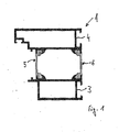
- FIG. 1 shows a section through an exemplary thermally insulated composite profile 1, which is purely exemplary of a window frame of a window suitable.
- the composite profile 1 has metal profiles 3, 4, which are connected by way of example by two insulating strips or webs 5, 6 together.
- the insulating strips 5, 6, according to the FIG. 1 the metal profiles 2, 3 interconnect, have several Isolierelfnmaschine or Isolierelfnteilabête.
- the insulating strips 5 of FIG. 2 a first Isolierelfnteil 7 which engages in the mounted state with a guide arm in the one metal profile
- the insulating strip 5 also has a second Isolierolinnteil 8, which engages with a further guide arm in the second metal section 4.
- the two Isolieranknmaschine 7, 8 of the insulating strip 5 are connected via a plurality of webs 10, 11 here cohesively with each other.
- the two Isolierelfnmaschine 7, 8 of the insulating strip 5 are preferably designed to be continuous axially in their main extension direction.
- the webs 10, 11 are configured such that the two Isolierancenmaschine 7, 8 of the insulating strip 5 are limited relative to each other movable, such that adjacent webs 10, 11- here from the rectangular shape of Fig. 2 - in a parallelogram form - Fig. 3 - be moved.
- each web must be connected in its opposite end portions each have a hinge 9 with the Isolierelfn matter 7, 8.
- the joints 9 can be designed in various ways, so as a film-joint-like thin material connections between the webs 10, 11 and the Isolierelfn really or Isolierelfnteilabêten 7, 8 ( Fig. 2 ; Webs 10 and 11) or journal / Lageraugekonstrutationen with separate webs 19, 24, which are hinged to the Isolierelfnmaschine or Isolierelfnteilabête 7, 8 ( Fig. 6 . 7 ).
- the webs 10, 11 can be generated for example by punching.
- FIGS. 2 and 3 two different types of webs 10, 11 shown.
- a web 10 which is thicker in the middle and outwardly thinner (almost trapezoidal) is designed so that its hinge portions act on the Isolierelfnmaschine itself as joints 9, so that it is possible, the one Isolierangnteil 7 relative to the other Isolierangnteil. 8 to move, with the webs 10 pivot parallelogram ( FIG. 3 ).
- the webs 11 have a greater width over most of their length and are connected to the insulating strip parts 7, 8 via constrictions or film-hinge-like constrictions 12, 13 only in the region of the transitions to the insulating strip parts 7, 8, so that the insulating strip parts 7 , 8 are movable relative to each other.
- the constrictions 12, 13 act here as film hinge-like joints 9, so that the webs 11 in turn turn parallelogram-like in a heat-induced deflection ( FIG. 3 ).
- the webs 10, 11 extend as transverse webs perpendicular to the longitudinal axis or to the axial axis of the insulating strip, because in this case, the transverse contraction of the insulating strip ( FIG. 3 ), no matter in which direction, only small. However, the transverse contraction is so small in the practical case that it can be neglected in the assembled state with regard to their effects.
- the webs should also be relatively long or the Isolierangnmaschine 7, 8 as short as possible, so as to give the largest possible swing radius.
- FIG. 4 and FIG. 5 It is possible to make a visual veneering of the punch-outs 14 between the webs 10, 11. This blindfold can take place by means of one or more foils 15, 16, which are applied to the forming webs 10, 11 for one or both sides of the insulating bars after punching out of the insulating strips or engage in grooves 2 in the insulating strip parts 7, 8
- the condition is that the Isolierangnmaschine 7, 8 are each configured or have recesses 21, that the pivotal movement of the webs 19 is not hindered.
- FIGS. 6c and 6d illustrate that on the webs 15 side cover plates 20 may be applied or formed on this, which in turn constitute a privacy screen or a cover for the recesses 21.
- the Isolierelfnmaschine 7, 8 are no longer integrally connected to each other, but they still form a total insulating strip or provide Isolierangnmaschine an overarching insulating strip.
- FIG. 6e illustrates a further variant, according to which the boom 17 itself may in turn preferably have outwardly open recesses 22 which form the boom 17 elastic to allow easy clipping of the boom 17 in the recesses 18.
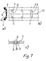
- FIG. 7 shows a further embodiment of the invention, in which the Isolierancenmaschine 7, 8 are separated by a narrow gap 25 from each other. At the Isolierancenmaschine 7, 8 webs 24 are articulated.
- This articulation is preferably done in a simple manner by means of pins.
- pins are here designed as a spreader pin 26 having a head and squeeze feet 28.
- the head can also be sort of Fig. 7c one piece or cohesively with the web 24 (or with the Isolierelfnteil 7, 8) be configured or formed directly from the webs 24.
- the pin 26 is inserted through a bore 29 of the Isolierelfnteils 7, so that it spreads when he passes through this completely. This type of assembly is particularly easy.
- the Spreekapfen can also be configured separately and for mounting through corresponding through holes of the superimposed webs 24 and the Isolierangnmaschine 7, 8 are pushed through, with the feet 28 widen again after passing through the two holes.
Landscapes
- Engineering & Computer Science (AREA)
- Civil Engineering (AREA)
- Structural Engineering (AREA)
- Wing Frames And Configurations (AREA)
- Special Wing (AREA)
Abstract
Description
- Die Erfindung betrifft eine Isolierleiste für ein wärmegedämmtes Verbundprofil für Türen, Fenster oder Fassaden nach dem Oberbegriff des Anspruchs 1.
- Ein derartiges Verbundprofil ist aus der
EP 0 829 609 B1 bekannt. Das bekannte Verbundprofil besteht aus Metallprofilen und mindestens einer zwischen den Metallprofilen angeordneten und mit den Metallprofilen an den Längskanten schubfest verbundenen, vorzugsweise aus Kunststoff gefertigten Isolierleiste, wobei die Isolierleiste zwei Isolierleistenteile aufweist. Eine mittige Verbindung zwischen den zwei Isolierleistenteilen ist als Gleitführung ausgeführt. Die Gleitführung zwischen den zwei Isolierleistenteilen stellt sicher, dass durch Erwärmung des Verbundprofilteils bedingte Längenausdehnungsunterschiede nicht zu einer unzulässig hohen Durchbiegung des Verbundprofils führen können. - Die Idee der Gleitführung wird in der
DE 199 56 415 C1 wieder aufgegriffen, wobei die Relativverschieblichkeit, die durch die Gleitführung realisiert wird, nach den Maßnahmen dieser Schrift auf einen vorgegebenen Weg begrenzt wird. Dies wird mittels einer federsteifen Außenbrücke erreicht, welche die Isolierleistenteile miteinander stoffschlüssig oder nicht stoffschlüssig verbindet. - Die
DE 198 53 235 A1 schlägt ein wärmegedämmtes Verbundprofil mit einer Isolierleiste vor, die wiederum zwei mit den Metallprofilen verbundene Isolierleistenteile auf weist, wobei die Isolierleiste zwischen den Isolierleistenteilen einen Bereich erhöhter Elastizität aufweist, der beispielsweise durch ein anderes Material oder durch elastische Stege realisiert werden soll. Diese Lösung hat den Nachteil, dass es die geringe Elastizität des für Isolierleisten verwendeten Materials bei den vorgeschlagenen Konstruktionen in der Regel nicht zulässt, die geforderte Relativbeweglichkeit der Isolierleistenteile zueinander sicherzustellen. - Der Erfindung liegt ausgehend von dem beschriebenen Stand der Technik die Aufgabe zugrunde, alternative, möglichst einfach zu fertigende Isolierleisten für wärmegedämmte Verbundprofile zu schaffen, mit denen es wie mit der Lösung der
EP 0 829 609 B1 oder derDE 199 56 415 C1 möglich ist, zu verhindern, dass durch Erwärmung des wärmegedämmten Verbundprofils eine unzulässige hohe Durchbiegung des Verbundprofils auftreten kann. - Die Erfindung löst diese Aufgabe durch den Gegenstand des Anspruchs 1. Die Erfindung schafft ferner ein wärmegedämmtes Verbundprofil mit einem derartigen Isolierprofil bzw. mit einer derartigen Isolierleiste.
- Bei allen Ausführungsbeispielen stellen die Stege eine Relativbewegung der Isolierleistenteile relativ zueinander sicher, was durch Gelenke an den Stegen realisiert wird. Dies ist vorteilhaft, da derart auf einfache Weise eine genügend große Relativverschiebung erreicht wird, was im anderen Fall - nach dem Stand der Technik - problematisch ist, wenn die Stege in sich über ihre gesamte Länge elastisch wirken sollen und die Rückstellkräfte aus der elastischen Verformung überwinden müssen, wobei diese Rückstellkräfte eine Spannung implementieren, die, wenn auch verringert, zur Biegeverformung der Isolierleiste führt.
- Auftretende thermische Längenänderungen der Profilschalen der Verbundprofile werden durch das parallelogrammartige Verschwenken der Stege ausgeglichen bzw. nicht behindert, so dass Spannungen vermieden werden, die zu einem unerwünschten Durchbiegen des Verbundprofils führen könnten.
- Im montierten Zustand der Verbundprofile wird vorzugsweise jeweils ein schubfester Verbund zwischen den einzelnen Isolierleistenteilen und den zugehörigen Metallprofilen realisiert.
- Temperaturschwankungen werden durch die parallelogrammartige Bewegung gem.
Figur 3 ausgeglichen. Relativbewegungen zwischen den Isolierleistenteilen sind vorzugsweise in einem Bereich zwischen 2 mm und 10 mm, insbesondere in einem Bereich zwischen 2 mm und 6 mm möglich. - Die Stege sind derart steif ausgestaltet, dass keine Längenveränderungen der Stege auftreten. Sie sind druck- und zugstabil.
- Vorteilhafte Ausgestaltungen der Erfindung sind den Unteransprüchen zu entnehmen.
- Nachfolgend wird die Erfindung anhand von Ausführungsbeispielen unter Bezug auf die Zeichnung näher beschrieben. Es zeigt:
- Figur 1
- einen Schnitt durch ein erfindungsgemäßes Verbundprofil;
- Figur 2a, b
- zwei verschiedene Ansichten einer ersten erfindungsgemäßen Isolierleiste;
- Figur 3
- die Isolierleiste aus
Fig. 2 im ausgelenkten Zustand; - Fig. 4,5
- Schnitte durch mit Sichtverblendungen versehene erfindungsgemäße Isolierleisten;
- Figur 6a-e
- verschiedene Ansichten, Ausschnitte und Varianten einer dritten erfindungsgemäßen Isolierleiste und
- Figur 7a bis 7c
- verschiedene Ansichten und Ausschnitte einer vierten erfindungsgemäßen Isolierleiste.
-
Figur 1 zeigt einen Schnitt durch ein beispielhaftes wärmegedämmtes Verbundprofil 1, das rein beispielhaft für einen Blendrahmen eines Fensters geeignet ist. - Das Verbundprofil 1 weist Metallprofile 3, 4 auf, die hier beispielhaft durch zwei Isolierleisten bzw. -stege 5, 6 miteinander verbunden sind.
- Die Isolierleisten 5, 6, die entsprechend der
Figur 1 die Metallprofile 2, 3 miteinander verbinden, weisen mehrere Isolierleistenteile bzw. Isolierleistenteilabschnitte auf. - So weisen die Isolierleisten 5 der
Figur 2 einen ersten Isolierleistenteil 7 auf, der im montierten Zustand mit einem Führungsausleger in das eine Metallprofil 3 eingreift. - Die Isolierleiste 5 weist ferner einen zweiten Isolierleistenteil 8 auf, der mit einem weiteren Führungsausleger in das zweite Metallprofil 4 eingreift.
- Die beiden Isolierleistenteile 7, 8 der Isolierleiste 5 sind über mehrere Stege 10, 11 hier stoffschlüssig miteinander verbunden.
- Die beiden Isolierleistenteile 7, 8 der Isolierleiste 5 sind axial in ihrer Haupterstreckungsrichtung vorzugsweise durchgehend ausgebildet.
- Die Stege 10, 11 sind derart ausgestaltet, dass die beiden Isolierleistenteile 7, 8 der Isolierleiste 5 begrenzt relativ zueinander beweglich sind, derart, dass zueinander benachbarte Stege 10, 11- hier aus der Rechteckform der
Fig. 2 - in eine Parallelogrammform -Fig. 3 - bewegt werden. Dazu muß jeder Steg in seinen voneinander abgewandten Endbereichen jeweils über ein Gelenk 9 mit den Isolierleistenteilen 7, 8 verbunden sein. - Die Gelenke 9 können auf verschiedene Weise ausgestaltet sein, so als filmgelenkartige dünne Materialanbindungen zwischen den Stegen 10, 11 und den Isolierleistenteilen bzw. Isolierleistenteilabschnitten 7, 8 (
Fig. 2 ; Stege 10 und 11) oder Zapfen/Lageraugekonstruktionen mit separaten Stegen 19, 24, welche an die Isolierleistenteile bzw. Isolierleistenteilabschnitte 7, 8 angelenkt sind (Fig. 6 ,7 ). - Dies sei nachstehend näher erläutert.
- Die Stege 10, 11 können beispielsweise durch ein Ausstanzen erzeugt werden.
- Rein beispielhaft sind in
Figur 2 und 3 zwei verschiedene Arten von Stegen 10, 11 dargestellt. - So zeigt die
Figur 2 einerseits einen Steg 10, der in der Mitte dicker und nach außen hin dünner (nahezu trapezartig) ausgestaltet ist, so dass seine Anlenkbereiche an die Isolierleistenteile selbst als Gelenke 9 wirken, so dass es möglich ist, den einen Isolierleistenteil 7 relativ zum anderen Isolierleistenteil 8 zu bewegen, wobei sich die Stege 10 parallelogrammartig verschwenken (Figur 3 ). - Die Stege 11 weisen dagegen über den größten Teil ihrer Länge eine größere Breite auf und sind lediglich im Bereich der Übergänge zu den Isolierleistenteilen 7, 8 über Einschnürungen bzw. filmscharnierartige Verengungen 12, 13 mit den Isolierleistenteilen 7, 8 verbunden, so dass die Isolierleistenteile 7, 8 relativ zueinander beweglich sind. Die Verengungen 12, 13 wirken hier als filmscharnierartige Gelenke 9, so dass sich die Stege 11 bei einem wärmebedingten Auslenken wiederum parallelogrammartig verschwenken (
Figur 3 ). - Optimal ist es, wenn sich die Stege 10, 11 als Querstege senkrecht zur Längsachse bzw. zur Axialachse der Isolierleiste erstrecken, denn in diesem Fall wirkt sich die Querkontraktion der Isolierleiste (
Figur 3 ), egal in welche Richtung, nur gering aus. Die Querkontraktion ist aber im praktischen Fall so klein, dass sie im montierten Zustand hinsichtlich ihrer Effekte vernachlässigt werden kann. - Die Stege sollten zudem relativ lang sein bzw. die Isolierleistenteile 7, 8 möglichst kurz, damit sich ein möglichst großer Schwenkradius ergibt.
- Gemäß
Figur 4 und Figur 5 ist es möglich, eine Sichtverblendung der Ausstanzungen 14 zwischen den Stegen 10, 11 vorzunehmen. Diese Sichtverblendung kann mittels einer oder mehrerer Folien 15, 16 erfolgen, die nach dem Ausstanzen der Isolierleisten zu bildender Stege 10, 11 für eine oder beide Seiten der Isolierstege aufgebracht werden oder in Nuten 2 in den Isolierleistenteilen 7, 8 eingreifen - Diese Folien müssen so dünn bzw. elastisch sein, dass die Bewegung der Isolierprofilteile 7, 8 relativ zueinander durch sie nicht verhindert wird.
- Es bietet sich daher an, eine schaumartige Masse zum Ausbilden der Folien 15, 16 zu verwenden.
- Denkbar ist es alternativ auch, die Ausstanzungen 14 direkt nach dem Ausstanzen mit einem Schaum auszufüllen und derart eine Sichtverblendung zu realisieren.
- Diese Maßnahmen sind auch bei den Ausführungen der
Fig. 6 und7 sinnvoll, die nachfolgend beschrieben werden. - Danach ist es auch denkbar, die Isolierleistenteile 7, 8 der Isolierleiste 5 vollständig voneinander zu trennen. Auf diese Weise wird eine mehrstückige Isolierleiste realisiert.
- Nach
Figur 6 weisen die Stege 19 zapfenartige Ausleger 17 auf, die in korrespondierend geformte, lageraugenartige Aussparungen 18 der Isolierleistenteile 7, 8 eingreifen, wobei durch die zapfenartigen Ausleger 17 in den Ausnehmungen 18 an beiden Seiten der Stege 19 die Beweglichkeit der Isolierleistenteile 7, 8 über zwei Gelenke 9 in eine Parallelogrammstellung nach Art derFig. 3 gewährleistet wird. - Voraussetzung ist, dass die Isolierleistenteile 7, 8 jeweils derart ausgestaltet sind bzw. Ausnehmungen 21 aufweisen, dass die Schwenkbewegung der Stege 19 nicht behindert wird.
- Die
Figuren 6c und 6d veranschaulichen, dass auf die Stege 15 seitliche Abdeckplatten 20 aufgebracht bzw. an diese angeformt sein können, welche wiederum einen Sichtschutz bzw. eine Abdeckung für die Ausnehmungen 21 darstellen. - Hier sind die Isolierleistenteile 7, 8 nicht mehr einstückig miteinander verbunden, sie bilden aber insgesamt immer noch eine Isolierleiste bzw. stellen Isolierleistenteile einer übergreifenden Isolierleiste dar.
-
Figur 6e veranschaulicht eine weitere Variante, nach der die Ausleger 17 selber wiederum vorzugsweise nach außen offene Aussparungen 22 aufweisen können, die den Ausleger 17 elastisch ausbilden, um ein einfaches Einklipsen der Ausleger 17 in die Ausnehmungen 18 zu ermöglichen. -
Figur 7 zeigt ein weiteres Ausführungsbeispiel der Erfindung, bei dem die Isolierleistenteile 7, 8 durch einen schmalen Spalt 25 voneinander getrennt sind. An die Isolierleistenteile 7, 8 sind Stege 24 angelenkt. - Dieses Anlenken erfolgt vorzugsweise auf einfache Weise mittels Zapfen.
- Diese Zapfen sind hier als Spreizzapfen 26 ausgebildet, die einen Kopf und zusammendrückbare Füße 28 aufweisen. Der Kopf kann auch nach Art der
Fig. 7c einstückig bzw. stoffschlüssig mit dem Steg 24 (oder mit dem Isolierleistenteil 7, 8) ausgestaltet sein bzw. direkt von den Stegen 24 gebildet werden. - Der Zapfen 26 wird durch eine Bohrung 29 des Isolierleistenteils 7 gesteckt, so dass er sich aufspreizt, wenn er dieses ganz durchsetzt. Diese Art der Montage ist besonders einfach.
- Der Spreizzapfen kann auch separat ausgestaltet sein und zur Montage durch korrespondierende Durchgangsbohrungen der aufeinander gelegten Stege 24 und der Isolierleistenteile 7, 8 durchgesteckt werden, wobei sich die Füße 28 nach dem Durchtritt durch die beiden Bohrungen wieder aufweiten.
-
- Verbundprofil
- 1
- Nuten
- 2
- Metallprofile
- 3,4
- Isolierleisten
- 5, 6
- Teile
- 7, 8
- Gelenk
- 9
- Stege
- 10, 11
- Verengungen
- 12, 13
- Ausstanzungen
- 14
- Folien
- 15, 16
- Ausleger
- 17
- Aussparungen
- 18
- Stege
- 19
- Abdeckplatten
- 20
- Ausnehmungen
- 21
- Aussparungen
- 22
- Spalt
- 25
- Stege
- 24
- Spreizzapfen
- 26
- Kopf
- 27
- Fuße
- 28
- Durchgangsbohrungen
- 29
Claims (17)
- Isolierleiste (5, 6) für ein wärmegedämmtes Verbundprofil eines Fensters, einer Tür oder einer Fassade, wobei die Isolierleiste wenigstens zwei oder mehrere relativ zueinander bewegliche Isolierleistenteile (7, 8) aufweist, welche über Stege (10, 11, 19, 24) miteinander verbunden sind, dadurch gekennzeichnet, dass die Stege (10, 11, 19, 24) derart ausgestaltet sind, dass die beiden Isolierleistenteile (7, 8) der Isolierleiste (5) begrenzt relativ zueinander derart beweglich sind, das zueinander benachbarte Stege (10, 11, 19, 24) und die Isolierleistenteile (7, 8) bei der Bewegung in eine Parallelogrammform verschwenkbar sind.
- Isolierleiste nach Anspruch 1, dadurch gekennzeichnet, dass zueinander benachbarte Stege (10, 11, 19, 24) und die Isolierleistenteile (7, 8) bei der Bewegung aus einer Rechteckform in die Parallelogrammform verschwenkbar sind.
- Isolierleiste nach Anspruch 1 oder 2, dadurch gekennzeichnet, dass die Stege (10, 11, 19, 24) in ihren voneinander abgewandten Endbereichen jeweils über ein Gelenk (9) oder einen gelenkartigen Bereich mit den Isolierleistenteilen (7, 8) verbunden sind.
- Isolierleiste nach Anspruch 3, dadurch gekennzeichnet, dass die Stege (10, 11, 19, 24) in ihren voneinander abgewandten Endbereichen jeweils über eine filmscharnierartige Verengung (12, 13) mit den Isolierleistenteilen (7, 8) verbunden sind.
- Isolierleiste nach Anspruch 3, dadurch gekennzeichnet, dass die Stege (10, 11, 19, 24) in ihren voneinander abgewandten Endbereichen jeweils über Achsausleger/Lageraugenanordnungen an die Isolierleistenteile (7, 8) angelenkt sind.
- Isolierleiste nach einem der vorstehenden Ansprüche, dadurch gekennzeichnet, dass sich die Stege (10, 11) im nicht ausgelenkten Zustand als Querstege senkrecht zur Längsachse bzw. zur Axialachse der Isolierleiste erstrecken.
- Isolierleiste nach einem der vorstehenden Ansprüche, dadurch gekennzeichnet, dass die Isolierleistenteile (7, 8) einstückig mit den Stegen (10, 11) ausgestaltet sind.
- Isolierleiste nach einem der vorstehenden Ansprüche, dadurch gekennzeichnet, dass die Stegen (10, 11) eine Trapezform aufweisen.
- Isolierleiste nach einem der vorstehenden Ansprüche, dadurch gekennzeichnet, dass die Isolierleiste mehrstückig ausgestaltet ist und dass die nicht materialschlüssig miteinander verbundenen Isolierleistenteile (7, 8) der mehrstückig ausgestalteten Isolierleiste mittels schwenkbar an die Isolierleistenteile (7, 8) angelenkter Stege (19, 24) miteinander verbunden sind.
- Isolierleiste nach einem der vorstehenden Ansprüche, dadurch gekennzeichnet, dass die Stege mit gelenkartigen Auslegern (17) in korrespondierende Ausnehmungen (18) der Isolierleistenteile (7, 8) eingreifen.
- Isolierleiste nach einem der vorstehenden Ansprüche, dadurch gekennzeichnet, dass die Stege Ausleger (17) aufweisen, die in Ausnehmungen (18) der Isolierleistenteile (7, 8) schwenkbar eingreifen.
- Isolierleiste nach einem der vorstehenden Ansprüche, dadurch gekennzeichnet, dass die Stege Ausleger (17) Aussparungen (22) aufweisen, so dass sie elastisch in die Ausnehmungen (18) der Isolierleistenteile (7, 8) einrastbar sind.
- Isolierleiste nach einem der vorstehenden Ansprüche, dadurch gekennzeichnet, dass die Stege (24) mittels Zapfen (26) an die Isolierleistenteile (7, 8) angelenkt sind, welche in Durchgangslöcher der Isolierleistenteile (7, 8) und der Stege (24) eingreifen.
- Isolierleiste nach einem der vorstehenden Ansprüche, dadurch gekennzeichnet, dass die Stege (24) mittels Zapfen (26) an die Isolierleistenteile (7, 8) angelenkt sind, welche in Durchgangslöcher der Isolierleistenteile (7, 8) eingreifen und stoffschlüssig mit den Stegen (24) ausgebildet sind.
- Isolierleiste nach einem der vorstehenden Ansprüche, dadurch gekennzeichnet, dass die Zapfen als Rastzapfen (26) ausgebildet sind.
- Isolierleiste nach einem der vorstehenden Ansprüche, gekennzeichnet durch wenigstens eine seitliche Sichtschutzabdeckung, insbesondere eine elastische Folie (15, 16) oder eine elastische Platte (20).
- Wärmegedämmtes Verbundprofil mit zwei Metallprofilen (3, 4) und wenigstens einer Isolierleiste (10, 11, 19, 24) nach einem der vorstehenden Ansprüche.
Applications Claiming Priority (1)
| Application Number | Priority Date | Filing Date | Title |
|---|---|---|---|
| DE200720004804 DE202007004804U1 (de) | 2007-03-30 | 2007-03-30 | Isolierleiste für ein wärmegedämmtes Verbundprofil für Türen, Fenster oder Fassaden |
Publications (3)
| Publication Number | Publication Date |
|---|---|
| EP1975362A2 true EP1975362A2 (de) | 2008-10-01 |
| EP1975362A3 EP1975362A3 (de) | 2013-05-08 |
| EP1975362B1 EP1975362B1 (de) | 2014-05-07 |
Family
ID=38190504
Family Applications (1)
| Application Number | Title | Priority Date | Filing Date |
|---|---|---|---|
| EP20080100062 Not-in-force EP1975362B1 (de) | 2007-03-30 | 2008-01-03 | Isolierleiste für ein wärmegedämmtes Verbundprofil für Türen, Fenster oder Fassaden |
Country Status (2)
| Country | Link |
|---|---|
| EP (1) | EP1975362B1 (de) |
| DE (1) | DE202007004804U1 (de) |
Cited By (1)
| Publication number | Priority date | Publication date | Assignee | Title |
|---|---|---|---|---|
| EP2530230A3 (de) * | 2011-05-30 | 2015-01-21 | Alcoa Aluminium Deutschland, Inc. | Isoliersteg für Fenster- und Türrahmen |
Families Citing this family (5)
| Publication number | Priority date | Publication date | Assignee | Title |
|---|---|---|---|---|
| DE102008064784B3 (de) | 2008-09-16 | 2019-05-23 | Hueck Gmbh & Co. Kg | Verbundprofil |
| DE102008047331C5 (de) | 2008-09-16 | 2016-09-08 | Hueck Gmbh & Co. Kg | Verfahren zur Herstellung eines Verbundprofils |
| DE202008012945U1 (de) | 2008-09-19 | 2008-12-18 | Ensinger Gmbh | Isoliersteg für Metall-Verbundprofile |
| IE86524B1 (en) * | 2009-07-15 | 2015-04-08 | Architectural & Metal Systems Ltd | Insulated frame member |
| DE102014106226A1 (de) | 2014-05-05 | 2015-11-05 | SCHÜCO International KG | Verbundprofil für Türen, Fenster oder Fassadenelemente |
Citations (3)
| Publication number | Priority date | Publication date | Assignee | Title |
|---|---|---|---|---|
| DE19853235A1 (de) | 1998-11-18 | 2000-05-25 | Wicona Bausysteme Gmbh | Wärmegedämmtes Verbundprofil, insbesondere für Fenster, Türen, Fassaden und dergleichen |
| DE19956415C1 (de) | 1999-11-24 | 2001-03-01 | Caprano & Brunnhofer | Isolierprofil für Türrahmen, Fensterrahmen oder dergleichen Verbundteile |
| EP0829609B1 (de) | 1996-09-17 | 2001-05-09 | SCHÜCO International KG | Wärmegedämmtes Verbundprofil für Türen, Fenster oder Fassaden |
Family Cites Families (1)
| Publication number | Priority date | Publication date | Assignee | Title |
|---|---|---|---|---|
| US4471589A (en) * | 1981-01-29 | 1984-09-18 | Eltreva Ag | Window or door |
-
2007
- 2007-03-30 DE DE200720004804 patent/DE202007004804U1/de not_active Expired - Lifetime
-
2008
- 2008-01-03 EP EP20080100062 patent/EP1975362B1/de not_active Not-in-force
Patent Citations (3)
| Publication number | Priority date | Publication date | Assignee | Title |
|---|---|---|---|---|
| EP0829609B1 (de) | 1996-09-17 | 2001-05-09 | SCHÜCO International KG | Wärmegedämmtes Verbundprofil für Türen, Fenster oder Fassaden |
| DE19853235A1 (de) | 1998-11-18 | 2000-05-25 | Wicona Bausysteme Gmbh | Wärmegedämmtes Verbundprofil, insbesondere für Fenster, Türen, Fassaden und dergleichen |
| DE19956415C1 (de) | 1999-11-24 | 2001-03-01 | Caprano & Brunnhofer | Isolierprofil für Türrahmen, Fensterrahmen oder dergleichen Verbundteile |
Cited By (1)
| Publication number | Priority date | Publication date | Assignee | Title |
|---|---|---|---|---|
| EP2530230A3 (de) * | 2011-05-30 | 2015-01-21 | Alcoa Aluminium Deutschland, Inc. | Isoliersteg für Fenster- und Türrahmen |
Also Published As
| Publication number | Publication date |
|---|---|
| EP1975362A3 (de) | 2013-05-08 |
| EP1975362B1 (de) | 2014-05-07 |
| DE202007004804U1 (de) | 2007-06-14 |
Similar Documents
| Publication | Publication Date | Title |
|---|---|---|
| EP2917076B1 (de) | Scheibenwischvorrichtung für ein fahrzeug | |
| EP3054192B1 (de) | Energieführungskette mit deformierbaren gelenkelementen | |
| EP1975362B1 (de) | Isolierleiste für ein wärmegedämmtes Verbundprofil für Türen, Fenster oder Fassaden | |
| EP1467910B1 (de) | Gelenk zur verbindung einer längsseite mit einer oberseite von bauteilen sowie flexibles band zur verwendung für ein derartiges gelenk | |
| WO2003062052A1 (de) | Gelenk zur verbindung von bauteilen mit einander zugewandten längsseiten sowie flexibles band zur verwendung für ein derartiges gelenk | |
| DE202011001104U1 (de) | Dichtungsvorrichtung mit einem Dichtungsprofil und einem Mechanismus zum Verschieben des Dichtungsprofils bei Betätigung des Mechanismus | |
| EP3124734B1 (de) | Verbindungsanordnung zum verbinden eines pfostens an einem rahmenprofil eines fensters oder einer türe aus kunststoff | |
| EP2090725A1 (de) | Steg zum Verbinden der beiden Zylinderhälften eines längenvariablen Doppelschliesszylinders | |
| EP1251236A2 (de) | Industrietor, doppelwandige Lamelle für ein Industrietor sowie Verfahren zur Herstellung einer derartigen Lamelle | |
| CH676376A5 (en) | Strip-type door-leaf seal | |
| EP1963711B1 (de) | Leitungsführungsanordnung mit verminderter geräuschemission | |
| DE202008000534U1 (de) | Profilschienensystem zum Abdecken mindestens eines Belagrandes | |
| EP2345786A2 (de) | Türband für Aluminiumtüren | |
| EP1242270B1 (de) | Wischarm | |
| AT517648B1 (de) | Scharnier | |
| EP1002924A2 (de) | Wärmegedämmtes Verbundprofil, insbesondere für Fenster, Türen, Fassaden und dergleichen | |
| DE102017101833A1 (de) | Fugenüberbrückungseinrichtung | |
| EP0737267A1 (de) | Rolladenstab | |
| DE202011050532U1 (de) | System mit einem Profil und einem Beschlagteil | |
| WO2012034970A1 (de) | Anordnung zur kabelführung | |
| EP3121356B1 (de) | Anordnung eines scharniers an einem hohlkammerprofil | |
| EP1644605B1 (de) | Verbundprofil mit isoliersteg, insbesondere für fenster, tür und fassaden | |
| EP2154324A2 (de) | Endstück mit Gelenkfunktion für Rolladenprofile und Rolladen | |
| EP1607538A2 (de) | Dichtungsprofil aus einem anorganischen Elastomer | |
| EP3115240A1 (de) | Dichtungspendelrpofil |
Legal Events
| Date | Code | Title | Description |
|---|---|---|---|
| PUAI | Public reference made under article 153(3) epc to a published international application that has entered the european phase |
Free format text: ORIGINAL CODE: 0009012 |
|
| AK | Designated contracting states |
Kind code of ref document: A2 Designated state(s): AT BE BG CH CY CZ DE DK EE ES FI FR GB GR HR HU IE IS IT LI LT LU LV MC MT NL NO PL PT RO SE SI SK TR |
|
| AX | Request for extension of the european patent |
Extension state: AL BA MK RS |
|
| PUAL | Search report despatched |
Free format text: ORIGINAL CODE: 0009013 |
|
| AK | Designated contracting states |
Kind code of ref document: A3 Designated state(s): AT BE BG CH CY CZ DE DK EE ES FI FR GB GR HR HU IE IS IT LI LT LU LV MC MT NL NO PL PT RO SE SI SK TR |
|
| AX | Request for extension of the european patent |
Extension state: AL BA MK RS |
|
| RIC1 | Information provided on ipc code assigned before grant |
Ipc: E06B 3/263 20060101AFI20130403BHEP |
|
| 17P | Request for examination filed |
Effective date: 20131025 |
|
| RBV | Designated contracting states (corrected) |
Designated state(s): AT BE BG CH CY CZ DE DK EE ES FI FR GB GR HR HU IE IS IT LI LT LU LV MC MT NL NO PL PT RO SE SI SK TR |
|
| AKX | Designation fees paid |
Designated state(s): AT BE BG CH CY CZ DE DK EE ES FI FR GB GR HR HU IE IS IT LI LT LU LV MC MT NL NO PL PT RO SE SI SK TR |
|
| GRAP | Despatch of communication of intention to grant a patent |
Free format text: ORIGINAL CODE: EPIDOSNIGR1 |
|
| INTG | Intention to grant announced |
Effective date: 20140131 |
|
| GRAS | Grant fee paid |
Free format text: ORIGINAL CODE: EPIDOSNIGR3 |
|
| GRAA | (expected) grant |
Free format text: ORIGINAL CODE: 0009210 |
|
| AK | Designated contracting states |
Kind code of ref document: B1 Designated state(s): AT BE BG CH CY CZ DE DK EE ES FI FR GB GR HR HU IE IS IT LI LT LU LV MC MT NL NO PL PT RO SE SI SK TR |
|
| REG | Reference to a national code |
Ref country code: GB Ref legal event code: FG4D Free format text: NOT ENGLISH |
|
| REG | Reference to a national code |
Ref country code: AT Ref legal event code: REF Ref document number: 666865 Country of ref document: AT Kind code of ref document: T Effective date: 20140515 |
|
| REG | Reference to a national code |
Ref country code: IE Ref legal event code: FG4D Free format text: LANGUAGE OF EP DOCUMENT: GERMAN |
|
| REG | Reference to a national code |
Ref country code: DE Ref legal event code: R096 Ref document number: 502008011708 Country of ref document: DE Effective date: 20140618 |
|
| REG | Reference to a national code |
Ref country code: NL Ref legal event code: VDEP Effective date: 20140507 |
|
| REG | Reference to a national code |
Ref country code: LT Ref legal event code: MG4D |
|
| PG25 | Lapsed in a contracting state [announced via postgrant information from national office to epo] |
Ref country code: CY Free format text: LAPSE BECAUSE OF FAILURE TO SUBMIT A TRANSLATION OF THE DESCRIPTION OR TO PAY THE FEE WITHIN THE PRESCRIBED TIME-LIMIT Effective date: 20140507 Ref country code: LT Free format text: LAPSE BECAUSE OF FAILURE TO SUBMIT A TRANSLATION OF THE DESCRIPTION OR TO PAY THE FEE WITHIN THE PRESCRIBED TIME-LIMIT Effective date: 20140507 Ref country code: IS Free format text: LAPSE BECAUSE OF FAILURE TO SUBMIT A TRANSLATION OF THE DESCRIPTION OR TO PAY THE FEE WITHIN THE PRESCRIBED TIME-LIMIT Effective date: 20140907 Ref country code: NO Free format text: LAPSE BECAUSE OF FAILURE TO SUBMIT A TRANSLATION OF THE DESCRIPTION OR TO PAY THE FEE WITHIN THE PRESCRIBED TIME-LIMIT Effective date: 20140807 Ref country code: FI Free format text: LAPSE BECAUSE OF FAILURE TO SUBMIT A TRANSLATION OF THE DESCRIPTION OR TO PAY THE FEE WITHIN THE PRESCRIBED TIME-LIMIT Effective date: 20140507 Ref country code: GR Free format text: LAPSE BECAUSE OF FAILURE TO SUBMIT A TRANSLATION OF THE DESCRIPTION OR TO PAY THE FEE WITHIN THE PRESCRIBED TIME-LIMIT Effective date: 20140808 |
|
| PG25 | Lapsed in a contracting state [announced via postgrant information from national office to epo] |
Ref country code: LV Free format text: LAPSE BECAUSE OF FAILURE TO SUBMIT A TRANSLATION OF THE DESCRIPTION OR TO PAY THE FEE WITHIN THE PRESCRIBED TIME-LIMIT Effective date: 20140507 Ref country code: ES Free format text: LAPSE BECAUSE OF FAILURE TO SUBMIT A TRANSLATION OF THE DESCRIPTION OR TO PAY THE FEE WITHIN THE PRESCRIBED TIME-LIMIT Effective date: 20140507 Ref country code: HR Free format text: LAPSE BECAUSE OF FAILURE TO SUBMIT A TRANSLATION OF THE DESCRIPTION OR TO PAY THE FEE WITHIN THE PRESCRIBED TIME-LIMIT Effective date: 20140507 Ref country code: PL Free format text: LAPSE BECAUSE OF FAILURE TO SUBMIT A TRANSLATION OF THE DESCRIPTION OR TO PAY THE FEE WITHIN THE PRESCRIBED TIME-LIMIT Effective date: 20140507 Ref country code: SE Free format text: LAPSE BECAUSE OF FAILURE TO SUBMIT A TRANSLATION OF THE DESCRIPTION OR TO PAY THE FEE WITHIN THE PRESCRIBED TIME-LIMIT Effective date: 20140507 |
|
| PG25 | Lapsed in a contracting state [announced via postgrant information from national office to epo] |
Ref country code: PT Free format text: LAPSE BECAUSE OF FAILURE TO SUBMIT A TRANSLATION OF THE DESCRIPTION OR TO PAY THE FEE WITHIN THE PRESCRIBED TIME-LIMIT Effective date: 20140908 |
|
| PG25 | Lapsed in a contracting state [announced via postgrant information from national office to epo] |
Ref country code: CZ Free format text: LAPSE BECAUSE OF FAILURE TO SUBMIT A TRANSLATION OF THE DESCRIPTION OR TO PAY THE FEE WITHIN THE PRESCRIBED TIME-LIMIT Effective date: 20140507 Ref country code: SK Free format text: LAPSE BECAUSE OF FAILURE TO SUBMIT A TRANSLATION OF THE DESCRIPTION OR TO PAY THE FEE WITHIN THE PRESCRIBED TIME-LIMIT Effective date: 20140507 Ref country code: DK Free format text: LAPSE BECAUSE OF FAILURE TO SUBMIT A TRANSLATION OF THE DESCRIPTION OR TO PAY THE FEE WITHIN THE PRESCRIBED TIME-LIMIT Effective date: 20140507 Ref country code: RO Free format text: LAPSE BECAUSE OF FAILURE TO SUBMIT A TRANSLATION OF THE DESCRIPTION OR TO PAY THE FEE WITHIN THE PRESCRIBED TIME-LIMIT Effective date: 20140507 Ref country code: EE Free format text: LAPSE BECAUSE OF FAILURE TO SUBMIT A TRANSLATION OF THE DESCRIPTION OR TO PAY THE FEE WITHIN THE PRESCRIBED TIME-LIMIT Effective date: 20140507 |
|
| REG | Reference to a national code |
Ref country code: DE Ref legal event code: R097 Ref document number: 502008011708 Country of ref document: DE |
|
| PG25 | Lapsed in a contracting state [announced via postgrant information from national office to epo] |
Ref country code: NL Free format text: LAPSE BECAUSE OF FAILURE TO SUBMIT A TRANSLATION OF THE DESCRIPTION OR TO PAY THE FEE WITHIN THE PRESCRIBED TIME-LIMIT Effective date: 20140507 |
|
| PLBE | No opposition filed within time limit |
Free format text: ORIGINAL CODE: 0009261 |
|
| STAA | Information on the status of an ep patent application or granted ep patent |
Free format text: STATUS: NO OPPOSITION FILED WITHIN TIME LIMIT |
|
| 26N | No opposition filed |
Effective date: 20150210 |
|
| PG25 | Lapsed in a contracting state [announced via postgrant information from national office to epo] |
Ref country code: IT Free format text: LAPSE BECAUSE OF FAILURE TO SUBMIT A TRANSLATION OF THE DESCRIPTION OR TO PAY THE FEE WITHIN THE PRESCRIBED TIME-LIMIT Effective date: 20140507 |
|
| REG | Reference to a national code |
Ref country code: DE Ref legal event code: R097 Ref document number: 502008011708 Country of ref document: DE Effective date: 20150210 |
|
| PG25 | Lapsed in a contracting state [announced via postgrant information from national office to epo] |
Ref country code: BE Free format text: LAPSE BECAUSE OF NON-PAYMENT OF DUE FEES Effective date: 20150131 |
|
| PG25 | Lapsed in a contracting state [announced via postgrant information from national office to epo] |
Ref country code: SI Free format text: LAPSE BECAUSE OF FAILURE TO SUBMIT A TRANSLATION OF THE DESCRIPTION OR TO PAY THE FEE WITHIN THE PRESCRIBED TIME-LIMIT Effective date: 20140507 |
|
| REG | Reference to a national code |
Ref country code: CH Ref legal event code: PL |
|
| PG25 | Lapsed in a contracting state [announced via postgrant information from national office to epo] |
Ref country code: LU Free format text: LAPSE BECAUSE OF FAILURE TO SUBMIT A TRANSLATION OF THE DESCRIPTION OR TO PAY THE FEE WITHIN THE PRESCRIBED TIME-LIMIT Effective date: 20150103 |
|
| PG25 | Lapsed in a contracting state [announced via postgrant information from national office to epo] |
Ref country code: MC Free format text: LAPSE BECAUSE OF FAILURE TO SUBMIT A TRANSLATION OF THE DESCRIPTION OR TO PAY THE FEE WITHIN THE PRESCRIBED TIME-LIMIT Effective date: 20140507 |
|
| PG25 | Lapsed in a contracting state [announced via postgrant information from national office to epo] |
Ref country code: CH Free format text: LAPSE BECAUSE OF NON-PAYMENT OF DUE FEES Effective date: 20150131 Ref country code: LI Free format text: LAPSE BECAUSE OF NON-PAYMENT OF DUE FEES Effective date: 20150131 |
|
| REG | Reference to a national code |
Ref country code: IE Ref legal event code: MM4A |
|
| REG | Reference to a national code |
Ref country code: FR Ref legal event code: PLFP Year of fee payment: 9 |
|
| PG25 | Lapsed in a contracting state [announced via postgrant information from national office to epo] |
Ref country code: IE Free format text: LAPSE BECAUSE OF NON-PAYMENT OF DUE FEES Effective date: 20150103 |
|
| REG | Reference to a national code |
Ref country code: AT Ref legal event code: MM01 Ref document number: 666865 Country of ref document: AT Kind code of ref document: T Effective date: 20150103 |
|
| PG25 | Lapsed in a contracting state [announced via postgrant information from national office to epo] |
Ref country code: AT Free format text: LAPSE BECAUSE OF NON-PAYMENT OF DUE FEES Effective date: 20150103 |
|
| PG25 | Lapsed in a contracting state [announced via postgrant information from national office to epo] |
Ref country code: MT Free format text: LAPSE BECAUSE OF FAILURE TO SUBMIT A TRANSLATION OF THE DESCRIPTION OR TO PAY THE FEE WITHIN THE PRESCRIBED TIME-LIMIT Effective date: 20140507 |
|
| REG | Reference to a national code |
Ref country code: FR Ref legal event code: PLFP Year of fee payment: 10 |
|
| PG25 | Lapsed in a contracting state [announced via postgrant information from national office to epo] |
Ref country code: HU Free format text: LAPSE BECAUSE OF FAILURE TO SUBMIT A TRANSLATION OF THE DESCRIPTION OR TO PAY THE FEE WITHIN THE PRESCRIBED TIME-LIMIT; INVALID AB INITIO Effective date: 20080103 Ref country code: BG Free format text: LAPSE BECAUSE OF FAILURE TO SUBMIT A TRANSLATION OF THE DESCRIPTION OR TO PAY THE FEE WITHIN THE PRESCRIBED TIME-LIMIT Effective date: 20140507 |
|
| PG25 | Lapsed in a contracting state [announced via postgrant information from national office to epo] |
Ref country code: TR Free format text: LAPSE BECAUSE OF FAILURE TO SUBMIT A TRANSLATION OF THE DESCRIPTION OR TO PAY THE FEE WITHIN THE PRESCRIBED TIME-LIMIT Effective date: 20140507 |
|
| REG | Reference to a national code |
Ref country code: FR Ref legal event code: PLFP Year of fee payment: 11 |
|
| PGFP | Annual fee paid to national office [announced via postgrant information from national office to epo] |
Ref country code: GB Payment date: 20180125 Year of fee payment: 11 |
|
| PGFP | Annual fee paid to national office [announced via postgrant information from national office to epo] |
Ref country code: FR Payment date: 20180124 Year of fee payment: 11 |
|
| GBPC | Gb: european patent ceased through non-payment of renewal fee |
Effective date: 20190103 |
|
| PG25 | Lapsed in a contracting state [announced via postgrant information from national office to epo] |
Ref country code: FR Free format text: LAPSE BECAUSE OF NON-PAYMENT OF DUE FEES Effective date: 20190131 |
|
| PG25 | Lapsed in a contracting state [announced via postgrant information from national office to epo] |
Ref country code: GB Free format text: LAPSE BECAUSE OF NON-PAYMENT OF DUE FEES Effective date: 20190103 |
|
| PGFP | Annual fee paid to national office [announced via postgrant information from national office to epo] |
Ref country code: DE Payment date: 20200205 Year of fee payment: 13 |
|
| REG | Reference to a national code |
Ref country code: DE Ref legal event code: R119 Ref document number: 502008011708 Country of ref document: DE |
|
| PG25 | Lapsed in a contracting state [announced via postgrant information from national office to epo] |
Ref country code: DE Free format text: LAPSE BECAUSE OF NON-PAYMENT OF DUE FEES Effective date: 20210803 |