EP1974852B1 - Vorrichtung zum Fixieren von Werkstücken auf einem Werktisch und zum Fördern zu Bearbeitungsstationen - Google Patents
Vorrichtung zum Fixieren von Werkstücken auf einem Werktisch und zum Fördern zu Bearbeitungsstationen Download PDFInfo
- Publication number
- EP1974852B1 EP1974852B1 EP07425189A EP07425189A EP1974852B1 EP 1974852 B1 EP1974852 B1 EP 1974852B1 EP 07425189 A EP07425189 A EP 07425189A EP 07425189 A EP07425189 A EP 07425189A EP 1974852 B1 EP1974852 B1 EP 1974852B1
- Authority
- EP
- European Patent Office
- Prior art keywords
- locating device
- belt
- wall
- workpiece
- contact
- Prior art date
- Legal status (The legal status is an assumption and is not a legal conclusion. Google has not performed a legal analysis and makes no representation as to the accuracy of the status listed.)
- Not-in-force
Links
- 238000003754 machining Methods 0.000 claims description 8
- 230000015572 biosynthetic process Effects 0.000 claims description 3
- 239000002184 metal Substances 0.000 claims description 3
- 239000002023 wood Substances 0.000 claims description 2
- 238000005520 cutting process Methods 0.000 description 2
- 238000003801 milling Methods 0.000 description 2
- 239000000463 material Substances 0.000 description 1
- 230000000284 resting effect Effects 0.000 description 1
- 238000003466 welding Methods 0.000 description 1
Images


Classifications
-
- B—PERFORMING OPERATIONS; TRANSPORTING
- B23—MACHINE TOOLS; METAL-WORKING NOT OTHERWISE PROVIDED FOR
- B23Q—DETAILS, COMPONENTS, OR ACCESSORIES FOR MACHINE TOOLS, e.g. ARRANGEMENTS FOR COPYING OR CONTROLLING; MACHINE TOOLS IN GENERAL CHARACTERISED BY THE CONSTRUCTION OF PARTICULAR DETAILS OR COMPONENTS; COMBINATIONS OR ASSOCIATIONS OF METAL-WORKING MACHINES, NOT DIRECTED TO A PARTICULAR RESULT
- B23Q7/00—Arrangements for handling work specially combined with or arranged in, or specially adapted for use in connection with, machine tools, e.g. for conveying, loading, positioning, discharging, sorting
- B23Q7/03—Arrangements for handling work specially combined with or arranged in, or specially adapted for use in connection with, machine tools, e.g. for conveying, loading, positioning, discharging, sorting by means of endless chain conveyors
- B23Q7/035—Arrangements for handling work specially combined with or arranged in, or specially adapted for use in connection with, machine tools, e.g. for conveying, loading, positioning, discharging, sorting by means of endless chain conveyors on which work holders are fixed
-
- B—PERFORMING OPERATIONS; TRANSPORTING
- B23—MACHINE TOOLS; METAL-WORKING NOT OTHERWISE PROVIDED FOR
- B23Q—DETAILS, COMPONENTS, OR ACCESSORIES FOR MACHINE TOOLS, e.g. ARRANGEMENTS FOR COPYING OR CONTROLLING; MACHINE TOOLS IN GENERAL CHARACTERISED BY THE CONSTRUCTION OF PARTICULAR DETAILS OR COMPONENTS; COMBINATIONS OR ASSOCIATIONS OF METAL-WORKING MACHINES, NOT DIRECTED TO A PARTICULAR RESULT
- B23Q7/00—Arrangements for handling work specially combined with or arranged in, or specially adapted for use in connection with, machine tools, e.g. for conveying, loading, positioning, discharging, sorting
- B23Q7/001—Lateral transport of long workpieces
Definitions
- the present invention relates to an apparatus for retaining workpieces with a mainly longitudinal extension on the work bench of a machine-tool and for feeding them from a loading position to positions where said parts undergo machining and then to a position for unloading from the bench, comprising at least one loader formed by a conveyor belt endlessly wound between two end pulleys, one of which is motor-driven, with the formation of a feeding portion which extends above said bench and a return section which extends below said bench, said belt including a plurality of locating devices fixed thereon in positions spaced from each other by a predetermined amount and projecting towards the outside of the endlessly wound belt.
- the workpieces on the bench are generally formed by profiled parts made of metal or plastic and also wood with widely varying cross-sections, transverse to their longitudinal axis, from tubular cross-sections with parallel sides to open cross-sections with sides at an angle relative to each other.
- these parts are deposited on a bench which is provided with means not only for retaining them in position, but also for moving them from a loading position into an unloading position, passing through one or more stations where machining operations are performed.
- machining operations may be of various types such as, for example, boring operations performed in predetermined points of the part or operations involving milling, cutting or mounting of accessories and so on.
- the means for fixing in position and feeding the workpieces on the bench comprise a plurality of loaders, each of which comprises a pair of endlessly wound belts which are tensioned between respective pairs of end pulleys with the formation of respective adjacent feeding portions which are parallel to each other and which extend above the bench and return sections which extend below the bench.
- Each belt of the pair, forming a loader has a plurality of fixed locating devices which project towards the outside of the associated endlessly wound belt and are spaced from each other at intervals of predetermined length.
- the alignment of the locating devices of one of the belts of the pair is modified with respect to the locating device of the other belt and consequently a seat is formed between one locating device of a belt and a locating device of the adjacent parallel belt with dimensions such as to keep clamped between them the cross-section of a component or profiled part to be machined, causing it to be fed forwards on the bench.
- the known loader mentioned above has the fundamental drawback that, in view of a given lag between the belts, the seats which are formed between the locating devices of one belt relative to those of the adjacent belt all have the same size along the whole feeding path of the belt.
- US 4,516,675 discloses a conveyor feed mechanism, particularly adapted for multiple cut saw machines wherein lumber is fed onto an endless conveyor.
- a dual-truck mechanism is attached to the endless conveyor chain, one of the trucks having an access seat and backstop for receiving and supporting lumber, and the other truck having a pivotal clamp held in a spring-biased position for clamping against the lumber.
- the object of the present invention is to overcome the drawback encountered in connection with the apparatus of the known art mentioned above by proposing an apparatus for retaining workpieces, in particular profiled parts, and feeding them on the work bench of an operating machine, even though the profiled parts have different cross-sections.
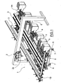
- 1 denotes overall the work bench of a conventional operating machine in the sector for the machining of metal, plastic or also wooden sections.
- This operating machine is provided with one or more workstations - schematically denoted by 2 - in which, for example, boring or milling as well as cutting or welding operations are performed on the sections 3 which are placed on the work bench and which are moved forwards in a direction which, for example, is perpendicular to the longitudinal extension of the bench 1 and also the parts 3.
- the workstations 2 in turn and in a conventional manner, may be mounted on a gantry situated above the work bench 1 so as to be able to be positioned wherever desired, with respect to the latter.
- the bench 1 in a conventional manner, consists of longitudinal bars 4 and transverse bars 5 which are connected together so as to form a rectangular frame which is supported by columns 6 provided with respective support feet 7 which can be adjusted heightwise.
- the bench 1 has, arranged on top of it, the apparatus for retaining the workpieces, in particular the sections 3, and for feeding them from a loading position 1A into an unloading position 1B passing through the position or positions for machining performed for example by the tool 2A of the operating head 2.
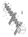
- This apparatus comprises a plurality of loaders, each denoted overall by 8 and shown in greater detail in Figure 2 and arranged perpendicularly with respect to the longitudinal bars 4 of the bench 1.
- Each loader in accordance with the invention, comprises a conveyor belt which is endlessly wound between two end pulleys 10 and 11, one of which is motor-driven.
- the motor-driven pulley is that indicated by 10 and situated in the position 1B for unloading the parts 3 from the bench 1. Said pulley receives its movement via the drive shaft 12 which is operated by a conventional stepper motor (not shown).
- each loader 8 forms a portion 13 which extends above the bench 1 and a return portion 14 which extends below the said bench.
- Each belt 9 has, fixed thereto, members for locating and clamping the workpieces 3. These locating members are denoted overall by 15 and are shown in greater detail in Figures 3 to 6 of the accompanying drawings.
- Each locating member 15 comprises a plate-shaped base 16 with side pieces 17 and 18 by means of which the base is fixed to the belt 9 so as to project towards the outside thereof.
- a wall 19 which projects towards the outside of the belt 9 is fixed to the base 16 and forms a wall for making contact with the workpieces 3, as will appear more clearly from the remainder of the description.
- a lever 20 is mounted on the base plate 16 by means of a pin 21 about which it is able to pivot in opposition to a spring 22 which, with its end 23, is secured to the fastening lug 24 of a flange 25 integral with the base 16, while with its opposite end 26 it is secured to the stud 27 mounted on the arm 28 of the lever 20 which extends perpendicularly with respect to the longitudinal axis of the latter.
- the free end of the lever 20 is equipped with a member 29 for resting against the workpiece 3.
- This member 29 extends in a direction parallel to the plane in which the fixed wall 19 is also situated and preferably has a cylindrical contour.
- the member 29 is mounted rotatably about its longitudinal axis A-A.
- the spring 22 keeps the lever 20 resiliently rotated so as to be offset at an angle with respect to the base 16 on which it is mounted, in the direction of the fixed wall 19 of the adjacent locating member 15 mounted on the said belt 9.
- each locating member 15 of each endlessly wound belt 9 is directed in a direction opposite to the direction of travel of the feeding portion of the belt 9 on the bench 1.
- each loader 8 has, positioned alongside it, a plate 30 with a cam profile 31 directed towards the edge of the advancing portion 13 of the belt 9.
- This cam profile comprises a first section 32, parallel to the direction of movement of the belt 9 and intended to remain in contact with a cam follower 33 mounted on the lever 20 and positioned on the arm 28 of the latter, on the opposite side to the stud 27 relative to the pivoting pin 21.
- the same cam profile 31 also comprises a section 34, also parallel to the feeding direction of the belt 9 and connected to the section 32 by means of a ramp 35, but positioned at a distance such as to be no longer engaged with the cam follower 33 when the latter is situated opposite it during the movement of the belt 9.
- the lever 20 is free, under the action of the spring 22, to move angularly within the section comprised between two adjacent locating members 15, positioning its free end 29 towards the plane in which the wall 19 of the locating member is situated, said wall, during movement of the belt 9, preceding it.
- Clamping of the part 3 is performed irrespective of the transverse dimensions and the geometrical configuration of its cross-section.
- the member 29 is mounted on the lever 20 rotatable with respect to its longitudinal axis A-A
- loading of a section 3, or more generally a workpiece, onto the bench 1 may be performed on the loaders 8 also when the lever 20 of each locating member 15, pushed by the spring 22, positions the member 29 so that it bears against the wall 19 of the adjacent locating device 15 which precedes it.
- the possibility of rotation of the member 29 about its longitudinal axis A-A allows the sliding movement of the section 3 against the member 29 and clamping thereof with respect to the wall 19 of the locating device 15 owing to the action of the spring 22 acting on the lever 20 of the said member 29.
- the plate 30 with the cam profile 31 is mounted on a slide (not shown in the figures) to which, in a conventional manner, it is fixed by means of screws 36.
- the slide can be actuated by means of fluid-dynamic actuating means 35, for example oil-dynamic or pneumatic means, in such a way that the plate 30 can assume adjustable positions relative to the belt 9.
- the plate 30 may be actuated so as to assume a position where the cam follower 33 associated with the lever 20 is disengaged from the cam profile 31 and consequently the lever 20 is pushed towards the plane in which the wall 19 for contact with the workpieces 3 is situated, with clamping thereof at the same time as positioning thereof in the loading position 1A of the bench 1.
- This operating mode of the loaders 8 is particularly useful when the cross-section of the profiled parts 3 has walls at an angle relative to each other, for example L-shaped or Z-shaped cross-sections.
Landscapes
- Engineering & Computer Science (AREA)
- Mechanical Engineering (AREA)
- Feeding Of Workpieces (AREA)
- Constituent Portions Of Griding Lathes, Driving, Sensing And Control (AREA)
- Multi-Process Working Machines And Systems (AREA)
- Automobile Manufacture Line, Endless Track Vehicle, Trailer (AREA)
- Structure Of Belt Conveyors (AREA)
Claims (8)
- Vorrichtung zum Fixieren von Werkstücken (3) mit einer hauptsächlich longitudinalen Ausdehnung auf dem Werktisch (1) einer Arbeitsmaschine und zum Zuführen von einer Ladeposition (1A) zu Positionen, wo die Werkstücke (3) einer Bearbeitung unterzogen werden, und dann zu einer Position (1B), um diese von dem Werktisch zu entladen, welche zumindest eine Ladeeinrichtung (8) umfasst, welche durch einen Fördergurt (9) gebildet wird, der endlos zwischen zwei Endriemenscheiben (10, 11) geschlungen ist, wobei eine (10) von diesen durch einen Motor angetrieben wird, mit der Anordnung eines Zuführteils (13), welches sich über dem Werktisch (1) erstreckt, und einem Zurückführungsteil (14), welches sich unter dem Werktisch (1) erstreckt, wobei der Gurt (9) mehrere Anordnungseinrichtungen (15) aufweist, welche darauf in Positionen beabstandet voneinander um einen vorher bestimmten Abstand fixiert sind und in Richtung zur Außenseite des endlos-geschlungenen Gurts ragen, wobei jede Anordnungseinrichtung (15) dieser Vielzahl mit einer Wand (19) versehen ist, um Kontakt mit dem Werkstück (3) herzustellen, jede Anordnungseinrichtung (15) eine Basis (16) aufweist, die am Gurt (16) fixiert ist, die Wand (19) an der Basis (16) fixiert ist, dadurch gekennzeichnet, dass jede Anordnungseinrichtung außerdem mit einem Element (20) versehen ist, welches federnd in Richtung auf die Wand (15) zum Kontakt mit dem Werkstück (3) gedrückt wird, verbunden mit der benachbarten Anordnungseinrichtung (15), wobei ein Teil des Elements (20) innerhalb des vorher bestimmten Abstandes bewegbar ist, der zwischen den Anordnungseinrichtungen (15) existiert,- das Element, welches federnd in Richtung auf die Wand (19) zum Kontakt mit dem Werkstück (3) gedrückt wird, verbunden mit der benachbarten Anordnungseinrichtung (15) einen Stab (20) aufweist, wobei dessen Ende verschwenkbar um einen Stift (21) in Eingriff ist, der auf der damit verbundenen Anordnungseinrichtung (15) befestigt ist, und mit dem freien Ende in Richtung auf die Ebene gerichtet ist, in welcher die Wand (19) zum Kontakt mit dem Werkstück (3), in Verbindung mit der angrenzenden Anordnungseinrichtung (15), angeordnet ist,- der Stab (20) auf der Basis (16) befestigt ist,- das freie Ende des Stabs (20) mit einem Element (29) versehen ist, um Kontakt mit dem Werkstück (3) herzustellen, wenn das Letztere in einer Position gegen die Kontaktwand (19) der angrenzenden Anordnungseinrichtung (15) in Richtung darauf angeordnet ist, in der der Stab (20) federnd gedrückt wird, wobei das Element (29) sich in einer Richtung parallel zur Ebene der Kontaktwand (19) der benachbarten Anordnungseinrichtung (15) erstreckt,- der Stab (20) federnd gedreht gehalten wird, um somit mit einem Winkel in Bezug auf die Basis (16) versetzt zu sein, auf welcher er montiert ist, in der Richtung der Fixierwand (19) der angrenzenden Anordnungseinrichtung (15).
- Vorrichtung nach Anspruch 1, dadurch gekennzeichnet, dass die Wand (19) zum Kontakt mit dem Werkstück (3) in Verbindung mit jeder Anordnungseinrichtung (15), welche an dem Gurt (9) fixiert ist, in der entgegengesetzten Richtung zu der Bewegungsrichtung des Zuführteils (13) des endlos-geschlungenen Gurts (9), der sich über der Werkbank (1) erstreckt, gerichtet ist.
- Vorrichtung nach Anspruch 1, dadurch gekennzeichnet, dass das Element (29) auf dem Stab (20) um seine Längsachse (A-A) herum drehbar ist.
- Vorrichtung nach einem der Ansprüche 1 bis 3, dadurch gekennzeichnet, dass jede Ladeeinrichtung (8) in Form eines endlos-geschlungenen Fördergurts (9) ein Nockenprofil (31) umfasst, welches auf einer Seite des Zuführteils (13) des Gurts positioniert ist, der sich über der Werkbank (1) erstreckt und der sich parallel zur Zuführrichtung des Letzteren längs eines Abschnitts der Position (1A) erstreckt, um die Werkstücke (3) zu laden, einen Nockenfolger (33) einstückig mit jedem der Elemente (20), welche federnd in Richtung auf die Wand (19) zum Kontakt mit dem Werkstück (3) gedrückt werden, in Verbindung mit der angrenzenden Anordnungseinrichtung (15), wobei das Nockenprofil (31) mit einem Abschnitt (32) versehen ist, längs dem der Nockenfolger (33) das verbundene Element (20) hält, mit dem es integriert in einer Klemmposition ist, wo das freie Ende (29) in einem Abstand von Wand (19) zum Kontakt mit dem Werkstück (3) bleibt, verbunden mit der angrenzenden Anordnungseinrichtung (15), und mit zumindest einem Abschnitt (34), längs dem der Nockenfolger (33) von dem Profil außer Eingriff kommt und das Element (20) frei ist, um federnd in Bezug auf die Wand (19) zum Kontakt mit dem Werkstück (3) zu drehen, verbunden mit der angrenzenden Anordnungseinrichtung (15).
- Vorrichtung nach Anspruch 4, dadurch gekennzeichnet, dass das Nockenprofil (31) auf einem plattenförmigen Teil (30) befestigt ist, dessen Position längsseits des Zuführteils (13) des endlos-geschlungenen Gurts (9) zumindest in einer Richtung quer zu der Bewegungsrichtung des Zuführbereichs (13) des Gurts einstellbar ist.
- Vorrichtung nach Anspruch 5, dadurch gekennzeichnet, dass das plattenförmige Teil (30) auf einem Schlitten befestigt ist, der mittels einer fluiddynamischen Betätigungseinrichtung (35) betätigt werden kann, so dass das plattenförmige Teil (30) Positionen einnehmen kann, welche in Bezug auf den Gurt (9) einstellbar sind.
- Vorrichtung nach einem der Ansprüche 1 bis 6, dadurch gekennzeichnet, dass sie mehrere Einrichtungen (8) in Form eines endlos-geschlungenen Fördergurts benachbart und parallel zueinander auf der Werkbank (1) und voneinander beabstandet in Intervallen einer einstellbaren Länge umfasst.
- Vorrichtung nach einem der Ansprüche 1 bis 7, dadurch gekennzeichnet, dass die Werkstücke (3) auf der Werkbank (1) mit einer hauptsächlichen longitudinalen Ausdehnung Metall- und/oder Kunststoff- und/oder Holzteile sind.
Priority Applications (6)
| Application Number | Priority Date | Filing Date | Title |
|---|---|---|---|
| PT07425189T PT1974852E (pt) | 2007-03-30 | 2007-03-30 | Maquinismo para reter peças em vias de fabrico sobre uma bancada de trabalho e para as transportar para os postos de trabalho |
| DE602007005344T DE602007005344D1 (de) | 2007-03-30 | 2007-03-30 | Vorrichtung zum Fixieren von Werkstücken auf einem Werktisch und zum Fördern zu Bearbeitungsstationen |
| ES07425189T ES2341044T3 (es) | 2007-03-30 | 2007-03-30 | Aparato para retenar piezas de trabajo en un banco de trabajo y para su alimentacion a estaciones de trabajo. |
| EP07425189A EP1974852B1 (de) | 2007-03-30 | 2007-03-30 | Vorrichtung zum Fixieren von Werkstücken auf einem Werktisch und zum Fördern zu Bearbeitungsstationen |
| PL07425189T PL1974852T3 (pl) | 2007-03-30 | 2007-03-30 | Urządzenie do utrzymywania obrabianych przedmiotów na stole roboczym i do dostarczania ich do stanowisk roboczych |
| AT07425189T ATE461010T1 (de) | 2007-03-30 | 2007-03-30 | Vorrichtung zum fixieren von werkstücken auf einem werktisch und zum fördern zu bearbeitungsstationen |
Applications Claiming Priority (1)
| Application Number | Priority Date | Filing Date | Title |
|---|---|---|---|
| EP07425189A EP1974852B1 (de) | 2007-03-30 | 2007-03-30 | Vorrichtung zum Fixieren von Werkstücken auf einem Werktisch und zum Fördern zu Bearbeitungsstationen |
Publications (2)
| Publication Number | Publication Date |
|---|---|
| EP1974852A1 EP1974852A1 (de) | 2008-10-01 |
| EP1974852B1 true EP1974852B1 (de) | 2010-03-17 |
Family
ID=38318638
Family Applications (1)
| Application Number | Title | Priority Date | Filing Date |
|---|---|---|---|
| EP07425189A Not-in-force EP1974852B1 (de) | 2007-03-30 | 2007-03-30 | Vorrichtung zum Fixieren von Werkstücken auf einem Werktisch und zum Fördern zu Bearbeitungsstationen |
Country Status (6)
| Country | Link |
|---|---|
| EP (1) | EP1974852B1 (de) |
| AT (1) | ATE461010T1 (de) |
| DE (1) | DE602007005344D1 (de) |
| ES (1) | ES2341044T3 (de) |
| PL (1) | PL1974852T3 (de) |
| PT (1) | PT1974852E (de) |
Families Citing this family (2)
| Publication number | Priority date | Publication date | Assignee | Title |
|---|---|---|---|---|
| CN110844220A (zh) * | 2019-12-17 | 2020-02-28 | 贵州大学 | 一种自动泡罩板检测与剔除装置 |
| CN118218999B (zh) * | 2024-05-24 | 2024-09-24 | 烟台冰轮智能机械科技有限公司 | 一种数控机床不规则物料自适应床身 |
Family Cites Families (4)
| Publication number | Priority date | Publication date | Assignee | Title |
|---|---|---|---|---|
| US4516675A (en) | 1982-06-01 | 1985-05-14 | Koskovich Jerome E | Conveyor feed mechanism |
| US5577909A (en) * | 1991-01-15 | 1996-11-26 | Raychem Corporation | Conveyor belt system and heater utilizing said system |
| WO1998051597A1 (en) * | 1997-05-13 | 1998-11-19 | Ser-Tek Systems, Inc. | Conveyor with integrated self-actuating clamp |
| DE19900727A1 (de) * | 1999-01-12 | 2000-07-20 | Funke Automatisierungstechnik | Verfahren und Vorrichtung zum Aufnehmen und Ablegen von länglichen Werkstücken |
-
2007
- 2007-03-30 AT AT07425189T patent/ATE461010T1/de not_active IP Right Cessation
- 2007-03-30 ES ES07425189T patent/ES2341044T3/es active Active
- 2007-03-30 EP EP07425189A patent/EP1974852B1/de not_active Not-in-force
- 2007-03-30 PL PL07425189T patent/PL1974852T3/pl unknown
- 2007-03-30 PT PT07425189T patent/PT1974852E/pt unknown
- 2007-03-30 DE DE602007005344T patent/DE602007005344D1/de active Active
Also Published As
| Publication number | Publication date |
|---|---|
| PL1974852T3 (pl) | 2010-08-31 |
| PT1974852E (pt) | 2010-04-15 |
| ES2341044T3 (es) | 2010-06-14 |
| EP1974852A1 (de) | 2008-10-01 |
| ATE461010T1 (de) | 2010-04-15 |
| DE602007005344D1 (de) | 2010-04-29 |
Similar Documents
| Publication | Publication Date | Title |
|---|---|---|
| JP4221199B2 (ja) | 木材やプラスチック材料の工作物を加工する機械及び方法 | |
| CA2586509C (en) | Automated system for precision cutting short pieces of lumber | |
| US6648120B2 (en) | Device for clamping and holding an elongated workpiece | |
| US20090199929A1 (en) | Working Device | |
| US5465471A (en) | Apparatus for machining bars | |
| EP1974852B1 (de) | Vorrichtung zum Fixieren von Werkstücken auf einem Werktisch und zum Fördern zu Bearbeitungsstationen | |
| EP0203038B1 (de) | Zapfenschneidmaschine | |
| CA2985912C (en) | Wood-processing system | |
| US7971511B2 (en) | Panel saw machine | |
| CN1102089C (zh) | 一种木工加工工具及其加工复杂形状的方法 | |
| US4394894A (en) | Machine for machining panels, planks and sections or similar, in particular for wood and the derivatives thereof | |
| US4170912A (en) | Band saw machine | |
| KR20030023507A (ko) | 홈 연삭장치용 작업대 | |
| US4457198A (en) | Apparatus for cutting lengths of lumber into blocks | |
| EP1944143A2 (de) | Vorrichtung zum Bearbeiten von Holzwerkstücken oder dergleichen | |
| US4300671A (en) | Band saw machine | |
| EP0424332A2 (de) | Zapfenscheidmaschine | |
| JPH079294A (ja) | 開先加工機におけるワークセット定規 | |
| US3969967A (en) | Wood trimming machine | |
| CN112769302B (zh) | 基于凸轮机械手的电机快速装配系统 | |
| SU812575A1 (ru) | Агрегат дл обработки дерев нныхдЕТАлЕй ОпОР лиНий элЕКТРОпЕРЕдАч | |
| EP1477286A2 (de) | Verfahren und Vorrichtung zur Bearbeitung von Fenster- und Türrahmenbestandteilen | |
| JP2003001521A (ja) | 帯鋸盤 | |
| RU2041796C1 (ru) | Деревообрабатывающий станок | |
| SU865654A1 (ru) | Круглопильный станок дл поперечной распиловки заготовок |
Legal Events
| Date | Code | Title | Description |
|---|---|---|---|
| PUAI | Public reference made under article 153(3) epc to a published international application that has entered the european phase |
Free format text: ORIGINAL CODE: 0009012 |
|
| AK | Designated contracting states |
Kind code of ref document: A1 Designated state(s): AT BE BG CH CY CZ DE DK EE ES FI FR GB GR HU IE IS IT LI LT LU LV MC MT NL PL PT RO SE SI SK TR |
|
| AX | Request for extension of the european patent |
Extension state: AL BA HR MK RS |
|
| 17P | Request for examination filed |
Effective date: 20081016 |
|
| 17Q | First examination report despatched |
Effective date: 20081113 |
|
| AKX | Designation fees paid |
Designated state(s): AT BE BG CH CY CZ DE DK EE ES FI FR GB GR HU IE IS IT LI LT LU LV MC MT NL PL PT RO SE SI SK TR |
|
| GRAP | Despatch of communication of intention to grant a patent |
Free format text: ORIGINAL CODE: EPIDOSNIGR1 |
|
| GRAS | Grant fee paid |
Free format text: ORIGINAL CODE: EPIDOSNIGR3 |
|
| GRAA | (expected) grant |
Free format text: ORIGINAL CODE: 0009210 |
|
| AK | Designated contracting states |
Kind code of ref document: B1 Designated state(s): AT BE BG CH CY CZ DE DK EE ES FI FR GB GR HU IE IS IT LI LT LU LV MC MT NL PL PT RO SE SI SK TR |
|
| REG | Reference to a national code |
Ref country code: GB Ref legal event code: FG4D |
|
| REG | Reference to a national code |
Ref country code: CH Ref legal event code: EP |
|
| REG | Reference to a national code |
Ref country code: IE Ref legal event code: FG4D |
|
| REG | Reference to a national code |
Ref country code: PT Ref legal event code: SC4A Free format text: AVAILABILITY OF NATIONAL TRANSLATION Effective date: 20100409 |
|
| REG | Reference to a national code |
Ref country code: NL Ref legal event code: T3 |
|
| REF | Corresponds to: |
Ref document number: 602007005344 Country of ref document: DE Date of ref document: 20100429 Kind code of ref document: P |
|
| REG | Reference to a national code |
Ref country code: GR Ref legal event code: EP Ref document number: 20100400993 Country of ref document: GR |
|
| REG | Reference to a national code |
Ref country code: ES Ref legal event code: FG2A Ref document number: 2341044 Country of ref document: ES Kind code of ref document: T3 |
|
| REG | Reference to a national code |
Ref country code: CH Ref legal event code: NV Representative=s name: R. A. EGLI & CO. PATENTANWAELTE |
|
| PG25 | Lapsed in a contracting state [announced via postgrant information from national office to epo] |
Ref country code: LT Free format text: LAPSE BECAUSE OF FAILURE TO SUBMIT A TRANSLATION OF THE DESCRIPTION OR TO PAY THE FEE WITHIN THE PRESCRIBED TIME-LIMIT Effective date: 20100317 |
|
| PGFP | Annual fee paid to national office [announced via postgrant information from national office to epo] |
Ref country code: PT Payment date: 20100414 Year of fee payment: 4 |
|
| LTIE | Lt: invalidation of european patent or patent extension |
Effective date: 20100317 |
|
| PG25 | Lapsed in a contracting state [announced via postgrant information from national office to epo] |
Ref country code: AT Free format text: LAPSE BECAUSE OF FAILURE TO SUBMIT A TRANSLATION OF THE DESCRIPTION OR TO PAY THE FEE WITHIN THE PRESCRIBED TIME-LIMIT Effective date: 20100317 Ref country code: SI Free format text: LAPSE BECAUSE OF FAILURE TO SUBMIT A TRANSLATION OF THE DESCRIPTION OR TO PAY THE FEE WITHIN THE PRESCRIBED TIME-LIMIT Effective date: 20100317 Ref country code: LV Free format text: LAPSE BECAUSE OF FAILURE TO SUBMIT A TRANSLATION OF THE DESCRIPTION OR TO PAY THE FEE WITHIN THE PRESCRIBED TIME-LIMIT Effective date: 20100317 Ref country code: FI Free format text: LAPSE BECAUSE OF FAILURE TO SUBMIT A TRANSLATION OF THE DESCRIPTION OR TO PAY THE FEE WITHIN THE PRESCRIBED TIME-LIMIT Effective date: 20100317 |
|
| PGFP | Annual fee paid to national office [announced via postgrant information from national office to epo] |
Ref country code: NL Payment date: 20100330 Year of fee payment: 4 |
|
| REG | Reference to a national code |
Ref country code: PL Ref legal event code: T3 |
|
| PG25 | Lapsed in a contracting state [announced via postgrant information from national office to epo] |
Ref country code: EE Free format text: LAPSE BECAUSE OF FAILURE TO SUBMIT A TRANSLATION OF THE DESCRIPTION OR TO PAY THE FEE WITHIN THE PRESCRIBED TIME-LIMIT Effective date: 20100317 Ref country code: MC Free format text: LAPSE BECAUSE OF NON-PAYMENT OF DUE FEES Effective date: 20100331 Ref country code: RO Free format text: LAPSE BECAUSE OF FAILURE TO SUBMIT A TRANSLATION OF THE DESCRIPTION OR TO PAY THE FEE WITHIN THE PRESCRIBED TIME-LIMIT Effective date: 20100317 Ref country code: SE Free format text: LAPSE BECAUSE OF FAILURE TO SUBMIT A TRANSLATION OF THE DESCRIPTION OR TO PAY THE FEE WITHIN THE PRESCRIBED TIME-LIMIT Effective date: 20100317 Ref country code: CY Free format text: LAPSE BECAUSE OF FAILURE TO SUBMIT A TRANSLATION OF THE DESCRIPTION OR TO PAY THE FEE WITHIN THE PRESCRIBED TIME-LIMIT Effective date: 20100317 |
|
| PG25 | Lapsed in a contracting state [announced via postgrant information from national office to epo] |
Ref country code: IS Free format text: LAPSE BECAUSE OF FAILURE TO SUBMIT A TRANSLATION OF THE DESCRIPTION OR TO PAY THE FEE WITHIN THE PRESCRIBED TIME-LIMIT Effective date: 20100717 Ref country code: SK Free format text: LAPSE BECAUSE OF FAILURE TO SUBMIT A TRANSLATION OF THE DESCRIPTION OR TO PAY THE FEE WITHIN THE PRESCRIBED TIME-LIMIT Effective date: 20100317 Ref country code: CZ Free format text: LAPSE BECAUSE OF FAILURE TO SUBMIT A TRANSLATION OF THE DESCRIPTION OR TO PAY THE FEE WITHIN THE PRESCRIBED TIME-LIMIT Effective date: 20100317 Ref country code: BG Free format text: LAPSE BECAUSE OF FAILURE TO SUBMIT A TRANSLATION OF THE DESCRIPTION OR TO PAY THE FEE WITHIN THE PRESCRIBED TIME-LIMIT Effective date: 20100617 |
|
| PGFP | Annual fee paid to national office [announced via postgrant information from national office to epo] |
Ref country code: GR Payment date: 20100908 Year of fee payment: 4 Ref country code: PL Payment date: 20100330 Year of fee payment: 4 |
|
| PLBE | No opposition filed within time limit |
Free format text: ORIGINAL CODE: 0009261 |
|
| STAA | Information on the status of an ep patent application or granted ep patent |
Free format text: STATUS: NO OPPOSITION FILED WITHIN TIME LIMIT |
|
| PG25 | Lapsed in a contracting state [announced via postgrant information from national office to epo] |
Ref country code: DK Free format text: LAPSE BECAUSE OF FAILURE TO SUBMIT A TRANSLATION OF THE DESCRIPTION OR TO PAY THE FEE WITHIN THE PRESCRIBED TIME-LIMIT Effective date: 20100317 Ref country code: IE Free format text: LAPSE BECAUSE OF NON-PAYMENT OF DUE FEES Effective date: 20100330 |
|
| 26N | No opposition filed |
Effective date: 20101220 |
|
| PG25 | Lapsed in a contracting state [announced via postgrant information from national office to epo] |
Ref country code: IT Free format text: LAPSE BECAUSE OF NON-PAYMENT OF DUE FEES Effective date: 20100330 |
|
| PG25 | Lapsed in a contracting state [announced via postgrant information from national office to epo] |
Ref country code: MT Free format text: LAPSE BECAUSE OF FAILURE TO SUBMIT A TRANSLATION OF THE DESCRIPTION OR TO PAY THE FEE WITHIN THE PRESCRIBED TIME-LIMIT Effective date: 20100317 |
|
| REG | Reference to a national code |
Ref country code: NL Ref legal event code: V1 Effective date: 20111001 |
|
| REG | Reference to a national code |
Ref country code: CH Ref legal event code: PL |
|
| PG25 | Lapsed in a contracting state [announced via postgrant information from national office to epo] |
Ref country code: LI Free format text: LAPSE BECAUSE OF NON-PAYMENT OF DUE FEES Effective date: 20110331 Ref country code: NL Free format text: LAPSE BECAUSE OF NON-PAYMENT OF DUE FEES Effective date: 20111001 Ref country code: CH Free format text: LAPSE BECAUSE OF NON-PAYMENT OF DUE FEES Effective date: 20110331 |
|
| PG25 | Lapsed in a contracting state [announced via postgrant information from national office to epo] |
Ref country code: GR Free format text: LAPSE BECAUSE OF NON-PAYMENT OF DUE FEES Effective date: 20111004 |
|
| REG | Reference to a national code |
Ref country code: PT Ref legal event code: MM4A Free format text: LAPSE DUE TO NON-PAYMENT OF FEES Effective date: 20120102 |
|
| PG25 | Lapsed in a contracting state [announced via postgrant information from national office to epo] |
Ref country code: PT Free format text: LAPSE BECAUSE OF NON-PAYMENT OF DUE FEES Effective date: 20120102 |
|
| PG25 | Lapsed in a contracting state [announced via postgrant information from national office to epo] |
Ref country code: LU Free format text: LAPSE BECAUSE OF NON-PAYMENT OF DUE FEES Effective date: 20100330 Ref country code: HU Free format text: LAPSE BECAUSE OF FAILURE TO SUBMIT A TRANSLATION OF THE DESCRIPTION OR TO PAY THE FEE WITHIN THE PRESCRIBED TIME-LIMIT Effective date: 20100918 |
|
| PG25 | Lapsed in a contracting state [announced via postgrant information from national office to epo] |
Ref country code: PL Free format text: LAPSE BECAUSE OF NON-PAYMENT OF DUE FEES Effective date: 20110330 |
|
| REG | Reference to a national code |
Ref country code: PL Ref legal event code: LAPE |
|
| REG | Reference to a national code |
Ref country code: FR Ref legal event code: PLFP Year of fee payment: 9 |
|
| PGFP | Annual fee paid to national office [announced via postgrant information from national office to epo] |
Ref country code: ES Payment date: 20150326 Year of fee payment: 9 |
|
| PGFP | Annual fee paid to national office [announced via postgrant information from national office to epo] |
Ref country code: FR Payment date: 20150319 Year of fee payment: 9 Ref country code: GB Payment date: 20150319 Year of fee payment: 9 |
|
| PGFP | Annual fee paid to national office [announced via postgrant information from national office to epo] |
Ref country code: BE Payment date: 20150319 Year of fee payment: 9 |
|
| REG | Reference to a national code |
Ref country code: DE Ref legal event code: R082 Ref document number: 602007005344 Country of ref document: DE Representative=s name: PATENTANWAELTE HENKEL, BREUER & PARTNER, DE Ref country code: DE Ref legal event code: R081 Ref document number: 602007005344 Country of ref document: DE Owner name: MECAL S.R.L., IT Free format text: FORMER OWNER: ME.C.AL. S.P.A., FRASCAROLO, PAVIA, IT |
|
| REG | Reference to a national code |
Ref country code: ES Ref legal event code: PC2A Owner name: MECAL S.R.L. Effective date: 20151209 |
|
| REG | Reference to a national code |
Ref country code: FR Ref legal event code: CJ Effective date: 20160107 Ref country code: FR Ref legal event code: CD Owner name: ME.C.AL. S.P.A., IT Effective date: 20160107 Ref country code: FR Ref legal event code: CA Effective date: 20160107 |
|
| PG25 | Lapsed in a contracting state [announced via postgrant information from national office to epo] |
Ref country code: BE Free format text: LAPSE BECAUSE OF NON-PAYMENT OF DUE FEES Effective date: 20160331 |
|
| GBPC | Gb: european patent ceased through non-payment of renewal fee |
Effective date: 20160330 |
|
| REG | Reference to a national code |
Ref country code: FR Ref legal event code: ST Effective date: 20161130 |
|
| PG25 | Lapsed in a contracting state [announced via postgrant information from national office to epo] |
Ref country code: FR Free format text: LAPSE BECAUSE OF NON-PAYMENT OF DUE FEES Effective date: 20160331 Ref country code: GB Free format text: LAPSE BECAUSE OF NON-PAYMENT OF DUE FEES Effective date: 20160330 |
|
| PGFP | Annual fee paid to national office [announced via postgrant information from national office to epo] |
Ref country code: DE Payment date: 20180322 Year of fee payment: 12 |
|
| PG25 | Lapsed in a contracting state [announced via postgrant information from national office to epo] |
Ref country code: ES Free format text: LAPSE BECAUSE OF NON-PAYMENT OF DUE FEES Effective date: 20160331 |
|
| PGFP | Annual fee paid to national office [announced via postgrant information from national office to epo] |
Ref country code: TR Payment date: 20180328 Year of fee payment: 12 Ref country code: IT Payment date: 20180322 Year of fee payment: 12 |
|
| REG | Reference to a national code |
Ref country code: ES Ref legal event code: FD2A Effective date: 20181205 |
|
| REG | Reference to a national code |
Ref country code: DE Ref legal event code: R119 Ref document number: 602007005344 Country of ref document: DE |
|
| PG25 | Lapsed in a contracting state [announced via postgrant information from national office to epo] |
Ref country code: DE Free format text: LAPSE BECAUSE OF NON-PAYMENT OF DUE FEES Effective date: 20191001 |
|
| PG25 | Lapsed in a contracting state [announced via postgrant information from national office to epo] |
Ref country code: IT Free format text: LAPSE BECAUSE OF NON-PAYMENT OF DUE FEES Effective date: 20190330 |
|
| PG25 | Lapsed in a contracting state [announced via postgrant information from national office to epo] |
Ref country code: TR Free format text: LAPSE BECAUSE OF NON-PAYMENT OF DUE FEES Effective date: 20190330 |