EP1973118B1 - Spin-isolationseinrichtung, - Google Patents
Spin-isolationseinrichtung, Download PDFInfo
- Publication number
- EP1973118B1 EP1973118B1 EP06843509.8A EP06843509A EP1973118B1 EP 1973118 B1 EP1973118 B1 EP 1973118B1 EP 06843509 A EP06843509 A EP 06843509A EP 1973118 B1 EP1973118 B1 EP 1973118B1
- Authority
- EP
- European Patent Office
- Prior art keywords
- spin
- particles
- silver
- receiving section
- spins
- Prior art date
- Legal status (The legal status is an assumption and is not a legal conclusion. Google has not performed a legal analysis and makes no representation as to the accuracy of the status listed.)
- Expired - Fee Related
Links
Images


Classifications
-
- G—PHYSICS
- G21—NUCLEAR PHYSICS; NUCLEAR ENGINEERING
- G21K—HANDLING OF PARTICLES OR IONISING RADIATION NOT OTHERWISE PROVIDED FOR; IRRADIATION DEVICES; GAMMA RAY OR X-RAY MICROSCOPES
- G21K1/00—Arrangements for handling particles or ionising radiation, e.g. focusing or moderating
- G21K1/16—Arrangements for handling particles or ionising radiation, e.g. focusing or moderating using polarising devices, e.g. for obtaining a polarised beam
-
- H—ELECTRICITY
- H10—SEMICONDUCTOR DEVICES; ELECTRIC SOLID-STATE DEVICES NOT OTHERWISE PROVIDED FOR
- H10W—GENERIC PACKAGES, INTERCONNECTIONS, CONNECTORS OR OTHER CONSTRUCTIONAL DETAILS OF DEVICES COVERED BY CLASS H10
- H10W20/00—Interconnections in chips, wafers or substrates
- H10W20/40—Interconnections external to wafers or substrates, e.g. back-end-of-line [BEOL] metallisations or vias connecting to gate electrodes
- H10W20/41—Interconnections external to wafers or substrates, e.g. back-end-of-line [BEOL] metallisations or vias connecting to gate electrodes characterised by their conductive parts
- H10W20/43—Layouts of interconnections
Definitions
- This invention relates to an apparatus for dividing individual particles having spins into two groups each of which contains particles having spins whose every sign is plus orminus, a method for producing a material including particles having spins whose every sign is plus or minus more than particles having spins of another sign different from the sign of spins of the former particles, a current source supplying electrons having spins whoseeverysign is plus orminus, and amethod for processing electric signals comprised of electrons having spins whose every sign is plus or minus.
- a spin isolation apparatus which isolates particles each having a spin based on a sign of the spin of each of the particles, the apparatus comprising a particle source which emits the particles; a receiving section which receives the particles emitted by the particle source, a magnet which has two magnet poles arranged apart from each other with a prescribed gap and which is placed between the particle source and the receiving section and which separates the particles into first particles each having a spin of a positive sign and second particles each having a spin of a negative sign, and a trajectory restricting section which is placed between the particle source and the receiving section which restricts the trajectories of at least one of the first particles and the second particles to isolate the first and second particles to be received by the receiving section.
- each of isolated particles can be independently produced as a particle having the spin of the plus sign or of the minus sign.
- the particle source in this invention means an apparatus that emits a particle beam such as, for example, a silver atomic beam or a neutron beam.
- a slit-collimator comprised of two slit apertures separated from each other with a certain distance between the magnet and the particle source, the particle beam can be adjusted like a parallel beam of light.
- the magnet in this invention may be an electromagnet (like, for example, an electromagnet used in the Stern-Gerlach experiment) or a permanent magnet.
- an insulator plate can be used as the receiving section.
- "to isolate individual particles” does not restricted only to the case when two types of particles can be completely separated without any mixing with each other. For example, if the two types of particles could not be completely separated, these particles can be regarded as "divided into two" provided that the number of particles of one type is larger than the number of particles of the other type.
- the trajectory restricting section may be a screen having a predetermined aperture and may be placed between the magnet and the receiving section. In this case, since the first particles and the second particles arrived at the receiving section can certainly be separated, there is no fear that these two types of particles may mix with each other.
- the particles each having the spin may be electrons, and the magnet can be an electromagnet.
- one of the electrons having positive spins and the electrons having negative spins can be stored more than another of the electrons in each storage device.
- the particles each having the spin may be neutrons, and the receiving section may be formed by a neutron absorber. In this case, since only neutrons having spins of positive signs or negative signs can be absorbed in the neutron absorber.
- Fig. 6 is a schematic diagram illustrating the apparatus used in the Stern-Gerlach experiment (Refer to Non-patent References 1 through 3). Since the shapes of pole tips of the N and S poles are extremely different from each other, a strongly inhomogeneous magnetic field is generated. With regard to silver atomic beams emitted from an electric furnace 50, tracks of the silver atomic beam traveling on the x axis were illustrated according to the drawings by Bohm in the Non-patent Reference 4 (Refer to Fig. 1 in page 593 and Fig. 2 in page 598).
- a silver atomic beam 106 emitted from an aperture of an electric furnace (particle source) 50 is collimated by passing through slit apertures of the same shape each cut in two screens 101 and 102 both placed with a certain separation and the resulted atomic beam of a cross section that is laterally long (in the direction of the y axis) impinges on an electromagnet.
- Non-patent Reference 4 since each individual silver atom passes through the region between the two magnet poles instantaneously, the z motion of the atom in the gap can be neglected. Further, the x motion of the atom is dealt with by assuming as having the velocity v in accordance with classical mechanics, while the z motion parallel to the magnetic field is assumed to be dealt with quantum mechanically. According to the figure shown in the paper by stern and Gerlach ( Fig. 1 in Non-patent Reference 3), the magnet pole length 1 in the direction along the x axis is about 10 times longer than the distance d (supposed to be - 3 mm), that is, the distance from the magnet poles to the observation plane shown in Fig. 6 .
- ⁇ represents a spin operator (Refer to Non-patent Reference 4, p. 405, Eq. (78)).
- the x component of B can be ignored and, because the magnetic field is symmetric with respect to the xz plane, the y component of B also becomes zero. Further, the highly inhomogeneous magnetic field can be approximated as follows (Refer to Non-patent Reference 4, page 594): B z ⁇ B 0 + z ⁇ B 0 ⁇ .
- the Hamiltonian of the interaction Eq. 1, can be expressed as H l ⁇ ⁇ ⁇ B 0 + z ⁇ B 0 ⁇ ⁇ ⁇ z .
- Non-patent Reference 5 pages 204-242: Concerning the analysis of the Stern-Gerlach experiment, refer to pages 221-225) in which results of detailed analysis on the stern-Gerlach experiment are described, the above problem will be reexamined.
- E denotes the average of kinetic energy of each individual silver atom that is emitted from a furnace with the temperature 1320 K or, more exactly, 1323 K.
- This wave function ⁇ +out has got the additional downward momentum ⁇ p z in comparison with the wave function ⁇ + in incident on the electromagnet.
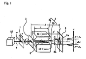
- the distance D (Refer to Fig. 1 ) from a screen to the observation plane can be supposed to be about 3.5cm (Refer to Non-patent Reference 3, Fig. 1 ).
- a silver atomic beam 6 emitted by the particle source 50 begins to split into two beams 6a and 6b around the region encircled by a circle 5 written by a broken line and completely split at the exit of an electromagnet 3.
- Non-patent Reference 5 the following idea was introduced: Let the two waves split up and down once by the electromagnet superpose again by making them pass through another pair of magnetic poles etc. without any intermediate observation on the glass plate. Then, by observing whether or not interference occurs, it will be seen whether or not the reduction of a wave packet occurs at first on the glass plate. However, as seen from Fig. 1 , since any silver atom with a + spin can never be found out in the wave that has split and curved upward, interference will never occur even if the split waves could be superposed again. In other words for confirmation, for a single silver atom to occur interference, a probability wave itself representing the silver atom must be split into two.
- each individual silver atom having up spin and each individual atom having down spin could be separately taken out.
- the reason why a silver atomic spin is identical with an electronic spin is considered that the silver atomic spin is caused by a 5s electron in the outermost shell of the silver atom.
- the pattern of evaporated silver atoms having down spins and the pattern of evaporated silver atoms having up spins are symmetric with respect to the z axis and are connected with each other at both ends of each of these patterns overlapped on the yaxis in the observation plane (plane surface of the glass plate) .
- Fig. 2A is a schematic diagram of a spin isolation apparatus 100 of this invention for isolating individual particles having spins whose every sign is either one of the two different signs. Taking the case of silver atoms as particles having spins will provide explanations in this embodiment.
- the position of an outline 4' traced by dotted lines in Fig. 2A corresponds to the position where the glass plate 4 was placed in Fig. 1 .
- the mask (screen) 8 is placed just before the plate 7 placed at the position of the outline 4'.
- This mask has a rectangular aperture 9.
- the breadth of the exterior outline of the evaporation pattern was 1.1 mm in the case of the Stern-Gerlach experimental apparatus (Refer to Non-patent Reference 1, Fig. 5).
- the width of the aperture 9 in the direction along the y axis should, for example, be determined as 0.5 mm.
- the thin film 10 of silver having - spin and the thin film 11 of silver having + spin are separately obtained spatially on the plate (receiving section) 7 over which the mask (trajectory restricting section) 8 is newly provided.
- the evaporation pattern 12 including thin film parts of silver evaporated in a mixture of silver atoms having - spins and silver atoms having + spins is remained on the mask 8.
- the aperture 9 can be divided into two apertures by providing a narrow screen parallel to the y axis as the need arises.
- a slit of the width w and length s is located on each of the two screens 1 and 2 that constitute a slit-collimator. Making the length s of the slit short for making the width of the evaporated pattern on the plate shorter than the width of the aperture 9 on the mask 8 also results this separation of the evaporated pattern.
- particles to which the spin isolation apparatus can be applied are not restricted to silver atoms.
- particle source 50 silver atomic source
- neutrons can be divided into neutrons having - spins and neutrons having + spins.
- isolation of each individual particle in response to every specific sign of its spin becomes-possible.
Landscapes
- Physics & Mathematics (AREA)
- Spectroscopy & Molecular Physics (AREA)
- Engineering & Computer Science (AREA)
- General Engineering & Computer Science (AREA)
- High Energy & Nuclear Physics (AREA)
- Analysing Materials By The Use Of Radiation (AREA)
- Particle Accelerators (AREA)
- Hall/Mr Elements (AREA)
Claims (3)
- Spin-Isolationseinrichtung, die Teilchen, die jeweils einen Spin haben, auf der Grundlage eines Vorzeichens des Spins jedes Teilchens isoliert, welche Vorrichtung folgendes aufweist:eine Teilchenquelle (50), die die Teilchen entlang einer x-Achse emittiert;einen Empfangsteil (7), der die von der Teilchenquelle emittierten Teilchen empfängt;einen Stern-Gerlach Elektromagneten (3), der zwei durch einen vorbestimmten Spalt voneinander getrennt angeordnete Magnetpole aufweist und der zwischen der Teilchenquelle und dem Empfangsteil angeordnet ist und die Teilchen entlang einer z-Achse in erste Teilchen, die jeweils einen Spin mit einem positiven Vorzeichen haben, und zweite Teilchen separiert, die jeweils einen Spin mit einem negativen Vorzeichen haben, gekennzeichnet durcheinen Trajektorien-Beschränkungsteil unmittelbar vor dem Empfangsteil, der dazu konfiguriert ist, die Trajektorien der ersten Teilchen und/oder der zweiten Teilchen in y-Richtung zu beschränken, um die ersten und zweiten Teilchen, die von dem Empfangsteil zu empfangen sind, räumlich zu isolieren.
- Spin-Isolationseinrichtung nach Anspruch 1, bei der der Trajektorien-Beschränkungsteil ein Schirm ist, der eine Öffnung mit seiner vorbestimmten Breite in y-Richtung hat und in der Nähe des Empfangsteils zwischen dem Elektromagneten und dem Empfangsteil angeordnet ist.
- Spin-Isolatioinseinrichtung nach Anspruch 1, bei der die Teilchen, die jeweils den Spin haben, Neutronen sind, der Trajektorien-Beschränkungsteil dazu konfiguriert ist, die Trajektorien der Neutronen in y-Richtung zu beschränken, um zumindest erste Neutronen, die jeweils den Spin mit den positiven Vorzeichen haben und zweite Neutronen, die jeweils den Spin mit dem negativen Vorzeichen haben, zu liefern,
und der Empfangsteil durch ein Neutronen absorbierenden Material gebildet wird.
Applications Claiming Priority (2)
| Application Number | Priority Date | Filing Date | Title |
|---|---|---|---|
| PCT/JP2005/024266 WO2007077617A2 (ja) | 2005-12-28 | 2005-12-28 | 二元力学に基づき設計された装置及びその設計方法 |
| PCT/JP2006/326127 WO2007077890A1 (ja) | 2005-12-28 | 2006-12-27 | スピン分離装置、スピン非対称物質の製造方法、電流源及び信号処理方法 |
Related Child Applications (1)
| Application Number | Title | Priority Date | Filing Date |
|---|---|---|---|
| EP13187751 Division-Into | 2013-10-08 |
Publications (3)
| Publication Number | Publication Date |
|---|---|
| EP1973118A1 EP1973118A1 (de) | 2008-09-24 |
| EP1973118A4 EP1973118A4 (de) | 2011-03-30 |
| EP1973118B1 true EP1973118B1 (de) | 2014-07-02 |
Family
ID=40091396
Family Applications (1)
| Application Number | Title | Priority Date | Filing Date |
|---|---|---|---|
| EP06843509.8A Expired - Fee Related EP1973118B1 (de) | 2005-12-28 | 2006-12-27 | Spin-isolationseinrichtung, |
Country Status (3)
| Country | Link |
|---|---|
| US (2) | US8101920B2 (de) |
| EP (1) | EP1973118B1 (de) |
| WO (1) | WO2007077890A1 (de) |
Families Citing this family (7)
| Publication number | Priority date | Publication date | Assignee | Title |
|---|---|---|---|---|
| EP1973118B1 (de) * | 2005-12-28 | 2014-07-02 | Takashi Suzuki | Spin-isolationseinrichtung, |
| EP2385542B1 (de) * | 2010-05-07 | 2013-01-02 | ICT Integrated Circuit Testing Gesellschaft für Halbleiterprüftechnik mbH | Elektronenstrahlvorrichtung mit Dispersionskompensation und Betriebsverfahren dafür |
| US20140266159A1 (en) * | 2013-03-15 | 2014-09-18 | Ohio State Innovation Foundation | High temperature hall sensor for magnetic position sensing |
| WO2017009817A1 (en) * | 2015-08-11 | 2017-01-19 | Majlesi Hosein | Electron intrinsic spin analyzer |
| US11402445B2 (en) | 2015-10-27 | 2022-08-02 | Hosein Majlesi | Electron intrinsic spin analyzer |
| CA3124481C (en) | 2019-01-24 | 2022-01-25 | Quantum Valley Investment Fund LP | Collimator system |
| US12566380B2 (en) * | 2024-05-27 | 2026-03-03 | Eric Arno Vigen | Lithography using spin isolated monochromatic electromagnetic radiation |
Family Cites Families (9)
| Publication number | Priority date | Publication date | Assignee | Title |
|---|---|---|---|---|
| US3113207A (en) * | 1960-03-01 | 1963-12-03 | Bell Telephone Labor Inc | Particle separation apparatus utilizing congruent inhomogeneous magnetostatic and electrostatic fields |
| US3461294A (en) * | 1965-12-30 | 1969-08-12 | Atomic Energy Commission | Method for generating a beam of ions wherein the ions are completely polarized |
| JPS6014432A (ja) | 1983-07-05 | 1985-01-25 | Sharp Corp | アモルフアス半導体製造法 |
| JP3400670B2 (ja) * | 1997-03-03 | 2003-04-28 | 理化学研究所 | 中性子ビームの制御方法及び制御装置 |
| JPH11340835A (ja) * | 1998-05-28 | 1999-12-10 | Sony Corp | 信号処理装置およびその信号処理方法 |
| JP2001313236A (ja) * | 2000-04-27 | 2001-11-09 | Yoshiaki Takahashi | 電気二重層コンデンサー |
| JP3537086B2 (ja) | 2000-09-08 | 2004-06-14 | 独立行政法人産業技術総合研究所 | スピンエレクトロニクス材料およびその作製方法 |
| JP4528941B2 (ja) | 2003-12-05 | 2010-08-25 | 学校法人慶應義塾 | 一次元多層有機金属錯体ナノ磁気素子及び一次元多層有機金属錯体 |
| EP1973118B1 (de) * | 2005-12-28 | 2014-07-02 | Takashi Suzuki | Spin-isolationseinrichtung, |
-
2006
- 2006-12-27 EP EP06843509.8A patent/EP1973118B1/de not_active Expired - Fee Related
- 2006-12-27 WO PCT/JP2006/326127 patent/WO2007077890A1/ja not_active Ceased
- 2006-12-27 US US12/087,152 patent/US8101920B2/en not_active Expired - Fee Related
-
2011
- 2011-12-15 US US13/326,389 patent/US20120091361A1/en not_active Abandoned
Non-Patent Citations (1)
| Title |
|---|
| P. SCHIEMENZ ET AL: "Permanent sextupole magnets for polarized Stern-Gerlach-type atomic beam sources", REVIEW OF SCIENTIFIC INSTRUMENTS, vol. 63, no. 4, 1 January 1992 (1992-01-01), pages 2634, XP055019002, ISSN: 0034-6748, DOI: 10.1063/1.1142862 * |
Also Published As
| Publication number | Publication date |
|---|---|
| WO2007077890A1 (ja) | 2007-07-12 |
| US20090107895A1 (en) | 2009-04-30 |
| US20120091361A1 (en) | 2012-04-19 |
| US8101920B2 (en) | 2012-01-24 |
| EP1973118A4 (de) | 2011-03-30 |
| EP1973118A1 (de) | 2008-09-24 |
Similar Documents
| Publication | Publication Date | Title |
|---|---|---|
| Edelstein | Spin polarization of conduction electrons induced by electric current in two-dimensional asymmetric electron systems | |
| US20120091361A1 (en) | Spin isolation apparatus, spin asymmetric material producing method, current source, and signal processing method | |
| Nara et al. | Equation of state dependence of directed flow in a microscopic transport model | |
| Nikolić et al. | Transverse spin-orbit force in the spin Hall effect in ballistic semiconductor wires | |
| Hashimoto et al. | Gauge angle dependence in time-dependent Hartree-Fock-Bogoliubov calculations of O 20+ O 20 head-on collisions with the Gogny interaction | |
| Brandão et al. | Evolution of zero-field ferrimagnetic domains and skyrmions in exchange-coupled Pt/CoGd/Pt confined nanostructures: Implications for antiferromagnetic devices | |
| Tanaka et al. | Effects on magnetic reconnection of a density asymmetry across the current sheet | |
| Zhang et al. | Symmetry-breaking assisted Landau-Zener transitions in Rydberg atoms | |
| Burgdörfer | Dynamic screening and wake effects on electronic excitation in ion-solid and ion-surface collisions | |
| Mukhopadhyay et al. | Resonance structures in kink-antikink scattering in a quantum vacuum | |
| Maggs et al. | Magnetic fluctuations associated with field‐aligned striations | |
| Benjamin et al. | Entangled electronic states in multiple-quantum-dot systems | |
| Mozer et al. | Magnetic field reconnection: a first-principles perspective | |
| Volovik | $\hbar $ as parameter of Minkowski metric in effective theory | |
| Fujikawa | Theory of intrinsic and extrinsic excitation effects in deep core XPS spectra studied by the many-body scattering theory | |
| Omidi et al. | Hybrid simulation of the curved dayside magnetopause during southward IMF | |
| Van Otterlo et al. | Quantum vortex dynamics in Josephson junction arrays | |
| JP5122978B2 (ja) | スピン分離装置 | |
| JP5319802B2 (ja) | スピン分離装置、スピン非対称物質の製造方法、電流源及び信号処理方法 | |
| Hasenbusch | Analysis of inclusive semileptonic B meson decays with τ lepton final states at the Belle experiment | |
| Martin Jr et al. | The energetic ion signature of an O-type neutral line in the geomagnetic tail | |
| Biermann | The origin of highest energy cosmic rays and cosmic magnetic fields | |
| US20060267583A1 (en) | Methods and devices for medium manipulation using quantum spin | |
| Jovanović et al. | On the stability of shear‐Alfvén vortices | |
| Frankfurt et al. | Angular-momentum constraints in the light-cone quantum mechanics of the nucleon-nucleon system |
Legal Events
| Date | Code | Title | Description |
|---|---|---|---|
| PUAI | Public reference made under article 153(3) epc to a published international application that has entered the european phase |
Free format text: ORIGINAL CODE: 0009012 |
|
| 17P | Request for examination filed |
Effective date: 20080725 |
|
| AK | Designated contracting states |
Kind code of ref document: A1 Designated state(s): DE GB |
|
| DAX | Request for extension of the european patent (deleted) | ||
| RBV | Designated contracting states (corrected) |
Designated state(s): DE GB |
|
| A4 | Supplementary search report drawn up and despatched |
Effective date: 20110302 |
|
| 17Q | First examination report despatched |
Effective date: 20120215 |
|
| REG | Reference to a national code |
Ref country code: DE Ref legal event code: R079 Ref document number: 602006042170 Country of ref document: DE Free format text: PREVIOUS MAIN CLASS: G21K0001000000 Ipc: G21K0001160000 |
|
| GRAP | Despatch of communication of intention to grant a patent |
Free format text: ORIGINAL CODE: EPIDOSNIGR1 |
|
| RIC1 | Information provided on ipc code assigned before grant |
Ipc: G21K 1/16 20060101AFI20130513BHEP |
|
| INTG | Intention to grant announced |
Effective date: 20130603 |
|
| GRAP | Despatch of communication of intention to grant a patent |
Free format text: ORIGINAL CODE: EPIDOSNIGR1 |
|
| INTG | Intention to grant announced |
Effective date: 20131108 |
|
| GRAP | Despatch of communication of intention to grant a patent |
Free format text: ORIGINAL CODE: EPIDOSNIGR1 |
|
| INTG | Intention to grant announced |
Effective date: 20140124 |
|
| GRAS | Grant fee paid |
Free format text: ORIGINAL CODE: EPIDOSNIGR3 |
|
| GRAA | (expected) grant |
Free format text: ORIGINAL CODE: 0009210 |
|
| AK | Designated contracting states |
Kind code of ref document: B1 Designated state(s): DE GB |
|
| REG | Reference to a national code |
Ref country code: GB Ref legal event code: FG4D |
|
| REG | Reference to a national code |
Ref country code: DE Ref legal event code: R096 Ref document number: 602006042170 Country of ref document: DE Effective date: 20140814 |
|
| REG | Reference to a national code |
Ref country code: DE Ref legal event code: R097 Ref document number: 602006042170 Country of ref document: DE |
|
| PLBE | No opposition filed within time limit |
Free format text: ORIGINAL CODE: 0009261 |
|
| STAA | Information on the status of an ep patent application or granted ep patent |
Free format text: STATUS: NO OPPOSITION FILED WITHIN TIME LIMIT |
|
| 26N | No opposition filed |
Effective date: 20150407 |
|
| PGFP | Annual fee paid to national office [announced via postgrant information from national office to epo] |
Ref country code: GB Payment date: 20191223 Year of fee payment: 14 Ref country code: DE Payment date: 20191227 Year of fee payment: 14 |
|
| REG | Reference to a national code |
Ref country code: DE Ref legal event code: R119 Ref document number: 602006042170 Country of ref document: DE |
|
| GBPC | Gb: european patent ceased through non-payment of renewal fee |
Effective date: 20201227 |
|
| PG25 | Lapsed in a contracting state [announced via postgrant information from national office to epo] |
Ref country code: DE Free format text: LAPSE BECAUSE OF NON-PAYMENT OF DUE FEES Effective date: 20210701 Ref country code: GB Free format text: LAPSE BECAUSE OF NON-PAYMENT OF DUE FEES Effective date: 20201227 |