EP1972792B1 - Tauchpumpenanordnung - Google Patents
Tauchpumpenanordnung Download PDFInfo
- Publication number
- EP1972792B1 EP1972792B1 EP08004746.7A EP08004746A EP1972792B1 EP 1972792 B1 EP1972792 B1 EP 1972792B1 EP 08004746 A EP08004746 A EP 08004746A EP 1972792 B1 EP1972792 B1 EP 1972792B1
- Authority
- EP
- European Patent Office
- Prior art keywords
- electrode
- sensor body
- sensor
- pump
- ske
- Prior art date
- Legal status (The legal status is an assumption and is not a legal conclusion. Google has not performed a legal analysis and makes no representation as to the accuracy of the status listed.)
- Not-in-force
Links
- XLYOFNOQVPJJNP-UHFFFAOYSA-N water Substances O XLYOFNOQVPJJNP-UHFFFAOYSA-N 0.000 claims description 28
- 101000825598 Homo sapiens Spindle and kinetochore-associated protein 2 Proteins 0.000 claims description 5
- 102100022924 Spindle and kinetochore-associated protein 2 Human genes 0.000 claims description 5
- 238000005259 measurement Methods 0.000 claims description 2
- 238000011156 evaluation Methods 0.000 description 5
- 238000001514 detection method Methods 0.000 description 4
- 239000012530 fluid Substances 0.000 description 3
- 238000011161 development Methods 0.000 description 2
- 230000018109 developmental process Effects 0.000 description 2
- 238000005086 pumping Methods 0.000 description 2
- 230000003247 decreasing effect Effects 0.000 description 1
- 230000001419 dependent effect Effects 0.000 description 1
- 238000009434 installation Methods 0.000 description 1
- 125000006850 spacer group Chemical group 0.000 description 1
Images

Classifications
-
- F—MECHANICAL ENGINEERING; LIGHTING; HEATING; WEAPONS; BLASTING
- F04—POSITIVE - DISPLACEMENT MACHINES FOR LIQUIDS; PUMPS FOR LIQUIDS OR ELASTIC FLUIDS
- F04D—NON-POSITIVE-DISPLACEMENT PUMPS
- F04D13/00—Pumping installations or systems
- F04D13/02—Units comprising pumps and their driving means
- F04D13/06—Units comprising pumps and their driving means the pump being electrically driven
- F04D13/08—Units comprising pumps and their driving means the pump being electrically driven for submerged use
- F04D13/086—Units comprising pumps and their driving means the pump being electrically driven for submerged use the pump and drive motor are both submerged
-
- F—MECHANICAL ENGINEERING; LIGHTING; HEATING; WEAPONS; BLASTING
- F04—POSITIVE - DISPLACEMENT MACHINES FOR LIQUIDS; PUMPS FOR LIQUIDS OR ELASTIC FLUIDS
- F04D—NON-POSITIVE-DISPLACEMENT PUMPS
- F04D15/00—Control, e.g. regulation, of pumps, pumping installations or systems
- F04D15/02—Stopping of pumps, or operating valves, on occurrence of unwanted conditions
- F04D15/0209—Stopping of pumps, or operating valves, on occurrence of unwanted conditions responsive to a condition of the working fluid
- F04D15/0218—Stopping of pumps, or operating valves, on occurrence of unwanted conditions responsive to a condition of the working fluid the condition being a liquid level or a lack of liquid supply
-
- G—PHYSICS
- G01—MEASURING; TESTING
- G01F—MEASURING VOLUME, VOLUME FLOW, MASS FLOW OR LIQUID LEVEL; METERING BY VOLUME
- G01F23/00—Indicating or measuring liquid level or level of fluent solid material, e.g. indicating in terms of volume or indicating by means of an alarm
- G01F23/22—Indicating or measuring liquid level or level of fluent solid material, e.g. indicating in terms of volume or indicating by means of an alarm by measuring physical variables, other than linear dimensions, pressure or weight, dependent on the level to be measured, e.g. by difference of heat transfer of steam or water
- G01F23/24—Indicating or measuring liquid level or level of fluent solid material, e.g. indicating in terms of volume or indicating by means of an alarm by measuring physical variables, other than linear dimensions, pressure or weight, dependent on the level to be measured, e.g. by difference of heat transfer of steam or water by measuring variations of resistance of resistors due to contact with conductor fluid
- G01F23/241—Indicating or measuring liquid level or level of fluent solid material, e.g. indicating in terms of volume or indicating by means of an alarm by measuring physical variables, other than linear dimensions, pressure or weight, dependent on the level to be measured, e.g. by difference of heat transfer of steam or water by measuring variations of resistance of resistors due to contact with conductor fluid for discrete levels
-
- H—ELECTRICITY
- H01—ELECTRIC ELEMENTS
- H01H—ELECTRIC SWITCHES; RELAYS; SELECTORS; EMERGENCY PROTECTIVE DEVICES
- H01H35/00—Switches operated by change of a physical condition
- H01H35/18—Switches operated by change of liquid level or of liquid density, e.g. float switch
Definitions
- the invention relates to a submersible pump assembly with a sensor arrangement according to the preamble of claim 1.
- Such an arrangement is for example of any of JP-A-2006070729 or JP-A-2006274819 known.
- Submersible pumps are often provided with an automatic switch arrangement, by means of which the motor of the submersible pump installed on a base is turned on when the water level above the base reaches an upper level and the pump is automatically designed when the water level drops below a lower level.
- switch arrangements for example, float switches are used.
- a sensor body can be held in relative to the base and the pump housing height adjustable position on the housing. So describes the Japanese patent application JP-A-2006070729 a submersible pump, to which a guide rod extending vertically in the normal operating position of the pump is mounted, on which two capacitive sensors which are displaceable relative to their height position are located one above the other. Each of these two sensors is connected to the pump control via an electrical line.
- the invention is described in claim 1.
- the dependent claims contain advantageous refinements and developments of the invention.
- the invention Based on a submersible pump assembly with a sensor arrangement with a relative to a pump housing (and thus relative to the base) height adjustable sensor body which has at least a first, the presence of water at the location of the sensor body electrode, the invention provides according to claim 1, among others in that the sensor arrangement contains at least one further electrode and in that the first electrode of the sensor body is height-adjustable relative to the further electrode.
- the at least one further electrode results in advantageous functional configurations of the submersible pump arrangement with extremely little effort.
- the further electrode is arranged with respect to the pump housing fixed position and below the first electrode.
- the first electrode By height adjustment downwards, the first electrode can be brought into direct contact with the further electrode via its adjustment region and causes continuous operation of the pump in this direct contact.
- this results in a particularly simple and advantageous way to proceed from the operation of the pump with automatic on and off to a setting with continuous operation, as in direct contact of the two electrodes regardless of the presence of water there is always a low resistance between the first and the further electrode and, without changing the evaluation of the sensor signal of the sensor arrangement, the pump continues to run independently of the water level, in particular even if the water level continues to fall.
- a further electrode may be provided on a further sensor body, which in turn is height-adjustable relative to the pump housing and relative to the first sensor body.
- the two sensor bodies can advantageously be used for upper and lower switching points of a switching hysteresis corresponding to the behavior of the conventional float switch.
- the interconnection of Sensor signals from the two sensor bodies can be made in different ways.
- the two sensor bodies can be arranged vertically one above the other in a line, resulting in an inevitable order in the relative altitude of the two sensor body.
- the two sensor body can also be laterally separated from each other and positioned in different relative vertical position to each other, so that both the first sensor body can be higher than the second sensor body and also the second sensor body can be higher than the first sensor body.
- Fig. 1 shows a submersible pump TP with a pump housing PG, which is erected on legs SB on a base.
- the intake of the pump is hidden in the drawing provided on the underside of the pump facing the base.
- suction openings can also be arranged on the lateral lower edge of the pump housing.
- the legs SB can be made much shorter or completely eliminated and replaced by other spacers between the intake of the submersible pump and the base.
- the arranged in the pump housing PG electric motor of the submersible pump assembly can be supplied via a power cable NK with electrical power.
- a first sensor body SKE is guided in a height-adjustable manner, which can be positioned steplessly or in discrete different height positions relative to the pump housing.
- the sensor body SKE is connected via a cable KAE with an electric or electronic control device arranged in the pump housing.
- the cable KAE can also be designed in particular in the form of a so-called spiral cable.
- a first electrode EE is formed, which points in the sketched preferred example of the sensor body SKE on its underside down.
- the shape of the electrode EE is subordinate to the function of the submersible pump arrangement.
- the detection of the water level around the pump takes place by means of the first sensor body SKE in such a way that the electrical resistance between the first electrode EE and a lower reference electrode EM, which is arranged fixedly on the pump housing, is measured.
- the electrical resistance between the first electrode EE and the reference electrode EM is very high.
- the resistance between the first electrode EE and the reference electrode EM abruptly drops to a much lower value, so that the electrical resistance or the reciprocal of the electrical conductivity between the first electrode EE and the reference electrode EM can be detected the presence of water at the location of the first electrode EE or the first sensor body SKE carrying this.
- the first sensor body SKE also have two electrodes which can come into contact with the surrounding water, again measuring the resistance between two such electrodes on the sensor body SKE and deriving therefrom a statement about the presence of water at the level of the sensor body SKE becomes.
- the pump is turned on when the sensor assembly detects the occurrence of water at the level of the first sensor body SKE.
- the detection of the presence of water at the location of the first sensor body SKE can also be carried out by measuring a different physical quantity, for example a capacity or a thermal conductivity of the environment.
- An automatic shutdown can be carried out by the control device when no more water is detected at the location of the first sensor body SKE via the first electrode EE.
- the rate of pumping out of water by the pump on the one hand and the rate of inflow of water is approximately equal can lead to frequent switching on and off of the pump can be provided in a conventional manner to introduce a switching hysteresis between two water levels, as is also the case with the conventional float switches.
- Such a switching hysteresis can for example be given by the fact that a lower water level, below which the pump is turned off, is detected by a further electrode disposed in a fixed position on the pump housing.
- the further electrode can be provided, for example, by the electrode EM or by another further electrode arranged in a relatively low position in a stationary manner on the housing.
- a further electrode is provided on a further sensor body SKA, which is largely hidden in the view of the figure and indicated only with SKA.
- the further sensor body may advantageously be formed substantially equal to the first sensor body SKE.
- the further sensor body SKA can also use the electrode EM as a reference electrode common to the sensor body SKE for the measurement of an electrical variable, in particular an electrical resistance or an electrical conductance.
- the further sensor body SKA is preferably vertically displaceable in the same way as the first sensor body SKE in a recess AA of the housing and a guide groove provided there and can be positioned in different height positions. Independently of the sensor body SKE, the sensor body SKA supplies its own sensor signal to an evaluation or control device of the submersible pump arrangement.
- one of the two sensor bodies for example the first sensor body SKE in a higher position for detecting an upper water level and the other sensor body SKA in a lower position for the detection of a lower water level is set and the sensor signal of the first sensor body to turn on and the sensor signal of the second Sensor body used to turn off the pump in the control and evaluation.
- first sensor body SKE and the further sensor body SKA are height-adjustable in separate guides
- it can also be provided to guide the two sensor bodies one above the other in the same recess and guide. Which determines the vertical sequence of the two sensor bodies.
- the first sensor body SKE or, if several sensor bodies are present at least one of the sensor bodies can be brought into a position in which the sensor signal of this sensor body in the control and evaluation device is a continuous operation of the pump independently of the current one Water level, so even at a further decreasing level causes.
- a separate switch can be saved for this purpose.
- the electrode EE of the first sensor body SKE can be contacted directly by displacing the first sensor body SKE downwards with the reference electrode EM, whereby the resistance between the first electrode EE and the reference electrode EM regardless of the water level is low and is evaluated in the control and evaluation without fundamental change in Ausensekriterien as if water was present at the position of the first sensor body, which may be specified as Einschaltkriterium in a preferred embodiment.
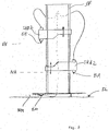
- Fig. 2 shows a sensor arrangement with two height-adjustable sensor bodies, which are guided vertically adjustable in a common guide SF.
- the electrode EE projecting downwards from the first sensor body SKE2 and secured thereto can be attached to the electrode EE Sensor body SKA2 is guided in a sliding movement past downwards, until the sensor body SKE2 abuts in the vertical direction on the sensor body SKA2 and therefore can not be moved further down.
- very small height differences between the electrode EE and the electrode EA can be adjusted.
- the height of the first electrode EE above the footprint SL is denoted by NE, the height of the electrode EA above the footprint with NA.
- a further electrode EM is arranged at a small height distance NM from the base and can, as in the example according to Fig. 1 , in cooperation with the first electrode EE in direct contact of these two electrodes serve to cause a continuous operation of the pump.
- the electrode EA is without function.
Landscapes
- Engineering & Computer Science (AREA)
- Physics & Mathematics (AREA)
- Mechanical Engineering (AREA)
- General Engineering & Computer Science (AREA)
- Thermal Sciences (AREA)
- Fluid Mechanics (AREA)
- General Physics & Mathematics (AREA)
- Control Of Non-Positive-Displacement Pumps (AREA)
- Structures Of Non-Positive Displacement Pumps (AREA)
Description
- Die Erfindung betrifft eine Tauchpumpenanordnung mit einer Sensoranordnung nach dem Oberbegriff des Anspruchs 1. Eine solche Anordnung ist z.B. aus irgendeiner der
JP-A-2006070729 JP-A-2006274819 - Tauchpumpen sind häufig mit einer automatischen Schalteranordnung versehen, mittels welcher der Motor der auf einer Grundfläche aufgestellten Tauchpumpe eingeschaltet wird, wenn der Wasserstand über der Grundfläche einen oberen Pegel erreicht und die Pumpe automatisch ausgestaltet wird, wenn der Wasserstand unter einen unteren Pegel absinkt. Für solche Schalteranordnungen sind beispielsweise Schwimmerschalter eingesetzt. In anderer Ausführung kann ein Sensorkörper in relativ zur Grundfläche und zum Pumpengehäuse höhenverstellbarer Position an dem Gehäuse gehalten sein.
So beschreibt die japanische OffenlegungsschriftJP-A-2006070729 JP-A-2006274819
Auch die DruckschriftWO 96/19621 A1
Der Erfindung liegt die Aufgabe zugrunde, eine vorteilhafte Tauchpumpenanordnung mit einer Sensoranordnung mit einem relativ zu einem Pumpengehäuse höhenverstellbaren Sensorkörper anzugeben. - Die Erfindung ist im Anspruch 1 beschrieben. Die abhängigen Ansprüche enthalten vorteilhafte Ausgestaltungen und Weiterbildungen der Erfindung.
Ausgehend von einer Tauchpumpenanordnung mit einer Sensoranordnung mit einem relativ zu einem Pumpengehäuse (und damit auch relativ zur Grundfläche) höhenverstellbaren Sensorkörper, welcher wenigstens eine erste, die Anwesenheit von Wasser am Ort des Sensorkörpers detektierende Elektrode besitzt, sieht die Erfindung gemäß Anspruch 1 unter anderem vor, dass die Sensoranordnung wenigstens eine weitere Elektrode enthält und dass die erste Elektrode des Sensorkörpers relativ zu der weiteren Elektrode höhenverstellbar ist.
Durch die wenigstens eine weitere Elektrode ergeben sich vorteilhafte funktionale Ausgestaltungen der Tauchpumpenanordnung mit äußerst geringem Aufwand.
Die weitere Elektrode an bezüglich des Pumpengehäuses fester Position und unterhalb der ersten Elektrode angeordnet. Die erste Elektrode ist durch Höhenverstellung nach unten über ihren Verstellbereich mit der weiteren Elektrode in direkten Kontakt bringbar und bewirkt in diesem direkten Kontakt einen Dauerbetrieb der Pumpe. Insbesondere bei einer bevorzugten Detektion von Wasser am Ort des höhenverstellbaren Sensorkörpers ergibt sich hierdurch eine besonders einfache und vorteilhafte Möglichkeit, von dem Betrieb der Pumpe mit automatischer Ein- und Ausschaltung zu einer Einstellung mit Dauerbetrieb überzugehen, da bei direktem Kontakt der beiden Elektroden unabhängig vom Vorhandensein von Wasser immer ein geringer Widerstand zwischen der ersten und der weiteren Elektrode besteht und ohne Änderung der Auswertung des Sensorsignals der Sensoranordnung die Pumpe unabhängig vom Wasserstand, insbesondere also auch bei weiter absinkendem Wasserstand weiterläuft.
In anderer vorteilhafter Ausführungsform kann eine weitere Elektrode an einem weiteren Sensorkörper vorgesehen sein, welcher seinerseits relativ zum Pumpengehäuse und relativ zu dem ersten Sensorkörper höhenverstellbar ist. Die beiden Sensorkörper können vorteilhafterweise für obere und untere Schaltpunkte einer Schalthysterese entsprechend dem Verhalten der gebräuchlichen Schwimmerschalter dienen. Die Verschaltung der Sensorsignale von den beiden Sensorkörpern kann auf unterschiedliche Weise erfolgen. Die beiden Sensorkörper können vertikal übereinander in einer Linie angeordnet sein, wodurch sich eine zwangsläufige Reihenfolge in der relativen Höhenlage der beiden Sensorkörper ergibt. In anderer Ausführung können die beiden Sensorkörper auch seitlich voneinander getrennt und in unterschiedlicher relativer Vertikalposition zueinander positioniert werden, so dass sowohl der erste Sensorkörper höher als der zweite Sensorkörper liegen kann und auch der zweite Sensorkörper höher liegen kann als der erste Sensorkörper. - Die Erfindung ist nachfolgend anhand eines bevorzugten Ausführungsbeispiels unter Bezugnahme auf die Abbildung noch eingehend veranschaulicht. Dabei zeigt
- Fig. 1
- eine Schrägansicht einer Pumpe mit einer Sensoranordnung.
- Fig. 2
- eine Sensoranordnung mit zwei höhenverstellbaren Sensorkörpern.
-
Fig. 1 zeigt eine Tauchpumpe TP mit einem Pumpengehäuse PG, welches über Standbeine SB auf einer Grundfläche aufstellbar ist. Die Ansaugöffnung der Pumpe sei in der Zeichnung verdeckt an der Unterseite der Pumpe der Grundfläche zugewandt vorgesehen. Ansaugöffnungen können aber auch am seitlichen unteren Rand des Pumpengehäuses angeordnet sein. Für die Aufstellung der Pumpe auf einer Grundfläche sind verschiedene Anordnungen und verschiedene Distanzen der Ansaugöffnung über der Grundfläche an sich bekannt. Insbesondere für flachsaugende Tauchpumpen können die Standbeine SB wesentlich kürzer ausgeführt sein oder auch ganz entfallen und durch andere Abstandselemente zwischen der Ansaugöffnung der Tauchpumpe und der Grundfläche ersetzt sein. - Der in dem Pumpengehäuse PG angeordnete Elektromotor der Tauchpumpenanordnung ist über ein Netzkabel NK mit elektrischer Leistung versorgbar.
- In einer ersten Aussparung AE ist eine in normaler Betriebsposition der Pumpe vertikal verlaufende Führung FKA, beispielsweise in Form einer Nut, ausgebildet. In der Aussparung AE und der Nut FKA ist ein erster Sensorkörper SKE höhenverstellbar geführt, welcher stufenlos oder in diskreten verschiedenen Höhenpositionen relativ zum Pumpengehäuse positionierbar ist. Der Sensorkörper SKE ist über ein Kabel KAE mit einer im Pumpengehäuse angeordneten elektrischen oder elektronischen Steuereinrichtung verbunden. Das Kabel KAE kann insbesondere auch in Form eines sog. Spiralkabels ausgeführt sein.
- An dem Sensorkörper SKE ist eine erste Elektrode EE ausgebildet, welche im skizzierten bevorzugten Beispiel von dem Sensorkörper SKE an dessen Unterseite nach unten weist. Die Form der Elektrode EE ist für die Funktion der Tauchpumpenanordnung nachrangig. Die Detektion des Wasserpegels um die Pumpe erfolgt mittels des ersten Sensorkörpers SKE in der Weise, dass der elektrische Widerstand zwischen der ersten Elektrode EE und einer tiefer angeordneten Bezugselektrode EM, welche ortsfest an dem Pumpengehäuse angeordnet ist, gemessen wird. Solange die erste Elektrode EE des ersten Sensorkörper SKE nicht mit die Pumpe umgebenden Wasser in Kontakt ist, ist der elektrische Widerstand zwischen der ersten Elektrode EE und der Bezugselektrode EM sehr hoch. Wenn bei steigendem Wasserpegel die Wasseroberfläche die erste Elektrode EE erreicht, sinkt der Widerstand zwischen der ersten Elektrode EE und der Bezugselektrode EM schlagartig auf einen wesentlich niedrigeren Wert, so dass aus dem elektrischen Widerstand oder aus der reziproken Größe der elektrischen Leitfähigkeit zwischen der ersten Elektrode EE und der Bezugselektrode EM die Anwesenheit von Wasser am Ort der ersten Elektrode EE bzw. des diese tragenden ersten Sensorkörpers SKE festgestellt werden kann.
In anderer Ausführung kann auch der erste Sensorkörper SKE zwei Elektroden besitzen, welche mit dem umgebenden Wasser in Kontakt treten können, wobei wiederum der Widerstand zwischen zwei solchen Elektroden am Sensorkörper SKE gemessen und daraus eine Aussage über das Vorliegen von Wasser auf Höhe des Sensorkörpers SKE abgeleitet wird.
Typischerweise wird die Pumpe eingeschaltet, wenn die Sensoranordnung das Auftreten von Wasser auf Höhe des ersten Sensorkörpers SKE festgestellt wird.
Die Detektion der Anwesenheit von Wasser am Ort des ersten Sensorkörpers SKE kann auch durch Messung einer andern physikalischen Größe, beispielsweise einer Kapazität oder einer Wärmeleitfähigkeit der Umgebung vorgenommen werden.
Eine automatische Abschaltung kann durch die Steuereinrichtung dann erfolgen, wenn am Ort des ersten Sensorkörpers SKE über die erste Elektrode EE kein Wasser mehr detektiert wird. Da dies in Fällen, bei welchen die Rate des Abpumpens von Wasser durch die Pumpe einerseits und die Rate des Zuflusses von Wasser annähernd gleich groß sind, zu einem häufigen Ein- und Ausschalten der Pumpe führen kann, kann in an sich bekannter Weise vorgesehen sein, eine Schalthysterese zwischen zwei Pegelständen einzuführen, wie dies bei den gebräuchlichen Schwimmerschaltern auch gegeben ist. Eine solche Schalthysterese kann beispielsweise dadurch gegeben sein, dass ein unterer Wasserpegel, bei dessen Unterschreiten die Pumpe ausgeschaltet wird, durch eine in fester Position am Pumpengehäuse angeordnete weitere Elektrode detektiert wird. Die weitere Elektrode kann beispielsweise je nach Ausführung des Messprinzips durch die Elektrode EM oder durch eine weitere, in relativ tiefer Position ortsfest am Gehäuse angeordnete weitere Elektrode gegeben sein. - In bevorzugter Ausführungsform ist eine weitere Elektrode an einem weiteren Sensorkörper SKA vorgesehen, welcher in der Ansicht der Abbildung weitgehend verdeckt und nur mit SKA bezeichnet angedeutet ist. Der weitere Sensorkörper kann vorteilhafterweise im wesentlichen gleich zu dem ersten Sensorkörper SKE ausgebildet sein. Insbesondere kann der weitere Sensorkörper SKA auch die Elektrode EM als mit dem Sensorkörper SKE gemeinsame Bezugselektrode für die Messung einer elektrischen Größe, insbesondere eines elektrischen Widerstands bzw. eines elektrischen Leitwerts benutzen.
- Der weitere Sensorkörper SKA ist vorzugsweise in gleicher Art wie der erste Sensorkörper SKE in einer Aussparung AA des Gehäuses und einer dort vorgesehenen Führungsnut vertikal verschiebbar und in verschiedenen Höhenpositionen positionierbar. Der Sensorkörper SKA liefert unabhängig von dem Sensorkörper SKE ein eigenes Sensorsignal an eine Auswerte- oder Steuereinrichtung der Tauchpumpenanordnung.
- Typischerweise wird einer der beiden Sensorkörper, beispielsweise der erste Sensorkörper SKE in einer höheren Position zur Detektion eines oberen Wasserpegels und der andere Sensorkörper SKA in einer tieferen Position für die Detektion eines unteren Wasserpegels eingestellt und das Sensorsignal des ersten Sensorkörper zum Einschalten und das Sensorsignal des zweiten Sensorkörpers zum Ausschalten der Pumpe in der Steuer- und Auswerteeinrichtung herangezogen.
- Während in der in der Abbildung skizzierten Ausführungsform der erste Sensorkörper SKE und der weitere Sensorkörper SKA in getrennten Führungen höhenverstellbar sind, kann in anderer Ausführung auch vorgesehen sein, die beiden Sensorkörper übereinander in derselben Aussparung und Führung zu führen. Wodurch die vertikale Aufeinanderfolge der beiden Sensorkörper festgelegt ist.
- In einer besonders vorteilhaften Weiterbildung kann vorgesehen sein, dass der erste Sensorkörper SKE oder, bei Vorliegen mehrerer Sensorkörper wenigstens einer der Sensorkörper in eine Position gebracht werden kann, in welcher das Sensorsignal dieses Sensorkörpers in der Steuer- und Auswerteeinrichtung einen Dauerbetrieb der Pumpe unabhängig vom aktuellen Wasserpegel, also auch bei weiter absinkendem Pegel, bewirkt. Durch die Verwendung wenigstens eines Sensorkörpers für eine solche Dauerbetriebsfunktion kann ein separater Schalter hierfür eingespart werden.
- Im skizzierten Beispiel ist für eine solche Dauerbetriebsfunktion in vorteilhafter Ausführung vorgesehen, dass die Elektrode EE des ersten Sensorkörpers SKE durch Verschieben des ersten Sensorkörpers SKE nach unten mit der Bezugselektrode EM direkt kontaktiert werden kann, wodurch der Widerstand zwischen der ersten Elektrode EE und der Bezugselektrode EM unabhängig vom Wasserstand niedrig ist und in der Steuer- und Auswerteeinrichtung ohne grundlegende Änderung der Auswertekriterien so bewertet wird, als wäre Wasser an der Position des ersten Sensorkörpers vorhanden, was als Einschaltkriterium in bevorzugter Ausführung vorgegeben sein kann.
-
Fig. 2 zeigt eine Sensoranordnung mit zwei höhenverstellbaren Sensorkörpern, welche in einer gemeinsamen Führung SF höhenverstellbar geführt sind. Durch die Führung beider Sensorkörper SKE2 und SKA2 in derselben Führung SF ist immer gewährleistet, dass der erste Sensorkörper SKE2, welcher die für die Einschaltung der Pumpe dienende Sensorelektrode EE trägt, immer bezüglich der Standfläche FL der Pumpe höher liegt als der zweite Sensorkörper SKA2, welcher eine Elektrode EA trägt, deren Funktion auch bereits zu der Anordnung nachFig. 1 erläutert ist. Vorteilhafterweise kann die von dem ersten Sensorkörper SKE2 nach unten ragende und an diesem befestigte Elektrode EE an dem Sensorkörper SKA2 in einer Verschiebebewegung nach unten vorbei geführt werden, bis der Sensorkörper SKE2 in vertikaler Richtung an dem Sensorkörper SKA2 anliegt und deshalb nicht weiter nach unten verschoben werden kann. Hierdurch können auch sehr geringe Höhenunterschiede zwischen der Elektrode EE und der Elektrode EA eingestellt werden. Die Höhe der ersten Elektrode EE über der Standfläche SL ist mit NE bezeichnet, die Höhe der Elektrode EA über der Standfläche mit NA. Eine weitere Elektrode EM ist in geringem Höhenabstand NM von der Standfläche angeordnet und kann, wie in dem Beispiel nachFig. 1 , in Zusammenwirken mit der ersten Elektrode EE bei direktem Kontakt dieser beiden Elektroden dazu dienen, einen Dauerbetrieb der Pumpe zu bewirken. Die Elektrode EA ist dabei ohne Funktion.
Claims (3)
- Tauchpumpenanordnung mit einer Sensoranordnung mit einem relativ zu einem Pumpengehäuse (TP) höhenverstellbaren Sensorkörper (SKE) mit wenigstens einer ersten, die Anwesenheit von Wasser am Ort des Sensorkörpers (SKE, SKE2) detektierenden Elektrode (EE) und einer Steuereinrichtung zur Auswertung eines von der Sensoranordnung gewonnenen Sensorsignals zum Ein- und/oder Ausschalten der Pumpe (TP),
wobei die Sensoranordnung wenigstens eine weitere Elektrode (EM) enthält und die erste Elektrode (EE) relativ zu der weiteren Elektrode höhenverstellbar ist dadurch gekennzeichnet,
dass die weitere Elektrode (EM) an bezüglich des Pumpengehäuses (PG) fester Position angeordnet ist,
dass die weitere Elektrode (EM) unterhalb der ersten Elektrode (EE) angeordnet ist,
und dass die erste Elektrode (EE) durch Höhenverstellung nach unten in direktem Kontakt mit der weiteren Elektrode (EM) bringbar ist. - Anordnung nach Anspruch 1, dadurch gekennzeichnet, dass eine weitere Elektrode an einem weiteren Sensorkörper (SKA, SKA2) angeordnet ist, welche relativ zu dem ersten Sensorkörper (SKE, SKE2) und relativ zum Pumpengehäuse (PG) höhenverstellbar ist.
- Anordnung nach einem der Ansprüche 1 bis 2, dadurch gekennzeichnet, dass die Sensoranordnung die Anwesenheit von Wasser über die Messung der elektrischen Leitfähigkeit bzw. des elektrischen Widerstands zwischen zwei Elektroden (EE, EM, EA) detektiert.
Applications Claiming Priority (1)
| Application Number | Priority Date | Filing Date | Title |
|---|---|---|---|
| DE102007012855A DE102007012855A1 (de) | 2007-03-17 | 2007-03-17 | Tauchpumpenanordnung |
Publications (3)
| Publication Number | Publication Date |
|---|---|
| EP1972792A2 EP1972792A2 (de) | 2008-09-24 |
| EP1972792A3 EP1972792A3 (de) | 2010-03-31 |
| EP1972792B1 true EP1972792B1 (de) | 2018-05-02 |
Family
ID=39575636
Family Applications (1)
| Application Number | Title | Priority Date | Filing Date |
|---|---|---|---|
| EP08004746.7A Not-in-force EP1972792B1 (de) | 2007-03-17 | 2008-03-14 | Tauchpumpenanordnung |
Country Status (2)
| Country | Link |
|---|---|
| EP (1) | EP1972792B1 (de) |
| DE (1) | DE102007012855A1 (de) |
Families Citing this family (6)
| Publication number | Priority date | Publication date | Assignee | Title |
|---|---|---|---|---|
| CN101852213A (zh) * | 2009-03-30 | 2010-10-06 | 黄文笔 | 内置电容式水位控制器的潜水泵 |
| DE102011120547B4 (de) | 2011-12-02 | 2018-10-18 | Technische Universität Dresden | Brennhilfsmittel, als Träger für Bauteile bei einer Wärmebehandlung |
| DE102011120837B4 (de) | 2011-12-13 | 2014-10-16 | AL-KO Geräte GmbH | Tauchpumpe für Flüssigkeit mit automatischer Schaltvorrichtung |
| ITMI20130025A1 (it) * | 2013-01-10 | 2014-07-11 | Liliana Combi | Pompa sommergibile perfezionata con campo di funzionamento regolabile |
| MX389080B (es) * | 2013-03-19 | 2025-03-20 | Flow Control LLC | Bomba de bajo perfil con la capacidad de ser montada en varias configuraciones. |
| CN115788919A (zh) | 2021-09-09 | 2023-03-14 | 创科无线普通合伙 | 潜水泵 |
Family Cites Families (5)
| Publication number | Priority date | Publication date | Assignee | Title |
|---|---|---|---|---|
| US4437811A (en) * | 1980-06-30 | 1984-03-20 | Ebara Corporation | Submersible pump with alternate pump operation control means |
| US5553794A (en) * | 1994-12-22 | 1996-09-10 | Tarby Inc | Sewage handling system |
| JP4417483B2 (ja) * | 1999-07-28 | 2010-02-17 | 株式会社鶴見製作所 | 水中電動ポンプの自動運転用脱着式液位検出具 |
| JP2006070729A (ja) | 2004-08-31 | 2006-03-16 | Shin Meiwa Ind Co Ltd | 水中ポンプ |
| JP2006274819A (ja) | 2005-03-28 | 2006-10-12 | Shin Meiwa Ind Co Ltd | 水中ポンプ |
-
2007
- 2007-03-17 DE DE102007012855A patent/DE102007012855A1/de not_active Withdrawn
-
2008
- 2008-03-14 EP EP08004746.7A patent/EP1972792B1/de not_active Not-in-force
Also Published As
| Publication number | Publication date |
|---|---|
| EP1972792A2 (de) | 2008-09-24 |
| EP1972792A3 (de) | 2010-03-31 |
| DE102007012855A1 (de) | 2008-09-18 |
Similar Documents
| Publication | Publication Date | Title |
|---|---|---|
| EP1701646B1 (de) | Geschirrspülmaschine mit einem system zur füllstandserkennung | |
| EP1972792A2 (de) | Tauchpumpenanordnung | |
| DE602005000519T2 (de) | Sitzsensor mit Schalter auf Folie und Widerstandselement | |
| DE3843243A1 (de) | Vorrichtung zur feststellung des alkoholgehaltes und/oder des heizwertes von kraftstoffen | |
| DE102011002009A1 (de) | Kapazitiver Weggeber | |
| DE4324268C2 (de) | Vorrichtung zum Erfassen zweier Pegel einer elektrisch leitenden Flüssigkeit | |
| EP3091234B1 (de) | Tauchpumpe | |
| DE3024123C2 (de) | Überwachungsgerät für eine Ansaugpumpe | |
| DE212008000062U1 (de) | Linearantrieb | |
| EP2256469B1 (de) | Vorrichtung zum Anzeigen und/oder Kontrollieren von Fluiden | |
| EP4127632A1 (de) | Vorrichtung zur temperaturmessung und vorrichtung zur stromermittlung | |
| WO2004070321A1 (de) | Sensoranordnung | |
| DE2900413C3 (de) | Flüssigkeitsstandanzeiger, insbesondere für Treibstoffbehälter von Kraftfahrzeugen | |
| DE2000047A1 (de) | Elektrische Druckmessdose zur stufenweisen Umsetzung eines zu ueberwachenden Gas- oder Fluessigkeitsdruckes in elektrische Widerstandswerte | |
| DE29508802U1 (de) | Tauch- oder Schlürfpumpe | |
| DE102015103386B4 (de) | Touch-Control-Regelwiderstand | |
| DE3515767A1 (de) | Vorrichtung zur ermittlung und ueberwachung der beschaffenheit, des zustands und des fuellstands einer druckfluessigkeit | |
| DE202018103191U1 (de) | Hupenmodul für ein Fahrzeuglenkrad und Baugruppe mit einem Fahrer-Airbagmodul und einem Hupenmodul | |
| WO2003081175A1 (de) | Neigungssensor | |
| DE19717422C2 (de) | Durchflußwächter | |
| DE19823190B4 (de) | Füllstandssensor mit Schwimmer | |
| DE102004035284B4 (de) | Positionssensoranordnung mit mehreren in einer Reihe angeordneten, magnetfeldsensitiven Sensoren, insbesondere Hall-Sensoren | |
| DE4104903A1 (de) | Vorrichtung zur feststellung des kraftstoff-fuellstands in einem kraftfahrzeug-tank | |
| AT526790B1 (de) | Stromversorgungsvorrichtung zur Stromversorgung eines Ausziehelements | |
| DE3909647A1 (de) | Messfuehlervorrichtung fuer den kraftstoffstand in einem fahrzeugtank |
Legal Events
| Date | Code | Title | Description |
|---|---|---|---|
| PUAI | Public reference made under article 153(3) epc to a published international application that has entered the european phase |
Free format text: ORIGINAL CODE: 0009012 |
|
| AK | Designated contracting states |
Kind code of ref document: A2 Designated state(s): AT BE BG CH CY CZ DE DK EE ES FI FR GB GR HR HU IE IS IT LI LT LU LV MC MT NL NO PL PT RO SE SI SK TR |
|
| AX | Request for extension of the european patent |
Extension state: AL BA MK RS |
|
| PUAL | Search report despatched |
Free format text: ORIGINAL CODE: 0009013 |
|
| AK | Designated contracting states |
Kind code of ref document: A3 Designated state(s): AT BE BG CH CY CZ DE DK EE ES FI FR GB GR HR HU IE IS IT LI LT LU LV MC MT NL NO PL PT RO SE SI SK TR |
|
| AX | Request for extension of the european patent |
Extension state: AL BA MK RS |
|
| 17P | Request for examination filed |
Effective date: 20100824 |
|
| AKX | Designation fees paid |
Designated state(s): AT BE BG CH CY CZ DE DK EE ES FI FR GB GR HR HU IE IS IT LI LT LU LV MC MT NL NO PL PT RO SE SI SK TR |
|
| RAP1 | Party data changed (applicant data changed or rights of an application transferred) |
Owner name: HUSQVARNA AB |
|
| 17Q | First examination report despatched |
Effective date: 20160915 |
|
| STAA | Information on the status of an ep patent application or granted ep patent |
Free format text: STATUS: EXAMINATION IS IN PROGRESS |
|
| GRAP | Despatch of communication of intention to grant a patent |
Free format text: ORIGINAL CODE: EPIDOSNIGR1 |
|
| STAA | Information on the status of an ep patent application or granted ep patent |
Free format text: STATUS: GRANT OF PATENT IS INTENDED |
|
| INTG | Intention to grant announced |
Effective date: 20171211 |
|
| GRAS | Grant fee paid |
Free format text: ORIGINAL CODE: EPIDOSNIGR3 |
|
| GRAA | (expected) grant |
Free format text: ORIGINAL CODE: 0009210 |
|
| STAA | Information on the status of an ep patent application or granted ep patent |
Free format text: STATUS: THE PATENT HAS BEEN GRANTED |
|
| AK | Designated contracting states |
Kind code of ref document: B1 Designated state(s): AT BE BG CH CY CZ DE DK EE ES FI FR GB GR HR HU IE IS IT LI LT LU LV MC MT NL NO PL PT RO SE SI SK TR |
|
| REG | Reference to a national code |
Ref country code: GB Ref legal event code: FG4D Free format text: NOT ENGLISH |
|
| REG | Reference to a national code |
Ref country code: CH Ref legal event code: EP Ref country code: AT Ref legal event code: REF Ref document number: 995562 Country of ref document: AT Kind code of ref document: T Effective date: 20180515 |
|
| REG | Reference to a national code |
Ref country code: DE Ref legal event code: R096 Ref document number: 502008016052 Country of ref document: DE Ref country code: IE Ref legal event code: FG4D Free format text: LANGUAGE OF EP DOCUMENT: GERMAN |
|
| REG | Reference to a national code |
Ref country code: NL Ref legal event code: MP Effective date: 20180502 |
|
| REG | Reference to a national code |
Ref country code: LT Ref legal event code: MG4D |
|
| PG25 | Lapsed in a contracting state [announced via postgrant information from national office to epo] |
Ref country code: NO Free format text: LAPSE BECAUSE OF FAILURE TO SUBMIT A TRANSLATION OF THE DESCRIPTION OR TO PAY THE FEE WITHIN THE PRESCRIBED TIME-LIMIT Effective date: 20180802 Ref country code: ES Free format text: LAPSE BECAUSE OF FAILURE TO SUBMIT A TRANSLATION OF THE DESCRIPTION OR TO PAY THE FEE WITHIN THE PRESCRIBED TIME-LIMIT Effective date: 20180502 Ref country code: LT Free format text: LAPSE BECAUSE OF FAILURE TO SUBMIT A TRANSLATION OF THE DESCRIPTION OR TO PAY THE FEE WITHIN THE PRESCRIBED TIME-LIMIT Effective date: 20180502 Ref country code: SE Free format text: LAPSE BECAUSE OF FAILURE TO SUBMIT A TRANSLATION OF THE DESCRIPTION OR TO PAY THE FEE WITHIN THE PRESCRIBED TIME-LIMIT Effective date: 20180502 Ref country code: FI Free format text: LAPSE BECAUSE OF FAILURE TO SUBMIT A TRANSLATION OF THE DESCRIPTION OR TO PAY THE FEE WITHIN THE PRESCRIBED TIME-LIMIT Effective date: 20180502 Ref country code: BG Free format text: LAPSE BECAUSE OF FAILURE TO SUBMIT A TRANSLATION OF THE DESCRIPTION OR TO PAY THE FEE WITHIN THE PRESCRIBED TIME-LIMIT Effective date: 20180802 |
|
| PG25 | Lapsed in a contracting state [announced via postgrant information from national office to epo] |
Ref country code: HR Free format text: LAPSE BECAUSE OF FAILURE TO SUBMIT A TRANSLATION OF THE DESCRIPTION OR TO PAY THE FEE WITHIN THE PRESCRIBED TIME-LIMIT Effective date: 20180502 Ref country code: LV Free format text: LAPSE BECAUSE OF FAILURE TO SUBMIT A TRANSLATION OF THE DESCRIPTION OR TO PAY THE FEE WITHIN THE PRESCRIBED TIME-LIMIT Effective date: 20180502 Ref country code: NL Free format text: LAPSE BECAUSE OF FAILURE TO SUBMIT A TRANSLATION OF THE DESCRIPTION OR TO PAY THE FEE WITHIN THE PRESCRIBED TIME-LIMIT Effective date: 20180502 Ref country code: GR Free format text: LAPSE BECAUSE OF FAILURE TO SUBMIT A TRANSLATION OF THE DESCRIPTION OR TO PAY THE FEE WITHIN THE PRESCRIBED TIME-LIMIT Effective date: 20180803 |
|
| PG25 | Lapsed in a contracting state [announced via postgrant information from national office to epo] |
Ref country code: PT Free format text: LAPSE BECAUSE OF FAILURE TO SUBMIT A TRANSLATION OF THE DESCRIPTION OR TO PAY THE FEE WITHIN THE PRESCRIBED TIME-LIMIT Effective date: 20180903 |
|
| PG25 | Lapsed in a contracting state [announced via postgrant information from national office to epo] |
Ref country code: EE Free format text: LAPSE BECAUSE OF FAILURE TO SUBMIT A TRANSLATION OF THE DESCRIPTION OR TO PAY THE FEE WITHIN THE PRESCRIBED TIME-LIMIT Effective date: 20180502 Ref country code: PL Free format text: LAPSE BECAUSE OF FAILURE TO SUBMIT A TRANSLATION OF THE DESCRIPTION OR TO PAY THE FEE WITHIN THE PRESCRIBED TIME-LIMIT Effective date: 20180502 Ref country code: DK Free format text: LAPSE BECAUSE OF FAILURE TO SUBMIT A TRANSLATION OF THE DESCRIPTION OR TO PAY THE FEE WITHIN THE PRESCRIBED TIME-LIMIT Effective date: 20180502 Ref country code: SK Free format text: LAPSE BECAUSE OF FAILURE TO SUBMIT A TRANSLATION OF THE DESCRIPTION OR TO PAY THE FEE WITHIN THE PRESCRIBED TIME-LIMIT Effective date: 20180502 Ref country code: CZ Free format text: LAPSE BECAUSE OF FAILURE TO SUBMIT A TRANSLATION OF THE DESCRIPTION OR TO PAY THE FEE WITHIN THE PRESCRIBED TIME-LIMIT Effective date: 20180502 Ref country code: RO Free format text: LAPSE BECAUSE OF FAILURE TO SUBMIT A TRANSLATION OF THE DESCRIPTION OR TO PAY THE FEE WITHIN THE PRESCRIBED TIME-LIMIT Effective date: 20180502 |
|
| REG | Reference to a national code |
Ref country code: DE Ref legal event code: R097 Ref document number: 502008016052 Country of ref document: DE |
|
| PLBE | No opposition filed within time limit |
Free format text: ORIGINAL CODE: 0009261 |
|
| STAA | Information on the status of an ep patent application or granted ep patent |
Free format text: STATUS: NO OPPOSITION FILED WITHIN TIME LIMIT |
|
| 26N | No opposition filed |
Effective date: 20190205 |
|
| PG25 | Lapsed in a contracting state [announced via postgrant information from national office to epo] |
Ref country code: SI Free format text: LAPSE BECAUSE OF FAILURE TO SUBMIT A TRANSLATION OF THE DESCRIPTION OR TO PAY THE FEE WITHIN THE PRESCRIBED TIME-LIMIT Effective date: 20180502 |
|
| PG25 | Lapsed in a contracting state [announced via postgrant information from national office to epo] |
Ref country code: MC Free format text: LAPSE BECAUSE OF FAILURE TO SUBMIT A TRANSLATION OF THE DESCRIPTION OR TO PAY THE FEE WITHIN THE PRESCRIBED TIME-LIMIT Effective date: 20180502 |
|
| REG | Reference to a national code |
Ref country code: CH Ref legal event code: PL |
|
| GBPC | Gb: european patent ceased through non-payment of renewal fee |
Effective date: 20190314 |
|
| PG25 | Lapsed in a contracting state [announced via postgrant information from national office to epo] |
Ref country code: LU Free format text: LAPSE BECAUSE OF NON-PAYMENT OF DUE FEES Effective date: 20190314 |
|
| REG | Reference to a national code |
Ref country code: BE Ref legal event code: MM Effective date: 20190331 |
|
| PG25 | Lapsed in a contracting state [announced via postgrant information from national office to epo] |
Ref country code: LI Free format text: LAPSE BECAUSE OF NON-PAYMENT OF DUE FEES Effective date: 20190331 Ref country code: GB Free format text: LAPSE BECAUSE OF NON-PAYMENT OF DUE FEES Effective date: 20190314 Ref country code: IE Free format text: LAPSE BECAUSE OF NON-PAYMENT OF DUE FEES Effective date: 20190314 Ref country code: CH Free format text: LAPSE BECAUSE OF NON-PAYMENT OF DUE FEES Effective date: 20190331 |
|
| PG25 | Lapsed in a contracting state [announced via postgrant information from national office to epo] |
Ref country code: FR Free format text: LAPSE BECAUSE OF NON-PAYMENT OF DUE FEES Effective date: 20190331 Ref country code: BE Free format text: LAPSE BECAUSE OF NON-PAYMENT OF DUE FEES Effective date: 20190331 |
|
| PG25 | Lapsed in a contracting state [announced via postgrant information from national office to epo] |
Ref country code: TR Free format text: LAPSE BECAUSE OF FAILURE TO SUBMIT A TRANSLATION OF THE DESCRIPTION OR TO PAY THE FEE WITHIN THE PRESCRIBED TIME-LIMIT Effective date: 20180502 |
|
| PG25 | Lapsed in a contracting state [announced via postgrant information from national office to epo] |
Ref country code: MT Free format text: LAPSE BECAUSE OF FAILURE TO SUBMIT A TRANSLATION OF THE DESCRIPTION OR TO PAY THE FEE WITHIN THE PRESCRIBED TIME-LIMIT Effective date: 20180502 |
|
| REG | Reference to a national code |
Ref country code: AT Ref legal event code: MM01 Ref document number: 995562 Country of ref document: AT Kind code of ref document: T Effective date: 20190314 |
|
| PG25 | Lapsed in a contracting state [announced via postgrant information from national office to epo] |
Ref country code: AT Free format text: LAPSE BECAUSE OF NON-PAYMENT OF DUE FEES Effective date: 20190314 |
|
| PG25 | Lapsed in a contracting state [announced via postgrant information from national office to epo] |
Ref country code: CY Free format text: LAPSE BECAUSE OF FAILURE TO SUBMIT A TRANSLATION OF THE DESCRIPTION OR TO PAY THE FEE WITHIN THE PRESCRIBED TIME-LIMIT Effective date: 20180502 |
|
| PG25 | Lapsed in a contracting state [announced via postgrant information from national office to epo] |
Ref country code: IS Free format text: LAPSE BECAUSE OF FAILURE TO SUBMIT A TRANSLATION OF THE DESCRIPTION OR TO PAY THE FEE WITHIN THE PRESCRIBED TIME-LIMIT Effective date: 20180902 |
|
| PG25 | Lapsed in a contracting state [announced via postgrant information from national office to epo] |
Ref country code: HU Free format text: LAPSE BECAUSE OF FAILURE TO SUBMIT A TRANSLATION OF THE DESCRIPTION OR TO PAY THE FEE WITHIN THE PRESCRIBED TIME-LIMIT; INVALID AB INITIO Effective date: 20080314 |
|
| PGFP | Annual fee paid to national office [announced via postgrant information from national office to epo] |
Ref country code: IT Payment date: 20230116 Year of fee payment: 16 Ref country code: DE Payment date: 20230206 Year of fee payment: 16 |
|
| P01 | Opt-out of the competence of the unified patent court (upc) registered |
Effective date: 20230419 |
|
| REG | Reference to a national code |
Ref country code: DE Ref legal event code: R119 Ref document number: 502008016052 Country of ref document: DE |
|
| PG25 | Lapsed in a contracting state [announced via postgrant information from national office to epo] |
Ref country code: DE Free format text: LAPSE BECAUSE OF NON-PAYMENT OF DUE FEES Effective date: 20241001 |
|
| PG25 | Lapsed in a contracting state [announced via postgrant information from national office to epo] |
Ref country code: DE Free format text: LAPSE BECAUSE OF NON-PAYMENT OF DUE FEES Effective date: 20241001 |
|
| PG25 | Lapsed in a contracting state [announced via postgrant information from national office to epo] |
Ref country code: IT Free format text: LAPSE BECAUSE OF NON-PAYMENT OF DUE FEES Effective date: 20240314 |