EP1972490A1 - Second-row seat for a motor vehicle having a backrest and sitting surface that can both be tipped over - Google Patents
Second-row seat for a motor vehicle having a backrest and sitting surface that can both be tipped over Download PDFInfo
- Publication number
- EP1972490A1 EP1972490A1 EP07425164A EP07425164A EP1972490A1 EP 1972490 A1 EP1972490 A1 EP 1972490A1 EP 07425164 A EP07425164 A EP 07425164A EP 07425164 A EP07425164 A EP 07425164A EP 1972490 A1 EP1972490 A1 EP 1972490A1
- Authority
- EP
- European Patent Office
- Prior art keywords
- designed
- seat according
- sitting surface
- backrest
- hinge
- Prior art date
- Legal status (The legal status is an assumption and is not a legal conclusion. Google has not performed a legal analysis and makes no representation as to the accuracy of the status listed.)
- Granted
Links
Images

Classifications
-
- B—PERFORMING OPERATIONS; TRANSPORTING
- B60—VEHICLES IN GENERAL
- B60N—SEATS SPECIALLY ADAPTED FOR VEHICLES; VEHICLE PASSENGER ACCOMMODATION NOT OTHERWISE PROVIDED FOR
- B60N2/00—Seats specially adapted for vehicles; Arrangement or mounting of seats in vehicles
- B60N2/24—Seats specially adapted for vehicles; Arrangement or mounting of seats in vehicles for particular purposes or particular vehicles
- B60N2/30—Non-dismountable or dismountable seats storable in a non-use position, e.g. foldable spare seats
- B60N2/3002—Non-dismountable or dismountable seats storable in a non-use position, e.g. foldable spare seats back-rest movements
- B60N2/3004—Non-dismountable or dismountable seats storable in a non-use position, e.g. foldable spare seats back-rest movements by rotation only
- B60N2/3009—Non-dismountable or dismountable seats storable in a non-use position, e.g. foldable spare seats back-rest movements by rotation only about transversal axis
- B60N2/3013—Non-dismountable or dismountable seats storable in a non-use position, e.g. foldable spare seats back-rest movements by rotation only about transversal axis the back-rest being hinged on the vehicle frame
-
- B—PERFORMING OPERATIONS; TRANSPORTING
- B60—VEHICLES IN GENERAL
- B60N—SEATS SPECIALLY ADAPTED FOR VEHICLES; VEHICLE PASSENGER ACCOMMODATION NOT OTHERWISE PROVIDED FOR
- B60N2/00—Seats specially adapted for vehicles; Arrangement or mounting of seats in vehicles
- B60N2/24—Seats specially adapted for vehicles; Arrangement or mounting of seats in vehicles for particular purposes or particular vehicles
- B60N2/30—Non-dismountable or dismountable seats storable in a non-use position, e.g. foldable spare seats
- B60N2/3038—Cushion movements
- B60N2/304—Cushion movements by rotation only
- B60N2/3045—Cushion movements by rotation only about transversal axis
- B60N2/305—Cushion movements by rotation only about transversal axis the cushion being hinged on the vehicle frame
-
- B—PERFORMING OPERATIONS; TRANSPORTING
- B60—VEHICLES IN GENERAL
- B60N—SEATS SPECIALLY ADAPTED FOR VEHICLES; VEHICLE PASSENGER ACCOMMODATION NOT OTHERWISE PROVIDED FOR
- B60N2/00—Seats specially adapted for vehicles; Arrangement or mounting of seats in vehicles
- B60N2/24—Seats specially adapted for vehicles; Arrangement or mounting of seats in vehicles for particular purposes or particular vehicles
- B60N2/32—Seats specially adapted for vehicles; Arrangement or mounting of seats in vehicles for particular purposes or particular vehicles convertible for other use
- B60N2/36—Seats specially adapted for vehicles; Arrangement or mounting of seats in vehicles for particular purposes or particular vehicles convertible for other use into a loading platform
-
- B—PERFORMING OPERATIONS; TRANSPORTING
- B60—VEHICLES IN GENERAL
- B60N—SEATS SPECIALLY ADAPTED FOR VEHICLES; VEHICLE PASSENGER ACCOMMODATION NOT OTHERWISE PROVIDED FOR
- B60N2/00—Seats specially adapted for vehicles; Arrangement or mounting of seats in vehicles
- B60N2/24—Seats specially adapted for vehicles; Arrangement or mounting of seats in vehicles for particular purposes or particular vehicles
- B60N2/42—Seats specially adapted for vehicles; Arrangement or mounting of seats in vehicles for particular purposes or particular vehicles the seat constructed to protect the occupant from the effect of abnormal g-forces, e.g. crash or safety seats
- B60N2/4249—Seats specially adapted for vehicles; Arrangement or mounting of seats in vehicles for particular purposes or particular vehicles the seat constructed to protect the occupant from the effect of abnormal g-forces, e.g. crash or safety seats fixed structures, i.e. where neither the seat nor a part thereof are displaced during a crash
- B60N2/4256—Seats specially adapted for vehicles; Arrangement or mounting of seats in vehicles for particular purposes or particular vehicles the seat constructed to protect the occupant from the effect of abnormal g-forces, e.g. crash or safety seats fixed structures, i.e. where neither the seat nor a part thereof are displaced during a crash the shape of the seat being specially adapted for a particular purpose or for particular vehicles
- B60N2/4263—Seats specially adapted for vehicles; Arrangement or mounting of seats in vehicles for particular purposes or particular vehicles the seat constructed to protect the occupant from the effect of abnormal g-forces, e.g. crash or safety seats fixed structures, i.e. where neither the seat nor a part thereof are displaced during a crash the shape of the seat being specially adapted for a particular purpose or for particular vehicles with anti-submarining systems
-
- B—PERFORMING OPERATIONS; TRANSPORTING
- B60—VEHICLES IN GENERAL
- B60N—SEATS SPECIALLY ADAPTED FOR VEHICLES; VEHICLE PASSENGER ACCOMMODATION NOT OTHERWISE PROVIDED FOR
- B60N2/00—Seats specially adapted for vehicles; Arrangement or mounting of seats in vehicles
- B60N2/80—Head-rests
- B60N2/891—Head-rests with the head-rest being comma-shaped in side view
-
- B—PERFORMING OPERATIONS; TRANSPORTING
- B60—VEHICLES IN GENERAL
- B60N—SEATS SPECIALLY ADAPTED FOR VEHICLES; VEHICLE PASSENGER ACCOMMODATION NOT OTHERWISE PROVIDED FOR
- B60N2205/00—General mechanical or structural details
- B60N2205/30—Seat or seat parts characterised by comprising plural parts or pieces
Definitions
- the present invention relates to a second-row seat for a motor vehicle, having a backrest and sitting surface that can both be tipped over.
- a second-row seat in which the sitting surface is connected at the front to a fixed base via a pair of levers, which are turned so as to lower the front part of the sitting surface itself before knocking the corresponding backrest down thereon.
- the rear part of the sitting surface is in turn connected to the backrest by means of a complicated mechanism that comprises a pair of plates connected to the base by means of an articulated quadrilateral. Also in this case the resting surface remains limited to just the rear wall of the backrest.
- the aim of the invention is to provide a second-row seat, which has a backrest and sitting surface that can both be tipped over and is designed to form an ample resting surface, which will also be convenient to operate and simple to produce.
- a second-row seat for a motor vehicle having a backrest and sitting surface that can be tipped over, as defined in Claim 1.
- a second-row seat of a motor vehicle in particular a car.
- the seat 1 comprises a sitting surface 2 and a backrest 3.
- sitting surface is meant the substantially horizontal part of the seat on which the user sits
- backrest is meant the part of the seat, normally in a sub-vertical position, on which the user rests his shoulders in use.
- the terms “front”, “rear”, “transverse” and “longitudinal” refer to the direction in which the motor vehicle is travelling.
- the term “hinge” indicates any articulated joint, irrespective of whether it is formed by a single segment or by a number of aligned segments.
- the second-row seat is in general also the rear seat.
- the second-row seat can be either a rear one or any intermediate seat between that of the driver and the rear seat.
- the second-row seat can be single for two or three passengers or else divided into two or three segments.
- a rear seat 1 is represented for just one passenger.
- the backrest 3 is pivoted, by means of a first fixed hinge 4, on two fixed supports 5 of the passenger compartment of the motor vehicle (not indicated in the drawings).
- the backrest 3 comprises a rigid frame, which is in itself known, a stuffed cushion 6 for resting of the user's back, and a rear surface, formed by a substantially plane rigid plate 7.
- the plate 7 constitutes a resting surface for the luggage that can be set as a continuation of the plane of the usual luggage compartment of the car.
- the plate 7 can be coated at the rear with a material suitable for loading and unloading luggage.
- the backrest 3 is finally provided with a headrest cushion 8, which can be height adjusted in any known way.
- the sitting surface 2 of the seat 1 has a front portion 9 ( Figure 1 ), fixed with respect to a rigid structure, which is preferably formed by two levers 11 fixed to the two sides of the portion 9 itself, on the corresponding rigid frame.
- the bottom end of each lever 11 is pivoted on a corresponding fixed hinge 12, which is set on a bracket 13 fixed on a fixed base or floor panel 14 of the car.
- the sitting surface 2 moreover comprises a rear portion 16 having a rigid frame of its own, separated from that of the front portion 9.
- the rigid frames of the two portions 9 and 16 of the sitting surface 2 are hinged together by means of a transverse mobile hinge 17.
- the sitting surface 2 is hence foldable on the hinge 17 so as to form a prolongation 18 ( Figure 4 ) of the resting surface formed by the plate 7.
- the fixed frame of the front portion 9 of the sitting surface 2 comprises a bottom surface 19 ( Figures 1 and 2 ) and a corresponding rear transverse surface 21, which are formed by a single shaped rigid plate, set on which is a corresponding stuffed cushion 23.
- the rigid frame of the rear portion 16 comprises a rear surface 24, a bottom surface 26, and a front transverse surface 27, which are formed by another shaped rigid plate, set on which is another stuffed cushion 29.
- the mobile hinge 17 is set in a position corresponding to the two bottom surfaces 19 and 26 of the two portions 9 and 16, in particular between a corner edge 31 of the bottom surface 19 with the corresponding transverse surface 21 and a corner edge 32 of the bottom surface 26 with the corresponding transverse surface 27.
- the two transverse surfaces 21 and 27 are plane and are designed to come into contact with one another in the distended position of the sitting surface 2, indicated in Figure 1 .
- the two transverse surfaces 21 and 27 are substantially perpendicular each to a portion of the corresponding bottom surface 19, 26 adjacent to the respective corner edge 31, 32.
- the prolongation 18 of the resting surface formed by the plate 7 is constituted by the two transverse surfaces 21 and 27 of the portions 9 and 16 when the sitting surface is in the folded position of Figure 4 . Consequently, the rear portion 16 is designed to rotate 9 on the mobile hinge 17 through 180° with respect to the front portion.
- the two transverse surfaces 21 and 27 can be coated with a material suitable for supporting the luggage, the same as or similar to that of the rear plate 7 of the backrest 3.
- the two levers 11 are designed to rotate on the hinge 12 through an angle ⁇ substantially of 90° until a front edge 28 of the stuffed cushion 23 comes to stop against a fixed arrest 30 of the passenger compartment of the motor vehicle.
- the length of the two levers 11 is sized according to the height of the backrest 3 and the width of the two transverse surfaces 21 and 27 of the portions 9 and 16 so that, in the folded position of Figure 4 , the prolongation 18 will set itself in a position adjacent to the resting surface formed by the plate 7.
- the rear portion 16 of the sitting surface 2 sets itself with a part of its bottom surface 26 in contact with a corresponding part of the bottom surface 19 of the front portion 9, whilst its stuffed cushion 29 sets itself in contact with the headrest cushion 8.
- At least one of said bottom surfaces 19 and 26 of the portions 9 and 16 of the sitting surface 2 is designed to stop against a fixed arrest carried by said base or floor panel 14 when said sitting surface 2 is in the distended position.
- the bottom surface 26 of the rear portion 16 comprises a plane area 33 designed to stop against a corresponding plane area 34 when the sitting surface 2 is in the distended position of Figure 1 .
- the two transverse surfaces 21 and 27 are also in contact with one another so that the plane area 34 also determines the longitudinal arrest of the sitting surface 2 backwards.
- the bottom surface 19 of the front portion 9 of the sitting surface presents a transverse depression 36 ( Figure 2 ), formed by a front shoulder 37 and by a rear shoulder 38, which is provided with a transverse notch 39.
- the floor panel 14 is provided with a transverse bar 41 having a border 42 projecting backwards and designed to engage the notch 39.
- the bottom wall of the depression 36 rests against the outer edge of the border 42, preventing forcing of the two transverse surfaces 21 and 27 under the weight of the passenger.
- the transverse bar 41 and the border 42 are housed in the depression 36, with the border 42 facing the notch 39.
- the sitting surface 2 tends to shift forwards and brings the notch 39 to engage the border 42, preventing both further displacement forwards of the sitting surface 2 and rotation of the portion 9 about the hinge 12 and of the rear portion 16 about the mobile hinge 17.
- the upright position of the backrest 3 ( Figure 1 ) is defined by the arrest, for example of the corresponding rear plate 7 against a fixed shoulder 43 of the passenger compartment of the motor vehicle, indicated only schematically in Figure 1 , on which the backrest 3 can be blocked by means of a lock, in itself known and not represented.
- the headrest cushion 8 is brought into the retracted position indicated in Figure 1 .
- the sitting surface 2 is rotated together with the levers 11 about the fixed hinge 12 in the counter-clockwise direction, and at the same time the rear portion 16 of the sitting surface 2 is rotated about the mobile hinge 17 in the clockwise direction, bringing the sitting surface 2 into the intermediate position indicated in Figure 3 .
- the advantages of the second-row seat according to the invention as compared to the seats of the known art are evident.
- the prolongation 18 of the resting surface formed by the rigid plate 7 increases considerably the space available for the luggage.
- the manoeuvre of tipping forwards and folding the sitting surface 2 is independent of that of tipping down the backrest 3.
- the bar 41 prevents any longitudinal displacement and tipping forwards of the sitting surface 2, preventing possible traumas for the passenger.
- the two levers 11 can be replaced by a continuous transverse structure.
- the two portions 9 and 16 of the sitting surface 2 can be equipped with manual grips for facilitating rotation of folding and distension of the sitting surface 2.
- the bottom surface 26 of the rear portion 16 can present a depression similar to the depression 36 of the bottom surface 19, which is designed to co-operate with a transverse bar of the floor panel 14 similar to the bar 41. In this case, the displacements forwards of the rear portion 16 of the sitting surface 2 in the event of sharp arrest of the motor vehicle are blocked independently of those of the front portion 9.
Landscapes
- Engineering & Computer Science (AREA)
- Aviation & Aerospace Engineering (AREA)
- Transportation (AREA)
- Mechanical Engineering (AREA)
- Seats For Vehicles (AREA)
Abstract
Description
- The present invention relates to a second-row seat for a motor vehicle, having a backrest and sitting surface that can both be tipped over.
- In motor vehicles having a second row of seats behind that of the driver, there is felt the need to be able to knock down the backrest of said seats in order to create a resting surface for the luggage, in general contiguous to that of the usual rear luggage compartment. Different types of seats are known with backrests that can be knocked down. In a known type, the sitting surface is fixed and the backrest is simply hinged with respect to the sitting surface. On account of the conformation of the sitting surface, this type of seat presents the drawback that folding of the backrest is limited and, given that the backrest remains inclined, it is not able to form an efficient resting surface for the luggage.
- Other types of seats have been proposed with backrests that can be knocked down in which also the sitting surface can be displaced so as to enable the backrest to set its rear wall in a substantially horizontal position. In one of these types of seats, the sitting surface can be tipped up forwards about a hinge adjacent to its front edge so as to set itself vertically against the front seat to enable the backrest to occupy the space of the sitting surface. This seat presents the drawback of limiting the resting surface for the luggage to just the rear wall of the backrest.
- There has also been proposed a second-row seat in which the sitting surface is connected at the front to a fixed base via a pair of levers, which are turned so as to lower the front part of the sitting surface itself before knocking the corresponding backrest down thereon. The rear part of the sitting surface is in turn connected to the backrest by means of a complicated mechanism that comprises a pair of plates connected to the base by means of an articulated quadrilateral. Also in this case the resting surface remains limited to just the rear wall of the backrest.
- The aim of the invention is to provide a second-row seat, which has a backrest and sitting surface that can both be tipped over and is designed to form an ample resting surface, which will also be convenient to operate and simple to produce.
- According to the invention, the above aim is achieved by a second-row seat for a motor vehicle having a backrest and sitting surface that can be tipped over, as defined in Claim 1.
- For a better understanding of the invention, described herein is a preferred embodiment, provided by way of example, with the aid of the annexed drawings, in which:
-
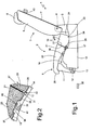
Figure 1 is a schematic lateral section of a second-row seat according to the invention, with backrest and sitting surface that can be tipped over; -
Figure 2 is a detail ofFigure 1 , at an enlarged scale; -
Figure 3 is the lateral section of the seat ofFigure 1 in an intermediate operating position; -
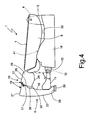
Figure 4 is the lateral section of the seat ofFigure 1 , with the sitting surface and the backrest tipped over. - With reference to
Figure 1 , designated as a whole by 1 is a second-row seat of a motor vehicle, in particular a car. The seat 1 comprises a sittingsurface 2 and abackrest 3. In the ensuing description, by the term "sitting surface" is meant the substantially horizontal part of the seat on which the user sits, whilst by the term "backrest" is meant the part of the seat, normally in a sub-vertical position, on which the user rests his shoulders in use. - Hereinafter the terms "front", "rear", "transverse" and "longitudinal" refer to the direction in which the motor vehicle is travelling. The term "hinge" indicates any articulated joint, irrespective of whether it is formed by a single segment or by a number of aligned segments. In cars, the second-row seat is in general also the rear seat. In other types of motor vehicles, the second-row seat can be either a rear one or any intermediate seat between that of the driver and the rear seat. In any case, the second-row seat can be single for two or three passengers or else divided into two or three segments. In the annexed drawings, a rear seat 1 is represented for just one passenger.
- The
backrest 3 is pivoted, by means of a firstfixed hinge 4, on twofixed supports 5 of the passenger compartment of the motor vehicle (not indicated in the drawings). Thebackrest 3 comprises a rigid frame, which is in itself known, a stuffedcushion 6 for resting of the user's back, and a rear surface, formed by a substantially planerigid plate 7. When thebackrest 3 is knocked down as inFigure 4 , theplate 7 constitutes a resting surface for the luggage that can be set as a continuation of the plane of the usual luggage compartment of the car. Advantageously, theplate 7 can be coated at the rear with a material suitable for loading and unloading luggage. Thebackrest 3 is finally provided with aheadrest cushion 8, which can be height adjusted in any known way. - The sitting
surface 2 of the seat 1 has a front portion 9 (Figure 1 ), fixed with respect to a rigid structure, which is preferably formed by twolevers 11 fixed to the two sides of theportion 9 itself, on the corresponding rigid frame. The bottom end of eachlever 11 is pivoted on a correspondingfixed hinge 12, which is set on abracket 13 fixed on a fixed base orfloor panel 14 of the car. - According to the invention, the sitting
surface 2 moreover comprises arear portion 16 having a rigid frame of its own, separated from that of thefront portion 9. The rigid frames of the twoportions surface 2 are hinged together by means of a transversemobile hinge 17. The sittingsurface 2 is hence foldable on thehinge 17 so as to form a prolongation 18 (Figure 4 ) of the resting surface formed by theplate 7. - In particular, the fixed frame of the
front portion 9 of thesitting surface 2 comprises a bottom surface 19 (Figures 1 and 2 ) and a corresponding reartransverse surface 21, which are formed by a single shaped rigid plate, set on which is a correspondingstuffed cushion 23. The rigid frame of therear portion 16 comprises arear surface 24, abottom surface 26, and a fronttransverse surface 27, which are formed by another shaped rigid plate, set on which is another stuffedcushion 29. - The
mobile hinge 17 is set in a position corresponding to the twobottom surfaces portions corner edge 31 of thebottom surface 19 with the correspondingtransverse surface 21 and acorner edge 32 of thebottom surface 26 with the correspondingtransverse surface 27. The twotransverse surfaces sitting surface 2, indicated inFigure 1 . - The two
transverse surfaces corresponding bottom surface respective corner edge prolongation 18 of the resting surface formed by theplate 7 is constituted by the twotransverse surfaces portions Figure 4 . Consequently, therear portion 16 is designed to rotate 9 on themobile hinge 17 through 180° with respect to the front portion. Advantageously, the twotransverse surfaces rear plate 7 of thebackrest 3. - The two
levers 11 are designed to rotate on thehinge 12 through an angle α substantially of 90° until afront edge 28 of the stuffedcushion 23 comes to stop against a fixedarrest 30 of the passenger compartment of the motor vehicle. The length of the twolevers 11 is sized according to the height of thebackrest 3 and the width of the twotransverse surfaces portions Figure 4 , theprolongation 18 will set itself in a position adjacent to the resting surface formed by theplate 7. In said position, with theheadrest cushion 8 in a retracted position, therear portion 16 of thesitting surface 2 sets itself with a part of itsbottom surface 26 in contact with a corresponding part of thebottom surface 19 of thefront portion 9, whilst its stuffedcushion 29 sets itself in contact with theheadrest cushion 8. - At least one of said
bottom surfaces portions surface 2 is designed to stop against a fixed arrest carried by said base orfloor panel 14 when said sittingsurface 2 is in the distended position. In particular, thebottom surface 26 of therear portion 16 comprises aplane area 33 designed to stop against acorresponding plane area 34 when thesitting surface 2 is in the distended position ofFigure 1 . In said position, the twotransverse surfaces plane area 34 also determines the longitudinal arrest of thesitting surface 2 backwards. - Finally, the
bottom surface 19 of thefront portion 9 of the sitting surface presents a transverse depression 36 (Figure 2 ), formed by afront shoulder 37 and by arear shoulder 38, which is provided with atransverse notch 39. In turn, thefloor panel 14 is provided with atransverse bar 41 having aborder 42 projecting backwards and designed to engage thenotch 39. Advantageously, in the distended position of thesitting surface 2, the bottom wall of thedepression 36 rests against the outer edge of theborder 42, preventing forcing of the twotransverse surfaces - With the
sitting surface 2 in the distended position ofFigure 1 , thetransverse bar 41 and theborder 42 are housed in thedepression 36, with theborder 42 facing thenotch 39. In the event of sharp arrest of the motor vehicle, or in the event of a head-on collision, thesitting surface 2 tends to shift forwards and brings thenotch 39 to engage theborder 42, preventing both further displacement forwards of thesitting surface 2 and rotation of theportion 9 about thehinge 12 and of therear portion 16 about themobile hinge 17. - The upright position of the backrest 3 (
Figure 1 ) is defined by the arrest, for example of the correspondingrear plate 7 against afixed shoulder 43 of the passenger compartment of the motor vehicle, indicated only schematically inFigure 1 , on which thebackrest 3 can be blocked by means of a lock, in itself known and not represented. To fold thesitting surface 2 and tip over thebackrest 3 and thesitting surface 2, first theheadrest cushion 8 is brought into the retracted position indicated inFigure 1 . Then, the sittingsurface 2 is rotated together with thelevers 11 about thefixed hinge 12 in the counter-clockwise direction, and at the same time therear portion 16 of thesitting surface 2 is rotated about themobile hinge 17 in the clockwise direction, bringing thesitting surface 2 into the intermediate position indicated inFigure 3 . - The rotation of the
sitting surface 2 about thefixed hinge 12 is now continued until theedge 28 of thefront portion 9 comes to stop against the fixedarrest 30. Furthermore, the rotation of therear portion 16 about themobile hinge 17 is continued until itstransverse surface 27 stops against thetransverse surface 21 of thefront portion 9, as indicated inFigure 4 . Finally, thebackrest 3 is tipped over about thefixed hinge 4, until thecorresponding cushion 6 remains against thefloor panel 14 and theheadrest cushion 8 is fixed against thecushion 29 of therear portion 16 of thesitting surface 2. Then, therigid plate 7 of thebackrest 3 is brought flush with thetransverse surfaces portions sitting surface 2, as indicated inFigure 4 . - To bring the
backrest 3 back into the upright position and thesitting surface 2 into the distended position ofFigure 1 , it is sufficient to carry out the manoeuvres listed above in reverse order. - From what has been seen above, the advantages of the second-row seat according to the invention as compared to the seats of the known art are evident. First of all, the
prolongation 18 of the resting surface formed by therigid plate 7 increases considerably the space available for the luggage. Furthermore, the manoeuvre of tipping forwards and folding the sittingsurface 2 is independent of that of tipping down thebackrest 3. Finally, in the event of sharp arrest of the motor vehicle, thebar 41 prevents any longitudinal displacement and tipping forwards of the sittingsurface 2, preventing possible traumas for the passenger. - It is understood that various modifications and improvements can be made to the second-row seat described above, without departing from the scope of the claims. For example, the two
levers 11 can be replaced by a continuous transverse structure. Furthermore, the twoportions surface 2 can be equipped with manual grips for facilitating rotation of folding and distension of the sittingsurface 2. Finally, thebottom surface 26 of therear portion 16 can present a depression similar to thedepression 36 of thebottom surface 19, which is designed to co-operate with a transverse bar of thefloor panel 14 similar to thebar 41. In this case, the displacements forwards of therear portion 16 of the sittingsurface 2 in the event of sharp arrest of the motor vehicle are blocked independently of those of thefront portion 9.
Claims (14)
- A second-row seat for a motor vehicle having a backrest (3) and a sitting surface (2) that can both be tipped over, in which said backrest (3) is designed to be tipped down about a first fixed hinge (4) to form a resting surface (7), and in which said sitting surface (2) comprises a front portion (9) and a rear portion (16), said sitting surface being designed to be tipped forwards about a second fixed hinge (12) set in a position corresponding to said front portion (9); said seat being characterized in that said front portion (9) and said rear portion (16) are hinged together on a mobile hinge (17), said sitting surface (2) being foldable about said mobile hinge (17) so as to form a prolongation (18) of said resting surface (7).
- The seat according to Claim 1, characterized in that said portions (9, 16) have corresponding bottom surfaces (19, 26), said mobile hinge (17) being set in a position corresponding to said bottom surfaces (19, 26).
- The seat according to Claim 2, characterized in that said prolongation (18) of the resting surface (7) is constituted by two transverse surfaces (21, 27), each carried by one of said portions (9, 16).
- The seat according to Claim 3, characterized in that said mobile hinge (17) is set in a position corresponding to two corner edges (31, 32), each formed by the bottom surface (19, 26) and by the transverse surface (21, 27) of each of said portions (9, 16).
- The seat according to Claim 4, characterized in that said transverse surfaces (21, 27) are designed to mate together and are substantially perpendicular to said bottom surfaces (19, 26).
- The seat according to Claim 5, characterized in that said rear portion (16) is designed to rotate about said mobile hinge (17) through 180° with respect to said front portion (9) .
- The seat according to Claim 5 or Claim 6, characterized in that said front portion (9) is fixed with respect to a rigid structure (11), said second fixed hinge (12) being set between said rigid structure (11) and a fixed base (13, 14).
- The seat according to Claim 7, characterized in that said rigid structure (11) is sized according to the height of said backrest (3) and the width of said transverse surfaces (21, 27) so as to enable said prolongation (18) to set itself adjacent to said resting surface (7).
- The seat according to Claim 8, characterized in that said rigid structure (11) is designed to rotate on said second hinge (12) substantially through an angle (α) of 90°, a fixed arrest (30) being provided for arresting said front portion (9) when said sitting surface (2) is in the folded position.
- The seat according to Claim 9, characterized in that at least one of said bottom surfaces (19, 26) is designed to stop against a fixed arrest (41, 34) carried by said base (14) when said sitting surface (2) is in the distended position.
- The seat according to Claim 10, characterized in that the bottom surface (26) of said rear portion (16) comprises a plane area (33) designed to stop against a fixed arrest (34) carried by said base (14).
- The seat according to one of the preceding claims, characterized in that the bottom surface (19) of at least one (9) of said portions (9, 16) presents a depression (36) designed to house an element (41, 42) of said base (14), said element (41, 42) being designed to prevent a longitudinal displacement of said sitting surface (2) in the event of sharp arrest of the motor vehicle.
- The seat according to Claim 12, characterized in that said depression (36) extends transversely and comprises a rear shoulder (38) provided with a notch (39), said element (41, 42) being constituted by a transverse bar (41) having a border (42) projecting backwards and designed to engage said notch (39).
- The seat according to Claims 10 and 13, characterized in that the bottom surface of said depression (36) is designed to stop vertically against said border (42) of said transverse bar (41) when said sitting surface (2) is in the distended position.
Priority Applications (3)
| Application Number | Priority Date | Filing Date | Title |
|---|---|---|---|
| EP07425164A EP1972490B1 (en) | 2007-03-21 | 2007-03-21 | Motor vehicle with a second-row seat having a backrest and sitting surface that can both be tipped over |
| DE602007002786T DE602007002786D1 (en) | 2007-03-21 | 2007-03-21 | Motor vehicle with a back seat with backrest and seat, both of which are foldable |
| AT07425164T ATE445514T1 (en) | 2007-03-21 | 2007-03-21 | MOTOR VEHICLE HAVING A REAR SEAT WITH A BACKREST AND A SEAT BOTH WHICH ARE FOLDABLE |
Applications Claiming Priority (1)
| Application Number | Priority Date | Filing Date | Title |
|---|---|---|---|
| EP07425164A EP1972490B1 (en) | 2007-03-21 | 2007-03-21 | Motor vehicle with a second-row seat having a backrest and sitting surface that can both be tipped over |
Publications (2)
| Publication Number | Publication Date |
|---|---|
| EP1972490A1 true EP1972490A1 (en) | 2008-09-24 |
| EP1972490B1 EP1972490B1 (en) | 2009-10-14 |
Family
ID=38698869
Family Applications (1)
| Application Number | Title | Priority Date | Filing Date |
|---|---|---|---|
| EP07425164A Not-in-force EP1972490B1 (en) | 2007-03-21 | 2007-03-21 | Motor vehicle with a second-row seat having a backrest and sitting surface that can both be tipped over |
Country Status (3)
| Country | Link |
|---|---|
| EP (1) | EP1972490B1 (en) |
| AT (1) | ATE445514T1 (en) |
| DE (1) | DE602007002786D1 (en) |
Cited By (2)
| Publication number | Priority date | Publication date | Assignee | Title |
|---|---|---|---|---|
| CN102991382A (en) * | 2011-09-14 | 2013-03-27 | 福特全球技术公司 | Motor vehicle with backseat |
| FR3141899A1 (en) * | 2022-11-14 | 2024-05-17 | Renault S.A.S | Row of seats with storage under the seat |
Citations (3)
| Publication number | Priority date | Publication date | Assignee | Title |
|---|---|---|---|---|
| EP0069645A1 (en) * | 1981-07-07 | 1983-01-12 | Automobiles Citroen | Convertible vehicle seat |
| JPH07257256A (en) * | 1994-03-25 | 1995-10-09 | Ikeda Bussan Co Ltd | Folding type seat for vehicle |
| FR2868997A1 (en) * | 2004-04-15 | 2005-10-21 | Renault Sas | REAR SEAT OF A MOTOR VEHICLE HAVING A RETRACTABLE ANTI-SUBMARINING BOWL AND CORRESPONDING VEHICLE |
-
2007
- 2007-03-21 AT AT07425164T patent/ATE445514T1/en not_active IP Right Cessation
- 2007-03-21 EP EP07425164A patent/EP1972490B1/en not_active Not-in-force
- 2007-03-21 DE DE602007002786T patent/DE602007002786D1/en active Active
Patent Citations (3)
| Publication number | Priority date | Publication date | Assignee | Title |
|---|---|---|---|---|
| EP0069645A1 (en) * | 1981-07-07 | 1983-01-12 | Automobiles Citroen | Convertible vehicle seat |
| JPH07257256A (en) * | 1994-03-25 | 1995-10-09 | Ikeda Bussan Co Ltd | Folding type seat for vehicle |
| FR2868997A1 (en) * | 2004-04-15 | 2005-10-21 | Renault Sas | REAR SEAT OF A MOTOR VEHICLE HAVING A RETRACTABLE ANTI-SUBMARINING BOWL AND CORRESPONDING VEHICLE |
Cited By (2)
| Publication number | Priority date | Publication date | Assignee | Title |
|---|---|---|---|---|
| CN102991382A (en) * | 2011-09-14 | 2013-03-27 | 福特全球技术公司 | Motor vehicle with backseat |
| FR3141899A1 (en) * | 2022-11-14 | 2024-05-17 | Renault S.A.S | Row of seats with storage under the seat |
Also Published As
| Publication number | Publication date |
|---|---|
| DE602007002786D1 (en) | 2009-11-26 |
| EP1972490B1 (en) | 2009-10-14 |
| ATE445514T1 (en) | 2009-10-15 |
Similar Documents
| Publication | Publication Date | Title |
|---|---|---|
| EP1449710B1 (en) | Seat device including a stowable auxiliary seat | |
| JP4432674B2 (en) | Vehicle seat device | |
| US7077463B2 (en) | Rear fold down cargo seat with tilt down cushion | |
| US20070200412A1 (en) | Adjustable Vehicle Seat | |
| JP5544837B2 (en) | Vehicle seat device | |
| EP1972490B1 (en) | Motor vehicle with a second-row seat having a backrest and sitting surface that can both be tipped over | |
| JPS6340697B2 (en) | ||
| JP3456523B2 (en) | Car retractable rear seat | |
| JP3192062B2 (en) | Automotive seat support | |
| JP4395684B2 (en) | Headrest mounting structure | |
| EP1800940A2 (en) | Vehicle seat assembly | |
| JP2008284950A (en) | Vehicle seat device | |
| JP2854253B2 (en) | Multipurpose seat for vehicles | |
| JP2006123583A (en) | Vehicle seat device | |
| JPS6256810B2 (en) | ||
| JP4561161B2 (en) | Vehicle seat device | |
| KR0162554B1 (en) | Seat structure of car | |
| JP4412032B2 (en) | Vehicle seat device | |
| JP3772332B2 (en) | Rear seat structure of automobile | |
| JP3641166B2 (en) | Seat device with auxiliary seat for automobile | |
| JP2008279893A (en) | Vehicle seat device | |
| JPH0115537Y2 (en) | ||
| JPH0636997Y2 (en) | Sliding seat | |
| JPS631626Y2 (en) | ||
| JPH0611229Y2 (en) | Rear seat for automobile |
Legal Events
| Date | Code | Title | Description |
|---|---|---|---|
| PUAI | Public reference made under article 153(3) epc to a published international application that has entered the european phase |
Free format text: ORIGINAL CODE: 0009012 |
|
| 17P | Request for examination filed |
Effective date: 20080124 |
|
| AK | Designated contracting states |
Kind code of ref document: A1 Designated state(s): AT BE BG CH CY CZ DE DK EE ES FI FR GB GR HU IE IS IT LI LT LU LV MC MT NL PL PT RO SE SI SK TR |
|
| AX | Request for extension of the european patent |
Extension state: AL BA HR MK RS |
|
| GRAP | Despatch of communication of intention to grant a patent |
Free format text: ORIGINAL CODE: EPIDOSNIGR1 |
|
| RTI1 | Title (correction) |
Free format text: MOTOR VEHICLE WITH A SECOND-ROW SEAT HAVING A BACKREST AND SITTING SURFACE THAT CAN BOTH BE TIPPED OVER |
|
| AKX | Designation fees paid |
Designated state(s): AT BE BG CH CY CZ DE DK EE ES FI FR GB GR HU IE IS IT LI LT LU LV MC MT NL PL PT RO SE SI SK TR |
|
| GRAS | Grant fee paid |
Free format text: ORIGINAL CODE: EPIDOSNIGR3 |
|
| GRAA | (expected) grant |
Free format text: ORIGINAL CODE: 0009210 |
|
| AK | Designated contracting states |
Kind code of ref document: B1 Designated state(s): AT BE BG CH CY CZ DE DK EE ES FI FR GB GR HU IE IS IT LI LT LU LV MC MT NL PL PT RO SE SI SK TR |
|
| REG | Reference to a national code |
Ref country code: GB Ref legal event code: FG4D |
|
| REG | Reference to a national code |
Ref country code: CH Ref legal event code: EP |
|
| REG | Reference to a national code |
Ref country code: IE Ref legal event code: FG4D |
|
| REF | Corresponds to: |
Ref document number: 602007002786 Country of ref document: DE Date of ref document: 20091126 Kind code of ref document: P |
|
| LTIE | Lt: invalidation of european patent or patent extension |
Effective date: 20091014 |
|
| NLV1 | Nl: lapsed or annulled due to failure to fulfill the requirements of art. 29p and 29m of the patents act | ||
| PG25 | Lapsed in a contracting state [announced via postgrant information from national office to epo] |
Ref country code: FI Free format text: LAPSE BECAUSE OF FAILURE TO SUBMIT A TRANSLATION OF THE DESCRIPTION OR TO PAY THE FEE WITHIN THE PRESCRIBED TIME-LIMIT Effective date: 20091014 Ref country code: IS Free format text: LAPSE BECAUSE OF FAILURE TO SUBMIT A TRANSLATION OF THE DESCRIPTION OR TO PAY THE FEE WITHIN THE PRESCRIBED TIME-LIMIT Effective date: 20100214 Ref country code: LT Free format text: LAPSE BECAUSE OF FAILURE TO SUBMIT A TRANSLATION OF THE DESCRIPTION OR TO PAY THE FEE WITHIN THE PRESCRIBED TIME-LIMIT Effective date: 20091014 Ref country code: ES Free format text: LAPSE BECAUSE OF FAILURE TO SUBMIT A TRANSLATION OF THE DESCRIPTION OR TO PAY THE FEE WITHIN THE PRESCRIBED TIME-LIMIT Effective date: 20100125 Ref country code: SE Free format text: LAPSE BECAUSE OF FAILURE TO SUBMIT A TRANSLATION OF THE DESCRIPTION OR TO PAY THE FEE WITHIN THE PRESCRIBED TIME-LIMIT Effective date: 20091014 Ref country code: PT Free format text: LAPSE BECAUSE OF FAILURE TO SUBMIT A TRANSLATION OF THE DESCRIPTION OR TO PAY THE FEE WITHIN THE PRESCRIBED TIME-LIMIT Effective date: 20100215 |
|
| PG25 | Lapsed in a contracting state [announced via postgrant information from national office to epo] |
Ref country code: PL Free format text: LAPSE BECAUSE OF FAILURE TO SUBMIT A TRANSLATION OF THE DESCRIPTION OR TO PAY THE FEE WITHIN THE PRESCRIBED TIME-LIMIT Effective date: 20091014 Ref country code: LV Free format text: LAPSE BECAUSE OF FAILURE TO SUBMIT A TRANSLATION OF THE DESCRIPTION OR TO PAY THE FEE WITHIN THE PRESCRIBED TIME-LIMIT Effective date: 20091014 Ref country code: SI Free format text: LAPSE BECAUSE OF FAILURE TO SUBMIT A TRANSLATION OF THE DESCRIPTION OR TO PAY THE FEE WITHIN THE PRESCRIBED TIME-LIMIT Effective date: 20091014 |
|
| PG25 | Lapsed in a contracting state [announced via postgrant information from national office to epo] |
Ref country code: AT Free format text: LAPSE BECAUSE OF FAILURE TO SUBMIT A TRANSLATION OF THE DESCRIPTION OR TO PAY THE FEE WITHIN THE PRESCRIBED TIME-LIMIT Effective date: 20091014 Ref country code: BE Free format text: LAPSE BECAUSE OF FAILURE TO SUBMIT A TRANSLATION OF THE DESCRIPTION OR TO PAY THE FEE WITHIN THE PRESCRIBED TIME-LIMIT Effective date: 20091014 |
|
| PG25 | Lapsed in a contracting state [announced via postgrant information from national office to epo] |
Ref country code: EE Free format text: LAPSE BECAUSE OF FAILURE TO SUBMIT A TRANSLATION OF THE DESCRIPTION OR TO PAY THE FEE WITHIN THE PRESCRIBED TIME-LIMIT Effective date: 20091014 Ref country code: DK Free format text: LAPSE BECAUSE OF FAILURE TO SUBMIT A TRANSLATION OF THE DESCRIPTION OR TO PAY THE FEE WITHIN THE PRESCRIBED TIME-LIMIT Effective date: 20091014 Ref country code: RO Free format text: LAPSE BECAUSE OF FAILURE TO SUBMIT A TRANSLATION OF THE DESCRIPTION OR TO PAY THE FEE WITHIN THE PRESCRIBED TIME-LIMIT Effective date: 20091014 Ref country code: BG Free format text: LAPSE BECAUSE OF FAILURE TO SUBMIT A TRANSLATION OF THE DESCRIPTION OR TO PAY THE FEE WITHIN THE PRESCRIBED TIME-LIMIT Effective date: 20100114 |
|
| PLBE | No opposition filed within time limit |
Free format text: ORIGINAL CODE: 0009261 |
|
| STAA | Information on the status of an ep patent application or granted ep patent |
Free format text: STATUS: NO OPPOSITION FILED WITHIN TIME LIMIT |
|
| PG25 | Lapsed in a contracting state [announced via postgrant information from national office to epo] |
Ref country code: SK Free format text: LAPSE BECAUSE OF FAILURE TO SUBMIT A TRANSLATION OF THE DESCRIPTION OR TO PAY THE FEE WITHIN THE PRESCRIBED TIME-LIMIT Effective date: 20091014 Ref country code: CZ Free format text: LAPSE BECAUSE OF FAILURE TO SUBMIT A TRANSLATION OF THE DESCRIPTION OR TO PAY THE FEE WITHIN THE PRESCRIBED TIME-LIMIT Effective date: 20091014 |
|
| 26N | No opposition filed |
Effective date: 20100715 |
|
| PG25 | Lapsed in a contracting state [announced via postgrant information from national office to epo] |
Ref country code: GR Free format text: LAPSE BECAUSE OF FAILURE TO SUBMIT A TRANSLATION OF THE DESCRIPTION OR TO PAY THE FEE WITHIN THE PRESCRIBED TIME-LIMIT Effective date: 20100115 Ref country code: MC Free format text: LAPSE BECAUSE OF NON-PAYMENT OF DUE FEES Effective date: 20100331 |
|
| PG25 | Lapsed in a contracting state [announced via postgrant information from national office to epo] |
Ref country code: IE Free format text: LAPSE BECAUSE OF NON-PAYMENT OF DUE FEES Effective date: 20100321 |
|
| PG25 | Lapsed in a contracting state [announced via postgrant information from national office to epo] |
Ref country code: IT Free format text: LAPSE BECAUSE OF NON-PAYMENT OF DUE FEES Effective date: 20100321 |
|
| PG25 | Lapsed in a contracting state [announced via postgrant information from national office to epo] |
Ref country code: MT Free format text: LAPSE BECAUSE OF FAILURE TO SUBMIT A TRANSLATION OF THE DESCRIPTION OR TO PAY THE FEE WITHIN THE PRESCRIBED TIME-LIMIT Effective date: 20091014 |
|
| REG | Reference to a national code |
Ref country code: CH Ref legal event code: PL |
|
| GBPC | Gb: european patent ceased through non-payment of renewal fee |
Effective date: 20110321 |
|
| PG25 | Lapsed in a contracting state [announced via postgrant information from national office to epo] |
Ref country code: LI Free format text: LAPSE BECAUSE OF NON-PAYMENT OF DUE FEES Effective date: 20110331 Ref country code: CH Free format text: LAPSE BECAUSE OF NON-PAYMENT OF DUE FEES Effective date: 20110331 |
|
| PG25 | Lapsed in a contracting state [announced via postgrant information from national office to epo] |
Ref country code: GB Free format text: LAPSE BECAUSE OF NON-PAYMENT OF DUE FEES Effective date: 20110321 |
|
| PG25 | Lapsed in a contracting state [announced via postgrant information from national office to epo] |
Ref country code: CY Free format text: LAPSE BECAUSE OF FAILURE TO SUBMIT A TRANSLATION OF THE DESCRIPTION OR TO PAY THE FEE WITHIN THE PRESCRIBED TIME-LIMIT Effective date: 20091014 |
|
| PG25 | Lapsed in a contracting state [announced via postgrant information from national office to epo] |
Ref country code: LU Free format text: LAPSE BECAUSE OF NON-PAYMENT OF DUE FEES Effective date: 20100321 Ref country code: HU Free format text: LAPSE BECAUSE OF FAILURE TO SUBMIT A TRANSLATION OF THE DESCRIPTION OR TO PAY THE FEE WITHIN THE PRESCRIBED TIME-LIMIT Effective date: 20100415 Ref country code: NL Free format text: LAPSE BECAUSE OF FAILURE TO SUBMIT A TRANSLATION OF THE DESCRIPTION OR TO PAY THE FEE WITHIN THE PRESCRIBED TIME-LIMIT Effective date: 20091014 |
|
| PG25 | Lapsed in a contracting state [announced via postgrant information from national office to epo] |
Ref country code: TR Free format text: LAPSE BECAUSE OF FAILURE TO SUBMIT A TRANSLATION OF THE DESCRIPTION OR TO PAY THE FEE WITHIN THE PRESCRIBED TIME-LIMIT Effective date: 20091014 |
|
| REG | Reference to a national code |
Ref country code: FR Ref legal event code: PLFP Year of fee payment: 9 |
|
| REG | Reference to a national code |
Ref country code: FR Ref legal event code: PLFP Year of fee payment: 10 |
|
| REG | Reference to a national code |
Ref country code: FR Ref legal event code: PLFP Year of fee payment: 11 |
|
| REG | Reference to a national code |
Ref country code: FR Ref legal event code: PLFP Year of fee payment: 12 |
|
| PGFP | Annual fee paid to national office [announced via postgrant information from national office to epo] |
Ref country code: IT Payment date: 20180319 Year of fee payment: 12 Ref country code: FR Payment date: 20180329 Year of fee payment: 12 |
|
| PGFP | Annual fee paid to national office [announced via postgrant information from national office to epo] |
Ref country code: DE Payment date: 20180530 Year of fee payment: 12 |
|
| REG | Reference to a national code |
Ref country code: DE Ref legal event code: R119 Ref document number: 602007002786 Country of ref document: DE |
|
| PG25 | Lapsed in a contracting state [announced via postgrant information from national office to epo] |
Ref country code: DE Free format text: LAPSE BECAUSE OF NON-PAYMENT OF DUE FEES Effective date: 20191001 |
|
| PG25 | Lapsed in a contracting state [announced via postgrant information from national office to epo] |
Ref country code: IT Free format text: LAPSE BECAUSE OF NON-PAYMENT OF DUE FEES Effective date: 20190321 Ref country code: FR Free format text: LAPSE BECAUSE OF NON-PAYMENT OF DUE FEES Effective date: 20190331 |