EP1970174A1 - Bogenstanz- und -prägemaschine - Google Patents
Bogenstanz- und -prägemaschine Download PDFInfo
- Publication number
- EP1970174A1 EP1970174A1 EP08101860A EP08101860A EP1970174A1 EP 1970174 A1 EP1970174 A1 EP 1970174A1 EP 08101860 A EP08101860 A EP 08101860A EP 08101860 A EP08101860 A EP 08101860A EP 1970174 A1 EP1970174 A1 EP 1970174A1
- Authority
- EP
- European Patent Office
- Prior art keywords
- punching
- actuator
- crucible
- embossing machine
- machine according
- Prior art date
- Legal status (The legal status is an assumption and is not a legal conclusion. Google has not performed a legal analysis and makes no representation as to the accuracy of the status listed.)
- Granted
Links
- 238000004080 punching Methods 0.000 title claims abstract description 56
- 238000004049 embossing Methods 0.000 title claims abstract description 28
- 230000008878 coupling Effects 0.000 claims description 20
- 238000010168 coupling process Methods 0.000 claims description 20
- 238000005859 coupling reaction Methods 0.000 claims description 20
- 210000000629 knee joint Anatomy 0.000 claims description 9
- 230000007246 mechanism Effects 0.000 claims description 5
- 230000009471 action Effects 0.000 claims description 3
- 210000003127 knee Anatomy 0.000 claims description 3
- 230000005540 biological transmission Effects 0.000 claims description 2
- 238000005520 cutting process Methods 0.000 abstract description 2
- 230000008901 benefit Effects 0.000 description 6
- 238000000034 method Methods 0.000 description 3
- 239000000123 paper Substances 0.000 description 3
- 230000008569 process Effects 0.000 description 3
- 239000002699 waste material Substances 0.000 description 3
- 230000006835 compression Effects 0.000 description 2
- 238000007906 compression Methods 0.000 description 2
- 239000005022 packaging material Substances 0.000 description 2
- 238000004806 packaging method and process Methods 0.000 description 2
- 230000004913 activation Effects 0.000 description 1
- 239000007795 chemical reaction product Substances 0.000 description 1
- 235000019504 cigarettes Nutrition 0.000 description 1
- 239000002537 cosmetic Substances 0.000 description 1
- 238000000151 deposition Methods 0.000 description 1
- 239000003814 drug Substances 0.000 description 1
- 230000000977 initiatory effect Effects 0.000 description 1
- 230000000284 resting effect Effects 0.000 description 1
- 238000000926 separation method Methods 0.000 description 1
- 238000010008 shearing Methods 0.000 description 1
- 238000009966 trimming Methods 0.000 description 1
Images






Classifications
-
- B—PERFORMING OPERATIONS; TRANSPORTING
- B26—HAND CUTTING TOOLS; CUTTING; SEVERING
- B26D—CUTTING; DETAILS COMMON TO MACHINES FOR PERFORATING, PUNCHING, CUTTING-OUT, STAMPING-OUT OR SEVERING
- B26D5/00—Arrangements for operating and controlling machines or devices for cutting, cutting-out, stamping-out, punching, perforating, or severing by means other than cutting
- B26D5/08—Means for actuating the cutting member to effect the cut
- B26D5/18—Toggle-link means
-
- B—PERFORMING OPERATIONS; TRANSPORTING
- B26—HAND CUTTING TOOLS; CUTTING; SEVERING
- B26F—PERFORATING; PUNCHING; CUTTING-OUT; STAMPING-OUT; SEVERING BY MEANS OTHER THAN CUTTING
- B26F1/00—Perforating; Punching; Cutting-out; Stamping-out; Apparatus therefor
- B26F1/38—Cutting-out; Stamping-out
- B26F1/40—Cutting-out; Stamping-out using a press, e.g. of the ram type
-
- B—PERFORMING OPERATIONS; TRANSPORTING
- B30—PRESSES
- B30B—PRESSES IN GENERAL
- B30B1/00—Presses, using a press ram, characterised by the features of the drive therefor, pressure being transmitted directly, or through simple thrust or tension members only, to the press ram or platen
- B30B1/10—Presses, using a press ram, characterised by the features of the drive therefor, pressure being transmitted directly, or through simple thrust or tension members only, to the press ram or platen by toggle mechanism
- B30B1/14—Presses, using a press ram, characterised by the features of the drive therefor, pressure being transmitted directly, or through simple thrust or tension members only, to the press ram or platen by toggle mechanism operated by cams, eccentrics, or cranks
-
- B—PERFORMING OPERATIONS; TRANSPORTING
- B26—HAND CUTTING TOOLS; CUTTING; SEVERING
- B26D—CUTTING; DETAILS COMMON TO MACHINES FOR PERFORATING, PUNCHING, CUTTING-OUT, STAMPING-OUT OR SEVERING
- B26D5/00—Arrangements for operating and controlling machines or devices for cutting, cutting-out, stamping-out, punching, perforating, or severing by means other than cutting
- B26D5/08—Means for actuating the cutting member to effect the cut
- B26D5/16—Cam means
-
- B—PERFORMING OPERATIONS; TRANSPORTING
- B26—HAND CUTTING TOOLS; CUTTING; SEVERING
- B26D—CUTTING; DETAILS COMMON TO MACHINES FOR PERFORATING, PUNCHING, CUTTING-OUT, STAMPING-OUT OR SEVERING
- B26D7/00—Details of apparatus for cutting, cutting-out, stamping-out, punching, perforating, or severing by means other than cutting
- B26D7/22—Safety devices specially adapted for cutting machines
-
- B—PERFORMING OPERATIONS; TRANSPORTING
- B26—HAND CUTTING TOOLS; CUTTING; SEVERING
- B26D—CUTTING; DETAILS COMMON TO MACHINES FOR PERFORATING, PUNCHING, CUTTING-OUT, STAMPING-OUT OR SEVERING
- B26D7/00—Details of apparatus for cutting, cutting-out, stamping-out, punching, perforating, or severing by means other than cutting
- B26D7/26—Means for mounting or adjusting the cutting member; Means for adjusting the stroke of the cutting member
Definitions
- the present invention relates to a sheet punching and embossing machine according to the preamble of claim 1.
- punching As punching the cutting is referred to as closed, geometric blank forms that can be circular, oval or polygonal as well as fantasy shapes of all kinds. Even the practices practiced in print finishing such as punching with punch, repel corners and register punching are counted to this area.
- the punching takes place against a punching pad or against punches, in some cases it is also shearing operations (cf. Postpress, training manual for bookbinders, Bundesv Druck e. V. 1996, page 351 ff. ).
- Packaging materials made of paper, cardboard, cardboard or corrugated board are mainly punched in sheet format. When punching but also creasing lines or blind embossing can be introduced into the benefit. This complex process makes it indispensable to punch the sheets individually. Since the end products are sophisticated packaging in terms of technical and graphic designs (such as packaging for cosmetics, cigarettes, pharmaceuticals, foodstuffs, etc.), special requirements are not only placed on the packaging materials themselves, but punching tools are also required for optimum results lowest tolerances and extremely precise and reliable working punching machines required.
- the printed sheets stacked on a pallet are fed to the punching machine.
- the singling of the sheets to be punched is first carried out in a separating device, which are then subsequently accurately aligned in an alignment device, taken over by a gripper carriage and positioned exactly in the punching device.
- the gripper carriage can be moved by endless chains through the machine or driven by linear drives.
- the punching device is usually made of a provided with a counter-plate resting table and provided with a punching and scoring tools via a lifting drive perpendicular to the counter plate up and down the movable table.
- a drive for a sheet punching and embossing machine is from the DE 30 44 083 A1 known.
- the machine described herein has a fixed undertable and an up and down movable top table for punching sheets of paper, cardboard and the like.
- the movement of the up and down movable upper table is realized by rollers which are arranged on two eccentric shafts arranged above the table.
- the upper table rests against the rollers on the eccentric shaft with spring force.
- By a rotational movement of the eccentric shafts of the upper table is moved perpendicular to the lower table. Due to the eccentric drive results in the course of time, a substantially sinusoidal lifting movement of the upper table.
- the crucible punch press has a first crucible, which is fixedly arranged in a machine frame, and a second crucible, which can be delivered against the first crucible, and which has four toggle levers acting on it in the feed direction is adjustable.
- the knee levers are each supported via a support joint against the machine frame and are acted upon by a cam gear. From this document, it is also known that at least one pair of support joints is adjustable transversely to the feed direction. The adjustability is made possible by the fact that the support joints are each mounted on hinge body in the machine frame slidably mounted bearing half shells.
- Object of the present invention is therefore to provide a sheet punching and embossing machine with an alternative drive for the deliverable crucible.
- the deliverable crucible via two multi-link coupling gear which are each driven via a cam roller of a respective cam, adjustable depending on the operating condition.
- the two coupling gears are arranged opposite each other.
- the coupling mechanism has at least one toggle lever, a coupling and an actuator.
- the toggle is connected at its one end to the machine frame and at its other end to the deliverable crucible via a swivel joint.
- the coupling is connected at its one end to the knee joint of the toggle lever and at its other end to the axis of the cam roller and the one end of the actuator via a hinge, wherein the other end of the actuator is mounted via a hinge in the housing.
- the coupling is connected at its one end to the knee joint of the toggle lever and at its other end to the axis of the cam roller and the one end of another lever via a hinge, wherein the other end of the further lever connected to an actuator is.
- the axis of the cam roller is outside the range of movement of the knee joint of the toggle lever.
- the coupling gear with cam roller is loaded via at least one corresponding spring arrangement in the direction of the cam.
- the actuator is designed as a pneumatic cylinder or hydraulic cylinder or as an electromechanical solution in the form of a threaded spindle.
- Fig. 1 the basic structure of a sheet punching and embossing machine 100 for punching, breaking and depositing sheets of paper, cardboard and the like is shown.
- the punching and embossing machine 100 has a feeder 1, a punching station 2, a breaking station 3 and a boom 4, which are supported and enclosed by a common machine housing 5.
- the sheets 6 are separated by a feeder 1 from a stack and fed via a feed table 16 of the sheet punching and embossing machine 100 and grabbed by grippers at its front edge and intermittently in the sheet conveying direction F through the various stations 2, 3 and 4 of the punching and Embossing machine 100 pulled through.
- the grippers are in this case attached to gripper bars 8 and these in turn to a transport system 7.
- the punching station 2 consists of a lower table 9 and an upper table 10.
- the lower table 9 is fixedly mounted in the machine frame and provided with an unspecified darg Congressen counter plate to the punching blades.
- the upper table is vertically movable back and forth and is provided with the punching and Rillmessern.
- the grippers on the gripper bars 8 transport the sheet 6 from the punching and embossing station 2 in the subsequent breaking station 3, which is equipped with breakout tools.
- the breaking station 3 the unwanted pieces of waste are pushed out of the sheet 6 downwards with the aid of the stripping tools, whereby the waste pieces 11 fall into a container-like carriage 12 inserted below the station.
- the boom 4 may also include a pallet 13, on which the individual sheets are stacked in the form of a stack 14, so that after reaching a certain stack height, the pallets can be moved away with the stacked sheets 14 from the field of punching and embossing machine 100 ,
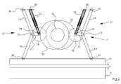
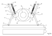
- Fig. 2 an inventive drive of the deliverable crucible is shown.
- the deliverable upper table 10 is moved over two parallel crank gear 27, which are driven by cam rollers 26 of cams 24, 25 up and down.
- the cams 24, 25 are mounted in the embodiment shown on a shaft 23 which is driven by a drive, not shown.
- Each parallel gear 27 consists of two equal-length arms, which are arranged in parallel and are connected by a coupling 21 with each other.
- the handlebars are formed in the illustrated embodiment of the actuator 22 and the upper toggle lever 18 of a toggle 17.
- the toggle mechanism is formed by the lower toggle 18 ', which is rotatably connected via a sliding bearing 20 to the upper table, and an upper toggle lever 18, the a sliding bearing 20 'is rotatably connected to the stationary machine housing 5.
- the toggle levers 18, 18 ' are connected to one another via a toggle joint 19.
- the actuator 22 is also rotatably connected at its upper end via a sliding bearing 20 'with the stationary machine housing 5 and at its lower end with the cam roller 26 and via the coupling 21 with the toggle joint 19.
- Actuator 22, coupling 21 and cam roller 26 are rotatably mounted on a common axis 28.
- Analog is in the Fig. 3 and 3a the state of upper table 10 to lower table 9 at a machine angle of 90 °, ie in the feed movement of upper table 10 to lower table 9, each in the normal state and shown with activated actuator 22.
- the distance b changes here to a higher value b 'when the actuator 22 is moved out of its final position.
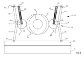
- Fig. 4 and 4a is the state of punching shown at a machine angle of 180 °. As can easily be seen, it is possible even in the punched state by activation of the actuator from its end position out, in an emergency, a distance c 'of the two tables to each other.
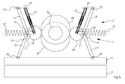
- the Fig. 6 shows a possible spring arrangement for a drive according to the invention of the deliverable crucible 10.
- the spring arrangement ensures that the cam roller 26 in each operating state of the cam plate 24 and 25 follows.
- the spring 15, 15 ' is designed as a compression spring, which is supported on the one hand on the toggle joint 19 and on the other hand on the housing.
- the compression spring is supported on the axle 28 and on the housing.
- further arrangements by means of tension springs or torsion bar arrangements are conceivable.
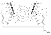
- Fig. 6a Another arrangement is in Fig. 6a shown.
- the springs 15 "and 15"' are tension springs, which are supported on the one hand on the upper table 10 and on the other on the housing.
- Fig. 7 an alternative arrangement of the actuator 22 for a drive according to the invention of the deliverable crucible is shown.
- the actuator is no longer a link of the parallel gear 27 in this embodiment, because this is now from the handlebar 29 and upper toggle 18 of a toggle 17.
- the actuator 22 is attached.
- This embodiment has the advantage that the actuator does not have to be moved. There is thus no need for a mobile power supply for the actuator.
Landscapes
- Engineering & Computer Science (AREA)
- Mechanical Engineering (AREA)
- Life Sciences & Earth Sciences (AREA)
- Forests & Forestry (AREA)
- Machines For Manufacturing Corrugated Board In Mechanical Paper-Making Processes (AREA)
- Treatment Of Fiber Materials (AREA)
- Perforating, Stamping-Out Or Severing By Means Other Than Cutting (AREA)
- Sheets, Magazines, And Separation Thereof (AREA)
Abstract
Description
- Die vorliegende Erfindung betrifft eine Bogenstanz- und -prägemaschine gemäß dem Oberbegriff von Anspruch 1.
- Als Stanzen wird das Schneiden mit in sich geschlossenen, geometrischen Zuschnittsformen bezeichnet, die kreisförmig, oval oder mehreckig sowie Fantasieformen aller Art sein können. Auch die in der Druckweiterverarbeitung geübten Praktiken wie Stanzen mit Locheisen, Ecken abstoßen und Register stanzen werden zu diesem Bereich gezählt. Die Stanzung erfolgt gegen eine Stanzunterlage oder gegen Stempel, teilweise sind es auch Schervorgänge (vgl. Druckweiterverarbeitung, Ausbildungsleitfaden für Buchbinder, Bundesverband Druck e. V. 1996, Seite 351 ff.).
- Verpackungsmaterialien aus Papier, Karton, Pappe oder Wellpappe werden hauptsächlich im Bogenformat gestanzt. Beim Stanzvorgang können zusätzlich aber auch Rilllinien oder Blindprägungen in den Nutzen eingebracht werden. Dieser komplexe Prozess macht es unabdingbar, die Bogen einzeln zu stanzen. Da es sich bei den Endprodukten um anspruchsvolle Verpackungen hinsichtlich technischer und graphischer Ausführungen handelt (etwa Verpackungen für Kosmetik, Zigaretten, Pharmazie, Lebensmittel etc.), werden besondere Anforderungen nicht nur an die Verpackungsmaterialien selbst gestellt, sondern es sind für optimale Resultate auch Stanzwerkzeuge mit geringsten Toleranzen und äußerst präzise und zuverlässig arbeitende Stanzmaschinen erforderlich.
- Diesen Ansprüchen wird das Flachbettstanzen am besten gerecht. Dabei werden die gedruckten und auf einer Palette gestapelten Bogen der Stanzmaschine zugeführt. In der Maschine erfolgt in einer Vereinzelungseinrichtung zunächst die Vereinzelung der zu stanzenden Bogen, die dann anschließend in einer Ausrichteinrichtung passgenau ausgerichtet, von einem Greiferwagen übernommen und exakt in der Stanzeinrichtung positioniert werden. Die Greiferwagen können hierbei an endlosen Ketten durch die Maschine bewegt werden oder aber durch Linearantriebe angetrieben werden.
- Die Stanzeinrichtung besteht überlicherweise aus einem mit einer Gegenplatte versehenen ruhenden Tisch und einem mit Stanz- und Rillwerkzeugen versehenen über einen Hubantrieb senkrecht zur Gegenplatte auf und ab beweglichen Tisch. Durch diese Auf-und-abbewegung wird aus den taktweise zwischen den Tischflächen hindurch geführten Bögen die Nutzen ausgestanzt und gleichzeitig die zum sauberen Falten notwendigen Rillen eingedrückt.
- In einer nachfolgenden Ausbrecheinrichtung wird der Abfall über Ausbrechwerkzeuge maschinell entfernt. Je nach Ausstattung der Maschine können schließlich die gestanzten Nutzen in einer hierfür vorgesehenen Nutzentrenneinrichtung separiert werden.
- Ein Antrieb für eine Bogenstanz- und -prägemaschine ist aus der
DE 30 44 083 A1 bekannt. Die hierin beschriebene Maschine besitzt einen festen Untertisch und einen auf und ab beweglichen Obertisch zum Stanzen von Bögen aus Papier, Pappe und dergleichen. Die Bewegung des auf und ab beweglichen Obertisches wird über Rollen realisiert, die auf zwei über dem Tisch angeordneten Exzenterwellen angeordnet sind. Der Obertisch liegt mit Federkraft gegen die Rollen auf der Exzenterwelle an. Durch eine Drehbewegung der Exzenterwellen wird der Obertisch senkrecht gegen den Untertisch bewegt. Durch den Exzenterantrieb ergibt sich im zeitlichen Verlauf eine im Wesentlichen sinusförmige Hubbewegung des Obertisches. - Ein weiterer Antrieb wird in dem amerikanischen Patent
US 4,767,393 beschrieben. Die beschriebene Stanz- und Prägemaschine besitzt einen angetriebenen Ober- und Untertisch. Der Antrieb erfolgt dabei über exzentrisch an einer Welle angeordnete Scheiben, die unmittelbar auf den Ober- und Untertisch wirken. Durch eine Drehbewegung der Wellen wird über die exzentrischen Scheiben eine gleichförmige Bewegung des Ober- und Untertisches zueinander erzielt. - Aus der
DE 33 13 790 C2 ist ein weiterer Antrieb für eine Bogenstanz- und - prägemaschine bekannt. Die Tiegelstanzpresse weist einen ersten, fest in einem Maschinengestell angeordneten Tiegel und einen zweiten, gegen den ersten zustellbaren Tiegel auf, der über vier an diesem gelenkig angreifende Kniehebel in Zustellrichtung verstellbar ist. Die Kniehebel stützen sich jeweils über ein Stützgelenk gegen das Maschinengestell ab und werden durch einen Nockentrieb beaufschlagt. Aus dieser Schrift ist es weiterhin bekannt, dass wenigstens ein Paar Stützgelenke quer zur Zustellrichtung verstellbar ist. Die Verstellbarkeit wird dadurch ermöglicht, dass die Stützgelenke jeweils über Gelenkkörper in im Maschinengestell verschiebbar gelagerte Lagerhalbschalen gelagert sind. Die in dieser Schrift offenbarte Lösung ermöglicht zwar ein Aussetzen der Stanzbewegung, jedoch wird hierbei eine Ausweichbewegung eines hoch belasteten Gelenks erforderlich. Deshalb muss im Betrieb vom Aktuator eine permanent hohe Stellkraft aufgebracht werden. Gleichzeitig erfordert eine Vorrichtung dieser Art eine hohe Stellgeschwindigkeit um schnell genug die Stanzbewegung unterbrechen zu können, da nur ein sehr kleiner zeitlicher Abstand zwischen dem Herausfahren der Greiferbrücken und der Einleitung der Stanzbewegung besteht. Diese Bedingungen, Ausweichbewegung eines hoch belasteten Gelenks und hohe Stellgeschwindigkeit führen bei der Vorrichtung gemäß derDE 33 13 790 C2 zu einer problematischen Aktuatorauswahl. - Aufgabe der vorliegenden Erfindung ist es deshalb, eine Bogenstanz- und -prägemaschine mit einem alternativen Antrieb für den zustellbaren Tiegel zu schaffen.
- Gelöst wird diese Aufgabe durch eine Bogenstanz- und -prägemaschine mit einem Antrieb des zustellbaren Tiegels gemäß den kennzeichnenden Merkmalen von Anspruch 1.
- In einer vorteilhaften Ausführungsform ist der zustellbare Tiegel über mindestens ein mehrgliedriges Koppelgetriebe, welches über eine Kurvenrolle von einer Kurvenscheibe angetrieben wird, in Abhängigkeit vom Betriebszustand verstellbar. In einer besonders bevorzugten Ausführungsform ist der zustellbare Tiegel über zwei mehrgliedrige Koppelgetriebe, welche jeweils über eine Kurvenrolle von jeweils einer Kurvenscheibe angetrieben werden, in Abhängigkeit vom Betriebszustand verstellbar. Die beiden Koppelgetriebe sind dabei einander gegenüberliegend angeordnet. Diese Lösung ist besonders vorteilhaft, um Horizontalkräfte zu kompensieren. Um zu vermeiden, dass der Tisch bei außermittiger Belastung kippt, sollte die Angriffsfläche des Koppelgetriebes auf den Tiegel entsprechend breit gewählt werden. Alternativ ist es natürlich auch möglich, drei, vier oder mehr Koppelgetriebe am Tiegel angreifen zu lassen.
- In einer bevorzugten Ausgestaltung weist das Koppelgetriebe mindestens einen Kniehebel, eine Koppel und einen Aktuator auf. Der Kniehebel ist an seinem einen Ende mit dem Maschinengestell und an seinem anderen Ende mit dem zustellbaren Tiegel über ein Drehgelenk verbunden. Die Koppel ist an ihrem einen Ende mit dem Kniegelenk des Kniehebels und mit ihrem anderen Ende mit der Achse der Kurvenrolle und dem einen Ende des Aktuators über ein Drehgelenk verbunden, wobei das andere Ende des Aktuators über ein Drehgelenk im Gehäuse gelagert ist. Mit dieser Ausgestaltung ist eine besonders einfache Verstellung des zustellbaren Tiegels in Abhängigkeit vom Betriebszustand über den Aktuator möglich.
- In einer alternativen bevorzugten Ausführungsform ist die Koppel an ihrem einen Ende mit dem Kniegelenk des Kniehebels und mit ihrem anderen Ende mit der Achse der Kurvenrolle und dem einen Ende eines weiteren Hebels über ein Drehgelenk verbunden, wobei das andere Ende des weiteren Hebels mit einem Aktuator verbunden ist. Diese Ausführungsform hat den Vorteil, dass der Aktuator nur in einer einzigen Wirkrichtung bewegt wird und nicht schwenken muss.
- In einer vorteilhaften Ausführungsform liegt die Achse der Kurvenrolle außerhalb des Bewegungsbereiches des Kniegelenks des Kniehebels. Das Koppelgetriebe mit Kurvenrolle ist über mindestens eine entsprechende Federanordnung in Richtung auf die Kurvenscheibe belastet. Hierdurch wird zum einen sowohl ein ständiger Kontakt mit dem Antrieb als auch der notwendige Hub für eine Bewegung des Tiegels gewährleistet.
- In bevorzugten Ausführungsformen ist der Aktuator als Pneumatikzylinder oder Hydraulikzylinder oder als elektromechanische Lösung in Form einer Gewindespindel ausgebildet. Hierdurch wird eine einfache und zuverlässige Bewegung des Aktuator gewährleistet, so dass die Kurvenrolle aus der unmittelbaren horizontalen Wirkungslinie zwischen Kniegelenk und Kurvenscheibe herausgeführt wird, was zum Einknicken des Kniegelenks führt, was den Stanzvorgang augenblicklich unterbricht.
- In den Zeichnungen sind bevorzugte Ausführungen der erfindungsgemäßen Bogenstanz-und -prägemaschine dargestellt.
- Es zeigen:
- Fig. 1
- den prinzipiellen Aufbau einer Bogenstanz- und -prägemaschine in schematischer Darstellung
- Fig. 2
- einen erfindungsgemäßen Antrieb des zustellbaren Tiegels bei 0° Maschinenwinkel ohne aktivierten Aktuator
- Fig. 2a
- einen erfindungsgemäßen Antrieb des zustellbaren Tiegels bei 0° Maschinenwinkel und aktiviertem Aktuator
- Fig. 3
- einen erfindungsgemäßen Antrieb des zustellbaren Tiegels bei 90° Maschinenwinkel ohne aktivierten Aktuator
- Fig. 3a
- einen erfindungsgemäßen Antrieb des zustellbaren Tiegels bei 90° Maschinenwinkel und aktiviertem Aktuator
- Fig. 4
- einen erfindungsgemäßen Antrieb des zustellbaren Tiegels bei 180° Maschinenwinkel ohne aktivierten Aktuator
- Fig. 4a
- einen erfindungsgemäßen Antrieb des zustellbaren Tiegels bei 180° Maschinenwinkel und aktiviertem Aktuator
- Fig. 5
- einen erfindungsgemäßen Antrieb des zustellbaren Tiegels bei 270° Maschinenwinkel ohne aktivierten Aktuator
- Fig. 5a
- einen erfindungsgemäßen Antrieb des zustellbaren Tiegels bei 270° Maschinenwinkel und aktiviertem Aktuator
- Fig. 6, 6a
- zeigen mögliche Federanordnungen für einen erfindungsgemäßen Antrieb des zustellbaren Tiegels
- Fig. 7
- zeigt eine alternative Anordnung des Aktuators für einen erfindungsgemäßen Antrieb des zustellbaren Tiegels
- In
Fig. 1 ist der prinzipielle Aufbau einer Bogenstanz- und -prägemaschine 100 zum Stanzen, Ausbrechen und Ablegen von Bögen aus Papier, Pappe und dergleichen dargestellt. Die Stanz- und Prägemaschine 100 besitzt einen Anleger 1, eine Stanzstation 2, eine Ausbrechstation 3 und einen Ausleger 4, die von einem gemeinsamen Maschinengehäuse 5 getragen und umschlossen werden. - Die Bogen 6 werden durch einen Anleger 1 von einem Stapel vereinzelt und über einen Zuführtisch 16 der Bogenstanz- und -prägemaschine 100 zugeführt und von Greifern an ihrer Vorderkante ergriffen und intermittierend in Bogenförderrichtung F durch die verschiedenen Stationen 2, 3 und 4 der Stanz- und Prägemaschine 100 hindurchgezogen. Die Greifer sind hierbei an Greiferstangen 8 und diese wiederum an einem Transportsystem 7 befestigt.
- Die Stanzstation 2 besteht aus einem Untertisch 9 und einem Obertisch 10. Der Untertisch 9 ist fest im Maschinengestell gelagert und mit einer nicht näher dargstellten Gegenplatte zu den Stanzmessern versehen. Der Obertisch ist vertikal hin- und her bewegbar gelagert und ist mit den Stanz- und Rillmessern versehen.
- Die Greifer an den Greiferstangen 8 transportieren den Bogen 6 von der Stanz- und Prägestation 2 in die nachfolgende Ausbrechstation 3, die mit Ausbrechwerkzeugen ausgestattet ist. In der Ausbrechstation 3 werden mit Hilfe der Ausbrechwerkzeuge die nicht benötigten Abfallstücke aus dem Bogen 6 nach unten herausgestoßen, wodurch die Abfallstücke 11 in einen unter der Station eingeschobenen behälterartigen Wagen 12 fallen.
- Von der Ausbrechstation 3 gelangt der Bogen in den Ausleger 4, wo der Bogen entweder nur einfach abgelegt wird, oder aber gleichzeitig eine Trennung in einzelne Nutzen erfolgt. Der Ausleger 4 kann auch eine Palette 13 enthalten, auf der die einzelnen Bögen in Form eines Stapels 14 aufgestapelt werden, so dass nach Erreichen einer bestimmten Stapelhöhe die Paletten mit den aufgestapelten Bögen 14 aus dem Bereich der Stanz- und -prägemaschine 100 weggefahren werden können.
- In
Fig. 2 ist ein erfindungsgemäßer Antrieb des zustellbaren Tiegels dargestellt. In der schematischen Darstellung ist der Untertisch 9 fest im inFig. 2 nicht näher dargestellten Maschinengehäuse 5 gelagert. Der zustellbare Obertisch 10 wird über zwei Parallelkurbelgetriebe 27, welche über Kurvenrollen 26 von Kurvenscheiben 24, 25 angetrieben werden auf und ab bewegt. Die Kurvenscheiben 24, 25 sind in der gezeigten Ausführung auf einer Welle 23 gelagert, die von einem nicht dargestellten Antrieb angetrieben wird. Jedes Parallelgetriebe 27 besteht aus zwei gleich langen Lenkern, die parallel angeordnet sind und durch eine Koppel 21 miteinander verbunden sind. Die Lenker werden in der dargestellten Ausführungsform gebildet vom Aktuator 22 und dem oberen Kniehebel 18 eines Kniehebelgetriebes 17. Das Kniehebelgetriebe wird gebildet vom unteren Kniehebel 18', der über ein Gleitlager 20 drehbar mit dem Obertisch verbunden ist, und einem oberen Kniehebel 18, der über ein Gleitlager 20' mit dem feststehenden Maschinengehäuse 5 drehbar verbunden ist. An ihrem jeweiligen anderen Ende sind die Kniehebel 18, 18' über ein Kniehebelgelenk 19 miteinander verbunden. Der Aktuator 22 ist an seinem oberen Ende ebenfalls über ein Gleitlager 20' mit dem feststehenden Maschinengehäuse 5 drehbar verbunden und an seinem unteren Ende mit der Kurvenrolle 26 und über die Koppel 21 mit dem Kniehebelgelenk 19. Aktuator 22, Koppel 21 und Kurvenrolle 26 sind dabei auf einer gemeinsamen Achse 28 drehbar angeordnet. Bei der Darstellung inFig. 2 handelt es sich um die Stellung des Obertisches 10 zum Untertisch 9 beim Maschinenwinkel 0°, also in der oberen Totlage. Der Abstand a der beiden Tische zueinander ist somit der Maximalabstand bei nicht aktiviertem Aktuator 22. Der Abstand a' der beiden Tische zueinander bei aktiviertem Aktuator 22 ist inFig. 2a dargestellt. Der Aktuator 22 wurde aus seiner Endlage herausbewegt. Dies führt dazu, dass die Kurvenrolle 26 aus der unmittelbaren horizontalen Wirkungslinie zwischen Kniehebelgelenk 19 und Kurvenscheibe 24 herausgeführt wird. Hierdurch knicken die Kniehebel 18, 18' ein und der Abstand a' zwischen Obertisch und Untertisch wird vergrößert. Für eine Notstop-Situation kann der Aktuator so ausgeprägt sein, dass er bei Energieausfall automatisch aus seiner Endlager herausfährt und damit den Ausknickvorgang einleitet. Damit ist gewährleistet, dass auch im Falle eines kompletten Ausfalls der Energieversorgung ein Maschinenschaden verhindert wird. - Analog ist in den
Fig. 3 und3a der Zustand von Obertisch 10 zu Untertisch 9 bei einem Maschinenwinkel von 90°, also in der Zustellbewegung von Obertisch 10 zu Untertisch 9, jeweils im Normalzustand und mit aktiviertem Aktuator 22 dargestellt. Wie man sieht, ändert sich auch hier der Abstand b auf einen höheren Wert b', wenn der Aktuator 22 aus seiner Endlage herausbewegt wird. - In
Fig. 3 ist sehr gut zu erkennen, dass der Kniehebelwinkel deutlich steiler ist, wodurch die notwendige Kraftübertragung ermöglicht wird. - In den
Fig. 4 und4a ist der Zustand des Stanzens dargestellt bei einem Maschinenwinkel von 180°. Wie man leicht erkennt, ist es selbst in Stanzzustand durch Aktivierung des Aktuators aus seiner Endlage heraus möglich, im Notfall einen Abstand c' der beiden Tische zueinander herzustellen. - In den
Fig. 5 und5a ist der Zustand bei einem Maschinenwinkel von 270° dargestellt, der Obertisch 10 bewegt sich also bereits wieder vom Untertisch 9 weg. - Die
Fig. 6 zeigt eine mögliche Federanordnung für einen erfindungsgemäßen Antrieb des zustellbaren Tiegels 10. Durch die Federanordnung wird sichergestellt, dass die Kurvenrolle 26 in jedem Betriebszustand der Kurvenscheibe 24 bzw. 25 folgt. In der dargestellten Ausführungsform ist die Feder 15, 15' als Druckfeder ausgeführt, die sich einerseits am Kniehebelgelenk 19 und andererseits am Gehäuse abstützt. Natürlich ist es auch denkbar, dass sich die Druckfeder an der Achse 28 und am Gehäuse abstützt. Weiterhin sind weitere Anordnungen mittels Zugfedern oder Drehstabfederanordnungen denkbar. - Eine weitere Anordnung ist in
Fig. 6a dargestellt. In dieser Ausführungsform handelt es sich bei den Federn 15" und 15"' um Zugfedern, die sich zum einen am Obertisch 10 und zum anderen am Gehäuse abstützen. - In
Fig 7 . ist eine alternative Anordnung des Aktuators 22 für einen erfindungsgemäßen Antrieb des zustellbaren Tiegels dargestellt. Der Aktuator ist in diesem Ausführungsbeispiel nicht mehr ein Lenker des Parallelgetriebes 27, denn dieses wird nun aus dem Lenker 29 und oberen Kniehebel 18 eines Kniehebelgetriebes 17. Am oberen Ende des Lenkers 29 ist dann der Aktuator 22 befestigt. Diese Ausführungsform hat den Vorteil, dass der Aktuator nicht mitbewegt werden muss. Es ist somit keine bewegliche Energieversorgung für den Aktuator notwendig. -
1 Anleger 20, 20' Gleitlager 2 Stanzstation 21 Koppel 3 Ausbrechstation 22 Aktuator 4 Ausleger 23 Antriebswelle 5 Maschinengehäuse 24 Kurvenscheibe 6 Bogen 25 Kurvenscheibe 7 Transportsystem 26 Kurvenrolle 8 Greiferstangen 27 Parallelkurbelgetriebe 9 Untertisch 28 Achse 10 Obertisch 29 Lenker 11 Abfallstücke 100 Bogenstanz- und 12 Wagen -prägemaschine 13 Palette 14 Stapel F Bogenförderrichtung 15, 15' Feder 15", 15"' 16 Zuführtisch a, a' Tischabstand 17 Kniehebelgetriebe b, b' Tischabstand 18, 18' Kniehebel c, c' Tischabstand 19 Kniehebelgelenk d, d' Tischabstand
Claims (10)
- Bogenstanz- und -prägemaschine mit mindestens einer Stanzstation (2) und einer Transportvorrichtung für die zu stanzenden Bogen, wobei die Stanzstation (2) einen ersten fest in einem Maschinengestell angeordneten Tiegel und einen zweiten, gegen den ersten Tiegel zustellbaren Tiegel aufweist,
dadurch gekennzeichnet,
dass der zustellbare Tiegel (10) über mindestens ein mehrgliedriges Koppelgetriebe (27), welches über eine Kurvenrolle (26) von einer Kurvenscheibe (24, 25) angetrieben wird, in Abhängigkeit vom Betriebszustand verstellbar ist. - Bogenstanz- und -prägemaschine nach Anspruch 1,
dadurch gekennzeichnet,
dass der zustellbare Tiegel (10) über zwei mehrgliedrige Koppelgetriebe (27), welche jeweils über eine Kurvenrolle (26) von jeweils einer Kurvenscheibe (24, 25) angetrieben werden, in Abhängigkeit vom Betriebszustand verstellbar ist, wobei die Koppelgetriebe (27) einander gegenüberliegend angeordnet sind. - Bogenstanz- und -prägemaschine nach Anspruch 1 oder 2,
dadurch gekennzeichnet,
dass das Koppelgetriebe mindestens einen Kniehebel (18, 18'), eine Koppel (21) und einen Aktuator (22) aufweist. - Bogenstanz- und -prägemaschine nach Anspruch 2,
dadurch gekennzeichnet,
dass der Kniehebel (18, 18') an seinem einen Ende mit dem Maschinengestell und an seinem anderen Ende mit dem zustellbaren Tiegel (10) über ein Drehgelenk (20, 20') verbunden ist. - Bogenstanz- und -prägemaschine nach Anspruch 3 oder 4,
dadurch gekennzeichnet,
dass die Koppel (21) an ihrem einen Ende mit dem Kniegelenk (19) des Kniehebels (18, 18') und mit ihrem anderen Ende mit der Achse der Kurvenrolle (26) und dem einen Ende des Aktuators über ein Drehgelenk verbunden ist, wobei das andere Ende des Aktuators (22) über ein Drehgelenk (20') fest im Gehäuse (5) gelagert ist. - Bogenstanz- und -prägemaschine nach Anspruch 3 oder 4,
dadurch gekennzeichnet,
dass die Koppel (21) an ihrem einen Ende mit dem Kniegelenk des Kniehebels (18, 18') und mit ihrem anderen Ende mit der Achse (28) der Kurvenrolle (26) und dem einen Ende eines weiteren Hebels über ein Drehgelenk verbunden ist, wobei das andere Ende des weiteren Hebels mit einem Aktuator (22) verbunden ist. - Bogenstanz- und -prägemaschine nach einem der Ansprüche 3 bi 6,
dadurch gekennzeichnet,
dass die Achse der Kurvenrolle (26) außerhalb des Bewegungsbereiches des Kniegelenks des Kniehebels (18, 18') liegt. - Bogenstanz- und -prägemaschine nach einem der Ansprüche 1 bis 7,
dadurch gekennzeichnet,
dass das Koppelgetriebe mit Kurvenrolle (26) über mindestens eine Feder (15, 15') in Richtung auf die Kurvenscheibe (24, 25) belastet wird. - Bogenstanz- und -prägemaschine nach einem der Ansprüche 3 bis 8,
dadurch gekennzeichnet,
dass der Aktuator (22) im Falle eines Notstops aus seiner Endlage heraus bewegbar ist, so dass die Kurvenrolle (26) aus der unmittelbaren horizontalen Wirkungslinie zwischen Kniegelenk und Kurvenscheibe (24, 25) herausgeführt wird, wodurch das Kniegelenk einknickt und der Stanzvorgang unterbrochen wird. - Bogenstanz- und -prägemaschine nach einem der Ansprüche 3 bis 9,
dadurch gekennzeichnet,
dass der Aktuator (22) ein Pneumatikzylinder oder ein Hydraulikzylinder oder eine Gewindespindel ist.
Applications Claiming Priority (1)
| Application Number | Priority Date | Filing Date | Title |
|---|---|---|---|
| DE102007012639A DE102007012639A1 (de) | 2007-03-16 | 2007-03-16 | Bogenstanz- und prägemaschine |
Publications (2)
| Publication Number | Publication Date |
|---|---|
| EP1970174A1 true EP1970174A1 (de) | 2008-09-17 |
| EP1970174B1 EP1970174B1 (de) | 2011-08-24 |
Family
ID=39495142
Family Applications (1)
| Application Number | Title | Priority Date | Filing Date |
|---|---|---|---|
| EP08101860A Not-in-force EP1970174B1 (de) | 2007-03-16 | 2008-02-22 | Bogenstanz- und -prägemaschine |
Country Status (4)
| Country | Link |
|---|---|
| EP (1) | EP1970174B1 (de) |
| CN (1) | CN101264610A (de) |
| AT (1) | ATE521460T1 (de) |
| DE (1) | DE102007012639A1 (de) |
Cited By (1)
| Publication number | Priority date | Publication date | Assignee | Title |
|---|---|---|---|---|
| JP2011000628A (ja) * | 2009-06-22 | 2011-01-06 | Yamada Dobby Co Ltd | プレス機 |
Families Citing this family (6)
| Publication number | Priority date | Publication date | Assignee | Title |
|---|---|---|---|---|
| DE102010024778A1 (de) | 2010-06-23 | 2011-12-29 | Heidelberger Druckmaschinen Ag | Ablage- und Nutzentrennstation für eine Bogenstanzmaschine |
| TWI515120B (zh) * | 2010-09-22 | 2016-01-01 | 巴柏斯特合資公司 | 包含平板壓機的打印機 |
| DE102011118905B4 (de) * | 2010-12-16 | 2025-03-13 | Masterwork Group Co., Ltd. | Bearbeitungsstation für eine Stanzmaschine |
| DE102013015838A1 (de) | 2012-10-16 | 2014-04-17 | Heidelberger Druckmaschinen Aktiengesellschaft | Abschirmung an einer Bogen verarbeitenden Maschine, z. B. Stanze oder Druckmaschine, insbesondere im Bereich des Auslegers |
| CN106739460A (zh) * | 2017-01-04 | 2017-05-31 | 玉田县诚远印刷包装机械有限公司 | 平压平自动模切烫印机的驱动机构 |
| CN108437543A (zh) * | 2018-03-15 | 2018-08-24 | 东莞市美盈森环保科技有限公司 | 一种瓦楞纸盒成型工艺 |
Citations (4)
| Publication number | Priority date | Publication date | Assignee | Title |
|---|---|---|---|---|
| DE3044083A1 (de) | 1980-11-24 | 1982-09-09 | Wupa-Maschinenfabrik GmbH, 4057 Brüggen | Stanzeinrichtung |
| DE3313790A1 (de) * | 1982-04-15 | 1983-10-27 | Bobst S.A., 1001 Lausanne | Tiegelstanzpresse |
| US4767393A (en) | 1983-07-22 | 1988-08-30 | Smith Edwin K | High speed platen-type die cutter |
| GB2396581A (en) * | 2002-12-27 | 2004-06-30 | Tian-Sheng Liu | Main drive and convert mechanism in a platen press with a flat auto-die for cutting and gilding |
Family Cites Families (2)
| Publication number | Priority date | Publication date | Assignee | Title |
|---|---|---|---|---|
| DE3011090A1 (de) * | 1980-03-22 | 1981-10-01 | Rahdener Maschinenfabrik August Kolbus Gmbh & Co Kg, 4993 Rahden | Pressstempelantrieb fuer papierschneidemaschinen |
| DE3012486C2 (de) * | 1980-03-31 | 1985-04-18 | Jürgen 1000 Berlin Schulz | Vorrichtung nach Art einer Stanze oder Presse |
-
2007
- 2007-03-16 DE DE102007012639A patent/DE102007012639A1/de not_active Withdrawn
-
2008
- 2008-02-22 AT AT08101860T patent/ATE521460T1/de active
- 2008-02-22 EP EP08101860A patent/EP1970174B1/de not_active Not-in-force
- 2008-03-14 CN CNA2008100836535A patent/CN101264610A/zh active Pending
Patent Citations (5)
| Publication number | Priority date | Publication date | Assignee | Title |
|---|---|---|---|---|
| DE3044083A1 (de) | 1980-11-24 | 1982-09-09 | Wupa-Maschinenfabrik GmbH, 4057 Brüggen | Stanzeinrichtung |
| DE3313790A1 (de) * | 1982-04-15 | 1983-10-27 | Bobst S.A., 1001 Lausanne | Tiegelstanzpresse |
| DE3313790C2 (de) | 1982-04-15 | 1987-01-22 | Bobst S.A., Lausanne | Tiegelstanzpresse |
| US4767393A (en) | 1983-07-22 | 1988-08-30 | Smith Edwin K | High speed platen-type die cutter |
| GB2396581A (en) * | 2002-12-27 | 2004-06-30 | Tian-Sheng Liu | Main drive and convert mechanism in a platen press with a flat auto-die for cutting and gilding |
Non-Patent Citations (1)
| Title |
|---|
| BUNDESVERBAND DRUCK E. V., DRUCKWEITERVERARBEITUNG, AUSBILDUNGSLEITFADEN FÜR BUCHBINDER, 1996, pages 351 |
Cited By (1)
| Publication number | Priority date | Publication date | Assignee | Title |
|---|---|---|---|---|
| JP2011000628A (ja) * | 2009-06-22 | 2011-01-06 | Yamada Dobby Co Ltd | プレス機 |
Also Published As
| Publication number | Publication date |
|---|---|
| EP1970174B1 (de) | 2011-08-24 |
| DE102007012639A1 (de) | 2008-09-18 |
| ATE521460T1 (de) | 2011-09-15 |
| CN101264610A (zh) | 2008-09-17 |
Similar Documents
| Publication | Publication Date | Title |
|---|---|---|
| EP1970173B1 (de) | Bogenstanz- und -prägemaschine | |
| EP2399715B1 (de) | Ablage- und Nutzentrennstation für eine Bogenstanzmaschine | |
| EP1914049B1 (de) | Flachbett-Bogenstanzmaschine | |
| EP1882564B1 (de) | Bogenstanz- und -prägemaschine mit regulierbarem Stanz- oder Prägedruck | |
| EP1882562B1 (de) | Bogenstanz- und -prägemaschine | |
| DE102007014314A1 (de) | Bogenstanz- und -prägemaschine mit hydraulischem Antrieb | |
| EP1970174B1 (de) | Bogenstanz- und -prägemaschine | |
| EP2452790B1 (de) | Bearbeitungsstation für eine Stanzmaschine und Verfahren zur Probebogenauslage | |
| EP2397285B1 (de) | Stanz- und/oder Prägestation einer Bogenstanzmaschine | |
| EP2080600A1 (de) | Flachbettstanzmodul zum Stanzen eines Bedruckstoffes und Flachbettstanze | |
| EP2722298A1 (de) | Flachbett-Bogenstanz- und/oder -prägemaschine mit Überwachungssensor und Verfahren zum Schnellabschalten einer solchen Maschine | |
| EP2087972A1 (de) | Vorrichtung zum Stanzen | |
| DE102011118283A1 (de) | Bearbeitungsstation einer Bogenstanzmaschine mit Stellmotor | |
| EP2653420B1 (de) | Verfahren zur Bogenübergabe und Stanzmaschine mit Greifer-Transportsystem | |
| DE102012019051B4 (de) | Transportvorrichtung für Bogen mit obenliegender Blasluftkammer | |
| DE102008011051A1 (de) | Bogenstanz- und -prägemaschine | |
| EP2719508B1 (de) | Antriebsvorrichtung und Stanzmaschine mit einer solchen Antriebsvorrichtung | |
| DE102011118905B4 (de) | Bearbeitungsstation für eine Stanzmaschine | |
| DE102004029037A1 (de) | Vorrichtung zum Bearbeiten von Substraten | |
| EP2412497B1 (de) | Vorrichtung und Verfahen zum Wechseln des Oberwerkzeugs einer Stanzstation einer Bogenstanzmaschine | |
| EP1970176A1 (de) | Bogenstanz- und -prägemaschine | |
| EP2554345B1 (de) | Bogenstanz- und/oder -prägestation mit druckluftbetätigtem Schließrahmen | |
| EP1882565A2 (de) | Verfahren zum Stanzen und Bogenstanz- und -prägemaschine | |
| DE102009058591A1 (de) | Bogenstanz- und -/oder Prägemaschine mit einer Vorrichtung zum Absenken der Greiferbrücke | |
| DE102013006348A1 (de) | Oberwerkzeug, Bearbeitungsstation und Verfahren zum Ausbrechen |
Legal Events
| Date | Code | Title | Description |
|---|---|---|---|
| PUAI | Public reference made under article 153(3) epc to a published international application that has entered the european phase |
Free format text: ORIGINAL CODE: 0009012 |
|
| AK | Designated contracting states |
Kind code of ref document: A1 Designated state(s): AT BE BG CH CY CZ DE DK EE ES FI FR GB GR HR HU IE IS IT LI LT LU LV MC MT NL NO PL PT RO SE SI SK TR |
|
| AX | Request for extension of the european patent |
Extension state: AL BA MK RS |
|
| 17P | Request for examination filed |
Effective date: 20090317 |
|
| AKX | Designation fees paid |
Designated state(s): AT BE BG CH CY CZ DE DK EE ES FI FR GB GR HR HU IE IS IT LI LT LU LV MC MT NL NO PL PT RO SE SI SK TR |
|
| 17Q | First examination report despatched |
Effective date: 20090424 |
|
| GRAP | Despatch of communication of intention to grant a patent |
Free format text: ORIGINAL CODE: EPIDOSNIGR1 |
|
| GRAS | Grant fee paid |
Free format text: ORIGINAL CODE: EPIDOSNIGR3 |
|
| GRAA | (expected) grant |
Free format text: ORIGINAL CODE: 0009210 |
|
| AK | Designated contracting states |
Kind code of ref document: B1 Designated state(s): AT BE BG CH CY CZ DE DK EE ES FI FR GB GR HR HU IE IS IT LI LT LU LV MC MT NL NO PL PT RO SE SI SK TR |
|
| REG | Reference to a national code |
Ref country code: GB Ref legal event code: FG4D Free format text: NOT ENGLISH |
|
| REG | Reference to a national code |
Ref country code: CH Ref legal event code: EP |
|
| REG | Reference to a national code |
Ref country code: IE Ref legal event code: FG4D Free format text: LANGUAGE OF EP DOCUMENT: GERMAN |
|
| REG | Reference to a national code |
Ref country code: DE Ref legal event code: R096 Ref document number: 502008004576 Country of ref document: DE Effective date: 20111027 |
|
| REG | Reference to a national code |
Ref country code: NL Ref legal event code: VDEP Effective date: 20110824 |
|
| LTIE | Lt: invalidation of european patent or patent extension |
Effective date: 20110824 |
|
| PG25 | Lapsed in a contracting state [announced via postgrant information from national office to epo] |
Ref country code: FI Free format text: LAPSE BECAUSE OF FAILURE TO SUBMIT A TRANSLATION OF THE DESCRIPTION OR TO PAY THE FEE WITHIN THE PRESCRIBED TIME-LIMIT Effective date: 20110824 Ref country code: PT Free format text: LAPSE BECAUSE OF FAILURE TO SUBMIT A TRANSLATION OF THE DESCRIPTION OR TO PAY THE FEE WITHIN THE PRESCRIBED TIME-LIMIT Effective date: 20111226 Ref country code: SE Free format text: LAPSE BECAUSE OF FAILURE TO SUBMIT A TRANSLATION OF THE DESCRIPTION OR TO PAY THE FEE WITHIN THE PRESCRIBED TIME-LIMIT Effective date: 20110824 Ref country code: IS Free format text: LAPSE BECAUSE OF FAILURE TO SUBMIT A TRANSLATION OF THE DESCRIPTION OR TO PAY THE FEE WITHIN THE PRESCRIBED TIME-LIMIT Effective date: 20111224 Ref country code: LT Free format text: LAPSE BECAUSE OF FAILURE TO SUBMIT A TRANSLATION OF THE DESCRIPTION OR TO PAY THE FEE WITHIN THE PRESCRIBED TIME-LIMIT Effective date: 20110824 Ref country code: NL Free format text: LAPSE BECAUSE OF FAILURE TO SUBMIT A TRANSLATION OF THE DESCRIPTION OR TO PAY THE FEE WITHIN THE PRESCRIBED TIME-LIMIT Effective date: 20110824 Ref country code: NO Free format text: LAPSE BECAUSE OF FAILURE TO SUBMIT A TRANSLATION OF THE DESCRIPTION OR TO PAY THE FEE WITHIN THE PRESCRIBED TIME-LIMIT Effective date: 20111124 Ref country code: HR Free format text: LAPSE BECAUSE OF FAILURE TO SUBMIT A TRANSLATION OF THE DESCRIPTION OR TO PAY THE FEE WITHIN THE PRESCRIBED TIME-LIMIT Effective date: 20110824 |
|
| PG25 | Lapsed in a contracting state [announced via postgrant information from national office to epo] |
Ref country code: LV Free format text: LAPSE BECAUSE OF FAILURE TO SUBMIT A TRANSLATION OF THE DESCRIPTION OR TO PAY THE FEE WITHIN THE PRESCRIBED TIME-LIMIT Effective date: 20110824 Ref country code: SI Free format text: LAPSE BECAUSE OF FAILURE TO SUBMIT A TRANSLATION OF THE DESCRIPTION OR TO PAY THE FEE WITHIN THE PRESCRIBED TIME-LIMIT Effective date: 20110824 Ref country code: GR Free format text: LAPSE BECAUSE OF FAILURE TO SUBMIT A TRANSLATION OF THE DESCRIPTION OR TO PAY THE FEE WITHIN THE PRESCRIBED TIME-LIMIT Effective date: 20111125 Ref country code: PL Free format text: LAPSE BECAUSE OF FAILURE TO SUBMIT A TRANSLATION OF THE DESCRIPTION OR TO PAY THE FEE WITHIN THE PRESCRIBED TIME-LIMIT Effective date: 20110824 Ref country code: CY Free format text: LAPSE BECAUSE OF FAILURE TO SUBMIT A TRANSLATION OF THE DESCRIPTION OR TO PAY THE FEE WITHIN THE PRESCRIBED TIME-LIMIT Effective date: 20110824 |
|
| REG | Reference to a national code |
Ref country code: IE Ref legal event code: FD4D |
|
| PG25 | Lapsed in a contracting state [announced via postgrant information from national office to epo] |
Ref country code: CZ Free format text: LAPSE BECAUSE OF FAILURE TO SUBMIT A TRANSLATION OF THE DESCRIPTION OR TO PAY THE FEE WITHIN THE PRESCRIBED TIME-LIMIT Effective date: 20110824 Ref country code: IE Free format text: LAPSE BECAUSE OF FAILURE TO SUBMIT A TRANSLATION OF THE DESCRIPTION OR TO PAY THE FEE WITHIN THE PRESCRIBED TIME-LIMIT Effective date: 20110824 Ref country code: SK Free format text: LAPSE BECAUSE OF FAILURE TO SUBMIT A TRANSLATION OF THE DESCRIPTION OR TO PAY THE FEE WITHIN THE PRESCRIBED TIME-LIMIT Effective date: 20110824 |
|
| PG25 | Lapsed in a contracting state [announced via postgrant information from national office to epo] |
Ref country code: RO Free format text: LAPSE BECAUSE OF FAILURE TO SUBMIT A TRANSLATION OF THE DESCRIPTION OR TO PAY THE FEE WITHIN THE PRESCRIBED TIME-LIMIT Effective date: 20110824 Ref country code: IT Free format text: LAPSE BECAUSE OF FAILURE TO SUBMIT A TRANSLATION OF THE DESCRIPTION OR TO PAY THE FEE WITHIN THE PRESCRIBED TIME-LIMIT Effective date: 20110824 Ref country code: EE Free format text: LAPSE BECAUSE OF FAILURE TO SUBMIT A TRANSLATION OF THE DESCRIPTION OR TO PAY THE FEE WITHIN THE PRESCRIBED TIME-LIMIT Effective date: 20110824 |
|
| PG25 | Lapsed in a contracting state [announced via postgrant information from national office to epo] |
Ref country code: DK Free format text: LAPSE BECAUSE OF FAILURE TO SUBMIT A TRANSLATION OF THE DESCRIPTION OR TO PAY THE FEE WITHIN THE PRESCRIBED TIME-LIMIT Effective date: 20110824 |
|
| PLBE | No opposition filed within time limit |
Free format text: ORIGINAL CODE: 0009261 |
|
| STAA | Information on the status of an ep patent application or granted ep patent |
Free format text: STATUS: NO OPPOSITION FILED WITHIN TIME LIMIT |
|
| 26N | No opposition filed |
Effective date: 20120525 |
|
| BERE | Be: lapsed |
Owner name: HEIDELBERGER DRUCKMASCHINEN A.G. Effective date: 20120228 |
|
| REG | Reference to a national code |
Ref country code: DE Ref legal event code: R097 Ref document number: 502008004576 Country of ref document: DE Effective date: 20120525 |
|
| PG25 | Lapsed in a contracting state [announced via postgrant information from national office to epo] |
Ref country code: MC Free format text: LAPSE BECAUSE OF NON-PAYMENT OF DUE FEES Effective date: 20120229 |
|
| GBPC | Gb: european patent ceased through non-payment of renewal fee |
Effective date: 20120222 |
|
| REG | Reference to a national code |
Ref country code: FR Ref legal event code: ST Effective date: 20121031 |
|
| PG25 | Lapsed in a contracting state [announced via postgrant information from national office to epo] |
Ref country code: BE Free format text: LAPSE BECAUSE OF NON-PAYMENT OF DUE FEES Effective date: 20120228 |
|
| PG25 | Lapsed in a contracting state [announced via postgrant information from national office to epo] |
Ref country code: FR Free format text: LAPSE BECAUSE OF NON-PAYMENT OF DUE FEES Effective date: 20120229 Ref country code: GB Free format text: LAPSE BECAUSE OF NON-PAYMENT OF DUE FEES Effective date: 20120222 |
|
| PG25 | Lapsed in a contracting state [announced via postgrant information from national office to epo] |
Ref country code: ES Free format text: LAPSE BECAUSE OF FAILURE TO SUBMIT A TRANSLATION OF THE DESCRIPTION OR TO PAY THE FEE WITHIN THE PRESCRIBED TIME-LIMIT Effective date: 20111205 |
|
| PG25 | Lapsed in a contracting state [announced via postgrant information from national office to epo] |
Ref country code: BG Free format text: LAPSE BECAUSE OF FAILURE TO SUBMIT A TRANSLATION OF THE DESCRIPTION OR TO PAY THE FEE WITHIN THE PRESCRIBED TIME-LIMIT Effective date: 20111124 |
|
| PG25 | Lapsed in a contracting state [announced via postgrant information from national office to epo] |
Ref country code: MT Free format text: LAPSE BECAUSE OF FAILURE TO SUBMIT A TRANSLATION OF THE DESCRIPTION OR TO PAY THE FEE WITHIN THE PRESCRIBED TIME-LIMIT Effective date: 20110824 |
|
| REG | Reference to a national code |
Ref country code: AT Ref legal event code: MM01 Ref document number: 521460 Country of ref document: AT Kind code of ref document: T Effective date: 20130222 |
|
| PG25 | Lapsed in a contracting state [announced via postgrant information from national office to epo] |
Ref country code: TR Free format text: LAPSE BECAUSE OF FAILURE TO SUBMIT A TRANSLATION OF THE DESCRIPTION OR TO PAY THE FEE WITHIN THE PRESCRIBED TIME-LIMIT Effective date: 20110824 |
|
| PG25 | Lapsed in a contracting state [announced via postgrant information from national office to epo] |
Ref country code: LU Free format text: LAPSE BECAUSE OF NON-PAYMENT OF DUE FEES Effective date: 20120222 Ref country code: AT Free format text: LAPSE BECAUSE OF NON-PAYMENT OF DUE FEES Effective date: 20130222 |
|
| PG25 | Lapsed in a contracting state [announced via postgrant information from national office to epo] |
Ref country code: HU Free format text: LAPSE BECAUSE OF FAILURE TO SUBMIT A TRANSLATION OF THE DESCRIPTION OR TO PAY THE FEE WITHIN THE PRESCRIBED TIME-LIMIT Effective date: 20080222 |
|
| REG | Reference to a national code |
Ref country code: DE Ref legal event code: R081 Ref document number: 502008004576 Country of ref document: DE Owner name: MASTERWORK MACHINERY CO., LTD., CN Free format text: FORMER OWNER: HEIDELBERGER DRUCKMASCHINEN AG, 69115 HEIDELBERG, DE Effective date: 20150402 |
|
| REG | Reference to a national code |
Ref country code: CH Ref legal event code: NV Representative=s name: GLN S.A., CH Ref country code: CH Ref legal event code: PUE Owner name: MASTERWORK MACHINERY CO., LTD., CN Free format text: FORMER OWNER: HEIDELBERGER DRUCKMASCHINEN AG, DE |
|
| REG | Reference to a national code |
Ref country code: CH Ref legal event code: PFA Owner name: MASTERWORK MACHINERY CO., LTD., CN Free format text: FORMER OWNER: MASTERWORK MACHINERY CO., LTD., CN |
|
| REG | Reference to a national code |
Ref country code: CH Ref legal event code: NV Representative=s name: BOVARD SA NEUCHATEL CONSEILS EN PROPRIETE INTE, CH |
|
| PGFP | Annual fee paid to national office [announced via postgrant information from national office to epo] |
Ref country code: DE Payment date: 20220502 Year of fee payment: 15 |
|
| PGFP | Annual fee paid to national office [announced via postgrant information from national office to epo] |
Ref country code: CH Payment date: 20220520 Year of fee payment: 15 |
|
| REG | Reference to a national code |
Ref country code: DE Ref legal event code: R119 Ref document number: 502008004576 Country of ref document: DE |
|
| REG | Reference to a national code |
Ref country code: CH Ref legal event code: PL |
|
| PG25 | Lapsed in a contracting state [announced via postgrant information from national office to epo] |
Ref country code: LI Free format text: LAPSE BECAUSE OF NON-PAYMENT OF DUE FEES Effective date: 20230228 Ref country code: CH Free format text: LAPSE BECAUSE OF NON-PAYMENT OF DUE FEES Effective date: 20230228 |
|
| PG25 | Lapsed in a contracting state [announced via postgrant information from national office to epo] |
Ref country code: DE Free format text: LAPSE BECAUSE OF NON-PAYMENT OF DUE FEES Effective date: 20230901 |