EP1968679B1 - Ablenkbarer katheter mit flexibel befestigtem spitzenabschnitt - Google Patents
Ablenkbarer katheter mit flexibel befestigtem spitzenabschnitt Download PDFInfo
- Publication number
- EP1968679B1 EP1968679B1 EP06840297.3A EP06840297A EP1968679B1 EP 1968679 B1 EP1968679 B1 EP 1968679B1 EP 06840297 A EP06840297 A EP 06840297A EP 1968679 B1 EP1968679 B1 EP 1968679B1
- Authority
- EP
- European Patent Office
- Prior art keywords
- catheter
- intermediate section
- tip assembly
- section
- ablation
- Prior art date
- Legal status (The legal status is an assumption and is not a legal conclusion. Google has not performed a legal analysis and makes no representation as to the accuracy of the status listed.)
- Not-in-force
Links
Images


Classifications
-
- A—HUMAN NECESSITIES
- A61—MEDICAL OR VETERINARY SCIENCE; HYGIENE
- A61M—DEVICES FOR INTRODUCING MEDIA INTO, OR ONTO, THE BODY; DEVICES FOR TRANSDUCING BODY MEDIA OR FOR TAKING MEDIA FROM THE BODY; DEVICES FOR PRODUCING OR ENDING SLEEP OR STUPOR
- A61M25/00—Catheters; Hollow probes
- A61M25/01—Introducing, guiding, advancing, emplacing or holding catheters
- A61M25/0105—Steering means as part of the catheter or advancing means; Markers for positioning
- A61M25/0133—Tip steering devices
- A61M25/0152—Tip steering devices with pre-shaped mechanisms, e.g. pre-shaped stylets or pre-shaped outer tubes
-
- A—HUMAN NECESSITIES
- A61—MEDICAL OR VETERINARY SCIENCE; HYGIENE
- A61B—DIAGNOSIS; SURGERY; IDENTIFICATION
- A61B18/00—Surgical instruments, devices or methods for transferring non-mechanical forms of energy to or from the body
- A61B18/04—Surgical instruments, devices or methods for transferring non-mechanical forms of energy to or from the body by heating
- A61B18/12—Surgical instruments, devices or methods for transferring non-mechanical forms of energy to or from the body by heating by passing a current through the tissue to be heated, e.g. high-frequency current
- A61B18/14—Probes or electrodes therefor
- A61B18/1492—Probes or electrodes therefor having a flexible, catheter-like structure, e.g. for heart ablation
-
- A—HUMAN NECESSITIES
- A61—MEDICAL OR VETERINARY SCIENCE; HYGIENE
- A61M—DEVICES FOR INTRODUCING MEDIA INTO, OR ONTO, THE BODY; DEVICES FOR TRANSDUCING BODY MEDIA OR FOR TAKING MEDIA FROM THE BODY; DEVICES FOR PRODUCING OR ENDING SLEEP OR STUPOR
- A61M25/00—Catheters; Hollow probes
- A61M25/01—Introducing, guiding, advancing, emplacing or holding catheters
- A61M25/0105—Steering means as part of the catheter or advancing means; Markers for positioning
- A61M25/0133—Tip steering devices
- A61M25/0147—Tip steering devices with movable mechanical means, e.g. pull wires
-
- A—HUMAN NECESSITIES
- A61—MEDICAL OR VETERINARY SCIENCE; HYGIENE
- A61B—DIAGNOSIS; SURGERY; IDENTIFICATION
- A61B17/00—Surgical instruments, devices or methods
- A61B2017/00831—Material properties
- A61B2017/00867—Material properties shape memory effect
-
- A—HUMAN NECESSITIES
- A61—MEDICAL OR VETERINARY SCIENCE; HYGIENE
- A61M—DEVICES FOR INTRODUCING MEDIA INTO, OR ONTO, THE BODY; DEVICES FOR TRANSDUCING BODY MEDIA OR FOR TAKING MEDIA FROM THE BODY; DEVICES FOR PRODUCING OR ENDING SLEEP OR STUPOR
- A61M25/00—Catheters; Hollow probes
- A61M25/01—Introducing, guiding, advancing, emplacing or holding catheters
- A61M25/0105—Steering means as part of the catheter or advancing means; Markers for positioning
- A61M25/0133—Tip steering devices
- A61M25/0141—Tip steering devices having flexible regions as a result of using materials with different mechanical properties
-
- C—CHEMISTRY; METALLURGY
- C08—ORGANIC MACROMOLECULAR COMPOUNDS; THEIR PREPARATION OR CHEMICAL WORKING-UP; COMPOSITIONS BASED THEREON
- C08L—COMPOSITIONS OF MACROMOLECULAR COMPOUNDS
- C08L2201/00—Properties
- C08L2201/12—Shape memory
Definitions
- the invention is directed to a catheter having a tip assembly for mapping and/or ablating regions of or near a heart.
- the tip assembly For successfully mapping and/or ablating of regions of or near a heart, the tip assembly should ideally make contact with the surface of the heart without undue pressure. Excess pressure can result in mechanical trauma and damage to the heart and/or result in inadequate cooling of the tip of the catheter via the blood stream resulting in steam pops, char, coagulation, embolization and inadequate delivery of current for successfully ablation of the tissue.
- Catheter-based ablation is usually conducted within the heart.
- the inside of the heart is a complex three-dimensional structure with both concave, convex and tubular structures as well as multiple irregularities within the convex or on the concave structure.
- ablation may be required within a concave structure with both smooth and irregular surface contours, on a convex structure with both smooth and irregular surface contours or at the intersection of two or more complex structures. Ablation may also be required within, around and on complex three-dimensional contours created by the confluence of a concave, convex and a tubular structure which themselves may have smooth or irregular contours.
- a catheter design with an ablation or mapping tip assembly attached to the intermediate section by a flexible section with a modulus of elasticity that allows the tip assembly to be deflected without displacing the intermediate section of the catheter is important to successful and safe ablation. Further, it is recognized by one of ordinary skill in the art that specific arrhythmias associated with defined surface contours may be optimally addressed with a catheter where the flexible section connecting the intermediate section and the mapping and ablation assembly is off set from the intermediate section at a predefined angle either in the plane or out of the plane of the intermediate section.
- a focal lesion or a line of conduction block should be created in the generally concave cavity of the right atrium/left atrium/right ventricle/left ventricle (RA/LA/RV/LV).
- the tissue surface of these structures is generally uneven. Therefore, it is generally desirable to have a catheter body that can be deflected to approximate the concave curvature of the region and a pre-shaped flexible off-axis in-plane catheter tip that is opposite to the direction of deflection that can maintain contact with the uneven tissue as the tip is dragged along for mapping or ablation procedures.
- the atria are stimulated to depolarize irregularly at 250-400 cycles per minute. Not every atrial activation results in a QRS complex (ventricular depolarization) because the AV Node acts as a filter.
- QRS complex ventricular depolarization
- AV Node acts as a filter.
- conduction block at or near the AV Bundle.
- the region is also convex unlike the generally cavernous contour of the right atrium.
- the atrium wall in this region is canted slightly to the anterior.
- a catheter entering from the inferior vena cava an entry that is also below or inferior of AV Bundle
- a catheter body that can be deflected to approximate the convex curvature of the region and a preshaped flexible catheter tip that extends off-plane from the catheter body to circumvent the canted angle of tissue surface.
- the catheter section immediately proximal the tip may not be in contact with or supported/stabilized by any structure in the heart. Without supportive contact between this proximal catheter section and the tissue, motion of the heart during systole, diastole and respiration is not transmitted to this catheter section except by contact between tissue and the catheter tip. As the heart moves during systole, diastole and respiration, the contact pressure at the tip of the catheter may vary from excessive to nonexistent. In a catheter that approaches the atrium in a "forward" direction, the disparity between the generally motionless (or out of synch) catheter and the heart can make it difficult to maintain stable contact between the catheter tip and the atrium wall in a beating moving heart.
- An unsupported and thus unsynchronized catheter used in the atrium may be inadvertently advanced into the tricuspid valve.
- nonuniform contours in the atrium can make it difficult to contact recessed areas without excess pressure on the protruding areas increasing the risk of perforation.
- the catheter position is maintained only by contact between the tip and the nonuniform contours causing the catheter tip to frequently lose contact with the tissue during ablation or mapping as the heart moves independently during systole, diastole and with respiration.
- a catheter of such design improves precision of mapping and/or ablation and minimises risks of damage to the tissue, including tissue perforation and inadvertent entry into the tricuspid valve.
- WO2007/035554 discloses a catheter for mapping and/or ablating continuous linear or circumferential lesions at the intersection of a generally flat structure, such as the left atrium, and the ostium of generally cavernous regions of the heart, including pulmonary vein and the pulmonary venous antrum, and comprises a catheter body with an intermediate section that is connected to a tip assembly by a highly flexible section.
- US5931811 discloses a steerable catheter including a complexly curved proximal section shaped to seat the catheter relative to an anatomical feature within a patient. The catheter also includes a flexible intermediate section which has comparatively greater flexibility than other section of the catheter.
- US2003/0125720 discloses an ablation instrument having a flexible portion at or near the distal portion of the instrument.
- the instrument includes an elongated tubular member having a steerable distal end configured to deflect or otherwise direct and properly position at least a portion of the distal portion, comprising an ablation device, during an ablation procedure.
- US2005/0015082 discloses a catheter for ablating tissue, comprising an elongated generally-tubular body having distal and proximal ends. An electrode assembly is provided at the distal end of the catheter body.
- US5617854 discloses a pre-shaped cardiac catheter for mapping and selective ablation of a portion of cardiac circuitry, including a pre-shaped first curved portion for positioning around the ostium of coronary sinus and a second curved portion for maintaining the first curved portion in its desired position.
- US6002955 discloses a stabilised electrophysiology catheter including a main body portion and a flexible tip portion. A plurality of electrodes are positioned along the tip portion.
- the present invention is directed to a catheter as defined in claim 1, and comprises a catheter body with an intermediate section that is connected to a tip assembly by a highly flexible pre-shaped section.
- the entire intermediate section may be deflected, or the intermediate section may comprise a deflectable proximal portion and a distal portion that is straight or curved.
- the highly flexible section presets the tip assembly at an off-plane angle from the intermediate section.
- the intermediate section may have a distal portion with shape memory to maintain a straight configuration or a curved configuration to improve approximation to the generally convex regions of the cavo-tricuspid isthmus and His regions or the generally concave regions of the RA/RA/LA/LV.
- a high bending modulus of the flexible section that connects the tip section for mapping and ablation to the intermediate section enables the flexible section to absorb displacement force applied to the tip assembly, without displacing the intermediate section improving tissue contact when the tip assembly encounters uneven tissue surface.
- the high bending modulus of the flexible section allows the tip section to be displaced while limiting the force that the tip assembly can apply to the tissue reducing the risk of any of the following: direct mechanical perforation, steam pop perforation, and burying of the tip assembly in the myocardium resulting in high temperatures, low energy delivery, thrombus and char formation.
- the specific application of the catheter of the present invention determines how the flexible section connects the tip assembly to the intermediate section.
- Parameters of the flexible section that determine the relationship between the tip assembly and the intermediate section includes the following:
- the configuration of the intermediate section to which the tip assembly is flexibly attached also impacts on the function of the tip assembly.
- the entire intermediate section may be deflectable, or only its proximal section from which a straight or curved distal section extends.
- how the tip assembly flexibly extends in relation to the straight or curved distal section of the intermediate section also determines the specific application.
- the tip assembly can be flexibly attached out of plane with any curved distal section,, the length of the tip assembly beyond the flexible section, and the construction of the tip assembly beyond the flexible section (e.g., irrigated or irrigated with or without temperature sensors or electromagnetic sensors) can be varied.
- the present invention is directed to a catheter configured for mapping and ablating a generally convex region of the heart, such as the complex intersection of the inferior vena cava, RA, and RV at the cavo-tricuspid isthmus.
- the catheter has an intermediate section and a tip assembly adapted for mapping and/or ablation that is attached to the intermediate section by a pre-shaped flexible section that allows the tip assembly to be moved generally independently of the intermediate section.
- the catheter comprises an elongated flexible tubular body having proximal and distal ends.
- the intermediate section is mounted on the distal end of the tubular body and deflected with a curvature that approximates t he generally convex contour of the cava-tricuspid isthmus or Bundle of His region of the right atrium.
- the tip assembly is attached to the end of the intermediate section by the flexible section which is configured with preset angles to extend the tip assembly off-plane from the intermediate section so that the tip assembly can make suitable contact with the tissue surface of the isthmus and His region.
- the intermediate section of the catheter When deflected, the intermediate section of the catheter is configured to conform to the generally convex region so that motion of the heart is transferred to the catheter thereby providing stability to the tip assembly.
- the preshaped flexible section improves the ability of the tip assembly to access, contact and remain in contact with surrounding tissues of variable contour without undue pressure.
- the preshaped flexible section may be reinforced to provide the tip assembly with stability in a selected angle. Accordingly, the catheter of the present invention has improved safety features and improved ablation and mapping capabilities.
- the tip assembly is configured as an ablation assembly that may be irrigated, comprising a plurality of irrigation ports in between which an ablation coil electrode is wound.
- a porous covering preferably made of expanded polytetrafluoroethylene, covers the coil electrode and irrigation ports. Fluid passes through the irrigation ports to the porous covering, which then disperses the fluid around the ablation assembly. This irrigation generally enables the creation of deeper lesions.
- the distal end of the catheter is inserted into a patient's body and advanced atraumatically into the right atrium of a patient's heart by entry from the inferior vena cava.
- the intermediate section is deflected onto or near a generally convex such as the cava-tricuspid isthmus or the His region.
- the off-plane angle of the tip assembly readily allows the tip assembly to contact the His region notwithstanding the awkward angle imposed on the catheter by the relative superior and/or anterior locations of these regions of interest relative to the inferior vena cava.
- the deflected intermediate section advantageously synchronizes the catheter and the tip assembly with the motion of the heart while the pre-shaped flexible section advantageously allows the tip assembly to flex from the preset angle(s) as needed in order to remain in contact with the tissue.
- the tip assembly encounters protrusions and recesses while being dragged along the tissue surface, the tip assembly is jarred from its preset angle but the flexible section allows the tip assembly to conform and ride along on the uneven surface without displacing the intermediate section.
- the catheter By adjusting the preset angles of the flexible section, the off-plane angle of the tip assembly the catheter can be adapted to ablate and/or map most if not all convex regions in the right atrium. Accordingly, improved focal and linear ablation and mapping can be accomplished with the catheter of the present invention despite convex contour or uneven tissue surface.
- the present invention is directed to a catheter configured for mapping and ablation a generally concave or tubular region of the heart, such as the cavity of the RA, RV, LA, LV, rVC or SVC or other tubular structures.
- the catheter has an intermediate section and a tip assembly adapted for mapping and/or ablation that is attached to the intermediate section by a pre-shaped flexible section that allows the tip assembly to be moved generally independently of the intermediate section.
- the catheter comprises an elongated flexible tubular catheter body having proximal and distal ends.
- the intermediate section is mounted on the distal end of the tubular body and deflected with a curvature that approximates the generally concave contour of the cavitary or tubular structure.
- the tip assembly is attached to the end of the intermediate section by the flexible section which is configured with preset angles to extend the tip assembly off-plane from the intermediate section so that the tip assembly can make suitable contact with the tissue surface of the cavitary or tubular structure
- the intermediate section of the catheter When deflected, the intermediate section of the catheter is configured to conform to the generally concave or tubular region so that motion of the heart is transferred to the catheter thereby providing stability to the tip assembly.
- the preshaped flexible section improves the ability of the tip assembly to access, contact and remain in contact with surrounding tissues of variable contour without undue pressure.
- the preshaped flexible section may be reinforced to provide the tip assembly with stability in a selected angle. Accordingly, the catheter of the present invention has improved safety features and improved ablation and mapping capabilities.
- the tip assembly is configured as an ablation assembly that may be irrigated, comprising a plurality of irrigation ports in between which an ablation coil electrode is wound.
- a porous covering preferably made of expanded polytetrafluoroethylene, covers the coil electrode and irrigation ports. Fluid passes through the irrigation ports to the porous covering, which then disperses the fluid around the ablation assembly. This irrigation generally enables the creation of deeper lesions.
- the distal end of the catheter is inserted into a patient's body and advanced atraumatically into cavity or tubular structure.
- the intermediate section is deflected onto or near a generally concave structure such as the RA, RV, LA, LV, SVC or IVC or other cavitary or tubular structures.
- the angle of the tip assembly readily allows the tip assembly to contact the surface notwithstanding the awkward angle imposed on the catheter by surface irregularities.
- the deflected intermediate section advantageously synchronizes the catheter and the tip assembly with the motion of the heart while the pre-shaped flexible section advantageously allows the tip assembly to flex from the preset angle(s) as needed in order to remain in contact with the tissue.
- the tip assembly is jarred from its preset off axis angle but the flexible section allows the tip assembly to conform and ride along on the uneven surface without displacing the intermediate section.
- the catheter By adjusting the preset angles of the flexible section, the off-plane angles of the tip assembly the catheter can be adapted to ablate and/or map most if not all concave regions. Accordingly, improved focal and linear ablation and mapping can be accomplished with the catheter of the present invention despite concave contour or uneven tissue surface.
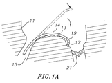
- the present disclosure provides a catheter 10 having a tip assembly 17 for mapping and/or ablation at its distal end.
- the catheter comprises an elongated catheter body 12 having proximal and distal ends, a deflectable intermediate section 14 at the distal end of the catheter body 12, and a control handle 16 at the proximal end of the catheter body.
- the tip assembly 17 is connected to the deflectable intermediate section 14 by a flexible section 19 which enables the tip assembly 17 to extend from the intermediate section 14 either in plane with or at a preset off-axis angle and/or off-plane angle.
- the tip assembly 17 is adapted for ablation although it is understood by one of ordinary skill in the art that the tip assembly may be adapted for mapping applications, as well.
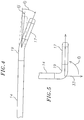
- the catheter 10 is adapted for use in a right heart 11 to map or ablate a region with a generally convex contour such as an inferior vena cava-tricuspid isthmus 13.
- this region is accessible to the catheter 10 despite the catheter's entry to the atrium from an inferior vena cava 15 and the catheter's forward approach to the isthmus treatment site.
- the intermediate section 14 is deflected so the tip assembly can reach the isthmus despite the generally convex curvature of the isthmus. The deflection also enables the intermediate section to approximate and assume the convex curvature such that motion of the heart.is transferred to catheter to stabilize the catheter.
- the tip assembly 17 and tissue surface of the isthmus 13 are enabled by an in-plane canting of the tip assembly in the direction of the deflection.
- the highly flexible section 19 connecting the tip assembly 17 and the intermediate section 14 not only enables the in-plane extension of the tip assembly but it also allows the tip assembly to maintain contact with the tissue surface despite the uneven and nonuniform surface of the isthmus 13 that spans between a tricuspid valve 21 and the inferior vena cava IS which has recesses and protrusions that are encountered by the tip assembly 17 as it is dragged along to map and/or ablate the isthmus.
- the flexible section 19 is preshaped with a configuration that attaches the tip assembly 17 of this embodiment at a predetermined off-axis angle relative to the intermediate section 14 in a direction of the deflection of the intermediate section. Moreover, the flexible section 19 has a bending modulus greater than that of the intermediate section 14 so the tip assembly 17 can flex and adjust to the contour of the isthmus tissue surface independently of the intermediate section 14. As shown in FIG. 1A , the off-axis extension of the tip assembly 17 from the intermediate section 14 enables contact between the tip assembly 17 and tissue surface of the isthmus. The ability of the tip assembly to flex and adjust permits the tip assembly 17 to contact tissue in recessed areas without exerting excess contact pressure in elevated areas reducing the risk of perforation.
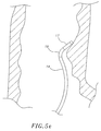
- the catheter design is adapted for ablation of cavitary or tubular structures according to the method of introduction into the body as illustrated in FIGS. 5d and 5e although it is understood by one of ordinary skill in the art that the tip assembly may be adapted for mapping applications, as well.
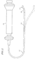
- the present disclosure also provides a catheter 10 having a tip assembly 17 for mapping and/or ablation at its distal end.
- the catheter comprises an elongated catheter body 12 having proximal and distal ends, a deflectable intermediate section 14 at the distal end of the catheter body 12, and a control handle 16 at the proximal end of the catheter body.
- the tip assembly 17 is connected to the deflectable intermediate section 14 by a flexible section 19 which enables the tip assembly 17 to extend from the intermediate section 14 either in plane with or at a preset off-axis angle and/or off-plane angle.
- the tip assembly 17 is adapted for ablation of cavitary or tubular structures according to the method of introduction into the body, although it is understood by one of ordinary skill in the art that the tip assembly may be adapted for mapping applications, aswell.
- the catheter body 12 comprises an elongated tubular construction having a single, axial or central lumen 18.
- the catheter body 12 is flexible, i.e., bendable, but substantially non-compressible along its length.
- the catheter body 12 can be of any suitable construction and made of any suitable material.
- a presently preferred construction comprises an outer wall 20 made of polyurethane or PEBAX.
- the outer wall 20 comprises an embedded braided mesh of stainless steel or the like to increase torsional stiffness of the catheter body 12 so that, when the control handle 16 is rotated, the intermediate section 14 of the catheter 10 is able to rotate in a corresponding manner.
- the outer diameter of the catheter body 12 is not critical, but is preferably no more than about 9 french, more preferably about 7 french.
- the thickness of the outer wall 20 is not critical, but is thin enough so that the central lumen 18 can accommodate a puller wire, one or more lead wires, and any other desired wires, cables or tubes.
- the inner surface of the outer wall 20 is lined with a stiffening tube 21 to provide improved torsional stability.
- a particularly preferred catheter 10 has an outer wall 20 with an outer diameter of from about 0.090 inches to about 0.094 inches and an inner diameter of from about 0.061 inches to about 0.065 inches.
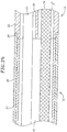
- the intermediate section 14 comprises a short section of tubing 22 having multiple lumens, is shown in FIG. 3a .
- a first lumen 30 carries one or more lead wires 50 and any other components (e.g., thermocouple wires 53 and 54 for monitoring tissue temperature) extending along the catheter ( FIGS. 2a , and 3 ).
- a second lumen 32 carries a puller wire 64 ( FIG. 3 ).
- a third lumen 34 carries an electromagnetic sensor cable 74, and a fourth lumen 35 carries an irrigation tube 61 for supplying fluid to the tip assembly 17.
- the tubing 22 is made of a suitable non-toxic material that is preferably more flexible than the catheter body 12.
- a presently preferred material for the tubing 22 is braided polyurethane, i.e., polyurethane with an embedded mesh of braided stainless steel or the like.
- the number of lumens or the size of each lumen is not critical, but is sufficient to house the lead wires, puller wire, electromagnetic sensor cable, thermal sensors and/or irrigation tube(s) depending on the circumstances.
- the useful length of the catheter 10, i.e., that portion that can be inserted into the body excluding the tip assembly 17, can vary as desired. Preferably the useful length ranges from about 110cm to about 120cm.
- the length of the intermediate section 14 is a relatively small portion of the useful length, and preferably ranges from about 3.5c m to about 10cm, more preferably from about 5cm to about 6.5cm.
- FIGs. 2a and 2b A preferred means for attaching the catheter body 12 and the intermediate section 14 is illustrated in FIGs. 2a and 2b .
- the proximal end of the intermediate section 14 comprises an outer circumferential notch 26 that receives the inner surface of the outer wall20 of the catheter body 12.
- the intermediate section 14 and catheter body 12 are attached by glue or the like.
- a spacer (not shown) can he located within the catheter body between the distal end of the stiffening tube 21 and the proximal end of the intermediate section 14.
- the spacer provides a transition in flexibility at the junction of the catheter body 12 and intermediate section 14, which allows the junction to bend smoothly without folding or kinking.
- a catheter having such a spacer is described in U.S. Patent No. 5,964,757 ..
- the puller wire 64 is provided for deflection of the intermediate section 14 (see FIG. 1A ).
- the puller wire 64 extends through the catheter body 12. Its proximal end is anchored to the control handle 16, and its distal end is anchored to the distal end of the intermediate section 14 in the lumen 32 by any suitable means, for example, adhesives forming glue joint 27 ( FIG. 3 ).
- the puller wire 64 is made of any suitable metal, such as stainless steel or Nitinol, and is preferably coated with Teflon® or the like. The coating imparts lubricity to the puller wire 64.
- the puller wire 64 preferably has a diameter ranging from about 0.006 to about 0.010 inch.
- a compression coil 66 is situated within the catheter body 12 in surrounding relation to the puller wire 64, as shown in FIG. 2a , the compression coil 66 extends from the proximal end of the catheter body 12 to the proximal end of the intermediate section 14.
- the compression coil 66 is made of any suitable metal, preferably stainless steel.
- the compression coil 66 is tightly wound on itself to provide flexibility, i.e., bending, but to resist compression.
- the inner diameter of the compression coil 66 is preferably slightly larger than the diameter of the puller wire 64.
- the Teflon® coating on the puller wire 64 allows it to slide freely within the compression coil 66.
- the outer surface of the compression coil 66 is covered by a flexible, non-conductive sheath 68, e.g., made of polyimide tubing.
- the compression coil 66 is anchored to the outer wall of the catheter body 12 by proximal glue joint 70 and at its distal end to the intermediate section 14 by distal glue joint 71.
- Both glue joints 70 and 71 preferably comprise polyurethane glue or the like.
- the glue may be applied by means of a syringe or the like through a hole made between the outer surface of the catheter body 12 and the central lumen 18. Such a hole may be formed, for example, by a needle or the like that punctures the outer wall 20 of the catheter body 12 which is heated sufficiently to form a permanent hole.
- the glue is then introduced through the hole to the outer surface of the compression coil 66 and wicks around the outer circumference to form a glue joint about the entire circumference of the compression coil.
- deflection of the intermediate section 14 by longitudinal movement of the puller wire 64 allows the intermediate section 14 to generally approximate and conform to the convex curvature of the isthmus.
- the deflected intermediate section 14 can sit on the isthmus and transmit the motion of the heart during systole, diastole and respiration to the entire catheter.
- the distal tip of the catheter is thus both stable and moves in synchrony with the heart.
- the tip assembly 17 is attached to the intermediate section 14 by the pre-shaped flexible section 19.
- the flexible section 19 supports the tip assembly 17 at an in-plane off-axis angle from the distal end of the intermediate section 14.
- the angle ⁇ may range between about 0 degrees to about 90 degrees, preferably between about 10 degrees to 60 degrees, and more preferably about 30 degrees.
- the angle ⁇ effectively increases the deflection angle to enable the tip assembly 17 to reach further around the isthmus and contact the tissue surface.
- the flexibility of the section 19 allows the angle ⁇ to be varied from the initially set angle to zero degree (or on-axis position) with minimal force applied to the tip assembly 17 through contact with the tissue.
- the flexible section 19 is constructed with sufficient shape memory and/or sufficient flexibility and elasticity so that the tip assembly 17 can temporarily assume a different (greater or lesser) angle ⁇ as needed for the tip assembly to pivot at its proximal end.
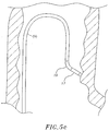
- the flexible section 19 can be sufficiently soft to allow the tip assembly 17 to be displaced from its preset off-axis angle ⁇ to an on-axis angle where ⁇ is about zero, and sufficiently elastic to return (or at least bias the return of) the tip assembly 17 to its preset off-axis angle ⁇ thereafter, whether the displacement was caused by a formation 37 in the tissue surface, the tip assembly being caught or buried in the surrounding tissue, or a "steam pop" where a build up of pressure dislodges the tip assembly from tissue contact.
- the flexible section 19 has a relatively high flexural modulus measuring on a Durometer scale no greater than about 25D to 35D and/or no greater than about 1/2 to 1/4 of the Durometer measurement of the intermediate section 14.
- the flexible section 19 acts as a "shock absorber" when the tip assembly is jarred or otherwise displaced from its preset position.
- the flexible section 19 enables the tip assembly 17 to pivot away from the recess 37 independently of the intermediate section 14 so that the tip assembly can remain in contact with the tissue.
- the tip assembly 17 can move from its preset angle 0 (solid lines) to a displaced position at angle 0' (broken lines) without significantly displacing the intermediate section 14 whether or not deflected.
- the shape memory of the material 45 of the flexible section 19 also allows the catheter to be advanced atraumatically in the patient's body in a generally straight configuration through a vein or artery and yet be able to assume its preformed shape when it reaches the heart.
- the highly flexible section 19 is configured to support the tip assembly 17 off-plane from the intermediate section 14 at a variety of radial angles.
- the catheter 10 is adapted to map and/or ablate another region in the right atrium with a generally convex contour, such as the Bundle of His region 43 (or "His region” hereinafter), although the His region may pose a further challenge as the region is also slightly canted anteriorly from the inferior vena cava 15.
- the His region 43 is accessible to the catheter 10 despite the catheter's entry to the atrium from the inferior vena cava 15 and the catheter's forward approach to the His region.
- the intermediate section 14 is deflected so the tip assembly 17 can reach the His region. Where the deflected intermediate section 14 can approximate and assume a convex curvature near the His region, motion of the heart is transferred to catheter to stabilize the catheter.
- contact between the tip assembly 17 and tissue surface of the His region 43 is enabled by an off-plane extension of the tip assembly 17 (which may or may not also extend at an off-axis angle from the intermediate section 14 ).
- the highly flexible section 19 between the tip assembly 17 and the intermediate section 14 allows the tip assembly to maintain contact with the His tissue surface despite the uneven and nonuniform surface of the His region which has recesses and protrusions that are encountered by the tip assembly 17 as it is dragged along to map and/or ablate the His region.
- the angle ⁇ may range between about 0 to 180 degrees, preferably about 20 to 90 degrees, and more preferably about 45 degrees as shown in the embodiment of Fig. 5 (compared with the embodiment of FIG. 4a where the angle ⁇ is about zero degrees).
- the off-plane radial angle ⁇ of the tip assembly 17 extending from the deflected intermediate section 14 allows the tip assembly to reach in an angle generally lateral of the deflection direction. As such, the His region is readily accessed by the tip assembly 17 for mapping and/or ablation.
- the off axis angle 0 and the off-plane angle ⁇ may be preset independently of one another. That is, the catheter 10 of the present invention may have the tip assembly 17 extend from the intermediate section 14 at any combination of the angle 0 and the angle ⁇ in accordance with their respective ranges set forth above, as desired or appropriate. In one embodiment of the catheter 10 for use in ablating and/or mapping the His region, the angle 0 is about 20 degrees and the angle ⁇ is about 90 degrees.
- the flexible section 19 allows the tip assembly to be displaced without displacing the intermediate section 14.
- the tip assembly 17 can be displaced from its off-plane angle under a force or weight of merely about 0.25 to about 2.0oz, and more preferably about 1.0 ounce.
- the flexible section 19 provides sufficient flexibility to reduce the risk of injury that can result from the tip assembly 17 inadvertently perforating tissue or being buried in the tissue and overheating.
- the force required to displace or capable of displacing the tip assembly from the preset angle(s) also depends on the point of application of the force to the tip assembly, as well as the length of the tip assembly.
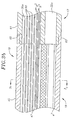
- the flexible section 19 comprises a short section of material 45 (e.g., tubing) with a central lumen 47 through which the lead wire(s) 50, thermocouple wires 53 and 54, sensor cable 74 and irrigation tube 61 extend distally and connect to the tip assembly 17.
- a junction 25 of the intermediate section 14 and the flexible section 19 is shown in FIG. 3 .
- the proximal end of the material 45 of the tip assembly 17 comprises an outer circumferential notch 49 that receives the inner surface of the tubing 22 of the intermediate section 14.
- the intermediate section 14 and the flexible section 19 are attached by glue or the like.
- the flexible section can be made of polyurethane, PEBAX, silicone or combinations thereof and is preformed (used generally interchangeably with "preshaped” herein) with shape memory by placing the tubing 45 in a delrin mold and heating the mold at about 100°C for about 30 minutes.
- the tip assembly and the flexible section may be formed as a single unit with the flexibility of the tip assembly or flexible section determined by the incorporated sensors, wires and electrodes.
- the length of the flexible section 19 can vary as desired and can range between about 0.1cm and 2.0cm, preferably between about 0.2cm and 1.0cm, and more preferably about 5.0cm.
- lateral stability can be provided in the tip assembly 17 with the use of struts or ribbons 51 provided in walls of the material 45 of the flexible section 19, as shown in FIG. 3c , or elsewhere on or in the tubing as desirable.
- a pair of struts 51 can be aligned along any diameter of the material 45 to stabilize the tip assembly. In the embodiment of Fig. 3c , the struts minimize lateral movement along direction X but still allow displacement along direction Y.
- the intermediate section 14 may have a length ranging between about 1.0cm and 20cm, preferably between about 4.0c m and 16cm, and more preferably between about 7.0cm and 12cm.
- the intermediate section 14 may assume a "J" curve when deflected for flutter treatment and procedures and a "D" curve for HIS treatment and procedures.
- the intermediate section and its deflection curvature may assume a variety of sizes and shapes as desirable or appropriate for the intended region of ablation or mapping.
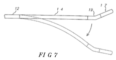
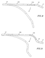
- the flexible section 19 may flexibly extend the tip assembly 17 in a direction generally opposite to the direction of deflection of the intermediate section 14 ( Fig. 7 ), or that the intermediate section may be divided into distal and proximal sections 14a and 14b with the proximal intermediate section 14b deflectable and the distal intermediate section 14a with shape-memory configured generally straight ( FIG. 8 ) or with a curve ( FIG. 9 ), as desirable or appropriate for the intended region of ablation or mapping.
- the tip assembly 17 comprises a short section of material tubing 61 (e.g., tubing) ( FIGs . 3b , 5 A and 5 b) comprising four lumens 30a, 32a, 34a and 35A, generally corresponding to and aligned with the four lumens 30, 32, 34 and 35 respectively, of the intermediate section 14.
- the length of the tip assembly 17 can be varied as desired, but preferably ranges between about 8mm to about 15mm, and more preferably is about 10mm.
- Ajunction 63 of the flexible section 19 and the tip assembly 17 is shown in FIG. 3B .
- the proximal end of the material 61 of the tip assembly 17 comprises an outer circumferential notch 65 that receives the inner surface of the tubing 45 of the flexible section 19.
- the flexible section 19 and tip assembly 17 are attached by glue or the like.
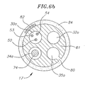
- FIG. 6a illustrates the tip assembly 17 configured as an ablation assembly.
- a coil electrode 82 is coiled around the length of the ablation assembly 17.
- the longitudinal span of the coil electrode 82 may be made of any suitable metal, preferably platinum/iridium and ranges in length from about 6 to about 10mm, preferably about 8mm to generally match the length of the ablation assembly 17.
- the ablation assembly 17 is irrigated and comprises a plurality of irrigation ports 80 disposed along most of the length of the ablation assembly 17 through which fluid can pass to the outer surface of the ablation assembly to cool the ablation site.
- the coil and the irrigation ports 80 are arranged so that an irrigation port lies between each wind of the coil electrode 82.
- the irrigation ports may comprise round holes formed on the surface of the tubing 61 on the side of the ablation assembly 17 in communication with the fourth lumen 35A which is supplied fluid by the irrigation tube 61 whose distal end is slightly proximal of the most proximal irrigation port. Any number of irrigation ports 80 may be used.
- the tubing 61 of the ablation assembly 17 is configured with about 10 irrigation ports 80.
- a porous protective covering 84 of, for example, expanded polytetrafluoroethylene (EPTFE), is disposed over the tubing 61in surrounding relation to and covering the coil electrode 82 and irrigation ports 80
- a tip electrode lead wire 50 ( FIG. 6b ) connects the coil electrode 82 to a suitable source of ablation energy (not shown), preferably radio frequency (RF) energy.
- the distal end of the lead wire 50 is attached to the proximal end of the coil electrode 82.
- the proximal end of the lead wire 50 is electrically connected to the source of ablation energy as is known in the art.
- the lead wire 50 extends through the first lumen 30a of the ablation assembly 17, the central lumen 47 of the flexible section 19, the first lumen 30 of the intermediate section 14, the central lumen 18 of the catheter body 12, and the control handle 16, and terminates at its proximal end in a connector (not shown).
- mapping and/or ablation ring electrodes 83a and 83h maybe mounted on the ablation assembly 17. Additional ring electrodes may be contained within the ablation assembly or the intermediate section depending on spacing or the application of the catheter.
- the ring electrodes 83a and 83h can be mounted over the coil electrode 82 and underneath the porous covering 84. In the illustrated example, the first ring electrode 83a is positioned in between the two distal most irrigation ports 80. The second ring electrode 83h is positioned in between the two proximal most irrigation ports 80.
- the ring electrodes 83a and 83b are mounted to the coil electrode 82 by any suitable means, for example by welding, soldering or the like.
- the ring electrodes 83a and 83b are electrically connected to the coil electrode 82 and its associated lead wire for ablation purposes.
- the ring electrodes 83a and 83b serve in part to hold the coil electrode 82 in place on the tubing 61 of the ablation assembly.
- the ring electrodes 83a and 83b also serve to flatten the coil electrode 82 on the surface of the tubing 61, thereby preventing any rough edges of the coil electrode 82 from cutting into the porous covering 84.
- thermocouples any conventional temperature sensors, e.g. thermocouples or thermistors, may be used.
- the temperature sensors comprise two thermocouples formed by two enameled wire pairs.
- One wire of each wire pair is a copper wire 53, e.g., a number "40" copper wire.
- the other wire of each wire pair is a constantan wire 54.
- the wires 53 and 54 of each wire pair are electrically isolated from each other except at their distal ends where they are twisted together, covered with a short piece of plastic tubing 55 ( FIG. 6a ), e.g., polyimide, and covered with epoxy.
- the wires 53 and 54 of each wire pair extend out a hole in the side wall of the tubing 61 and are anchored to the outer surface of tubing 61.
- the hole in the side wall of the distal region is sealed by a plug. Any suitable seal may be used, for example glue or the like.
- Each plastic tubing 55 is mounted on the outer surface of the tubing 61 by polyurethane glue or the like.
- One of the two thermocouples is anchored immediately distal the distal most irrigation port 80, as shown in FIG. 6a .
- the second of the two thermocouples is anchored immediately proximal the proximal most irrigation port 80.
- the wires 53 and 54 extend through the first lumen 30 in the ablation assembly 17 and intermediate section 14, through the central lumen 18 of the catheter body 12 and out through the control handle 16 to a connector (not shown) connectable to a temperature monitor (not shown).
- mapping and/or ablation ring electrodes can be mounted on the tubing 45 of the flexible section 19 and tubing 61 of the ablation assembly 17, as shown in FIGs. 5 and 6a . These ring electrodes might be desirable, for example, for mapping the region to be ablated before ablation begins or after ablation to assure that the lesions blocked the electrical activity as desired.
- a ring electrode 85A can be mounted on the proximal end of the tubing 61 of the ablation assembly 17 over the porous covering 84 so that the proximal end of the porous covering 84 can be tucked underneath the ring electrode 85A to lock the proximal position of the porous covering 84.
- a second ring electrode 85b can be mounted on the distal end of the tubing 61 so that the distal end of the porous covering 84 can be tucked underneath the ring electrode 85b to lock the distal position of the porous covering 84.
- the tip assembly 17 whether adapted for mapping or ablation may be constructed with or without irrigation, with or without temperature sensors, using suitable ring electrodes for sensing and/or ablation, as understood by one of ordinary skill in the art.
- the relationship between the tip assembly and the flexible section remains generally as described herein.
- two additional ring electrodes 86a and 86b for mapping are mounted on the flexible section 19.
- the first ring electrode 86a is positioned approximately 5 mm proximal the proximal locking ring electrode 85A and is used to confirm the position of the ablation assembly in the atrium.
- the second ring electrode 86b is positioned approximately 2.5 mm proximal the first ring electrode 86a and is also used to confirm the position of the ablation assembly in the atrium.
- the mapping electrodes may be mounted at different locations on the ablation assembly 17, flexible section 19 and/or intermediate section 14 as desired.
- each ring electrode 85A, 85b, 86a, 86b and 86c is connected to a corresponding lead wire 50.
- the distal end of each lead wire 50 is attached to the corresponding ring electrode.
- the proximal end of each lead wire 50 is electrically connected to a suitable monitoring device for monitoring electrical activity.
- Each lead wire 50 extends through the first lumen 30a of the ablation assembly 17, the central lumen 47 of the tubing 45, the first lumen 30 of the intermediate section 14, the central lumen 18 of the catheter body 12, and the control handle 16, and terminates at 'its proximal end in a connector (not shown).
- each lead wire 50 extending through the control handle 16, the central lumen 18 of the catheter body 12, and at least the proximal section of the intermediate section 14 is enclosed within a protective sheath 62 to prevent contact with other lead wires or other components of the catheter.
- the protective sheath 62 can be made of any suitable material, preferably polyimide.
- the protective sheath 62 is anchored at its distal end to the proximal end of the intermediate section 14 by gluing it in the first lumen 30 with polyurethane glue or the like. As would be recognized by one skilled in the art, the protective sheath 62 can be eliminated if desired.
- an electromagnetic navigation sensor 72 may be contained within the ablation assembly 17.
- the electromagnetic sensor 72 is preferably situated at the distal tip of the ablation assembly 17 and is approximately 5mm long.
- the electromagnetic sensor 72 is positioned in the third lumen 34a of the ablation assembly 17.
- the electromagnetic sensor 72 is mounted to the tubing 61 of the ablation assembly 17 by any suitable means, e.g. by polyurethane glue or the like.
- the electromagnetic sensor 72 is connected to an electromagnetic sensor cable 74, which extends through the third lumen 34a in the ablation assembly 17, the central lumen 47 of the flexible section 19, the third lumen 34 of the intermediate section 14, through the catheter body 12, and out through the control handle 16.
- the electromagnetic sensor cable 74 comprises multiple wires encased within a plastic covered sheath.
- the sensor cable 74 is connected to a circuit board (not shown).
- the circuit board amplifies the signal received from the electromagnetic sensor 72 and transmits it to a computer in a form understandable by the computer. Because the catheter is designed for a single use only, the circuit board may contain an EPROM chip which shuts down the circuit board approximately 24 hours after the catheter has been used. This prevents the catheter, or at least the electromagnetic sensor from being used twice.
- Suitable electromagnetic sensors for use with the present invention are described, for example, in U.S. Patent Nos. 5,558,091 , 5,443,489 , 5,480,422 , 5,546,951 , and 5,391,199 .
- a preferred electromagnetic sensor 72 has a length of from about 6 mm to about 7 mm, preferably about 5 mm, and a diameter of about 1.3 mm.
- the irrigation tube 61 may be made of any suitable material, and is preferably made of polyimide tubing.
- a preferred irrigation tube has an outer diameter of from about 0.032 inch to about 0.036 inch, and an inner diameter of from about 0.028 inch to about 0.032 inch.
- the irrigation tube 61 extends through the central lumen 18 of the catheter body 12 ( FIG. 2b ), the fourth lumen 35 of the intermediate section 14, the central lumen 47 of the flexible section 19, and the fourth lumen 35A of the ablation assembly 17 ( FIG. 3a ), and terminates slight proximal of the most proximal irrigation port 80 in the ablation assembly 17.
- the proximal end of the irrigation tube 61 extends through the control handle 16 and terminates in a luer hub or the like (not shown). Fluid is introduced into the irrigation tube 61 through the luer hub. The fluid, e.g. saline, is then introduced to the fourth lumen 35A of the ablation assembly 17 by the irrigation tube 61 and passes to the outer surface of the tubing 61 through the irrigation ports 80 ( FIG. 5A ). The fluid is then dispersed over generally the entire surface of the ablation assembly 17 by the porous covering 84. This irrigation enables creation of deeper lesions.
- the fluid e.g. saline
- the catheter 10 is inserted into the patient through a suitable guiding sheath whose distal end is positioned at a desired mapping or ablating location.
- a suitable guiding sheath for use in connection with the present invention is the PrefaceTM Braided Guiding Sheath, commercially available from Biosense Webster, Inc. (Diamond Bar, California).
- the distal end of the sheath is guided into one of the atria.
- a catheter in accordance with the present invention is fed through the guiding sheath until its distal end extends out of the distal end of the guiding sheath.
- the tip assembly 17, the flexible section 19 and the intermediate section 14 are generally straightened to fit through the sheath.
- the guiding sheath is pulled proximally, allowing the deflectable intermediate section 14, the flexible section 19 and the tip assembly 17 to extend outside the sheath, and return to their original preformed shapes with the tip assembly 17 extending from the intermediate section 14 at a predetermined off-axis angle ⁇ and/or off-plane angle ⁇ .
- the intermediate section 14 is deflected to approximate the generally convex curvature of the cava-tricuspid isthmus or the His region where the intermediate section 14 can rest on the tissue and is stabilized and in synch with the motion of the heart.
- the tip assembly 17 With the intermediate section 14 deflected, the tip assembly 17 makes contact with tissue in the region by means of the preset off-plane angle(s) provided by the flexible section 19.
- the ablation assembly is positioned and the flexible section 19 allows the ablation assembly to be readily displaced from contact with the tissue before damage can occur from perforation, steam build-up and the like.
- the tip assembly 17 is dragged along the tissue surface.
- the flexible section 19 flexes as the ablation assembly 17 pivots from the preset angle(s) to absorb the movement without affecting the intermediate section 14.
- the catheter body may also be rotated to form a linear line of block at the His region. Because the off-plane angle allows the ablation assembly to reach tissue lateral of the plane of deflection, rotation of the ablation assembly (e.g., by rotation of the catheter body and/or the control handle) can create a generally linear ablation line.
- the tip assembly 17 maintains continuous contact with the tissue for improved lesions.
- similar manipulations of the catheter and the control handle enable the mapping electrodes 85A, 85b, 86a, 86b and 86c to map in a linear or circumferential pattern.
Landscapes
- Health & Medical Sciences (AREA)
- Life Sciences & Earth Sciences (AREA)
- Engineering & Computer Science (AREA)
- Veterinary Medicine (AREA)
- Animal Behavior & Ethology (AREA)
- Public Health (AREA)
- Biomedical Technology (AREA)
- Heart & Thoracic Surgery (AREA)
- General Health & Medical Sciences (AREA)
- Surgery (AREA)
- Pulmonology (AREA)
- Anesthesiology (AREA)
- Biophysics (AREA)
- Hematology (AREA)
- Mechanical Engineering (AREA)
- Physics & Mathematics (AREA)
- Plasma & Fusion (AREA)
- Nuclear Medicine, Radiotherapy & Molecular Imaging (AREA)
- Otolaryngology (AREA)
- Cardiology (AREA)
- Medical Informatics (AREA)
- Molecular Biology (AREA)
- Surgical Instruments (AREA)
- Media Introduction/Drainage Providing Device (AREA)
- Electrotherapy Devices (AREA)
Claims (31)
- Katheter, umfassend:einen langgestreckten flexiblen schlauchförmigen Kathetherkörper (12) mit proximalen und distalen Enden;einen Zwischenabschnitt (14), der an dem distalen Ende des Katheterkörpers befestigt ist, wobei der Zwischenabschnitt in einer ersten Ebene ablenkbar ist, um sich einer allgemein konvexen Herzregion anzunähern;eine Spitzenanordnung (17); undeinen flexiblen Abschnitt (19), der die Spitzenanordnung mit dem Zwischenabschnitt in einem voreingestellten Winkel außerhalb der Ebene verbindet, so dass sich die Spitzenanordnung in eine zweite Ebene erstreckt, die sich von der ersten Ebene unterscheidet, wobei der flexible Abschnitt ausgelegt ist, eine Verschiebung der Spitzenanordnung von dem voreingestellten Winkel ohne Verschiebung des Zwischenabschnitts zu gestatten;einen Zugdraht (64) mit proximalen und distalen Enden, die sich durch den Katheterkörper erstrecken, wobei das distale Ende des Zugdrahts fest in einem distalen Ende des Zwischenabschnitts befestigt ist;einen Steuergriff (16), der mit den proximalen Enden des Katheterkörpers und des Zugdrahts verbunden ist, um den Zugdraht längs relativ zum Katheterkörper zu bewegen, wobei die Längsbewegung des Zugdrahts relativ zum Katheterkörper zur Ablenkung des Zwischenabschnitts führt;wobei der Zwischenabschnitt flexibler als der Katheterkörper ist und der flexible Abschnitt flexibler als der Zwischenabschnitt ist; unddie Durometer-Messung des flexiblen Abschnitts nicht größer als ungefähr ½ bis ¼ der Durometer-Messung des Zwischenabschnitts ist.
- Katheter nach Anspruch 1, wobei der Zwischenabschnitt einen distalen Abschnitt (14a) und einen proximalen Abschnitt (14b) umfasst, wobei der distale Abschnitt Formgedächtnis aufweist.
- Katheter nach Anspruch 2, wobei der distale Abschnitt (14a) gebogen ist.
- Katheter nach Anspruch 2, wobei der proximale Abschnitt (14b) ablenkbar ist.
- Katheter nach Anspruch 1, wobei der flexible Abschnitt die Spitzenanordnung (17) mit dem Zwischenabschnitt (14) in einem voreingestellten außeraxialen Winkel verbindet.
- Katheter nach Anspruch 1, wobei der flexible Abschnitt wenigstens eine Stützstruktur (51) zur Minimierung der Bewegung der Spitzenanordnung (17) in einer gewählten Richtung umfasst.
- Katheter nach Anspruch 5, wobei der außeraxiale Winkel in einer Ablenkungsrichtung des Zwischenabschnitts (14) liegt.
- Katheter nach Anspruch 5, wobei der außeraxiale Winkel im Bereich zwischen ungefähr 2 und 180 Grad allgemein in einer Ablenkungsrichtung des Zwischenabschnitts (14) liegt.
- Katheter nach Anspruch 5, wobei der außeraxiale Winkel im Bereich zwischen ungefähr 2 und 180 Grad allgemein entgegengesetzt zu einer Ablenkungsrichtung des Zwischenabschnitts (14) liegt.
- Katheter nach Anspruch 1, wobei der außeraxiale Winkel im Bereich zwischen ungefähr 2 und 180 Grad allgemein in einer Ablenkungsrichtung des Zwischenabschnitts (14) liegt.
- Katheter nach Anspruch 1, wobei der außeraxiale Winkel im Bereich zwischen ungefähr 2 und 180 Grad allgemein entgegengesetzt zu einer Ablenkungsrichtung des Zwischenabschnitts (14) liegt.
- Katheter nach Anspruch 5, wobei die Verschiebung der Spitzenanordnung (17) zwischen der voreingestellten außeraxialen Position und einer auf der Achse liegenden Position erfolgt.
- Katheter nach Anspruch 1, wobei die Spitzenanordnung (17) für Mapping ausgelegt ist.
- Katheter nach Anspruch 1, wobei die Spitzenanordnung (17) für Ablation ausgelegt ist.
- Katheter nach Anspruch 1, der ausgelegt ist, die Spitzenanordnung (17) während der Bewegung des Katheters mit dem Gewebe in Kontakt zu halten, ohne den Zwischenabschnitt (14) zu beeinträchtigen.
- Katheter nach Anspruch 15, wobei ein abgelenkter Zwischenabschnitt (14) sich allgemein an eine Region des cavotricuspidalen Isthmus im rechten Vorhof, eine His-Region im rechten Vorhof, eine Region eines rechten Vorhofs, eine Region eines linken Vorhofs oder eine Vena cava superior anpasst.
- Katheter nach Anspruch 15, wobei Kontakt zwischen dem Zwischenabschnitt (14) und der allgemein konvexen Region den Zwischenabschnitt zur Herzbewegung während Systole, Diastole oder Atmung synchronisiert.
- Katheter nach Anspruch 15, wobei Kontakt zwischen dem Zwischenabschnitt (14) und der allgemein konvexen Region die Spitzenanordnung (17) allgemein stabilisiert.
- Katheter nach Anspruch 15, wobei die Spitzenanordnung eine Ablationselektrode aufweist.
- Katheter nach Anspruch 15, wobei die Spitzenanordnung eine Mapping-Elektrode aufweist.
- Katheter nach Anspruch 1, wobei die Spitzenanordnung (17) eine Ablationsanordnung umfasst.
- Katheter nach Anspruch 21, wobei die Ablationsanordnung das Folgende umfasst:eine Vielzahl von Irrigationsöffnungen (80);eine Spulenelektrode (82); undeine poröse Abdeckung (84) in umgebender Beziehung zur Spulenelektrode und den Irrigationsöffnungen.
- Katheter nach Anspruch 21, wobei die Spulenelektrode (82) eine Länge im Bereich von ungefähr 8 mm bis ungefähr 15 mm aufweist.
- Katheter nach Anspruch 23, wobei die Spulenelektrode (82) eine Länge von ungefähr 10 mm aufweist.
- Katheter nach Anspruch 22, wobei die poröse Abdeckung (84) expandiertes Polytetrafluorethylen umfasst.
- Katheter nach Anspruch 21, ferner umfassend einen Temperatursensor, der in der Ablationsanordnung angebracht ist.
- Katheter nach Anspruch 22, ferner umfassend:eine proximale arretierende Ringelektrode (85A), die auf einer proximalen Region der Ablationsanordnung über der Spulenelektrode und der porösen Abdeckung angebracht ist; undeine distale arretierende Ringelektrode, die auf einer distalen Region der Ablationsanordnung über der Spulenelektrode und der porösen Abdeckung angebracht ist.
- Katheter nach Anspruch 21, ferner umfassend eine oder mehrere Ringelektroden proximal von der Ablationsanordnung.
- Katheter nach Anspruch 21, ferner umfassend einen elektromagnetischen Sensor (72), der in der Ablationsanordnung angebracht ist.
- Katheter nach Anspruch 21, wobei der Zwischenabschnitt (14) ferner ein Stützelement umfasst, das ein Material mit Formgedächtnis umfasst, um die vorgeformte Kurve bereitzustellen.
- Katheter nach Anspruch 21, ferner umfassend einen Irrigationsschlauch (61), der sich in die Ablationsanordnung erstreckt.
Applications Claiming Priority (2)
| Application Number | Priority Date | Filing Date | Title |
|---|---|---|---|
| US11/323,908 US20070156114A1 (en) | 2005-12-29 | 2005-12-29 | Deflectable catheter with a flexibly attached tip section |
| PCT/US2006/062215 WO2007076312A2 (en) | 2005-12-29 | 2006-12-18 | Deflectable catheter with a flexibly attached tip section |
Publications (3)
| Publication Number | Publication Date |
|---|---|
| EP1968679A2 EP1968679A2 (de) | 2008-09-17 |
| EP1968679A4 EP1968679A4 (de) | 2013-01-23 |
| EP1968679B1 true EP1968679B1 (de) | 2016-09-21 |
Family
ID=38218783
Family Applications (1)
| Application Number | Title | Priority Date | Filing Date |
|---|---|---|---|
| EP06840297.3A Not-in-force EP1968679B1 (de) | 2005-12-29 | 2006-12-18 | Ablenkbarer katheter mit flexibel befestigtem spitzenabschnitt |
Country Status (8)
| Country | Link |
|---|---|
| US (3) | US20070156114A1 (de) |
| EP (1) | EP1968679B1 (de) |
| JP (1) | JP2009522020A (de) |
| CN (1) | CN101528145B (de) |
| AU (1) | AU2006330644B2 (de) |
| CA (1) | CA2635676C (de) |
| MX (1) | MX2008008617A (de) |
| WO (1) | WO2007076312A2 (de) |
Cited By (29)
| Publication number | Priority date | Publication date | Assignee | Title |
|---|---|---|---|---|
| US11617861B2 (en) | 2014-06-17 | 2023-04-04 | St. Jude Medical, Cardiology Division, Inc. | Triple coil catheter support |
| US11622806B2 (en) | 2010-04-09 | 2023-04-11 | St Jude Medical International Holding S.À R.L. | Control handle for a contact force ablation catheter |
| US11642063B2 (en) | 2018-08-23 | 2023-05-09 | St. Jude Medical, Cardiology Division, Inc. | Curved high density electrode mapping catheter |
| US11642064B2 (en) | 2015-10-21 | 2023-05-09 | St. Jude Medical, Cardiology Division, Inc. | High density electrode mapping catheter |
| US11647935B2 (en) | 2017-07-24 | 2023-05-16 | St. Jude Medical, Cardiology Division, Inc. | Masked ring electrodes |
| US11672947B2 (en) | 2017-11-28 | 2023-06-13 | St. Jude Medical, Cardiology Division, Inc. | Lumen management catheter |
| US11696716B2 (en) | 2008-12-29 | 2023-07-11 | St. Jude Medical, Atrial Fibrillation Division, Inc. | Non-contact electrode basket catheters with irrigation |
| US11707229B2 (en) | 2015-05-08 | 2023-07-25 | St Jude Medical International Holding S.À R.L. | Integrated sensors for medical devices and method of making integrated sensors for medical devices |
| US11786705B2 (en) | 2016-10-24 | 2023-10-17 | St. Jude Medical, Cardiology Division, Inc. | Catheter insertion devices |
| US11826172B2 (en) | 2014-05-06 | 2023-11-28 | St. Jude Medical, Cardiology Division, Inc. | Electrode support structure assembly |
| US11839424B2 (en) | 2010-05-05 | 2023-12-12 | St. Jude Medical, Atrial Fibrillation Division, Inc | Monitoring, managing and/or protecting system and method for non-targeted tissue |
| US11844910B2 (en) | 2014-06-05 | 2023-12-19 | St. Jude Medical, Cardiology Division, Inc. | Deflectable catheter shaft section |
| US11896284B2 (en) | 2007-12-28 | 2024-02-13 | St. Jude Medical, Atrial Fibrillation Division, Inc | System and method for measurement of an impedance using a catheter such as an ablation catheter |
| US11918762B2 (en) | 2018-10-03 | 2024-03-05 | St. Jude Medical, Cardiology Division, Inc. | Reduced actuation force electrophysiology catheter handle |
| US12011549B2 (en) | 2017-01-19 | 2024-06-18 | St. Jude Medical, Cardiology Division, Inc. | Sheath visualization |
| US12036027B2 (en) | 2016-10-28 | 2024-07-16 | St. Jude Medical, Cardiology Division, Inc. | Flexible high-density mapping catheter |
| US12048545B2 (en) | 2014-10-27 | 2024-07-30 | St. Jude Medical, Cardiology Division, Inc. | Apparatus and method for connecting elements in medical devices |
| US12076079B2 (en) | 2016-05-03 | 2024-09-03 | St. Jude Medical, Cardiology Division, Inc. | Irrigated high density electrode catheter |
| US12082936B2 (en) | 2018-09-27 | 2024-09-10 | St. Jude Medical, Cardiology Division, Inc. | Uniform mapping balloon |
| US12121357B2 (en) | 2015-10-21 | 2024-10-22 | St. Jude Medical, Cardiology Division, Inc. | High density electrode mapping catheter |
| US12156979B2 (en) | 2018-05-21 | 2024-12-03 | St. Jude Medical, Cardiology Division, Inc. | Deflectable catheter shaft with pullwire anchor feature |
| US12263338B2 (en) | 2013-01-16 | 2025-04-01 | St. Jude Medical, Cardiology Division, Inc. | Flexible high-density mapping catheter tips and flexible ablation catheter tips with onboard high-density mapping electrodes |
| US12263014B2 (en) | 2020-08-18 | 2025-04-01 | St. Jude Medical, Cardiology Division, Inc. | High-density electrode catheters with magnetic position tracking |
| US12295649B2 (en) | 2010-12-02 | 2025-05-13 | St. Jude Medical, Atrial Fibrillation Division, Inc. | Catheter electrode assemblies and methods of construction thereof |
| US12376901B2 (en) | 2018-05-21 | 2025-08-05 | St. Jude Medical, Cardiology Division, Inc. | Radio-frequency ablation and direct current electroporation catheters |
| US12383333B2 (en) | 2015-01-28 | 2025-08-12 | St. Jude Medical, Cardiology Division, Inc. | Thermal mapping catheter |
| US12551656B2 (en) | 2017-07-07 | 2026-02-17 | St. Jude Medical, Cardiology Division, Inc. | Layered high density electrode mapping catheter |
| US12551658B2 (en) | 2022-03-25 | 2026-02-17 | St. Jude Medical, Cardiology Division, Inc. | Steerable introducer with slide block divider |
| US12575877B2 (en) | 2018-04-05 | 2026-03-17 | St. Jude Medical, Cardiology Division, Inc. | High density electrode mapping catheter |
Families Citing this family (92)
| Publication number | Priority date | Publication date | Assignee | Title |
|---|---|---|---|---|
| EP1542587B1 (de) | 2002-08-24 | 2011-04-27 | St. Jude Medical, Atrial Fibrillation Division, Inc. | Verfahren und gerät zur lokalisierung der fossa ovalis und durchführung einer transseptalen punktion |
| US8517999B2 (en) | 2007-04-04 | 2013-08-27 | St. Jude Medical, Atrial Fibrillation Division, Inc. | Irrigated catheter with improved fluid flow |
| US8764742B2 (en) | 2007-04-04 | 2014-07-01 | St. Jude Medical, Atrial Fibrillation Division, Inc. | Irrigated catheter |
| US8979837B2 (en) | 2007-04-04 | 2015-03-17 | St. Jude Medical, Atrial Fibrillation Division, Inc. | Flexible tip catheter with extended fluid lumen |
| US10220187B2 (en) | 2010-06-16 | 2019-03-05 | St. Jude Medical, Llc | Ablation catheter having flexible tip with multiple flexible electrode segments |
| US8974454B2 (en) | 2009-12-31 | 2015-03-10 | St. Jude Medical, Atrial Fibrillation Division, Inc. | Kit for non-invasive electrophysiology procedures and method of its use |
| US11395694B2 (en) | 2009-05-07 | 2022-07-26 | St. Jude Medical, Llc | Irrigated ablation catheter with multiple segmented ablation electrodes |
| US8535308B2 (en) | 2007-10-08 | 2013-09-17 | Biosense Webster (Israel), Ltd. | High-sensitivity pressure-sensing probe |
| US8357152B2 (en) | 2007-10-08 | 2013-01-22 | Biosense Webster (Israel), Ltd. | Catheter with pressure sensing |
| US8437832B2 (en) | 2008-06-06 | 2013-05-07 | Biosense Webster, Inc. | Catheter with bendable tip |
| US9101734B2 (en) * | 2008-09-09 | 2015-08-11 | Biosense Webster, Inc. | Force-sensing catheter with bonded center strut |
| US9326700B2 (en) | 2008-12-23 | 2016-05-03 | Biosense Webster (Israel) Ltd. | Catheter display showing tip angle and pressure |
| US8600472B2 (en) | 2008-12-30 | 2013-12-03 | Biosense Webster (Israel), Ltd. | Dual-purpose lasso catheter with irrigation using circumferentially arranged ring bump electrodes |
| US8475450B2 (en) * | 2008-12-30 | 2013-07-02 | Biosense Webster, Inc. | Dual-purpose lasso catheter with irrigation |
| US8808345B2 (en) | 2008-12-31 | 2014-08-19 | Medtronic Ardian Luxembourg S.A.R.L. | Handle assemblies for intravascular treatment devices and associated systems and methods |
| US8954161B2 (en) | 2012-06-01 | 2015-02-10 | Advanced Cardiac Therapeutics, Inc. | Systems and methods for radiometrically measuring temperature and detecting tissue contact prior to and during tissue ablation |
| US8926605B2 (en) | 2012-02-07 | 2015-01-06 | Advanced Cardiac Therapeutics, Inc. | Systems and methods for radiometrically measuring temperature during tissue ablation |
| US9277961B2 (en) | 2009-06-12 | 2016-03-08 | Advanced Cardiac Therapeutics, Inc. | Systems and methods of radiometrically determining a hot-spot temperature of tissue being treated |
| US9226791B2 (en) | 2012-03-12 | 2016-01-05 | Advanced Cardiac Therapeutics, Inc. | Systems for temperature-controlled ablation using radiometric feedback |
| US10688278B2 (en) | 2009-11-30 | 2020-06-23 | Biosense Webster (Israel), Ltd. | Catheter with pressure measuring tip |
| US8920415B2 (en) | 2009-12-16 | 2014-12-30 | Biosense Webster (Israel) Ltd. | Catheter with helical electrode |
| US8521462B2 (en) | 2009-12-23 | 2013-08-27 | Biosense Webster (Israel), Ltd. | Calibration system for a pressure-sensitive catheter |
| US8529476B2 (en) | 2009-12-28 | 2013-09-10 | Biosense Webster (Israel), Ltd. | Catheter with strain gauge sensor |
| US8608735B2 (en) | 2009-12-30 | 2013-12-17 | Biosense Webster (Israel) Ltd. | Catheter with arcuate end section |
| US8374670B2 (en) * | 2010-01-22 | 2013-02-12 | Biosense Webster, Inc. | Catheter having a force sensing distal tip |
| US9949791B2 (en) | 2010-04-26 | 2018-04-24 | Biosense Webster, Inc. | Irrigated catheter with internal position sensor |
| US9943362B2 (en) | 2010-04-28 | 2018-04-17 | Biosense Webster, Inc. | Irrigated ablation catheter with improved fluid flow |
| US9943363B2 (en) * | 2010-04-28 | 2018-04-17 | Biosense Webster, Inc. | Irrigated ablation catheter with improved fluid flow |
| US9510894B2 (en) | 2010-04-28 | 2016-12-06 | Biosense Webster (Israel) Ltd. | Irrigated ablation catheter having irrigation ports with reduced hydraulic resistance |
| US8798952B2 (en) | 2010-06-10 | 2014-08-05 | Biosense Webster (Israel) Ltd. | Weight-based calibration system for a pressure sensitive catheter |
| JP4940332B2 (ja) * | 2010-06-15 | 2012-05-30 | 日本ライフライン株式会社 | カテーテル |
| US8226580B2 (en) | 2010-06-30 | 2012-07-24 | Biosense Webster (Israel), Ltd. | Pressure sensing for a multi-arm catheter |
| US8380276B2 (en) | 2010-08-16 | 2013-02-19 | Biosense Webster, Inc. | Catheter with thin film pressure sensing distal tip |
| CN102429721B (zh) * | 2010-09-29 | 2015-08-26 | 心诺普医疗技术(北京)有限公司 | 一种消融系统 |
| US8731859B2 (en) | 2010-10-07 | 2014-05-20 | Biosense Webster (Israel) Ltd. | Calibration system for a force-sensing catheter |
| TWI556849B (zh) | 2010-10-21 | 2016-11-11 | 美敦力阿福盧森堡公司 | 用於腎臟神經協調的導管裝置 |
| WO2012061159A1 (en) | 2010-10-25 | 2012-05-10 | Medtronic Ardian Luxembourg S.A.R.L. | Catheter apparatuses having multi-electrode arrays for renal neuromodulation and associated systems and methods |
| US8979772B2 (en) | 2010-11-03 | 2015-03-17 | Biosense Webster (Israel), Ltd. | Zero-drift detection and correction in contact force measurements |
| US8617087B2 (en) * | 2010-12-03 | 2013-12-31 | Biosense Webster, Inc. | Control handle with rotational cam mechanism for contraction/deflection of medical device |
| US8364236B2 (en) * | 2011-04-22 | 2013-01-29 | Topera, Inc. | Flexible electrode assembly for insertion into body lumen or organ |
| US9220433B2 (en) | 2011-06-30 | 2015-12-29 | Biosense Webster (Israel), Ltd. | Catheter with variable arcuate distal section |
| US10743932B2 (en) | 2011-07-28 | 2020-08-18 | Biosense Webster (Israel) Ltd. | Integrated ablation system using catheter with multiple irrigation lumens |
| US9662169B2 (en) | 2011-07-30 | 2017-05-30 | Biosense Webster (Israel) Ltd. | Catheter with flow balancing valve |
| US9687289B2 (en) | 2012-01-04 | 2017-06-27 | Biosense Webster (Israel) Ltd. | Contact assessment based on phase measurement |
| US9345528B2 (en) | 2012-01-27 | 2016-05-24 | Medtronic Cryocath Lp | Large area cryoablation catheter with multi-geometry tip ECG/CRYO mapping capabilities |
| JP5258005B1 (ja) * | 2012-03-28 | 2013-08-07 | 日本ライフライン株式会社 | 電極カテーテル |
| US8814825B2 (en) | 2012-05-07 | 2014-08-26 | St. Jude Medical, Atrial Fibrillation Division, Inc. | Deflectable catheter shaft section, catheter incorporating same, and method of manufacturing same |
| US9861738B2 (en) | 2012-05-07 | 2018-01-09 | St. Jude Medical, Cardiology Division, Inc. | Flex tip fluid lumen assembly with termination tube |
| ES2614272T3 (es) | 2012-05-11 | 2017-05-30 | Medtronic Ardian Luxembourg S.à.r.l. | Conjuntos de catéter de múltiples electrodos para neuromodulación renal y sistemas y métodos asociados |
| JP5888783B2 (ja) * | 2012-06-05 | 2016-03-22 | 日本ライフライン株式会社 | 電極カテーテル |
| EP2890444B1 (de) | 2012-08-30 | 2018-01-03 | Cardiac Pacemakers, Inc. | System zur einführung einer elektrode zur his-bündelstimulierung |
| US9044575B2 (en) | 2012-10-22 | 2015-06-02 | Medtronic Adrian Luxembourg S.a.r.l. | Catheters with enhanced flexibility and associated devices, systems, and methods |
| CN103800017B (zh) * | 2012-11-08 | 2016-04-13 | 上海微创电生理医疗科技有限公司 | 检测导管与组织之间的接触压力的装置和方法 |
| US9233225B2 (en) | 2012-11-10 | 2016-01-12 | Curvo Medical, Inc. | Coaxial bi-directional catheter |
| US9549666B2 (en) | 2012-11-10 | 2017-01-24 | Curvo Medical, Inc. | Coaxial micro-endoscope |
| CN103830000B (zh) * | 2012-11-23 | 2016-03-02 | 四川锦江电子科技有限公司 | 可控弯灌注消融导管 |
| AU2014228839A1 (en) * | 2013-03-15 | 2015-11-05 | Patient Centered Medical Incorporated | Aspiration catheters, systems, and methods |
| EP2996754B1 (de) | 2013-05-18 | 2023-04-26 | Medtronic Ardian Luxembourg S.à.r.l. | Neuromodulationskatheter mit wellen für verbesserter flexibilität und steuerung sowie zugehörige vorrichtungen und systeme |
| US9526522B2 (en) | 2013-09-27 | 2016-12-27 | Medtronic, Inc. | Interventional medical systems, tools, and assemblies |
| US10300286B2 (en) | 2013-09-27 | 2019-05-28 | Medtronic, Inc. | Tools and assemblies thereof for implantable medical devices |
| US10434295B2 (en) * | 2013-11-18 | 2019-10-08 | Koninklijke Philips N.V. | Treatment catheter including therapeutic energy delivery |
| US10166069B2 (en) | 2014-01-27 | 2019-01-01 | Medtronic Ardian Luxembourg S.A.R.L. | Neuromodulation catheters having jacketed neuromodulation elements and related devices, systems, and methods |
| WO2015164280A1 (en) | 2014-04-24 | 2015-10-29 | Medtronic Ardian Luxembourg S.A.R.L. | Neuromodulation catheters having braided shafts and associated systems and methods |
| CN105326562A (zh) * | 2014-06-24 | 2016-02-17 | 上海安通医疗科技有限公司 | 一种用于调节肾神经的导管装置 |
| US9675798B2 (en) | 2014-08-26 | 2017-06-13 | Medtronic, Inc. | Interventional medical systems, devices, and components thereof |
| US10478620B2 (en) | 2014-08-26 | 2019-11-19 | Medtronic, Inc. | Interventional medical systems, devices, and methods of use |
| EP3220843B1 (de) | 2014-11-19 | 2020-01-01 | EPiX Therapeutics, Inc. | Ablationsvorrichtungen und verfahren zur verwendung einer hochauflösenden elektrodenanordnung |
| WO2016081611A1 (en) | 2014-11-19 | 2016-05-26 | Advanced Cardiac Therapeutics, Inc. | High-resolution mapping of tissue with pacing |
| AU2015350007A1 (en) | 2014-11-19 | 2017-06-29 | Epix Therapeutics, Inc. | Systems and methods for high-resolution mapping of tissue |
| CN105686819B (zh) * | 2014-11-27 | 2019-05-07 | 上海微创电生理医疗科技有限公司 | 一种电生理导管 |
| US10561818B2 (en) * | 2014-12-01 | 2020-02-18 | Koninklijke Philips N.V. | Pre-curved steerable catheter with pull-wires for dexterous deflection control |
| US9636164B2 (en) | 2015-03-25 | 2017-05-02 | Advanced Cardiac Therapeutics, Inc. | Contact sensing systems and methods |
| CN104771162A (zh) * | 2015-05-04 | 2015-07-15 | 中国人民解放军总医院 | 心脏电学信息标测电极 |
| CN104825226A (zh) * | 2015-05-04 | 2015-08-12 | 中国人民解放军总医院 | 消融大头以及消融装置 |
| EP3407815B1 (de) * | 2016-01-29 | 2023-06-21 | Boston Scientific Scimed Inc. | Kraftmesskatheter mit impedanzgeführter ausrichtung |
| CN109069006B (zh) | 2016-03-15 | 2022-08-23 | Epix疗法公司 | 用于灌洗消融的改进的装置、系统和方法 |
| US10143823B2 (en) | 2016-04-29 | 2018-12-04 | Medtronic, Inc. | Interventional medical systems and improved assemblies thereof and associated methods of use |
| CN106333743B (zh) * | 2016-08-16 | 2019-08-06 | 深圳市惠泰医疗器械有限公司 | 磁定位冷盐水射频消融电极导管 |
| EP3525654B1 (de) * | 2016-10-13 | 2025-01-22 | Covellus LLC | Kathetersystem mit modularer medizinischer vorrichtung |
| EP3614946B1 (de) | 2017-04-27 | 2024-03-20 | EPiX Therapeutics, Inc. | Bestimmung der art des kontaktes zwischen katheterspitze und gewebe |
| US11284939B2 (en) | 2017-07-06 | 2022-03-29 | Biosense Webster (Israel) Ltd. | Irrigated catheter with improved ablation tip electrode fluid distribution |
| US10532187B2 (en) * | 2017-10-17 | 2020-01-14 | Biosense Webster (Israel) Ltd. | Reusable catheter handle system |
| EP3724847B1 (de) * | 2017-12-13 | 2025-03-19 | Washington University | System und verfahren zur bestimmung von segmenten zur ablation |
| US11672596B2 (en) * | 2018-02-26 | 2023-06-13 | Neuwave Medical, Inc. | Energy delivery devices with flexible and adjustable tips |
| US11471190B2 (en) | 2018-04-02 | 2022-10-18 | Cardiac Pacemakers, Inc. | Bundle of his lead delivery catheter, system and method |
| US11471650B2 (en) | 2019-09-20 | 2022-10-18 | Biosense Webster (Israel) Ltd. | Mechanism for manipulating a puller wire |
| CN112221006A (zh) * | 2020-10-19 | 2021-01-15 | 湖北工业大学 | 一种用于快速诊断急性肺栓塞的导管介入电磁导引装置 |
| WO2022098932A1 (en) | 2020-11-09 | 2022-05-12 | Agile Devices, Inc. | Devices for steering catheters |
| CN113893024B (zh) * | 2021-10-14 | 2023-09-05 | 江苏省肿瘤医院 | 一种方向可调式高温水蒸气消融针装置 |
| JP7403617B1 (ja) | 2022-12-09 | 2023-12-22 | 日本ライフライン株式会社 | カテーテル |
| EP4658346A1 (de) * | 2023-02-24 | 2025-12-10 | Aortyx | Lenkbare katheter |
| WO2025243725A1 (ja) * | 2024-05-21 | 2025-11-27 | テルモ株式会社 | 医療器具 |
Family Cites Families (27)
| Publication number | Priority date | Publication date | Assignee | Title |
|---|---|---|---|---|
| US4960134A (en) * | 1988-11-18 | 1990-10-02 | Webster Wilton W Jr | Steerable catheter |
| CA2100785C (en) * | 1991-01-23 | 1999-09-14 | Jan Voda | Guide catheter construction |
| JPH05163A (ja) * | 1991-02-13 | 1993-01-08 | Olympus Optical Co Ltd | 医療用チユーブ |
| US5327905A (en) * | 1992-02-14 | 1994-07-12 | Boaz Avitall | Biplanar deflectable catheter for arrhythmogenic tissue ablation |
| US5782239A (en) * | 1992-06-30 | 1998-07-21 | Cordis Webster, Inc. | Unique electrode configurations for cardiovascular electrode catheter with built-in deflection method and central puller wire |
| EP1046406B1 (de) * | 1992-12-04 | 2003-10-15 | C.R. Bard, Inc. | Bedienelement zur Verwendung mit einem Katheter mit unabhängiger distaler und proximaler Steuerung |
| EP0631829B1 (de) * | 1993-05-25 | 1997-08-06 | Sulzer Innotec Ag | Trennmittel für die Warmumformung von gekapselten Metallteilen und Verfahren zum Herstellen des Trennmittels |
| US5391199A (en) * | 1993-07-20 | 1995-02-21 | Biosense, Inc. | Apparatus and method for treating cardiac arrhythmias |
| US5558091A (en) * | 1993-10-06 | 1996-09-24 | Biosense, Inc. | Magnetic determination of position and orientation |
| US6858024B1 (en) * | 1994-02-14 | 2005-02-22 | Scimed Life Systems, Inc. | Guide catheter having selected flexural modulus segments |
| US5911715A (en) * | 1994-02-14 | 1999-06-15 | Scimed Life Systems, Inc. | Guide catheter having selected flexural modulus segments |
| US5617854A (en) * | 1994-06-22 | 1997-04-08 | Munsif; Anand | Shaped catheter device and method |
| US5823955A (en) * | 1995-11-20 | 1998-10-20 | Medtronic Cardiorhythm | Atrioventricular valve tissue ablation catheter and method |
| US5779669A (en) | 1996-10-28 | 1998-07-14 | C. R. Bard, Inc. | Steerable catheter with fixed curve |
| US6002955A (en) * | 1996-11-08 | 1999-12-14 | Medtronic, Inc. | Stabilized electrophysiology catheter and method for use |
| US5897529A (en) * | 1997-09-05 | 1999-04-27 | Cordis Webster, Inc. | Steerable deflectable catheter having improved flexibility |
| US5964757A (en) * | 1997-09-05 | 1999-10-12 | Cordis Webster, Inc. | Steerable direct myocardial revascularization catheter |
| US6059769A (en) * | 1998-10-02 | 2000-05-09 | Medtronic, Inc. | Medical catheter with grooved soft distal segment |
| US6795721B2 (en) * | 2000-01-27 | 2004-09-21 | Biosense Webster, Inc. | Bidirectional catheter having mapping assembly |
| US7175734B2 (en) * | 2001-05-03 | 2007-02-13 | Medtronic, Inc. | Porous medical catheter and methods of manufacture |
| US6893436B2 (en) * | 2002-01-03 | 2005-05-17 | Afx, Inc. | Ablation instrument having a flexible distal portion |
| US6922579B2 (en) * | 2002-12-12 | 2005-07-26 | Scimed Life Systems, Inc. | La placian electrode |
| US7163537B2 (en) * | 2003-06-02 | 2007-01-16 | Biosense Webster, Inc. | Enhanced ablation and mapping catheter and method for treating atrial fibrillation |
| US10182734B2 (en) * | 2003-07-18 | 2019-01-22 | Biosense Webster, Inc. | Enhanced ablation and mapping catheter and method for treating atrial fibrillation |
| US7122034B2 (en) * | 2004-05-27 | 2006-10-17 | St. Jude Medical, Atrial Fibrillation Division, Inc. | Curved ablation catheter |
| US8409191B2 (en) * | 2004-11-04 | 2013-04-02 | Boston Scientific Scimed, Inc. | Preshaped ablation catheter for ablating pulmonary vein ostia within the heart |
| US7623899B2 (en) * | 2005-09-16 | 2009-11-24 | Biosense Webster, Inc. | Catheter with flexible pre-shaped tip section |
-
2005
- 2005-12-29 US US11/323,908 patent/US20070156114A1/en not_active Abandoned
-
2006
- 2006-12-18 JP JP2008548808A patent/JP2009522020A/ja active Pending
- 2006-12-18 AU AU2006330644A patent/AU2006330644B2/en not_active Ceased
- 2006-12-18 CA CA2635676A patent/CA2635676C/en not_active Expired - Fee Related
- 2006-12-18 WO PCT/US2006/062215 patent/WO2007076312A2/en not_active Ceased
- 2006-12-18 EP EP06840297.3A patent/EP1968679B1/de not_active Not-in-force
- 2006-12-18 CN CN2006800531358A patent/CN101528145B/zh not_active Expired - Fee Related
- 2006-12-18 MX MX2008008617A patent/MX2008008617A/es active IP Right Grant
-
2018
- 2018-03-26 US US15/935,839 patent/US20180207404A1/en not_active Abandoned
-
2022
- 2022-05-18 US US17/747,393 patent/US20220273913A1/en not_active Abandoned
Non-Patent Citations (1)
| Title |
|---|
| None * |
Cited By (33)
| Publication number | Priority date | Publication date | Assignee | Title |
|---|---|---|---|---|
| US12527614B2 (en) | 2007-12-28 | 2026-01-20 | St. Jude Medical, Atrial Fibrillation Division, Inc. | System and method for measurement of an impedance using a catheter such as an ablation catheter |
| US11896284B2 (en) | 2007-12-28 | 2024-02-13 | St. Jude Medical, Atrial Fibrillation Division, Inc | System and method for measurement of an impedance using a catheter such as an ablation catheter |
| US11696716B2 (en) | 2008-12-29 | 2023-07-11 | St. Jude Medical, Atrial Fibrillation Division, Inc. | Non-contact electrode basket catheters with irrigation |
| US11622806B2 (en) | 2010-04-09 | 2023-04-11 | St Jude Medical International Holding S.À R.L. | Control handle for a contact force ablation catheter |
| US11839424B2 (en) | 2010-05-05 | 2023-12-12 | St. Jude Medical, Atrial Fibrillation Division, Inc | Monitoring, managing and/or protecting system and method for non-targeted tissue |
| US12295649B2 (en) | 2010-12-02 | 2025-05-13 | St. Jude Medical, Atrial Fibrillation Division, Inc. | Catheter electrode assemblies and methods of construction thereof |
| US12263338B2 (en) | 2013-01-16 | 2025-04-01 | St. Jude Medical, Cardiology Division, Inc. | Flexible high-density mapping catheter tips and flexible ablation catheter tips with onboard high-density mapping electrodes |
| US11826172B2 (en) | 2014-05-06 | 2023-11-28 | St. Jude Medical, Cardiology Division, Inc. | Electrode support structure assembly |
| US11844910B2 (en) | 2014-06-05 | 2023-12-19 | St. Jude Medical, Cardiology Division, Inc. | Deflectable catheter shaft section |
| US11617861B2 (en) | 2014-06-17 | 2023-04-04 | St. Jude Medical, Cardiology Division, Inc. | Triple coil catheter support |
| US12048545B2 (en) | 2014-10-27 | 2024-07-30 | St. Jude Medical, Cardiology Division, Inc. | Apparatus and method for connecting elements in medical devices |
| US12383333B2 (en) | 2015-01-28 | 2025-08-12 | St. Jude Medical, Cardiology Division, Inc. | Thermal mapping catheter |
| US11707229B2 (en) | 2015-05-08 | 2023-07-25 | St Jude Medical International Holding S.À R.L. | Integrated sensors for medical devices and method of making integrated sensors for medical devices |
| US12121357B2 (en) | 2015-10-21 | 2024-10-22 | St. Jude Medical, Cardiology Division, Inc. | High density electrode mapping catheter |
| US11642064B2 (en) | 2015-10-21 | 2023-05-09 | St. Jude Medical, Cardiology Division, Inc. | High density electrode mapping catheter |
| US12076079B2 (en) | 2016-05-03 | 2024-09-03 | St. Jude Medical, Cardiology Division, Inc. | Irrigated high density electrode catheter |
| US11786705B2 (en) | 2016-10-24 | 2023-10-17 | St. Jude Medical, Cardiology Division, Inc. | Catheter insertion devices |
| US12036027B2 (en) | 2016-10-28 | 2024-07-16 | St. Jude Medical, Cardiology Division, Inc. | Flexible high-density mapping catheter |
| US12011549B2 (en) | 2017-01-19 | 2024-06-18 | St. Jude Medical, Cardiology Division, Inc. | Sheath visualization |
| US12551656B2 (en) | 2017-07-07 | 2026-02-17 | St. Jude Medical, Cardiology Division, Inc. | Layered high density electrode mapping catheter |
| US11647935B2 (en) | 2017-07-24 | 2023-05-16 | St. Jude Medical, Cardiology Division, Inc. | Masked ring electrodes |
| US12138059B2 (en) | 2017-07-24 | 2024-11-12 | St. Jude Medical, Cardiology Division, Inc. | Masked ring electrodes |
| US11813410B2 (en) | 2017-11-28 | 2023-11-14 | St. Jude Medical, Cardiology Division, Inc. | Controllable expandable catheter |
| US11672947B2 (en) | 2017-11-28 | 2023-06-13 | St. Jude Medical, Cardiology Division, Inc. | Lumen management catheter |
| US12465721B2 (en) | 2017-11-28 | 2025-11-11 | St. Jude Medical, Cardiology Division, Inc. | Controllable expandable catheter |
| US12575877B2 (en) | 2018-04-05 | 2026-03-17 | St. Jude Medical, Cardiology Division, Inc. | High density electrode mapping catheter |
| US12156979B2 (en) | 2018-05-21 | 2024-12-03 | St. Jude Medical, Cardiology Division, Inc. | Deflectable catheter shaft with pullwire anchor feature |
| US12376901B2 (en) | 2018-05-21 | 2025-08-05 | St. Jude Medical, Cardiology Division, Inc. | Radio-frequency ablation and direct current electroporation catheters |
| US11642063B2 (en) | 2018-08-23 | 2023-05-09 | St. Jude Medical, Cardiology Division, Inc. | Curved high density electrode mapping catheter |
| US12082936B2 (en) | 2018-09-27 | 2024-09-10 | St. Jude Medical, Cardiology Division, Inc. | Uniform mapping balloon |
| US11918762B2 (en) | 2018-10-03 | 2024-03-05 | St. Jude Medical, Cardiology Division, Inc. | Reduced actuation force electrophysiology catheter handle |
| US12263014B2 (en) | 2020-08-18 | 2025-04-01 | St. Jude Medical, Cardiology Division, Inc. | High-density electrode catheters with magnetic position tracking |
| US12551658B2 (en) | 2022-03-25 | 2026-02-17 | St. Jude Medical, Cardiology Division, Inc. | Steerable introducer with slide block divider |
Also Published As
| Publication number | Publication date |
|---|---|
| AU2006330644B2 (en) | 2012-12-20 |
| JP2009522020A (ja) | 2009-06-11 |
| EP1968679A2 (de) | 2008-09-17 |
| WO2007076312A3 (en) | 2007-12-06 |
| US20220273913A1 (en) | 2022-09-01 |
| CA2635676A1 (en) | 2007-07-05 |
| CN101528145B (zh) | 2012-12-05 |
| EP1968679A4 (de) | 2013-01-23 |
| AU2006330644A1 (en) | 2007-07-05 |
| CA2635676C (en) | 2016-06-14 |
| WO2007076312A2 (en) | 2007-07-05 |
| MX2008008617A (es) | 2008-09-10 |
| CN101528145A (zh) | 2009-09-09 |
| US20180207404A1 (en) | 2018-07-26 |
| US20070156114A1 (en) | 2007-07-05 |
Similar Documents
| Publication | Publication Date | Title |
|---|---|---|
| US20220273913A1 (en) | Deflectable catheter with a flexibly attached tip section | |
| US7623899B2 (en) | Catheter with flexible pre-shaped tip section | |
| US11617617B2 (en) | Multi-electrode balloon catheter with circumferential and point electrodes | |
| JP3572963B2 (ja) | レールカテーテルアブレーションおよびマッピングシステム | |
| EP1075820B1 (de) | Atriale Ablationskatheter | |
| EP1382310B1 (de) | Atriale Ablationskatheter | |
| US20140073893A1 (en) | Open irrigated-mapping linear ablation catheter | |
| US20070156131A1 (en) | Ablation catheter with improved tip cooling | |
| JP2002531164A (ja) | 心臓内把持カテーテル |
Legal Events
| Date | Code | Title | Description |
|---|---|---|---|
| PUAI | Public reference made under article 153(3) epc to a published international application that has entered the european phase |
Free format text: ORIGINAL CODE: 0009012 |
|
| 17P | Request for examination filed |
Effective date: 20080721 |
|
| AK | Designated contracting states |
Kind code of ref document: A2 Designated state(s): AT BE BG CH CY CZ DE DK EE ES FI FR GB GR HU IE IS IT LI LT LU LV MC NL PL PT RO SE SI SK TR |
|
| RIC1 | Information provided on ipc code assigned before grant |
Ipc: A61B 18/08 20060101AFI20081016BHEP |
|
| DAX | Request for extension of the european patent (deleted) | ||
| REG | Reference to a national code |
Ref country code: DE Ref legal event code: R079 Ref document number: 602006050366 Country of ref document: DE Free format text: PREVIOUS MAIN CLASS: A61M0025000000 Ipc: A61B0018140000 |
|
| A4 | Supplementary search report drawn up and despatched |
Effective date: 20130104 |
|
| RIC1 | Information provided on ipc code assigned before grant |
Ipc: A61B 18/14 20060101AFI20121220BHEP Ipc: A61M 25/01 20060101ALI20121220BHEP |
|
| 17Q | First examination report despatched |
Effective date: 20140124 |
|
| GRAP | Despatch of communication of intention to grant a patent |
Free format text: ORIGINAL CODE: EPIDOSNIGR1 |
|
| INTG | Intention to grant announced |
Effective date: 20160316 |
|
| GRAJ | Information related to disapproval of communication of intention to grant by the applicant or resumption of examination proceedings by the epo deleted |
Free format text: ORIGINAL CODE: EPIDOSDIGR1 |
|
| GRAR | Information related to intention to grant a patent recorded |
Free format text: ORIGINAL CODE: EPIDOSNIGR71 |
|
| GRAS | Grant fee paid |
Free format text: ORIGINAL CODE: EPIDOSNIGR3 |
|
| GRAA | (expected) grant |
Free format text: ORIGINAL CODE: 0009210 |
|
| INTC | Intention to grant announced (deleted) | ||
| INTG | Intention to grant announced |
Effective date: 20160811 |
|
| AK | Designated contracting states |
Kind code of ref document: B1 Designated state(s): AT BE BG CH CY CZ DE DK EE ES FI FR GB GR HU IE IS IT LI LT LU LV MC NL PL PT RO SE SI SK TR |
|
| REG | Reference to a national code |
Ref country code: GB Ref legal event code: FG4D |
|
| REG | Reference to a national code |
Ref country code: CH Ref legal event code: EP |
|
| REG | Reference to a national code |
Ref country code: AT Ref legal event code: REF Ref document number: 830410 Country of ref document: AT Kind code of ref document: T Effective date: 20161015 |
|
| REG | Reference to a national code |
Ref country code: IE Ref legal event code: FG4D |
|
| REG | Reference to a national code |
Ref country code: DE Ref legal event code: R096 Ref document number: 602006050366 Country of ref document: DE |
|
| REG | Reference to a national code |
Ref country code: FR Ref legal event code: PLFP Year of fee payment: 11 |
|
| REG | Reference to a national code |
Ref country code: NL Ref legal event code: FP |
|
| REG | Reference to a national code |
Ref country code: LT Ref legal event code: MG4D |
|
| PG25 | Lapsed in a contracting state [announced via postgrant information from national office to epo] |
Ref country code: LT Free format text: LAPSE BECAUSE OF FAILURE TO SUBMIT A TRANSLATION OF THE DESCRIPTION OR TO PAY THE FEE WITHIN THE PRESCRIBED TIME-LIMIT Effective date: 20160921 Ref country code: FI Free format text: LAPSE BECAUSE OF FAILURE TO SUBMIT A TRANSLATION OF THE DESCRIPTION OR TO PAY THE FEE WITHIN THE PRESCRIBED TIME-LIMIT Effective date: 20160921 |
|
| REG | Reference to a national code |
Ref country code: AT Ref legal event code: MK05 Ref document number: 830410 Country of ref document: AT Kind code of ref document: T Effective date: 20160921 |
|
| PG25 | Lapsed in a contracting state [announced via postgrant information from national office to epo] |
Ref country code: SE Free format text: LAPSE BECAUSE OF FAILURE TO SUBMIT A TRANSLATION OF THE DESCRIPTION OR TO PAY THE FEE WITHIN THE PRESCRIBED TIME-LIMIT Effective date: 20160921 Ref country code: GR Free format text: LAPSE BECAUSE OF FAILURE TO SUBMIT A TRANSLATION OF THE DESCRIPTION OR TO PAY THE FEE WITHIN THE PRESCRIBED TIME-LIMIT Effective date: 20161222 Ref country code: LV Free format text: LAPSE BECAUSE OF FAILURE TO SUBMIT A TRANSLATION OF THE DESCRIPTION OR TO PAY THE FEE WITHIN THE PRESCRIBED TIME-LIMIT Effective date: 20160921 |
|
| PG25 | Lapsed in a contracting state [announced via postgrant information from national office to epo] |
Ref country code: EE Free format text: LAPSE BECAUSE OF FAILURE TO SUBMIT A TRANSLATION OF THE DESCRIPTION OR TO PAY THE FEE WITHIN THE PRESCRIBED TIME-LIMIT Effective date: 20160921 Ref country code: RO Free format text: LAPSE BECAUSE OF FAILURE TO SUBMIT A TRANSLATION OF THE DESCRIPTION OR TO PAY THE FEE WITHIN THE PRESCRIBED TIME-LIMIT Effective date: 20160921 |
|
| PG25 | Lapsed in a contracting state [announced via postgrant information from national office to epo] |
Ref country code: CZ Free format text: LAPSE BECAUSE OF FAILURE TO SUBMIT A TRANSLATION OF THE DESCRIPTION OR TO PAY THE FEE WITHIN THE PRESCRIBED TIME-LIMIT Effective date: 20160921 Ref country code: SK Free format text: LAPSE BECAUSE OF FAILURE TO SUBMIT A TRANSLATION OF THE DESCRIPTION OR TO PAY THE FEE WITHIN THE PRESCRIBED TIME-LIMIT Effective date: 20160921 Ref country code: IS Free format text: LAPSE BECAUSE OF FAILURE TO SUBMIT A TRANSLATION OF THE DESCRIPTION OR TO PAY THE FEE WITHIN THE PRESCRIBED TIME-LIMIT Effective date: 20170121 Ref country code: BG Free format text: LAPSE BECAUSE OF FAILURE TO SUBMIT A TRANSLATION OF THE DESCRIPTION OR TO PAY THE FEE WITHIN THE PRESCRIBED TIME-LIMIT Effective date: 20161221 Ref country code: PL Free format text: LAPSE BECAUSE OF FAILURE TO SUBMIT A TRANSLATION OF THE DESCRIPTION OR TO PAY THE FEE WITHIN THE PRESCRIBED TIME-LIMIT Effective date: 20160921 Ref country code: AT Free format text: LAPSE BECAUSE OF FAILURE TO SUBMIT A TRANSLATION OF THE DESCRIPTION OR TO PAY THE FEE WITHIN THE PRESCRIBED TIME-LIMIT Effective date: 20160921 Ref country code: ES Free format text: LAPSE BECAUSE OF FAILURE TO SUBMIT A TRANSLATION OF THE DESCRIPTION OR TO PAY THE FEE WITHIN THE PRESCRIBED TIME-LIMIT Effective date: 20160921 Ref country code: PT Free format text: LAPSE BECAUSE OF FAILURE TO SUBMIT A TRANSLATION OF THE DESCRIPTION OR TO PAY THE FEE WITHIN THE PRESCRIBED TIME-LIMIT Effective date: 20170123 |
|
| REG | Reference to a national code |
Ref country code: DE Ref legal event code: R097 Ref document number: 602006050366 Country of ref document: DE |
|
| PLBE | No opposition filed within time limit |
Free format text: ORIGINAL CODE: 0009261 |
|
| STAA | Information on the status of an ep patent application or granted ep patent |
Free format text: STATUS: NO OPPOSITION FILED WITHIN TIME LIMIT |
|
| PG25 | Lapsed in a contracting state [announced via postgrant information from national office to epo] |
Ref country code: DK Free format text: LAPSE BECAUSE OF FAILURE TO SUBMIT A TRANSLATION OF THE DESCRIPTION OR TO PAY THE FEE WITHIN THE PRESCRIBED TIME-LIMIT Effective date: 20160921 |
|
| REG | Reference to a national code |
Ref country code: CH Ref legal event code: PL |
|
| 26N | No opposition filed |
Effective date: 20170622 |
|
| PG25 | Lapsed in a contracting state [announced via postgrant information from national office to epo] |
Ref country code: MC Free format text: LAPSE BECAUSE OF FAILURE TO SUBMIT A TRANSLATION OF THE DESCRIPTION OR TO PAY THE FEE WITHIN THE PRESCRIBED TIME-LIMIT Effective date: 20160921 |
|
| REG | Reference to a national code |
Ref country code: IE Ref legal event code: MM4A |
|
| PG25 | Lapsed in a contracting state [announced via postgrant information from national office to epo] |
Ref country code: CH Free format text: LAPSE BECAUSE OF NON-PAYMENT OF DUE FEES Effective date: 20161231 Ref country code: LI Free format text: LAPSE BECAUSE OF NON-PAYMENT OF DUE FEES Effective date: 20161231 Ref country code: LU Free format text: LAPSE BECAUSE OF NON-PAYMENT OF DUE FEES Effective date: 20161218 |
|
| REG | Reference to a national code |
Ref country code: FR Ref legal event code: PLFP Year of fee payment: 12 |
|
| PG25 | Lapsed in a contracting state [announced via postgrant information from national office to epo] |
Ref country code: SI Free format text: LAPSE BECAUSE OF FAILURE TO SUBMIT A TRANSLATION OF THE DESCRIPTION OR TO PAY THE FEE WITHIN THE PRESCRIBED TIME-LIMIT Effective date: 20160921 Ref country code: IE Free format text: LAPSE BECAUSE OF NON-PAYMENT OF DUE FEES Effective date: 20161218 |
|
| PG25 | Lapsed in a contracting state [announced via postgrant information from national office to epo] |
Ref country code: CY Free format text: LAPSE BECAUSE OF FAILURE TO SUBMIT A TRANSLATION OF THE DESCRIPTION OR TO PAY THE FEE WITHIN THE PRESCRIBED TIME-LIMIT Effective date: 20160921 Ref country code: HU Free format text: LAPSE BECAUSE OF FAILURE TO SUBMIT A TRANSLATION OF THE DESCRIPTION OR TO PAY THE FEE WITHIN THE PRESCRIBED TIME-LIMIT; INVALID AB INITIO Effective date: 20061218 |
|
| PG25 | Lapsed in a contracting state [announced via postgrant information from national office to epo] |
Ref country code: TR Free format text: LAPSE BECAUSE OF FAILURE TO SUBMIT A TRANSLATION OF THE DESCRIPTION OR TO PAY THE FEE WITHIN THE PRESCRIBED TIME-LIMIT Effective date: 20160921 |
|
| PGFP | Annual fee paid to national office [announced via postgrant information from national office to epo] |
Ref country code: BE Payment date: 20201116 Year of fee payment: 15 |
|
| REG | Reference to a national code |
Ref country code: BE Ref legal event code: MM Effective date: 20211231 |
|
| PG25 | Lapsed in a contracting state [announced via postgrant information from national office to epo] |
Ref country code: BE Free format text: LAPSE BECAUSE OF NON-PAYMENT OF DUE FEES Effective date: 20211231 |
|
| PGFP | Annual fee paid to national office [announced via postgrant information from national office to epo] |
Ref country code: NL Payment date: 20221114 Year of fee payment: 17 Ref country code: IT Payment date: 20221111 Year of fee payment: 17 Ref country code: GB Payment date: 20221103 Year of fee payment: 17 Ref country code: FR Payment date: 20221110 Year of fee payment: 17 Ref country code: DE Payment date: 20220622 Year of fee payment: 17 |
|
| REG | Reference to a national code |
Ref country code: DE Ref legal event code: R119 Ref document number: 602006050366 Country of ref document: DE |
|
| REG | Reference to a national code |
Ref country code: NL Ref legal event code: MM Effective date: 20240101 |
|
| GBPC | Gb: european patent ceased through non-payment of renewal fee |
Effective date: 20231218 |
|
| PG25 | Lapsed in a contracting state [announced via postgrant information from national office to epo] |
Ref country code: NL Free format text: LAPSE BECAUSE OF NON-PAYMENT OF DUE FEES Effective date: 20240101 |
|
| PG25 | Lapsed in a contracting state [announced via postgrant information from national office to epo] |
Ref country code: NL Free format text: LAPSE BECAUSE OF NON-PAYMENT OF DUE FEES Effective date: 20240101 |
|
| PG25 | Lapsed in a contracting state [announced via postgrant information from national office to epo] |
Ref country code: DE Free format text: LAPSE BECAUSE OF NON-PAYMENT OF DUE FEES Effective date: 20240702 |
|
| PG25 | Lapsed in a contracting state [announced via postgrant information from national office to epo] |
Ref country code: GB Free format text: LAPSE BECAUSE OF NON-PAYMENT OF DUE FEES Effective date: 20231218 |
|
| PG25 | Lapsed in a contracting state [announced via postgrant information from national office to epo] |
Ref country code: FR Free format text: LAPSE BECAUSE OF NON-PAYMENT OF DUE FEES Effective date: 20231231 |
|
| PG25 | Lapsed in a contracting state [announced via postgrant information from national office to epo] |
Ref country code: GB Free format text: LAPSE BECAUSE OF NON-PAYMENT OF DUE FEES Effective date: 20231218 Ref country code: FR Free format text: LAPSE BECAUSE OF NON-PAYMENT OF DUE FEES Effective date: 20231231 Ref country code: DE Free format text: LAPSE BECAUSE OF NON-PAYMENT OF DUE FEES Effective date: 20240702 |
|
| PG25 | Lapsed in a contracting state [announced via postgrant information from national office to epo] |
Ref country code: IT Free format text: LAPSE BECAUSE OF NON-PAYMENT OF DUE FEES Effective date: 20231218 |