EP1968170A2 - Antriebseinheit insbesondere für Flurförderzeug - Google Patents
Antriebseinheit insbesondere für Flurförderzeug Download PDFInfo
- Publication number
- EP1968170A2 EP1968170A2 EP08002504A EP08002504A EP1968170A2 EP 1968170 A2 EP1968170 A2 EP 1968170A2 EP 08002504 A EP08002504 A EP 08002504A EP 08002504 A EP08002504 A EP 08002504A EP 1968170 A2 EP1968170 A2 EP 1968170A2
- Authority
- EP
- European Patent Office
- Prior art keywords
- drive unit
- electric motor
- control part
- cooling channel
- unit according
- Prior art date
- Legal status (The legal status is an assumption and is not a legal conclusion. Google has not performed a legal analysis and makes no representation as to the accuracy of the status listed.)
- Granted
Links
- 238000001816 cooling Methods 0.000 claims abstract description 36
- 239000002470 thermal conductor Substances 0.000 claims abstract description 3
- 238000009423 ventilation Methods 0.000 claims abstract description 3
- 230000001360 synchronised effect Effects 0.000 claims description 3
- 239000004020 conductor Substances 0.000 claims description 2
- 238000009413 insulation Methods 0.000 claims 1
- 230000005540 biological transmission Effects 0.000 description 2
- 239000012212 insulator Substances 0.000 description 2
- 230000010354 integration Effects 0.000 description 1
- 239000007788 liquid Substances 0.000 description 1
Images
Classifications
-
- H—ELECTRICITY
- H02—GENERATION; CONVERSION OR DISTRIBUTION OF ELECTRIC POWER
- H02K—DYNAMO-ELECTRIC MACHINES
- H02K11/00—Structural association of dynamo-electric machines with electric components or with devices for shielding, monitoring or protection
- H02K11/30—Structural association with control circuits or drive circuits
- H02K11/33—Drive circuits, e.g. power electronics
-
- H—ELECTRICITY
- H02—GENERATION; CONVERSION OR DISTRIBUTION OF ELECTRIC POWER
- H02K—DYNAMO-ELECTRIC MACHINES
- H02K9/00—Arrangements for cooling or ventilating
- H02K9/22—Arrangements for cooling or ventilating by solid heat conducting material embedded in, or arranged in contact with, the stator or rotor, e.g. heat bridges
- H02K9/227—Heat sinks
Definitions
- the invention relates to a drive unit, in particular for industrial trucks according to claim 1.
- Battery-operated industrial trucks usually have at least one electric traction motor.
- a further motor for an electric steering is provided and an electric motor for driving a hydraulic pump.
- the motors used are, for example, asynchronous motors, synchronous motors, brushless DC motors, reluctance motors, etc.
- the power source is a battery and thus provides DC power
- an inverter assembly is required to operate the AC electric motors.
- the inverter arrangement is called Designated control part. It is known to attach the control part for such motors outside the housing of the electric motor. However, it is also known to integrate the control parts more or less in the housing of the electric motors. If a drive unit is meant above, it is understood that by this either an electric motor alone or an electric motor with a suitable gear are to be understood.
- the transmission can be arranged for example within the motor housing or flanged to the motor housing.
- Both electric motor and control part generate heat during operation, which must be dissipated in a suitable manner. It is known to use fans for this purpose.
- the electric motor can be cooled by a forced air fan, which sits on the shaft of the engine.
- a separate fan to cool, for example, both the electric motor and the control part.
- the invention has for its object to provide a drive unit, especially for trucks, which is small and has a high power density and yet has an effective cooling.
- the electric motor and control part are arranged in a common housing.
- a thermally highly effective conductor according to one embodiment of the invention, a heat pipe, is arranged between the drive unit and cooling channel for dissipating heat in the cooling channel.
- the heat pipe is provided in the cooling passage with cooling fins. This results in a more efficient transfer of heat from the heat pipe to the cooling air flow in the cooling channel.
- the cooling channel can be provided according to a further embodiment of the invention with a fan.
- drive unit and cooling channel are arranged vertically one above the other.
- the Eigenkonvetation ensures sufficient air flow in the adjacent vertical cooling channel.
- a mechanical connection is required between the electric motor and the control part. This is done according to a further embodiment of the invention via at least one thermal insulator.
- the heat pipe can be provided either for the electric motor and / or the control part. If both are to be cooled effectively, a heat pipe for electric motor and control part is provided in each case.
- a further embodiment of the invention provides that the heat pipes are arranged in the cooling channel, that the cooling air is first passed by the heat pipe for the control part.
- the invention has several advantages.
- the drive unit can be made extremely compact.
- the cooling channel can be made efficient, and a fan can cool two heat sources of different temperature.
- the dimensioning of the cooling is simple.
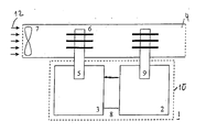
- the single figure shows very schematically a drive unit according to the invention.
- a drive unit 1 is housed in a common housing. It has, for example, a three-phase electric motor 2, for example, an asynchronous motor, synchronous motor, brushless DC motor, reluctance motor or the like.
- the electric motor may be associated with a transmission, which is not shown here.
- the connection 8 is a thermal insulator.
- a cooling channel 4 is provided at the left end of a fan 7 is provided for forced ventilation.
- the fan 7 is driven by a separate motor (not shown).
- a first heat pipe 5 is led into the control part 3 and extends out of the housing 10 into the cooling channel 4.
- a second heat pipe is led into the motor 10 and likewise extends into the cooling channel 4.
- the cooling air according to the Arrows 12 first strokes the cooling fins 6 of the heat pipe 5 along the heat pipe 9. That is, the heat pipe for the control part 3 is first cooled.
Landscapes
- Engineering & Computer Science (AREA)
- Power Engineering (AREA)
- Microelectronics & Electronic Packaging (AREA)
- Motor Or Generator Cooling System (AREA)
- Electric Propulsion And Braking For Vehicles (AREA)
Abstract
Description
- Die Erfindung bezieht sich auf eine Antriebseinheit insbesondere für Flurförderzeuge nach dem Patentanspruch 1.
- Batteriebetriebene Flurförderzeuge weisen zumeist mindestens einen elektrischen Fahrmotor auf. Gegebenenfalls ist ein weiterer Motor für eine elektrische Lenkung vorgesehen sowie ein Elektromotor zum Antrieb einer Hydraulikpumpe. Die verwendeten Motoren sind zum Beispiel Asynchronmotoren, Synchronmotoren, bürstenlose Gleichstrommotoren, Reluktanzmotoren usw..
- Da die Energiequelle eine Batterie ist und somit Gleichstrom bereitstellt, ist eine Umrichteranordnung erforderlich, um die Wechselstrom-Elektromotoren zu betreiben. In der vorliegenden Anmeldung wird die Umrichteranordnung als Steuerteil bezeichnet. Es ist bekannt, den Steuerteil für derartige Motoren außen am Gehäuse des Elektromotors anzubringen. Es ist jedoch auch bekannt, die Steuerteile mehr oder weniger in das Gehäuse der Elektromotoren zu integrieren. Wenn vorstehend eine Antriebseinheit gemeint ist, versteht sich, daß darunter entweder ein Elektromotor allein oder auch ein Elektromotor mit geeignetem Getriebe zu verstehen sind. Das Getriebe kann zum Beispiel innerhalb des Motorengehäuses angeordnet oder an das Motorengehäuse angeflanscht sein.
- Sowohl Elektromotor als auch Steuerteil erzeugen im Betrieb Wärme, die in geeigneter Weise abgeführt werden müssen. Es ist bekannt, hierfür Lüfter einzusetzen. Der Elektromotor kann durch einen Zwangslüfter, der auf der Welle des Motors sitzt, gekühlt werden. Es ist jedoch auch bekannt, einen separaten Lüfter zu verwenden, um zum Beispiel sowohl den Elektromotor als auch das Steuerteil zu kühlen. Eine solche Anordnung ist aus
EP 0 812 052 A1 bekannt geworden. - Aus
JP 2005 198 393 - Antriebseinheiten für Flurförderzeuge sollen nach Möglichkeit so klein wie möglich bauen. Je größer die Leistungsdichte ist, umso größer ist das Kühlproblem.
- Der Erfindung liegt die Aufgabe zugrunde, eine Antriebseinheit, insbesondere für Flurförderzeuge, zu schaffen, die klein baut und eine hohe Leistungsdichte aufweist und gleichwohl eine wirksame Kühlung aufweist.
- Diese Aufgabe wird durch die Merkmale des Patentanspruch 1 gelöst.
- Bei der Erfindung sind Elektromotor und Steuerteil in einem gemeinsamen Gehäuse angeordnet. Es ist ein separater Kühlkanal, vorzugsweise außerhalb des Gehäuses, vorgesehen. Ein thermisch hochwirksamer Leiter, gemäß einer Ausgestaltung der Erfindung eine Heatpipe, ist zwischen Antriebseinheit und Kühlkanal zur Ableitung von Wärme in dem Kühlkanal angeordnet.
- Die Integration elektrischer Steuerungen in die Antriebsmotoren bringt neben der Platzeinsparung den Vorteil, daß Schnittstellen reduziert werden. Bei der erfindungsgemäßen Lösung wird trotz kompakter Antriebseinheit die Wärme wirksam abgeführt.
- Nach einer Ausgestaltung der Erfindung ist die Heatpipe im Kühlkanal mit Kühlrippen versehen. Dadurch erfolgt eine wirksamere Übertragung der Wärme aus der Heatpipe auf den Kühlluftstrom im Kühlkanal. Der Kühlkanal kann nach einer weiteren Ausgestaltung der Erfindung mit einem Lüfter versehen werden.
- Nach einer anderen Ausgestaltung der Erfindung sind Antriebseinheit und Kühlkanal vertikal übereinander angeordnet. Dabei sorgt die Eigenkonvektion für eine ausreichende Luftströmung im daneben verlaufenden vertikalen Kühlkanal.
- Üblicherweise ist zwischen Elektromotor und Steuerteil eine mechanische Verbindung erforderlich. Diese erfolgt nach einer weiteren Ausgestaltung der Erfindung über mindestens einen thermischen Isolator.
- Die Heatpipe kann entweder für den Elektromotor und/oder den Steuerteil vorgesehen sein. Soll beides wirksam gekühlt werden, ist jeweils eine Heatpipe für Elektromotor und Steuerteil vorgesehen. Für diese Anordnung sieht eine weitere Ausgestaltung der Erfindung vor, daß die Heatpipes so im Kühlkanal angeordnet sind, daß die Kühlluft zunächst an der Heatpipe für den Steuerteil vorbeigeführt wird.
- Die Erfindung ist mit mehreren Vorteilen verbunden. Die Antriebseinheit kann äußerst kompakt ausgeführt werden. Der Kühlkanal kann effizient gestaltet werden, und ein Lüfter kann zwei Wärmequellen unterschiedlicher Temperatur kühlen. Die Dimensionierung der Kühlung gestaltet sich einfach.
- Ein Ausführungsbeispiel der Erfindung wird nachfolgend anhand einer Zeichnung näher erläutert.
- Die einzige Figur zeigt äußerst schematisch eine Antriebseinheit nach der Erfindung.
- Eine Antriebseinheit 1 ist in einem gemeinsamen Gehäuse untergebracht. Sie weist zum Beispiel einen dreiphasigen Elektromotor 2 auf, zum Beispiel einen Asynchronmotor, Synchronmotor, bürstenloser Gleichstrommotor, Reluktanzmotor oder dergleichen. Dem Elektromotor kann ein Getriebe zugeordnet sein, was hier nicht gezeigt ist. Ein Steuerteil 3, der insbesondere einen Umrichter für den Elektromotor 2 enthält, um den Elektromotor 2 von einer nicht gezeigten Batterie zu speisen, ist über eine mechanische Verbindung 8 mit dem Elektromotor verbunden. Die Verbindung 8 ist ein thermischer Isolator.
- Parallel zur Anordnung von Elektromotor 2 und Steuerteil 3 im Gehäuse 10 ist ein Kühlkanal 4 vorgesehen, an dessen linken Ende ein Lüfter 7 für eine Zwangsbelüftung vorgesehen ist. Der Lüfter 7 ist durch einen separaten Motor (nicht gezeigt) angetrieben.
- Eine erste Heatpipe 5 ist in das Steuerteil 3 hineingeführt und erstreckt sich aus dem Gehäuse 10 heraus in den Kühlkanal 4. Eine zweite Heatpipe ist in den Motor 10 hineingeführt und erstreckt sich ebenfalls in den Kühlkanal 4. Im Bereich des Kühlkanals 4 weisen die Heatpipes 5, 9 Kühlrippen 6 auf. Die Kühlluft gemäß den Pfeilen 12 streicht zunächst an den Kühlrippen 6 der Heatpipe 5 entlang zur Heatpipe 9. Das heißt, die Heatpipe für den Steuerteil 3 wird zunächst gekühlt.
Claims (10)
- Antriebseinheit mit einem Elektromotor und einem Steuerteil für den Elektromotor insbesondere für Flurförderzeuge, und ferner mit Lüftungsmitteln für den Elektromotor und/oder das Steuerteil, dadurch gekennzeichnet, daß Elektromotor (2) und Steuerteil (3) in einem gemeinsamen Gehäuse (10) angeordnet sind, ein separater Kühlkanal (4) vorgesehen ist und ein thermisch hochwirksamer Leiter zwischen Antriebseinheit und Kühlkanal (4) zur Ableitung von Wärme in dem Kühlkanal (4) angeordnet ist.
- Antriebseinheit nach Anspruch 1, dadurch gekennzeichnet, daß der thermische Leiter eine Heatpipe (5) ist.
- Antriebseinheit nach Anspruch 1 oder 2, dadurch gekennzeichnet, daß das Steuerteil einen Frequenzumrichter für eine dreiphasigen Elektromotor aufweist, wie Asynchronmotor, Synchronmotor, bürstenloser Gleichstrommotor, Reluktanzmotor usw.
- Antriebseinheit nach einem der Ansprüche 1 bis 3, dadurch gekennzeichnet, daß die Heatpipe (5, 9) im Kühlkanal (4) mit Kühlrippen (6) versehen ist.
- Antriebseinheit nach einem der Ansprüche 1 bis 4, dadurch gekennzeichnet, daß der Kühlkanal (4) einen Lüfter (7) aufweist.
- Antriebseinheit nach einem der Ansprüche 1 bis 5, dadurch gekennzeichnet, daß Elektromotor (2) und Steuerteil (3) übereinander angeordnet sind und der Kühlkanal daneben vertikal verläuft.
- Antriebseinheit nach einem der Ansprüche 1 bis 6, dadurch gekennzeichnet, daß eine mechanische Verbindung (8) zwischen Elektromotor (2) und Steuerteil (3) über eine thermische Isolation erfolgt.
- Antriebseinheit nach einem der Ansprüche 2 bis 7, dadurch gekennzeichnet, daß die Heatpipe (5, 9) zur Kühlung des Elektromotors (2) und/oder des Steuerteils (3) vorgesehen ist.
- Antriebseinheit nach einem der Ansprüche 2 bis 8, dadurch gekennzeichnet, daß für den Elektromotor (2) und für das Steuerteil (3) jeweils eine Heatpipe (5, 9) vorgesehen ist.
- Antriebseinheit nach Anspruch 9, dadurch gekennzeichnet, daß die Heatpipes (5, 9) im Kühlkanal (4) so angeordnet sind, daß die Kühlluft (12) zunächst an der Heatpipe für das Steuerteil (3) vorbeigeführt wird.
Applications Claiming Priority (1)
| Application Number | Priority Date | Filing Date | Title |
|---|---|---|---|
| DE102007010357A DE102007010357A1 (de) | 2007-03-03 | 2007-03-03 | Antriebseinheit insbesondere für Flurförderzeug |
Publications (3)
| Publication Number | Publication Date |
|---|---|
| EP1968170A2 true EP1968170A2 (de) | 2008-09-10 |
| EP1968170A3 EP1968170A3 (de) | 2010-10-20 |
| EP1968170B1 EP1968170B1 (de) | 2012-11-28 |
Family
ID=39402888
Family Applications (1)
| Application Number | Title | Priority Date | Filing Date |
|---|---|---|---|
| EP08002504A Not-in-force EP1968170B1 (de) | 2007-03-03 | 2008-02-12 | Antriebseinheit insbesondere für Flurförderzeug |
Country Status (2)
| Country | Link |
|---|---|
| EP (1) | EP1968170B1 (de) |
| DE (1) | DE102007010357A1 (de) |
Cited By (1)
| Publication number | Priority date | Publication date | Assignee | Title |
|---|---|---|---|---|
| FR2993430A1 (fr) * | 2012-07-11 | 2014-01-17 | Still Gmbh | Chariot de manutention electrique |
Families Citing this family (2)
| Publication number | Priority date | Publication date | Assignee | Title |
|---|---|---|---|---|
| TWI678867B (zh) | 2018-07-09 | 2019-12-01 | 群光電能科技股份有限公司 | 變頻器整合馬達 |
| DE102023132794A1 (de) * | 2023-11-24 | 2025-05-28 | Rolls-Royce Deutschland Ltd & Co Kg | Elektrische Antriebseinheit mit beheiztem Lufteinlass |
Citations (4)
| Publication number | Priority date | Publication date | Assignee | Title |
|---|---|---|---|---|
| SU1536479A1 (ru) | 1987-12-28 | 1990-01-15 | Всесоюзный научно-исследовательский проектно-конструкторский и технологический институт электромашиностроения | Электрическа машина |
| EP0812052A1 (de) | 1996-06-04 | 1997-12-10 | A. Dr. Stoev | Frequenzumrichter für eine Antriebsvorrichtung |
| JPH1127903A (ja) | 1997-07-03 | 1999-01-29 | Hitachi Ltd | 制御装置一体型電動機 |
| JP2005198393A (ja) | 2004-01-06 | 2005-07-21 | Nsk Ltd | 電動パワーステアリング装置の冷却装置 |
Family Cites Families (10)
| Publication number | Priority date | Publication date | Assignee | Title |
|---|---|---|---|---|
| DE2810222A1 (de) * | 1978-03-09 | 1979-09-13 | Bosch Gmbh Robert | Kuehlvorrichtung fuer elektrische maschinen |
| JPS6057956A (ja) * | 1983-09-09 | 1985-04-03 | Furukawa Electric Co Ltd:The | 半導体用ヒ−トパイプ放熱器 |
| JP2799030B2 (ja) * | 1990-02-15 | 1998-09-17 | 株式会社日立製作所 | 冷却装置付き回転機 |
| DE19634097C2 (de) * | 1996-08-23 | 1998-07-09 | Kostal Leopold Gmbh & Co Kg | Elektromotor |
| DE19704226B4 (de) * | 1997-02-05 | 2004-09-30 | Sew-Eurodrive Gmbh & Co. Kg | Klemmdeckelumrichter |
| JPH11164521A (ja) * | 1997-11-28 | 1999-06-18 | Toshiba Corp | インバータユニット付きモータ |
| JPH11313465A (ja) * | 1998-04-28 | 1999-11-09 | Toshiba Corp | 制御装置付きモータ |
| DE10310307A1 (de) * | 2002-03-18 | 2003-10-02 | Alstom Switzerland Ltd | Elektrische Maschine mit integrierter leistungselektronischer Einrichtung |
| DE10241420A1 (de) * | 2002-09-06 | 2004-03-18 | Still Gmbh | Flurförderzeug mit einem elektrischen Antrieb |
| DE102005041136B4 (de) * | 2005-08-30 | 2023-11-02 | Sew-Eurodrive Gmbh & Co Kg | Umrichtermotor und Verfahren |
-
2007
- 2007-03-03 DE DE102007010357A patent/DE102007010357A1/de not_active Withdrawn
-
2008
- 2008-02-12 EP EP08002504A patent/EP1968170B1/de not_active Not-in-force
Patent Citations (4)
| Publication number | Priority date | Publication date | Assignee | Title |
|---|---|---|---|---|
| SU1536479A1 (ru) | 1987-12-28 | 1990-01-15 | Всесоюзный научно-исследовательский проектно-конструкторский и технологический институт электромашиностроения | Электрическа машина |
| EP0812052A1 (de) | 1996-06-04 | 1997-12-10 | A. Dr. Stoev | Frequenzumrichter für eine Antriebsvorrichtung |
| JPH1127903A (ja) | 1997-07-03 | 1999-01-29 | Hitachi Ltd | 制御装置一体型電動機 |
| JP2005198393A (ja) | 2004-01-06 | 2005-07-21 | Nsk Ltd | 電動パワーステアリング装置の冷却装置 |
Cited By (1)
| Publication number | Priority date | Publication date | Assignee | Title |
|---|---|---|---|---|
| FR2993430A1 (fr) * | 2012-07-11 | 2014-01-17 | Still Gmbh | Chariot de manutention electrique |
Also Published As
| Publication number | Publication date |
|---|---|
| EP1968170B1 (de) | 2012-11-28 |
| EP1968170A3 (de) | 2010-10-20 |
| DE102007010357A1 (de) | 2008-09-04 |
Similar Documents
| Publication | Publication Date | Title |
|---|---|---|
| EP2308150B1 (de) | Elektrische maschine in hoher schutzart mit verbesserter läuferkühlung | |
| EP3207567B1 (de) | Antriebsvorrichtung für einen kraftfahrzeugantriebsstrang | |
| EP0820654B1 (de) | Linearmotor | |
| DE102010050348B4 (de) | Elektromotor und Bausatz zu seiner Herstellung | |
| EP3127223B2 (de) | Elektrische maschine | |
| DE102007054618A1 (de) | Stromrichter mit einem flüssiggekühlten Kondensator und einer Busstruktur mit niedriger Induktivität | |
| WO2017216020A1 (de) | Elektrischer achsantrieb für ein fahrzeug | |
| WO2021047718A1 (de) | Kühlbare elektrische antriebseinrichtung und antriebsanordnung | |
| DE102019207787A1 (de) | Elektrischer Antrieb für ein Fahrzeug in einem Gehäuse | |
| DE102013210559A1 (de) | Motor/Generator-Einheit | |
| DE102019205751A1 (de) | Elektrische Maschine mit einem Kunststoffkörper | |
| DE102019205762A1 (de) | Elektrische Maschine mit Drehmomentabstützung im Gehäuse | |
| EP1866728B1 (de) | Kühleinheit | |
| DE102019205752A1 (de) | Elektrische Maschine mit einem Kunststoffkörper | |
| EP3072219A1 (de) | Elektrische maschine mit rahmen und hülle | |
| WO2015078464A1 (de) | Hybridmodul mit integrierter leistungselektronik | |
| EP1968170B1 (de) | Antriebseinheit insbesondere für Flurförderzeug | |
| DE102021213004A1 (de) | Antriebsstrang für ein Kraftfahrzeug | |
| EP1709853B1 (de) | Kühleinrichtung für elektrische leistungseinheiten von elektrisch betriebenen fahrzeugen | |
| DE102019117155A1 (de) | Elektrischer Antrieb für ein Fahrzeug sowie Fahrzeug mit dem elektrischen Antrieb | |
| DE10320553A1 (de) | Linearmotor | |
| DE102020115905A1 (de) | Stator für eine elektrische Maschine zum Antrieb eines Kraftfahrzeugs | |
| EP2702845A1 (de) | Anordnung zum temperieren, insbesondere kühlen, von wärmeerzeugenden bauelementen mit einer kühlplatte | |
| DE102005032964A1 (de) | Umrichtermotor | |
| DE102012001389B4 (de) | Getriebe mit einem zentralen Gehäuseteil |
Legal Events
| Date | Code | Title | Description |
|---|---|---|---|
| PUAI | Public reference made under article 153(3) epc to a published international application that has entered the european phase |
Free format text: ORIGINAL CODE: 0009012 |
|
| AK | Designated contracting states |
Kind code of ref document: A2 Designated state(s): AT BE BG CH CY CZ DE DK EE ES FI FR GB GR HR HU IE IS IT LI LT LU LV MC MT NL NO PL PT RO SE SI SK TR |
|
| AX | Request for extension of the european patent |
Extension state: AL BA MK RS |
|
| PUAL | Search report despatched |
Free format text: ORIGINAL CODE: 0009013 |
|
| AK | Designated contracting states |
Kind code of ref document: A3 Designated state(s): AT BE BG CH CY CZ DE DK EE ES FI FR GB GR HR HU IE IS IT LI LT LU LV MC MT NL NO PL PT RO SE SI SK TR |
|
| AX | Request for extension of the european patent |
Extension state: AL BA MK RS |
|
| 17P | Request for examination filed |
Effective date: 20110419 |
|
| 17Q | First examination report despatched |
Effective date: 20110520 |
|
| AKX | Designation fees paid |
Designated state(s): DE FR GB IT |
|
| GRAJ | Information related to disapproval of communication of intention to grant by the applicant or resumption of examination proceedings by the epo deleted |
Free format text: ORIGINAL CODE: EPIDOSDIGR1 |
|
| GRAP | Despatch of communication of intention to grant a patent |
Free format text: ORIGINAL CODE: EPIDOSNIGR1 |
|
| GRAP | Despatch of communication of intention to grant a patent |
Free format text: ORIGINAL CODE: EPIDOSNIGR1 |
|
| GRAS | Grant fee paid |
Free format text: ORIGINAL CODE: EPIDOSNIGR3 |
|
| GRAA | (expected) grant |
Free format text: ORIGINAL CODE: 0009210 |
|
| AK | Designated contracting states |
Kind code of ref document: B1 Designated state(s): DE FR GB IT |
|
| REG | Reference to a national code |
Ref country code: GB Ref legal event code: FG4D Free format text: NOT ENGLISH |
|
| REG | Reference to a national code |
Ref country code: DE Ref legal event code: R096 Ref document number: 502008008730 Country of ref document: DE Effective date: 20130124 |
|
| PLBE | No opposition filed within time limit |
Free format text: ORIGINAL CODE: 0009261 |
|
| STAA | Information on the status of an ep patent application or granted ep patent |
Free format text: STATUS: NO OPPOSITION FILED WITHIN TIME LIMIT |
|
| 26N | No opposition filed |
Effective date: 20130829 |
|
| REG | Reference to a national code |
Ref country code: DE Ref legal event code: R097 Ref document number: 502008008730 Country of ref document: DE Effective date: 20130829 |
|
| REG | Reference to a national code |
Ref country code: FR Ref legal event code: PLFP Year of fee payment: 9 |
|
| REG | Reference to a national code |
Ref country code: FR Ref legal event code: PLFP Year of fee payment: 10 |
|
| PGFP | Annual fee paid to national office [announced via postgrant information from national office to epo] |
Ref country code: FR Payment date: 20170224 Year of fee payment: 10 |
|
| PGFP | Annual fee paid to national office [announced via postgrant information from national office to epo] |
Ref country code: GB Payment date: 20170228 Year of fee payment: 10 |
|
| PGFP | Annual fee paid to national office [announced via postgrant information from national office to epo] |
Ref country code: IT Payment date: 20170221 Year of fee payment: 10 |
|
| PGFP | Annual fee paid to national office [announced via postgrant information from national office to epo] |
Ref country code: DE Payment date: 20170428 Year of fee payment: 10 |
|
| REG | Reference to a national code |
Ref country code: DE Ref legal event code: R119 Ref document number: 502008008730 Country of ref document: DE |
|
| GBPC | Gb: european patent ceased through non-payment of renewal fee |
Effective date: 20180212 |
|
| REG | Reference to a national code |
Ref country code: FR Ref legal event code: ST Effective date: 20181031 |
|
| PG25 | Lapsed in a contracting state [announced via postgrant information from national office to epo] |
Ref country code: DE Free format text: LAPSE BECAUSE OF NON-PAYMENT OF DUE FEES Effective date: 20180901 |
|
| PG25 | Lapsed in a contracting state [announced via postgrant information from national office to epo] |
Ref country code: IT Free format text: LAPSE BECAUSE OF NON-PAYMENT OF DUE FEES Effective date: 20180212 Ref country code: FR Free format text: LAPSE BECAUSE OF NON-PAYMENT OF DUE FEES Effective date: 20180228 Ref country code: GB Free format text: LAPSE BECAUSE OF NON-PAYMENT OF DUE FEES Effective date: 20180212 |