EP1967668A2 - Über Translationsbewegung öffnende Rauchabzugsanlage - Google Patents
Über Translationsbewegung öffnende Rauchabzugsanlage Download PDFInfo
- Publication number
- EP1967668A2 EP1967668A2 EP08003838A EP08003838A EP1967668A2 EP 1967668 A2 EP1967668 A2 EP 1967668A2 EP 08003838 A EP08003838 A EP 08003838A EP 08003838 A EP08003838 A EP 08003838A EP 1967668 A2 EP1967668 A2 EP 1967668A2
- Authority
- EP
- European Patent Office
- Prior art keywords
- cable
- vault
- mechanisms
- pulleys
- sides
- Prior art date
- Legal status (The legal status is an assumption and is not a legal conclusion. Google has not performed a legal analysis and makes no representation as to the accuracy of the status listed.)
- Withdrawn
Links
- 239000000779 smoke Substances 0.000 title claims description 19
- 230000007246 mechanism Effects 0.000 claims abstract description 29
- 238000006073 displacement reaction Methods 0.000 claims abstract description 10
- 230000033001 locomotion Effects 0.000 claims description 13
- 230000000087 stabilizing effect Effects 0.000 claims description 11
- 230000000694 effects Effects 0.000 claims description 8
- 230000005540 biological transmission Effects 0.000 claims description 2
- 239000012530 fluid Substances 0.000 claims description 2
- 230000006641 stabilisation Effects 0.000 abstract description 16
- 238000011105 stabilization Methods 0.000 abstract description 15
- 238000000605 extraction Methods 0.000 description 13
- XEEYBQQBJWHFJM-UHFFFAOYSA-N Iron Chemical compound [Fe] XEEYBQQBJWHFJM-UHFFFAOYSA-N 0.000 description 6
- 230000000295 complement effect Effects 0.000 description 4
- 229910052742 iron Inorganic materials 0.000 description 3
- 240000008042 Zea mays Species 0.000 description 2
- 230000008901 benefit Effects 0.000 description 2
- UGFAIRIUMAVXCW-UHFFFAOYSA-N Carbon monoxide Chemical compound [O+]#[C-] UGFAIRIUMAVXCW-UHFFFAOYSA-N 0.000 description 1
- 244000236931 Cydonia oblonga Species 0.000 description 1
- 230000001154 acute effect Effects 0.000 description 1
- 238000005273 aeration Methods 0.000 description 1
- 230000001174 ascending effect Effects 0.000 description 1
- 238000010276 construction Methods 0.000 description 1
- 230000007547 defect Effects 0.000 description 1
- 239000003546 flue gas Substances 0.000 description 1
- 239000003517 fume Substances 0.000 description 1
- 238000004519 manufacturing process Methods 0.000 description 1
- 230000000630 rising effect Effects 0.000 description 1
- 230000001960 triggered effect Effects 0.000 description 1
Images

Classifications
-
- E—FIXED CONSTRUCTIONS
- E04—BUILDING
- E04D—ROOF COVERINGS; SKY-LIGHTS; GUTTERS; ROOF-WORKING TOOLS
- E04D13/00—Special arrangements or devices in connection with roof coverings; Protection against birds; Roof drainage ; Sky-lights
- E04D13/03—Sky-lights; Domes; Ventilating sky-lights
- E04D13/035—Sky-lights; Domes; Ventilating sky-lights characterised by having movable parts
- E04D13/0358—Sky-lights; Domes; Ventilating sky-lights characterised by having movable parts the parts moving, in their own plane, e.g. rolling or sliding, or moving in parallel planes with or without an additional movement, e.g. both pivoting and rolling or sliding
-
- E—FIXED CONSTRUCTIONS
- E04—BUILDING
- E04D—ROOF COVERINGS; SKY-LIGHTS; GUTTERS; ROOF-WORKING TOOLS
- E04D13/00—Special arrangements or devices in connection with roof coverings; Protection against birds; Roof drainage ; Sky-lights
- E04D13/03—Sky-lights; Domes; Ventilating sky-lights
- E04D13/035—Sky-lights; Domes; Ventilating sky-lights characterised by having movable parts
-
- E—FIXED CONSTRUCTIONS
- E05—LOCKS; KEYS; WINDOW OR DOOR FITTINGS; SAFES
- E05F—DEVICES FOR MOVING WINGS INTO OPEN OR CLOSED POSITION; CHECKS FOR WINGS; WING FITTINGS NOT OTHERWISE PROVIDED FOR, CONCERNED WITH THE FUNCTIONING OF THE WING
- E05F15/00—Power-operated mechanisms for wings
- E05F15/50—Power-operated mechanisms for wings using fluid-pressure actuators
- E05F15/57—Power-operated mechanisms for wings using fluid-pressure actuators for vertically-sliding wings
-
- E—FIXED CONSTRUCTIONS
- E05—LOCKS; KEYS; WINDOW OR DOOR FITTINGS; SAFES
- E05Y—INDEXING SCHEME ASSOCIATED WITH SUBCLASSES E05D AND E05F, RELATING TO CONSTRUCTION ELEMENTS, ELECTRIC CONTROL, POWER SUPPLY, POWER SIGNAL OR TRANSMISSION, USER INTERFACES, MOUNTING OR COUPLING, DETAILS, ACCESSORIES, AUXILIARY OPERATIONS NOT OTHERWISE PROVIDED FOR, APPLICATION THEREOF
- E05Y2201/00—Constructional elements; Accessories therefor
- E05Y2201/60—Suspension or transmission members; Accessories therefor
- E05Y2201/606—Accessories therefor
- E05Y2201/62—Synchronisation of suspension or transmission members
-
- E—FIXED CONSTRUCTIONS
- E05—LOCKS; KEYS; WINDOW OR DOOR FITTINGS; SAFES
- E05Y—INDEXING SCHEME ASSOCIATED WITH SUBCLASSES E05D AND E05F, RELATING TO CONSTRUCTION ELEMENTS, ELECTRIC CONTROL, POWER SUPPLY, POWER SIGNAL OR TRANSMISSION, USER INTERFACES, MOUNTING OR COUPLING, DETAILS, ACCESSORIES, AUXILIARY OPERATIONS NOT OTHERWISE PROVIDED FOR, APPLICATION THEREOF
- E05Y2201/00—Constructional elements; Accessories therefor
- E05Y2201/60—Suspension or transmission members; Accessories therefor
- E05Y2201/622—Suspension or transmission members elements
- E05Y2201/644—Flexible elongated pulling elements
- E05Y2201/654—Cables
-
- E—FIXED CONSTRUCTIONS
- E05—LOCKS; KEYS; WINDOW OR DOOR FITTINGS; SAFES
- E05Y—INDEXING SCHEME ASSOCIATED WITH SUBCLASSES E05D AND E05F, RELATING TO CONSTRUCTION ELEMENTS, ELECTRIC CONTROL, POWER SUPPLY, POWER SIGNAL OR TRANSMISSION, USER INTERFACES, MOUNTING OR COUPLING, DETAILS, ACCESSORIES, AUXILIARY OPERATIONS NOT OTHERWISE PROVIDED FOR, APPLICATION THEREOF
- E05Y2900/00—Application of doors, windows, wings or fittings thereof
- E05Y2900/10—Application of doors, windows, wings or fittings thereof for buildings or parts thereof
- E05Y2900/13—Type of wing
- E05Y2900/148—Windows
- E05Y2900/152—Roof windows
- E05Y2900/154—Skylights
Definitions
- the present invention relates to the design and manufacture of smoke extraction apparatus and equipment which are generally associated with them. More specifically, it relates to smoke extraction apparatus of the sunroof member type which can be mounted in vertical translation on a fixed structure.
- smoke extraction devices are widely used in the building industry, in particular to evacuate fumes produced during a fire. They operate by opening a flue gas duct which is normally closed by application of the opening element on a cooperating fixed frame. It is on the roof of buildings that they are found most often, at the top of stairwells or other risers in multi-family buildings, or on the terrace above industrial buildings and public buildings. This facilitates opening because the opening element is subjected to the pressure of the hot, smoke-laden air, which tends to rise. It follows that the device can function properly in smoke extraction under the simple effect of natural convection. But the invention does not exclude other situations, nor the use of fans or other means of assistance to the flow of stale air to evacuate.
- the opening element In smoke devices of the translating roof element type, the opening element, often referred to as a "dome” or “vault", is placed under the control of lifting means which lift it vertically away from it. a receiver frame on which it rests in the closed position.
- Particularly suitable lifting means involve two similar mechanisms acting on two opposite sides of the arch member.
- cooperating elements, arch element and receiver frame which are of quadrangular shape, preferably with right angles between the adjacent sides, are considered. It will therefore be admitted here, for the sake of clarity, that the two opposite sides on which the lifting mechanisms act are parallel; and that they are advantageously symmetrical with respect to a median axis of the quadrangular shape.
- the two sides in question will here be called lateral sides, or lifting sides. They are symmetrical, on either side of the median axis, or longitudinal axis.
- any smoke extraction device must be able to open easily at any time, in complete safety, and remain available and ready to perform its duties effectively for many years.
- any defect of stability of the element of vault during its displacements is because of vibrations which are likely to cause a blockage of the mechanisms of lifting, from where an incapacity to function correctly thereafter.
- the invention proposes to combine lifting means for controlling the movements of the arch element relative to the fixed curb with means for stabilizing the arch element during its movements. , which all the better complement the effects of the lifting means when they are advantageously of the type with deployable mechanisms acting symmetrically on two lateral sides of the vault element to lift it away from the curb and control its return in closed position on it, as is known per se from a prior art which is illustrated, for example, by the patent document EP 0 801 183 .
- the invention proposes to act to do this by balancing between two opposite sides of the vault element, in terms of distance traveled with respect to its receiving structure in the closed position, by using wire elements forced to describe circuits multiplying efforts.
- stabilizing means it is possible to maintain the equality of the distances traveled by these two opposite sides of the arch element during the movements of the latter between its extreme positions, closed position at rest on the fixed receiver frame and open position. after uprising: maximum.
- These two sides of the vault may be the two transverse sides which, in a quadrangular form, are complementary to the two lifting sides between their respective ends, but most often it will be preferable to acting in stabilization of the vault on the same lateral sides of the latter as in uprising, especially since it is advantageous for these lateral sides to be reinforced by means of stiffening which are then not necessary on the transverse sides.
- the wire elements are constituted in particular by cables, where appropriate by two different cable sections or by two different parts of the same cable,
- said stress reducing circuits can be formed on the same closed loop path in which there are two symmetrical parts which are respectively associated with the two balancing sides of the vault element.
- the invention also proposes to combine control means of a different nature to, respectively, ensure the lifting by action on the lifting sides and ensure stabilization by acting on the balancing sides. It thus provides, in particular, in preferred embodiments, to act on the former by the effect of fluid pressure, in particular using lifting mechanisms with articulated elements deployable under the control of pneumatic cylinders, and to act on the second directly by mechanical equilibrium displacement means: each of the balancing sides with respect to a fixed reference level can thus benefit at best from the power advantages that it is known to appreciate pneumatic cylinders while overcoming their shortcomings thanks to the fineness of precision that can provide the balancing means constructed and operated in accordance with the present invention.
- the stabilizing means consist essentially of a wire element, of the cord or cable type, of constant length, which is kept moving on itself on a closed loop circuit comprising two parts. symmetrical respectively associated with the two balancing sides of the vault element, each of said parts being subject to present a fixed point relative to the curb on a vertical component portion of its path.
- the circuit imposed on the cable is preferably of the stress reduction type.
- the invention is expressed by the fact that such a wire element is made in the form of two similar cable sections, so that the stabilization means comprise at least one cable section extending between two points.
- fixed references located respectively on each side of the apparatus by describing multiplier circuits of effort in opposite directions, one having effect in the direction of the rise, the other in the direction of the descent of the element of vault.
- the smoke extraction apparatus responds to various secondary characteristics, which apply separately or in combination in the same research to meet the needs of industrial practice, particularly in terms of reliability of construction. and operation of the apparatus as a whole and absence of harmful vibrations during the lift or the vault element.
- the figures all refer to the position of the apparatus when it is mounted on a horizontal terrace constituting the roof of a building
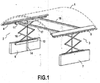
- the vault element is represented in the form of a dome 1 of conventional shape, around rectangular, and more particularly square, which is movable in vertical translation over a bay formed through the roof and surrounded by a curb complementing the dome.
- the dome In the rest position, when the device is normally closed, the dome rests on the curb, in waterproof support by its four sides on the four homologous sides of the curb.
- the two lifting mechanisms 2 and 3 control the smoke extraction device by vertical translation of the dome.1 in both directions, the opening to move away from the curb by lifting and closing to bring it to rest in a sealed position on it. For this, they each act respectively on a corresponding lateral side 4 or 5 of the dome.
- the dome 1 covers a rectangular area, or more particularly square, and both opposite sides of the dome (4 and 5) are straight and horizontal, in a symmetrical arrangement with respect to a median axis that will be said here longitudinal. Their orientation remains horizontal during their displacement.
- the corresponding sides of the receiving frame of the curb (not shown) are therefore also horizontal.
- Each lifting mechanism for example the one on the left bearing the reference 2 on the figure 1 is essentially constituted by a deployable mechanism with articulated rods bearing, on the one hand on the corresponding lateral side 4 of the dome, rigidified for this purpose by an edge iron, and on the other hand on a fixed support 6 (or 7 for mechanism 3 on the right of the figure 1 ).
- a deployable mechanism with articulated rods bearing on the one hand on the corresponding lateral side 4 of the dome, rigidified for this purpose by an edge iron, and on the other hand on a fixed support 6 (or 7 for mechanism 3 on the right of the figure 1 ).
- a fixed support 6 or 7 for mechanism 3 on the right of the figure 1
- the latter is part as the curb of the fixed structure of the smoke extraction apparatus. It is of course the same for the other fixed support 7, arranged symmetrically in a corresponding situation with respect to the mechanism 3 driving the opposite side 5 of the dome 1.
- the deployable mechanism is illustrated on the figure 1 by a realization in double cross of rods articulated between them.
- the figure 1 still shows, and there better on the left side than on the right side, a cylinder 14, which is generally embodied by a double-acting pneumatic cylinder whose piston slides vertically in the fixed piston body.
- the mechanism 2 is deployed or retracted under the action of this jack, whose piston rod is connected to the movable casing 11 in the middle of the side, 4 of the dome; so that it drives the latter and thus controls the movements of the upper case 11 of the articulated rod mechanism relative to its fixed lower case 12.
- a double cross similar to that of the figure 1 is combined with an articulated parallelogram, by adding two articulated rods to close the parallelogram between two parallel articulated rods respectively from each cross of the double cross.
- This solution provides better stability in the longitudinal direction of the dome by allowing longer reach supports at both ends of the support articulated structure.
- the dome translation control means comprise for each of its lateral sides a deployable structure of articulated rods designed for balanced motion transmission in the longitudinal direction along the corresponding lateral side of the dome.
- the mechanism On each side of the apparatus, the mechanism then integrates longitudinal stabilization means of the dome during its movements, the effects of which are advantageously combined with those of the means according to the invention ensuring a transverse stabilization between the two lateral sides of the dome. as it will now be described.
- the means of the stabilization device have not been represented on the figure 1 to better show the constitution of the lifting means, while the latter is in itself conventional. It will be noted, however, that we are here in a situation in which, for a dome of rectangular (and more particularly square) right-of-way, the complementary sides to the lifting sides are curved. Therefore, it is also these lifting sides that will play the role of balancing sides for transverse stabilization. Furthermore, there are provided two crosspieces 17 and 18 rigidly connecting the two sides 4 and 5 in a horizontal plane, for questions relating to the strength of the dome and the accuracy of its movement controlled by the two lifting mechanisms.
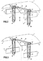
- FIGS. 2 and 3 are there to represent the stabilization means that complete the lifting mechanisms in accordance with the invention. There is no representation of the deployable mechanisms and we have only symbolically illustrated the dome 1. On the other hand, it was recalled the presence of the two supports 6 and 7, which are fixed under the roof which is equipped with the smoke evacuation device described, because these two support supports of the lifting mechanisms also constitute fixed reference points for the stabilization device.
- the means provided herein, according to the invention, for stabilizing the dome during its movements: and to prevent the parts of the smoke extraction device as a whole from suffering from vibration phenomena, comprise two symmetrical parts 8 and 9, which act respectively on the side 4 of the dome for the left part 8, visible on the left of the figures, and on the side 5 of the dome for the opposite right part 9.
- the fixed support 7 associated with the latter was only mentioned, by dashed lines; to not hide the elements of the stabilization device. These elements are indeed behind the support 7 on this side, while the elements of the left part 8 are visible in front of the fixed support 6.
- the stabilizing device consists essentially of a continuous cable 20, which is seen to buckle on itself by describing a closed-loop circuit following a path imposed by two sets of pulleys respectively of the two symmetrical parts 8 and 9.
- it is provided on each side of the device to pass the cable around three pulleys, each in free rotation about its axis, but as in a hoist, the pulleys could be more numerous on each portion of circuit thus defined.
- each set of pulleys has two upper pulleys; rotatably mounted about a longitudinal axis integral with the edge iron of the corresponding side of the dome respectively 4 on the left and 5 'on the right
- the references 24 and 25 have been attributed to the pulleys which guide the strand 21, visible forwards in the figures, between the left part and the right part of the stabilizing device, while the homologous pulleys guiding the rear section 22 carry the references 26 and 27.
- the force reduction circuit imposed on the cable is materialized by a third pulley, visible at 28 for the left part of the stabilization device and at 29 for the right part.
- the distance between this lower pulley and the upper pulleys is constant, the three pulleys being mounted on the same movable support moving relative to the fixed curb at the same time as the opening of the device.
- this distance between the two pulley levels is the same on both sides of the device.
- each set of pulleys comprises in the upper part two pulleys in free rotation on axes which are fixed on the edge of the corresponding lateral side of the dome and an intermediate pulley on the cable path that is carried at the lower end of a support bar oriented vertically from the lateral side of the dome and secured to the latter.
- This is how we represented on Figures 2 and 3 four uprights constituting such supports pulleys, in particular the uprights 31 and 32 visible on the right of the figures.
- the rear amount 32 is chosen for example.
- it is also visible on the right side of Figures 2A and 3A , it is bent at right angles to its upper end to be welded to the edge iron consolidating the dome on its corresponding lateral side. The corresponding set of pulleys is thus secured to the opening.
- the cable In operation, the cable never travels the entire circuit in a closed loop. Its movements on itself are limited to a movement back and forth of each of the two strands, one from a fixed point of its own, the other to another fixed point of its own. . In their part following the transverse direction of the dome, each one moves on itself alternately in one direction and in the other depending on whether the opening dome moves up or down
- the cable 20 is fixedly attached to a stud 34 which is provided for this purpose on the wall of the support 6, and that on the other side, it is also fixedly attached to another stud 35, which is integral with the fixed support 7.
- the assembly divides the cable 20 into two sections of equal lengths each extending from one to the other of the fixed points respectively following two force reduction circuits, the ascending parts and descendants are distributed in a complementary manner on each side of the moving dome.
- the invention is in no way limited by the features which have been specified in the foregoing description.
Landscapes
- Engineering & Computer Science (AREA)
- Architecture (AREA)
- Civil Engineering (AREA)
- Structural Engineering (AREA)
- Buildings Adapted To Withstand Abnormal External Influences (AREA)
- Power-Operated Mechanisms For Wings (AREA)
- Emergency Lowering Means (AREA)
Applications Claiming Priority (1)
| Application Number | Priority Date | Filing Date | Title |
|---|---|---|---|
| FR0701671A FR2913441B1 (fr) | 2007-03-07 | 2007-03-07 | Appareil de desenfumage ouvrant par translation |
Publications (2)
| Publication Number | Publication Date |
|---|---|
| EP1967668A2 true EP1967668A2 (de) | 2008-09-10 |
| EP1967668A3 EP1967668A3 (de) | 2010-01-20 |
Family
ID=38582055
Family Applications (1)
| Application Number | Title | Priority Date | Filing Date |
|---|---|---|---|
| EP08003838A Withdrawn EP1967668A3 (de) | 2007-03-07 | 2008-02-29 | Über Translationsbewegung öffnende Rauchabzugsanlage |
Country Status (2)
| Country | Link |
|---|---|
| EP (1) | EP1967668A3 (de) |
| FR (1) | FR2913441B1 (de) |
Cited By (1)
| Publication number | Priority date | Publication date | Assignee | Title |
|---|---|---|---|---|
| CN108590729A (zh) * | 2018-03-12 | 2018-09-28 | 中铁第四勘察设计院集团有限公司 | 一种高密闭型排烟口装置 |
Citations (1)
| Publication number | Priority date | Publication date | Assignee | Title |
|---|---|---|---|---|
| EP0801183A1 (de) | 1996-04-12 | 1997-10-15 | Cronier Application | Rauchabzugsvorrichtung für ein langes Tonnengewölbe |
Family Cites Families (4)
| Publication number | Priority date | Publication date | Assignee | Title |
|---|---|---|---|---|
| GB191114576A (en) * | 1911-06-20 | 1911-09-14 | Otto Herrmann | Improvements in Roof-lights. |
| US2328659A (en) * | 1940-06-10 | 1943-09-07 | Safe Play Company Inc | Closure |
| FR1286457A (fr) * | 1961-04-18 | 1962-03-02 | Klaus Esser Bau Und Industrieb | Coupole transparente avec fenêtre décollable |
| FR2777028B1 (fr) * | 1998-04-06 | 2000-05-12 | Mecanique De Poinsenot Sarl Co | Dispositif d'exutoire de desenfumage |
-
2007
- 2007-03-07 FR FR0701671A patent/FR2913441B1/fr not_active Expired - Fee Related
-
2008
- 2008-02-29 EP EP08003838A patent/EP1967668A3/de not_active Withdrawn
Patent Citations (1)
| Publication number | Priority date | Publication date | Assignee | Title |
|---|---|---|---|---|
| EP0801183A1 (de) | 1996-04-12 | 1997-10-15 | Cronier Application | Rauchabzugsvorrichtung für ein langes Tonnengewölbe |
Cited By (1)
| Publication number | Priority date | Publication date | Assignee | Title |
|---|---|---|---|---|
| CN108590729A (zh) * | 2018-03-12 | 2018-09-28 | 中铁第四勘察设计院集团有限公司 | 一种高密闭型排烟口装置 |
Also Published As
| Publication number | Publication date |
|---|---|
| FR2913441A1 (fr) | 2008-09-12 |
| FR2913441B1 (fr) | 2010-10-08 |
| EP1967668A3 (de) | 2010-01-20 |
Similar Documents
| Publication | Publication Date | Title |
|---|---|---|
| EP1434916A1 (de) | Zwischen zwei positionen, eine auf dem boden aufliegende und eine schwimmende, bewegliche gebäudeanordnung | |
| CA2197034A1 (fr) | Remorque deployable en gradins | |
| EP1644280B1 (de) | Aufzug | |
| EP2771235B1 (de) | Anlage zur verankerung einer schwimmenden plattform im boden | |
| FR2954789A1 (fr) | Abri mobile pour piscine | |
| EP0969165B1 (de) | Vorrichtung zum Heben und Manipulieren von Platten zum Verkleiden von Decken | |
| WO1999056999A1 (fr) | Ensemble bidirectionnel de guidage le long d'un rail autorisant un deport lateral pour un essieu routier | |
| EP1967668A2 (de) | Über Translationsbewegung öffnende Rauchabzugsanlage | |
| EP2001710B1 (de) | Hubfahrzeug für in grossen höhen arbeitende personen | |
| FR2679894A1 (fr) | Jambe de stabilisation formant pied d'appui pour une structure transportable telle qu'un abri technique par exemple. | |
| EP0002865B1 (de) | Vorrichtung zur beliebigen Umwandlung eines Saales | |
| FR2689073A1 (fr) | Appareillage de manutention de charges allongées sur le toit d'un véhicule. | |
| FR2704105A1 (fr) | Ensemble pour le basculement d'armoires de contrôle, escamotable en fosse. | |
| FR3004480A1 (fr) | Structure pliable de travail en encorbellement integrant un dispositif d'aide au depliage d'un auvent | |
| FR3040410B1 (fr) | Plancher mobile pour piscine et piscine equipee d'un tel plancher | |
| FR2679544A1 (fr) | Appareilage autonome permettant d'extraire et deplacer des elements encastres dans le sol, tels que plaques d'egouts, grilles. | |
| FR2581303A1 (fr) | Structure de vitrine | |
| FR2913240A1 (fr) | Barriere deployable. | |
| WO1994025706A1 (fr) | Tribune telescopique a pente variable et sieges escamotables | |
| FR3021337A1 (fr) | Portique de coffrage et coffrage muni d'un tel portique, procede de decoffrage, procede de fabrication de portion de mur ou de batiment, portion de mur et batiment. | |
| FR3039530A1 (fr) | Dispositif d'elevation | |
| FR2474576A1 (fr) | Dispositif de protection contre les agressions | |
| EP0758428A1 (de) | Lenkvorrichtung fuer treppenleiterfahrzeug | |
| FR2744638A1 (fr) | Plan d'escalade mobile | |
| FR2981381A1 (fr) | Dispositif pour l'installation d'un fond mobile dans un bassin et fond mobile pour un tel bassin |
Legal Events
| Date | Code | Title | Description |
|---|---|---|---|
| PUAI | Public reference made under article 153(3) epc to a published international application that has entered the european phase |
Free format text: ORIGINAL CODE: 0009012 |
|
| AK | Designated contracting states |
Kind code of ref document: A2 Designated state(s): AT BE BG CH CY CZ DE DK EE ES FI FR GB GR HR HU IE IS IT LI LT LU LV MC MT NL NO PL PT RO SE SI SK TR |
|
| AX | Request for extension of the european patent |
Extension state: AL BA MK RS |
|
| PUAL | Search report despatched |
Free format text: ORIGINAL CODE: 0009013 |
|
| AK | Designated contracting states |
Kind code of ref document: A3 Designated state(s): AT BE BG CH CY CZ DE DK EE ES FI FR GB GR HR HU IE IS IT LI LT LU LV MC MT NL NO PL PT RO SE SI SK TR |
|
| AX | Request for extension of the european patent |
Extension state: AL BA MK RS |
|
| 17P | Request for examination filed |
Effective date: 20100719 |
|
| AKX | Designation fees paid |
Designated state(s): AT BE BG CH CY CZ DE DK EE ES FI FR GB GR HR HU IE IS IT LI LT LU LV MC MT NL NO PL PT RO SE SI SK TR |
|
| STAA | Information on the status of an ep patent application or granted ep patent |
Free format text: STATUS: THE APPLICATION IS DEEMED TO BE WITHDRAWN |
|
| 18D | Application deemed to be withdrawn |
Effective date: 20130903 |