EP1967394A1 - Federfangvorrichtung - Google Patents
Federfangvorrichtung Download PDFInfo
- Publication number
- EP1967394A1 EP1967394A1 EP08003062A EP08003062A EP1967394A1 EP 1967394 A1 EP1967394 A1 EP 1967394A1 EP 08003062 A EP08003062 A EP 08003062A EP 08003062 A EP08003062 A EP 08003062A EP 1967394 A1 EP1967394 A1 EP 1967394A1
- Authority
- EP
- European Patent Office
- Prior art keywords
- rocker
- bearing block
- leaf spring
- spring
- stop
- Prior art date
- Legal status (The legal status is an assumption and is not a legal conclusion. Google has not performed a legal analysis and makes no representation as to the accuracy of the status listed.)
- Granted
Links
Images


Classifications
-
- B—PERFORMING OPERATIONS; TRANSPORTING
- B60—VEHICLES IN GENERAL
- B60G—VEHICLE SUSPENSION ARRANGEMENTS
- B60G11/00—Resilient suspensions characterised by arrangement, location or kind of springs
- B60G11/02—Resilient suspensions characterised by arrangement, location or kind of springs having leaf springs only
- B60G11/04—Resilient suspensions characterised by arrangement, location or kind of springs having leaf springs only arranged substantially parallel to the longitudinal axis of the vehicle
-
- B—PERFORMING OPERATIONS; TRANSPORTING
- B60—VEHICLES IN GENERAL
- B60G—VEHICLE SUSPENSION ARRANGEMENTS
- B60G11/00—Resilient suspensions characterised by arrangement, location or kind of springs
- B60G11/02—Resilient suspensions characterised by arrangement, location or kind of springs having leaf springs only
- B60G11/10—Resilient suspensions characterised by arrangement, location or kind of springs having leaf springs only characterised by means specially adapted for attaching the spring to axle or sprung part of the vehicle
- B60G11/12—Links, pins, or bushes
-
- B—PERFORMING OPERATIONS; TRANSPORTING
- B60—VEHICLES IN GENERAL
- B60G—VEHICLE SUSPENSION ARRANGEMENTS
- B60G2202/00—Indexing codes relating to the type of spring, damper or actuator
- B60G2202/10—Type of spring
- B60G2202/11—Leaf spring
- B60G2202/112—Leaf spring longitudinally arranged
-
- B—PERFORMING OPERATIONS; TRANSPORTING
- B60—VEHICLES IN GENERAL
- B60G—VEHICLE SUSPENSION ARRANGEMENTS
- B60G2204/00—Indexing codes related to suspensions per se or to auxiliary parts
- B60G2204/10—Mounting of suspension elements
- B60G2204/12—Mounting of springs or dampers
- B60G2204/121—Mounting of leaf springs
-
- B—PERFORMING OPERATIONS; TRANSPORTING
- B60—VEHICLES IN GENERAL
- B60G—VEHICLE SUSPENSION ARRANGEMENTS
- B60G2204/00—Indexing codes related to suspensions per se or to auxiliary parts
- B60G2204/40—Auxiliary suspension parts; Adjustment of suspensions
- B60G2204/45—Stops limiting travel
Definitions
- the invention relates to a sprung suspension of a rigid axle on the chassis frame of a commercial vehicle, in particular a truck or bus with the features specified in the preamble of claim 1 Art.
- a sprung rigid axle suspension of a vehicle in which the axle body is fastened to the bottom of a leaf spring, which is hinged at the front to a frame-fixed bracket and the rear at a lower bearing point of a rocker. This is hinged via an upper bearing pivotally attached to a frame-fixed rear bearing block.
- a spring catch device is provided which is effective at the break of the leaf spring at the front attachment area.
- the spring catching device consists of a catch bolt which is arranged on the rear bearing block above and spaced from the upper bearing point of the rocker and a rocker which is extended up to the area of the catch bolt by a catching area.
- At said catch area at least one stop surface is provided at the level of the catch bolt, which comes at the spring bolt on the catch bolt to the plant, but with intact leaf spring in each compression state of the frame with respect to the axis of the rigid axle a more or less large measure of the catch bolt remains.
- a suspension would be advantageous, which would offer a more stable and less expensive stop surface.
- the present invention is based on the object to provide a suspension of a rigid axle of a commercial vehicle, which combined the advantages mentioned above in itself.
- the object is achieved by a suspension with the features of the characterizing part of claim 1.
- the suspension of the rigid axle according to the invention requires a smaller number of parts, since the stop (s) can be produced in one piece with the bearing block. The following is an attack.
- two opposing stops are arranged on the bearing block, each of which limits the pivoting range of the rocker in one of the two mutually opposite pivoting directions.
- the longitudinal displacement of the broken leaf spring can be set in this way to avoid major consequential damage from the outset. An uncontrolled back and forth shift of the broken leaf spring is prevented by arranging another stop.
- the stops can be adapted in their strength and size to the size and weight and the design of the leaf spring (for example: single-leaf or multi-leaf leaf spring).
- the stop has a contact surface whose contour coincides with the contour of the surface of the spring eye.
- the rigid axle is shown by reference numeral 4 and is arranged on the underside of the leaf spring 5. To cushion the rigid axle 4 is used in addition to the leaf spring 5 of the shock absorber 6.
- the rigid axle 4 and the shock absorber 6 are arranged approximately in the middle between the front and rear bearing block 2 and 3. Seen from the direction of travel 7, behind the shock absorber 6 is a Federwegbegrenzer 8 is arranged.
- the front and the rear end 9 and 10 of the leaf spring 5 each have a spring eye 11 and 12.
- the leaf spring 5 engages their front spring eye 11 directly on the frame-fixed bearing block 2.
- the frame bears the reference numeral 1.
- Fig. 1 shows a suspension with leaf spring 5 in the intact state, which has a distance 16 between the rear spring eye 12 and a stop 17.
- the bearing block 3 has in the example of Fig. 1 two opposing front and rear stops 18 and 17.
- the maximum pivoting range 20 of the rocker 13 is determined, which limits the longitudinal displacement 21 of the leaf spring 5 in and against the direction of travel 7.
- the stops 17 and 18 engage in the pivoting portion 20 of the rocker 13 a.
- the leaf spring 5 is stepped horizontally in the regions 28.
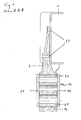
- Fig. 2 shows in enlarged scale the rear bearing block 3 as in Fig. 1 shown.
- the rear spring eye 12 With an intact leaf spring 5, the rear spring eye 12 at a distance 16 relative to the stop 17. If the spring travel 22 of the leaf spring 5 is fully utilized, a longitudinal displacement 21 of the leaf spring 5, in which, however, a distance 16 between the spring eye 12 and stop 17 is maintained. Depending on the longitudinal displacement 21, the distance 16 may be between 5 mm and 9 mm. However, this information is only exemplary in nature and may be replaced by other values.
- the rear bearing block 3 has two stops 17 and 18 which delimit the pivoting area 20 of the rocker 13. The storage of the ends 15 and 14 of the rocker 13 takes place as in Fig. 1 described on the bearing block 3 and the spring eye 12.
- the bearing blocks 2 and 3 are in the Fig. 1-3 23 is conceivable, instead of the screw 23, the connection, for. B. produce by welding.
- Fig. 3 shows the rear bracket 3 as in Fig. 2 with the difference that it is assumed that a broken leaf spring 5, whereby a longitudinal displacement 21 takes place counter to the direction of travel 7 and the spring eye 12 comes to rest with the stop 17 of the rear bearing block 3.
- the stop 17 limited in Fig. 3 the pivoting region 20 against the direction of travel 7, in which the stop 17 engages in the pivoting region 20 of the rocker 13.
- the stop 18 limits the pivoting range 20 in the direction of travel 7 Fig. 3 are the section lines AA and BB shown on which the Fig. 4 and 5 Respectively.
- Fig. 4 shows in schematic form the section along the lines AA from the Fig. 3 , With reference number 1 while the vehicle frame is shown, the z. B. is firmly connected via the screws 23 to the rear bearing block 3.
- the rocker 13 has two connecting webs 24, 25 which connect the two rocker sides 26 and 27. About the upper connecting web 24, the rocker 13 is hinged to the bearing block 3. The articulation of the rocker 13 on the rear spring eye 12 via the connecting web 25th
- Fig. 5 shows in schematic form the section along the lines BB from the Fig. 3 , Reference numeral 5, the leaf spring is shown, which tapers in the region of the rocker 13.
- the stops 17 and 18 engage in the pivoting portion 20 of the rocker 13.
- Fig. 5 is the other, namely the rear end 15 of the rocker 13, with which the rocker 13 is hinged to the rear bearing block 3.
- the hatched area shows the area 28 of the leaf spring 5, in which the leaf spring 5 is stepped in the horizontal.
Landscapes
- Engineering & Computer Science (AREA)
- Mechanical Engineering (AREA)
- Vehicle Body Suspensions (AREA)
- Harvester Elements (AREA)
- Catching Or Destruction (AREA)
- Sink And Installation For Waste Water (AREA)
- Automobile Manufacture Line, Endless Track Vehicle, Trailer (AREA)
- Pens And Brushes (AREA)
- Mechanical Pencils And Projecting And Retracting Systems Therefor, And Multi-System Writing Instruments (AREA)
- Springs (AREA)
Abstract
Description
- Die Erfindung betrifft eine gefederte Aufhängung einer Starrachse am Fahrgestellrahmen eines Nutzfahrzeugs, insbesondere eines Lastwagens oder Omnibusses mit den Merkmalen der im Oberbegriff des Anspruchs 1 angegebenen Art.
- Die Fahrsicherheit ist auch bei der Entwicklung von Nutzfahrzeugen ein wichtiges Thema. Dabei spielt unter anderem die Auslegung der Aufhängung der Starrachsen eine große Rolle. Bei der Aufhängung der Starrachse des Nutzfahrzeugs wirken auf die dort eingesetzten Blattfedern bedeutende horizontale und vertikal Kräfte ein. Bricht eine Blattfeder, kann bei herkömmlichen Nutzfahrzeugen die Verschiebung der Starrachse in horizontaler Richtung die Folge sein.
- Aus der
AT 413 362 B - Vorteilhaft wäre eine Aufhängung, die eine stabilere und weniger aufwendige Anschlagfläche böte.
- Vor diesem Hintergrund liegt der vorliegenden Erfindung die Aufgabe zu Grunde, eine Aufhängung einer Starrachse eines Nutzfahrzeugs zu schaffen, die die oben genannten Vorteile in sich vereinigte. Die Aufgabe wird erfindungsgemäß durch eine Aufhängung mit den Merkmalen des kennzeichnenden Teils des Anspruchs 1 gelöst.
- Die erfindungsgemäße Aufhängung der Starrachse erfordert eine geringere Teilevielfalt, da der/die Anschläge einstückig mit dem Lagerbock herstellbar sind. Im Folgenden wird von einem Anschlag ausgegangen.
- Durch Anordnung des Anschlags am Lagerbock wird der längsverschobenen Blattfeder eine höhere Widerstandskraft entgegengesetzt, da sich der Anschlag mit seinem Rücken am Lagerbock abstützt. Die Gefahr, dass der Anschlag durch die längsverschobene Blattfeder abgerissen wird, wird deutlich reduziert.
- Nach einer anderen Ausführungsform der Erfindung sind am Lagerbock zwei einander entgegen gesetzte Anschläge angeordnet, von denen jeder den Schwenkbereich der Schwinge in einer der beiden einander entgegen gesetzten Schwenkrichtungen begrenzt. Die Längsverschiebung der gebrochenen Blattfeder kann auf diese Weise zur Vermeidung größerer Folgeschäden von vorne herein festgelegt werden. Eine unkontrollierte Vor- und Zurückverschiebung der gebrochenen Blattfeder wird durch Anordnung eines weiteren Anschlags unterbunden. Die Anschläge können in ihrer Stärke und Größe an die Größe und das Gewicht sowie die Ausführung der Blattfeder angepasst werden (z. B.: einblättrige oder mehrblättrige Blattfeder).
- Nach einer anderen Ausführungsform der Erfindung weist der Anschlag eine Anlagefläche auf, deren Kontur mit der Kontur der Oberfläche des Federauges übereinstimmt. Hierdurch wird eine verbesserte Anlage des Federauges am Anschlag erreicht.
- Nachstehend ist die Erfindung anhand mehrer in der Zeichnung dargestellter Ausführungsbeispiele näher erläutert. Hierbei zeigen:
- Fig. 1
- In schematischer Darstellung die Aufhängung der Starrachse,
- Fig. 2
- In schematischer Darstellung den hinteren Lagerbock bei intakter Blattfeder,
- Fig. 3
- In schematischer Darstellung den hinteren Lagerbock bei Längsverschiebung der Blattfeder,
- Fig. 4
- In schematischer Darstellung den Schnitt A-A aus
Fig. 3 und - Fig. 5
- In schematischer Darstellung den Schnitt B-B aus
Fig. 3 . - Fig. 1
- zeigt die erfindungsgemäße Aufhängung der Starrachse mit einem Fahrzeugrahmen 1, an dem je ein vorderer und hinterer weiterer Lagerbock (2 und 3) angeordnet sind.
- Die Starrachse ist mit Bezugsziffer 4 dargestellt und ist an der Unterseite der Blattfeder 5 angeordnet. Zur Abfederung der Starrachse 4 dient der neben der Blattfeder 5 der Stoßdämpfer 6. Die Starrachse 4 und der Stoßdämpfer 6 sind in etwa mittig zwischen dem vorderen und hinteren Lagerbock 2 und 3 angeordnet. Aus Fahrtrichtung 7 gesehen, hinter den Stoßdämpfer 6 ist ein Federwegbegrenzer 8 angeordnet. Das vordere bzw. das hintere Ende 9 und 10 der Blattfeder 5 weisen je ein Federauge 11 und 12 auf. Die Blattfeder 5 greift mit ihrem vorderen Federauge 11 unmittelbar am rahmenfesten Lagerblock 2 an. Der Rahmen trägt die Bezugsziffer 1.
- An ihrem hinteren Ende 10 ist die Blattfeder 5 mit ihrem Federauge 12 unter Zwischenschaltung einer Schwinge 13 mittelbar mit dem hinteren rahmenfesten Lagerbock 3 verbunden. An ihrem einen, nämlich dem unteren Ende 14 ist die Schwinge 13 am hinteren Federauge 12 angelenkt. An ihrem anderen, nämlich dem oberen Ende 15 ist die Schwinge 13 am hinteren Lagerbock 3 angelenkt.
Fig. 1 zeigt eine Aufhängung mit Blattfeder 5 in intaktem Zustand, die einen Abstand 16 zwischen dem hinteren Federauge 12 und einem Anschlag 17 aufweist. Der Lagerbock 3 weist im Beispiel derFig. 1 zwei einander gegenüber liegende vordere und hintere Anschläge 18 und 17 auf. Durch den Abstand 19 der Anschläge 17 und 18 zueinander, wird der maximale Schwenkbereich 20 der Schwinge 13 bestimmt, der die Längsverschiebung 21 der Blattfeder 5 im und entgegen der Fahrtrichtung 7 beschränkt. Zur Begrenzung der Längsverschiebung 21 der Blattfeder 5 greifen die Anschläge 17 und 18 in den Schwenkbereich 20 der Schwinge 13 ein. Die Blattfeder 5 ist in den Bereichen 28 horizontal abgestuft. -
Fig. 2 zeigt in vergrößerter Darstellung den hinteren Lagerbock 3 wie inFig. 1 dargestellt. Bei intakter Blattfeder 5 weist das hintere Federauge 12 einen Abstand 16 gegenüber dem Anschlag 17 auf. Wird der Federweg 22 der Blattfeder 5 voll ausgeschöpft, erfolgt eine Längsverschiebung 21 der Blattfeder 5, bei der jedoch ein Abstand 16 zwischen Federauge 12 und Anschlag 17 erhalten bleibt. Je nach Längsverschiebung 21 kann der Abstand 16 zwischen 5 mm und 9 mm betragen. Diese Angaben sind jedoch nur beispielhafter Natur und können auch durch andere Werte ersetzt werden. Wie inFig. 1 weist der hintere Lagerbock 3 zwei Anschläge 17 und 18 auf, die den Schwenkbereich 20 der Schwinge 13 begrenzen. Die Lagerung der Enden 15 und 14 der Schwinge 13 erfolgt wie inFig. 1 beschrieben am Lagerbock 3 und am Federauge 12. Die Lagerböcke 2 und 3 sind in denFig. 1-3 mit dem Fahrzeugrahmen 1 verschraubt 23. Denkbar ist, statt der Verschraubung 23 die Verbindung, z. B. durch Verschweißung herzustellen. -
Fig. 3 zeigt den hinteren Lagerbock 3 wie inFig. 2 mit dem Unterschied, dass von einer gebrochenen Blattfeder 5 auszugehen ist, wodurch eine Längsverschiebung 21 entgegen der Fahrtrichtung 7 erfolgt und das Federauge 12 mit dem Anschlag 17 des hinteren Lagerbocks 3 zur Anlage kommt. Der Anschlag 17 begrenzt inFig. 3 den Schwenkbereich 20 entgegen der Fahrtrichtung 7, in dem der Anschlag 17 in den Schwenkbereich 20 der Schwinge 13 eingreift. Der Anschlag 18 begrenzt den Schwenkbereich 20 in Fahrtrichtung 7. InFig. 3 sind die Schnittlinien A-A und B-B gezeigt, auf die sich dieFig. 4 und5 beziehen. -
Fig. 4 zeigt in schematischer Form den Schnitt entlang den Linien A-A aus derFig. 3 . Mit Bezugsziffer 1 ist dabei der Fahrzeugrahmen gezeigt, der z. B. über die Schrauben 23 fest mit dem hinteren Lagerbock 3 verbunden ist. Die Schwinge 13 weist zwei Verbindungsstege 24, 25 auf, die die beiden Schwingenseiten 26 und 27 verbinden. Über den oberen Verbindungssteg 24 ist die Schwinge 13 am Lagerbock 3 angelenkt. Die Anlenkung der Schwinge 13 am hinteren Federauge 12 erfolgt über den Verbindungssteg 25. -
Fig. 5 zeigt in schematischer Form den Schnitt entlang den Linien B-B aus derFig. 3 . Mit Bezugsziffer 5 ist die Blattfeder dargestellt, die sich im Bereich der Schwinge 13 verjüngt. Die Anschläge 17 und 18 greifen in den Schwenkbereich 20 der Schwinge 13 hinein. InFig. 5 ist das andere, nämlich das hintere Ende 15 der Schwinge 13 gezeigt, mit dem die Schwinge 13 am hinteren Lagerbock 3 angelenkt ist. Die schraffierte Fläche zeigt den Bereich 28 der Blattfeder 5, in dem die Blattfeder 5 in der Horizontalen abgestuft ist. -
- 1.
- Fahrzeugrahmen
- 2.
- vorderer Lagerbock
- 3.
- hinterer (weiterer) Lagerbock
- 4.
- Starrachse
- 5.
- Blattfeder
- 6.
- Stoßdämpfer
- 7.
- Fahrtrichtung
- 8.
- Federwegbegrenzer
- 9.
- vorderes Ende der Blattfeder
- 10.
- hinteres Ende der Blattfeder
- 11.
- Federauge (vorne)
- 12.
- Federauge (hinten)
- 13.
- Schwinge
- 14.
- Ende der Schwinge (unten)
- 15.
- Ende der Schwinge (oben)
- 16.
- Abstand
- 17.
- Anschlag (hinten)
- 18.
- Anschlag (vorne)
- 19.
- Abstand der Anschläge zueinander
- 20.
- Schwenkbereich
- 21.
- Längsverschiebung
- 22.
- Federweg
- 23.
- Schrauben
- 24.
- Verbindungssteg (oben)
- 25.
- Verbindungssteg (unten)
- 26.
- Schwingenseite
- 27.
- Schwingenseite
- 28.
- Bereich
Claims (3)
- Gefederte Aufhängung einer Starrachse (4) eines Nutzfahrzeugs, bei der eine Blattfeder (5) mit einem vorderen Federauge (11) fest an einem rahmenfest angeordneten Lagerbock (2) angelenkt ist und mit einem hinteren Federauge (12) an einem Ende (14) einer Schwinge (13) angeordnet ist, deren anderes Ende (15) an einem weiteren rahmenfesten Lagerbock (3) angelenkt ist, wobei wenigstens ein Anschlag (17) vorgesehen ist, der im Fall des Bruchs der Blattfeder (5) der Begrenzung der Längsverschiebung (21) der Blattfeder (5) dient, dadurch gekennzeichnet, dass der Anschlag (17) am Lagerbock (3) angeordnet ist und bei Federbruch dem Eingriff in den Schwenkbereich (20) der Schwinge (13) dient.
- Aufhängung nach Anspruch 1, dadurch gekennzeichnet, dass am Lagerbock (3) zwei einander entgegen gesetzte Anschläge (17, 18) angeordnet sind, von denen jeder den Schwenkbereich (20) der Schwinge (13) in einer der beiden einander entgegen gesetzten Schwenkrichtungen begrenzt.
- Vorrichtung nach einem der vorhergehenden Ansprüche, dadurch gekennzeichnet, dass die Anschläge (17, 18) Anlageflächen aufweisen, deren Konturen mit der Kontur der Oberfläche des Federauges (12) übereinstimmen.
Priority Applications (1)
| Application Number | Priority Date | Filing Date | Title |
|---|---|---|---|
| PL08003062T PL1967394T3 (pl) | 2007-03-09 | 2008-02-20 | Urządzenie zabezpieczające resor |
Applications Claiming Priority (1)
| Application Number | Priority Date | Filing Date | Title |
|---|---|---|---|
| ATA371/2007A AT504976B1 (de) | 2007-03-09 | 2007-03-09 | Federfangvorrichtung |
Publications (2)
| Publication Number | Publication Date |
|---|---|
| EP1967394A1 true EP1967394A1 (de) | 2008-09-10 |
| EP1967394B1 EP1967394B1 (de) | 2009-12-23 |
Family
ID=39332131
Family Applications (1)
| Application Number | Title | Priority Date | Filing Date |
|---|---|---|---|
| EP08003062A Active EP1967394B1 (de) | 2007-03-09 | 2008-02-20 | Federfangvorrichtung |
Country Status (4)
| Country | Link |
|---|---|
| EP (1) | EP1967394B1 (de) |
| AT (2) | AT504976B1 (de) |
| DE (1) | DE502008000255D1 (de) |
| PL (1) | PL1967394T3 (de) |
Cited By (3)
| Publication number | Priority date | Publication date | Assignee | Title |
|---|---|---|---|---|
| WO2012029267A1 (ja) * | 2010-08-31 | 2012-03-08 | 日野自動車株式会社 | サスペンション装置 |
| WO2019036226A1 (en) * | 2017-08-16 | 2019-02-21 | Hendrickson Usa, L.L.C. | AXLE / SUSPENSION SYSTEM WITH LOW STOP |
| DE102018112484B3 (de) | 2018-05-24 | 2019-10-24 | Benteler Automobiltechnik Gmbh | Halterungsschäkel zum Halten einer Blattfeder |
Citations (7)
| Publication number | Priority date | Publication date | Assignee | Title |
|---|---|---|---|---|
| US582492A (en) * | 1897-05-11 | Spring-shackle for vehicles | ||
| US1289140A (en) * | 1917-04-19 | 1918-12-31 | Ohio Trailer Company | Double-end spring-hanger. |
| US1487427A (en) * | 1922-02-09 | 1924-03-18 | Dorsey F Asbury | Spring shackle |
| FR569371A (fr) * | 1923-08-14 | 1924-04-11 | Perfectionnements au montage des ressorts de véhicules | |
| US1766924A (en) * | 1926-10-30 | 1930-06-24 | Packard Motor Car Co | Motor vehicle |
| GB1202482A (en) * | 1968-01-16 | 1970-08-19 | Ford Motor Co | Motor vehicle leaf spring assembly |
| EP1500530A1 (de) * | 2003-07-21 | 2005-01-26 | MAN Steyr AG | Gefederte Aufhängung einer Starrachse am Fahrgestell-Rahmen eines Fahrzeugs, mit einer Federfangvorrichtung |
Family Cites Families (3)
| Publication number | Priority date | Publication date | Assignee | Title |
|---|---|---|---|---|
| US1827284A (en) * | 1930-05-26 | 1931-10-13 | Chas W Bassett | Rubber cushioned spring shackle |
| US4872653A (en) * | 1988-04-11 | 1989-10-10 | Chuchua Brian N | Shackle for use in limiting the movement of an end of a leaf spring in a wheeled vehicle |
| DE102005032611B4 (de) * | 2005-07-11 | 2021-01-14 | Iveco Magirus Ag | Blattfederaufhängung für Nutzfahrzeuge |
-
2007
- 2007-03-09 AT ATA371/2007A patent/AT504976B1/de not_active IP Right Cessation
-
2008
- 2008-02-20 AT AT08003062T patent/ATE452777T1/de active
- 2008-02-20 DE DE502008000255T patent/DE502008000255D1/de active Active
- 2008-02-20 PL PL08003062T patent/PL1967394T3/pl unknown
- 2008-02-20 EP EP08003062A patent/EP1967394B1/de active Active
Patent Citations (8)
| Publication number | Priority date | Publication date | Assignee | Title |
|---|---|---|---|---|
| US582492A (en) * | 1897-05-11 | Spring-shackle for vehicles | ||
| US1289140A (en) * | 1917-04-19 | 1918-12-31 | Ohio Trailer Company | Double-end spring-hanger. |
| US1487427A (en) * | 1922-02-09 | 1924-03-18 | Dorsey F Asbury | Spring shackle |
| FR569371A (fr) * | 1923-08-14 | 1924-04-11 | Perfectionnements au montage des ressorts de véhicules | |
| US1766924A (en) * | 1926-10-30 | 1930-06-24 | Packard Motor Car Co | Motor vehicle |
| GB1202482A (en) * | 1968-01-16 | 1970-08-19 | Ford Motor Co | Motor vehicle leaf spring assembly |
| EP1500530A1 (de) * | 2003-07-21 | 2005-01-26 | MAN Steyr AG | Gefederte Aufhängung einer Starrachse am Fahrgestell-Rahmen eines Fahrzeugs, mit einer Federfangvorrichtung |
| AT413362B (de) | 2003-07-21 | 2006-02-15 | Man Nutzfahrzeuge Oesterreich | Gefederte aufhängung einer starrachse am fahrgestell-rahmen eines fahrzeugs, mit einer federfangvorrichtung |
Cited By (4)
| Publication number | Priority date | Publication date | Assignee | Title |
|---|---|---|---|---|
| WO2012029267A1 (ja) * | 2010-08-31 | 2012-03-08 | 日野自動車株式会社 | サスペンション装置 |
| WO2019036226A1 (en) * | 2017-08-16 | 2019-02-21 | Hendrickson Usa, L.L.C. | AXLE / SUSPENSION SYSTEM WITH LOW STOP |
| US10759245B2 (en) | 2017-08-16 | 2020-09-01 | Hendrickson Usa, L.L.C. | Axle/suspension system with down stop |
| DE102018112484B3 (de) | 2018-05-24 | 2019-10-24 | Benteler Automobiltechnik Gmbh | Halterungsschäkel zum Halten einer Blattfeder |
Also Published As
| Publication number | Publication date |
|---|---|
| ATE452777T1 (de) | 2010-01-15 |
| DE502008000255D1 (de) | 2010-02-04 |
| AT504976B1 (de) | 2013-03-15 |
| EP1967394B1 (de) | 2009-12-23 |
| AT504976A1 (de) | 2008-09-15 |
| PL1967394T3 (pl) | 2010-07-30 |
Similar Documents
| Publication | Publication Date | Title |
|---|---|---|
| DE69931983T2 (de) | Stabilisator | |
| EP1905683A1 (de) | Hinterradschwinge für ein Motorrad | |
| DE19605283B4 (de) | Längslenkeraufhängung für Fahrzeuge | |
| EP1503932A1 (de) | Anbindung für ein fahrerhaus | |
| DE3439616C2 (de) | ||
| DE3825105A1 (de) | Federnde achsaufhaengung fuer kraftfahrzeuge, insbesondere nutzfahrzeuge | |
| EP0940320A1 (de) | Fahrgestell eines schweren Nutzfahrzeuges | |
| EP1967394B1 (de) | Federfangvorrichtung | |
| DE19809279A1 (de) | Fahrgestell eines schweren Nutzfahrzeuges | |
| DE4201388A1 (de) | Unterfahrschutz fuer nutzfahrzeuge | |
| EP1616780B1 (de) | Radaufhängung für ein lenkbares Fahrzeugrad | |
| DE102006044402A1 (de) | Achsaufhängung für eine längslenkergeführte Fahrzeugachse | |
| DE102004011292A1 (de) | Achsaufhängung und Federplatte für eine Achsanbindung | |
| DE102005014401B4 (de) | Lagerung eines kippbaren Fahrerhauses | |
| AT413971B (de) | Gefederte aufhängung einer starrachse am fahrgestell-rahmen eines fahrzeugs, insbesondere lastkraftwagens oder omnibusses | |
| DE3039051A1 (de) | Starrachse, insbesondere angetriebene hinterachse fuer fahrzeuge | |
| EP1500530B1 (de) | Gefederte Aufhängung einer Starrachse am Fahrgestell-Rahmen eines Fahrzeugs, mit einer Federfangvorrichtung | |
| DE10253060B4 (de) | Doppelachse | |
| EP0940325A1 (de) | Fahrgestell eines schweren Nutzfahrzeuges | |
| EP0940324A1 (de) | Fahrgestell eines schweren Nutzfahrzeuges | |
| AT501922B1 (de) | Nutzfahrzeug, insbesondere lastkraftwagen, mit spezieller aufhängung und lenkung zweier benachbarter vorderachsen | |
| EP0940322A1 (de) | Fahrgestell eines schweren Nutzfahrzeuges | |
| DE102015222041A1 (de) | Starrachsaufhängung für ein Landfahrzeug | |
| AT412549B (de) | Fahrgestell eines nutzfahrzeuges, insbesondere lastkraftwagen | |
| DE102005032610B4 (de) | Blattfederaufhängung für Nutzfahrzeuge |
Legal Events
| Date | Code | Title | Description |
|---|---|---|---|
| PUAI | Public reference made under article 153(3) epc to a published international application that has entered the european phase |
Free format text: ORIGINAL CODE: 0009012 |
|
| AK | Designated contracting states |
Kind code of ref document: A1 Designated state(s): AT BE BG CH CY CZ DE DK EE ES FI FR GB GR HR HU IE IS IT LI LT LU LV MC MT NL NO PL PT RO SE SI SK TR |
|
| AX | Request for extension of the european patent |
Extension state: AL BA MK RS |
|
| 17P | Request for examination filed |
Effective date: 20090309 |
|
| AKX | Designation fees paid |
Designated state(s): AT BE BG CH CY CZ DE DK EE ES FI FR GB GR HR HU IE IS IT LI LT LU LV MC MT NL NO PL PT RO SE SI SK TR |
|
| GRAP | Despatch of communication of intention to grant a patent |
Free format text: ORIGINAL CODE: EPIDOSNIGR1 |
|
| GRAS | Grant fee paid |
Free format text: ORIGINAL CODE: EPIDOSNIGR3 |
|
| GRAA | (expected) grant |
Free format text: ORIGINAL CODE: 0009210 |
|
| AK | Designated contracting states |
Kind code of ref document: B1 Designated state(s): AT BE BG CH CY CZ DE DK EE ES FI FR GB GR HR HU IE IS IT LI LT LU LV MC MT NL NO PL PT RO SE SI SK TR |
|
| REG | Reference to a national code |
Ref country code: GB Ref legal event code: FG4D Free format text: NOT ENGLISH |
|
| REG | Reference to a national code |
Ref country code: CH Ref legal event code: EP |
|
| REG | Reference to a national code |
Ref country code: IE Ref legal event code: FG4D |
|
| REF | Corresponds to: |
Ref document number: 502008000255 Country of ref document: DE Date of ref document: 20100204 Kind code of ref document: P |
|
| REG | Reference to a national code |
Ref country code: SE Ref legal event code: TRGR |
|
| PG25 | Lapsed in a contracting state [announced via postgrant information from national office to epo] |
Ref country code: NO Free format text: LAPSE BECAUSE OF FAILURE TO SUBMIT A TRANSLATION OF THE DESCRIPTION OR TO PAY THE FEE WITHIN THE PRESCRIBED TIME-LIMIT Effective date: 20100323 Ref country code: LT Free format text: LAPSE BECAUSE OF FAILURE TO SUBMIT A TRANSLATION OF THE DESCRIPTION OR TO PAY THE FEE WITHIN THE PRESCRIBED TIME-LIMIT Effective date: 20091223 Ref country code: FI Free format text: LAPSE BECAUSE OF FAILURE TO SUBMIT A TRANSLATION OF THE DESCRIPTION OR TO PAY THE FEE WITHIN THE PRESCRIBED TIME-LIMIT Effective date: 20091223 |
|
| LTIE | Lt: invalidation of european patent or patent extension |
Effective date: 20091223 |
|
| PG25 | Lapsed in a contracting state [announced via postgrant information from national office to epo] |
Ref country code: HR Free format text: LAPSE BECAUSE OF FAILURE TO SUBMIT A TRANSLATION OF THE DESCRIPTION OR TO PAY THE FEE WITHIN THE PRESCRIBED TIME-LIMIT Effective date: 20091223 Ref country code: SI Free format text: LAPSE BECAUSE OF FAILURE TO SUBMIT A TRANSLATION OF THE DESCRIPTION OR TO PAY THE FEE WITHIN THE PRESCRIBED TIME-LIMIT Effective date: 20091223 Ref country code: LV Free format text: LAPSE BECAUSE OF FAILURE TO SUBMIT A TRANSLATION OF THE DESCRIPTION OR TO PAY THE FEE WITHIN THE PRESCRIBED TIME-LIMIT Effective date: 20091223 |
|
| REG | Reference to a national code |
Ref country code: IE Ref legal event code: FD4D |
|
| PG25 | Lapsed in a contracting state [announced via postgrant information from national office to epo] |
Ref country code: RO Free format text: LAPSE BECAUSE OF FAILURE TO SUBMIT A TRANSLATION OF THE DESCRIPTION OR TO PAY THE FEE WITHIN THE PRESCRIBED TIME-LIMIT Effective date: 20091223 Ref country code: EE Free format text: LAPSE BECAUSE OF FAILURE TO SUBMIT A TRANSLATION OF THE DESCRIPTION OR TO PAY THE FEE WITHIN THE PRESCRIBED TIME-LIMIT Effective date: 20091223 Ref country code: ES Free format text: LAPSE BECAUSE OF FAILURE TO SUBMIT A TRANSLATION OF THE DESCRIPTION OR TO PAY THE FEE WITHIN THE PRESCRIBED TIME-LIMIT Effective date: 20100403 Ref country code: BG Free format text: LAPSE BECAUSE OF FAILURE TO SUBMIT A TRANSLATION OF THE DESCRIPTION OR TO PAY THE FEE WITHIN THE PRESCRIBED TIME-LIMIT Effective date: 20100323 Ref country code: IS Free format text: LAPSE BECAUSE OF FAILURE TO SUBMIT A TRANSLATION OF THE DESCRIPTION OR TO PAY THE FEE WITHIN THE PRESCRIBED TIME-LIMIT Effective date: 20100423 |
|
| REG | Reference to a national code |
Ref country code: PL Ref legal event code: T3 |
|
| BERE | Be: lapsed |
Owner name: MAN NUTZFAHRZEUGE OSTERREICH AG Effective date: 20100228 |
|
| PG25 | Lapsed in a contracting state [announced via postgrant information from national office to epo] |
Ref country code: CZ Free format text: LAPSE BECAUSE OF FAILURE TO SUBMIT A TRANSLATION OF THE DESCRIPTION OR TO PAY THE FEE WITHIN THE PRESCRIBED TIME-LIMIT Effective date: 20091223 Ref country code: SK Free format text: LAPSE BECAUSE OF FAILURE TO SUBMIT A TRANSLATION OF THE DESCRIPTION OR TO PAY THE FEE WITHIN THE PRESCRIBED TIME-LIMIT Effective date: 20091223 |
|
| PG25 | Lapsed in a contracting state [announced via postgrant information from national office to epo] |
Ref country code: MC Free format text: LAPSE BECAUSE OF NON-PAYMENT OF DUE FEES Effective date: 20100301 Ref country code: IE Free format text: LAPSE BECAUSE OF FAILURE TO SUBMIT A TRANSLATION OF THE DESCRIPTION OR TO PAY THE FEE WITHIN THE PRESCRIBED TIME-LIMIT Effective date: 20091223 Ref country code: GR Free format text: LAPSE BECAUSE OF FAILURE TO SUBMIT A TRANSLATION OF THE DESCRIPTION OR TO PAY THE FEE WITHIN THE PRESCRIBED TIME-LIMIT Effective date: 20100324 Ref country code: CY Free format text: LAPSE BECAUSE OF FAILURE TO SUBMIT A TRANSLATION OF THE DESCRIPTION OR TO PAY THE FEE WITHIN THE PRESCRIBED TIME-LIMIT Effective date: 20091223 |
|
| PLBE | No opposition filed within time limit |
Free format text: ORIGINAL CODE: 0009261 |
|
| STAA | Information on the status of an ep patent application or granted ep patent |
Free format text: STATUS: NO OPPOSITION FILED WITHIN TIME LIMIT |
|
| 26N | No opposition filed |
Effective date: 20100924 |
|
| PG25 | Lapsed in a contracting state [announced via postgrant information from national office to epo] |
Ref country code: DK Free format text: LAPSE BECAUSE OF FAILURE TO SUBMIT A TRANSLATION OF THE DESCRIPTION OR TO PAY THE FEE WITHIN THE PRESCRIBED TIME-LIMIT Effective date: 20091223 |
|
| PG25 | Lapsed in a contracting state [announced via postgrant information from national office to epo] |
Ref country code: BE Free format text: LAPSE BECAUSE OF NON-PAYMENT OF DUE FEES Effective date: 20100228 |
|
| PG25 | Lapsed in a contracting state [announced via postgrant information from national office to epo] |
Ref country code: MT Free format text: LAPSE BECAUSE OF FAILURE TO SUBMIT A TRANSLATION OF THE DESCRIPTION OR TO PAY THE FEE WITHIN THE PRESCRIBED TIME-LIMIT Effective date: 20091223 |
|
| REG | Reference to a national code |
Ref country code: NL Ref legal event code: TD Effective date: 20120223 |
|
| REG | Reference to a national code |
Ref country code: DE Ref legal event code: R081 Ref document number: 502008000255 Country of ref document: DE Owner name: MAN TRUCK & BUS OESTERREICH AG, AT Free format text: FORMER OWNER: MAN NUTZFAHRZEUGE OESTERREICH AG, STEYR, AT Effective date: 20120125 |
|
| REG | Reference to a national code |
Ref country code: FR Ref legal event code: CD Owner name: MAN TRUCK & BUS OSTERREICH AG Effective date: 20120314 |
|
| REG | Reference to a national code |
Ref country code: AT Ref legal event code: HC Ref document number: 452777 Country of ref document: AT Kind code of ref document: T Owner name: MAN TRUCK & BUS OESTERREICH AG, AT Effective date: 20120530 |
|
| PG25 | Lapsed in a contracting state [announced via postgrant information from national office to epo] |
Ref country code: HU Free format text: LAPSE BECAUSE OF FAILURE TO SUBMIT A TRANSLATION OF THE DESCRIPTION OR TO PAY THE FEE WITHIN THE PRESCRIBED TIME-LIMIT Effective date: 20100624 Ref country code: PT Free format text: LAPSE BECAUSE OF FAILURE TO SUBMIT A TRANSLATION OF THE DESCRIPTION OR TO PAY THE FEE WITHIN THE PRESCRIBED TIME-LIMIT Effective date: 20100523 Ref country code: LU Free format text: LAPSE BECAUSE OF NON-PAYMENT OF DUE FEES Effective date: 20100220 |
|
| REG | Reference to a national code |
Ref country code: CH Ref legal event code: PL |
|
| GBPC | Gb: european patent ceased through non-payment of renewal fee |
Effective date: 20120220 |
|
| PG25 | Lapsed in a contracting state [announced via postgrant information from national office to epo] |
Ref country code: LI Free format text: LAPSE BECAUSE OF NON-PAYMENT OF DUE FEES Effective date: 20120229 Ref country code: TR Free format text: LAPSE BECAUSE OF FAILURE TO SUBMIT A TRANSLATION OF THE DESCRIPTION OR TO PAY THE FEE WITHIN THE PRESCRIBED TIME-LIMIT Effective date: 20091223 Ref country code: CH Free format text: LAPSE BECAUSE OF NON-PAYMENT OF DUE FEES Effective date: 20120229 |
|
| PG25 | Lapsed in a contracting state [announced via postgrant information from national office to epo] |
Ref country code: GB Free format text: LAPSE BECAUSE OF NON-PAYMENT OF DUE FEES Effective date: 20120220 |
|
| REG | Reference to a national code |
Ref country code: FR Ref legal event code: PLFP Year of fee payment: 9 |
|
| REG | Reference to a national code |
Ref country code: FR Ref legal event code: PLFP Year of fee payment: 10 |
|
| REG | Reference to a national code |
Ref country code: FR Ref legal event code: PLFP Year of fee payment: 11 |
|
| REG | Reference to a national code |
Ref country code: DE Ref legal event code: R081 Ref document number: 502008000255 Country of ref document: DE Owner name: MAN TRUCK & BUS SE, DE Free format text: FORMER OWNER: MAN TRUCK & BUS OESTERREICH AG, STEYR, AT |
|
| REG | Reference to a national code |
Ref country code: AT Ref legal event code: PC Ref document number: 452777 Country of ref document: AT Kind code of ref document: T Owner name: MAN TRUCK & BUS SE, DE Effective date: 20211123 |
|
| PGFP | Annual fee paid to national office [announced via postgrant information from national office to epo] |
Ref country code: DE Payment date: 20230227 Year of fee payment: 16 |
|
| REG | Reference to a national code |
Ref country code: NL Ref legal event code: PD Owner name: MAN TRUCK & BUS OESTERREICH GESMBH; AT Free format text: DETAILS ASSIGNMENT: CHANGE OF OWNER(S), ASSIGNMENT; FORMER OWNER NAME: MAN TRUCK & BUS OESTERREICH GESMBH Effective date: 20231031 |
|
| PGFP | Annual fee paid to national office [announced via postgrant information from national office to epo] |
Ref country code: NL Payment date: 20240226 Year of fee payment: 17 |
|
| PGFP | Annual fee paid to national office [announced via postgrant information from national office to epo] |
Ref country code: AT Payment date: 20240220 Year of fee payment: 17 |
|
| PGFP | Annual fee paid to national office [announced via postgrant information from national office to epo] |
Ref country code: SE Payment date: 20240226 Year of fee payment: 17 Ref country code: PL Payment date: 20240208 Year of fee payment: 17 Ref country code: IT Payment date: 20240222 Year of fee payment: 17 Ref country code: FR Payment date: 20240226 Year of fee payment: 17 |
|
| REG | Reference to a national code |
Ref country code: DE Ref legal event code: R119 Ref document number: 502008000255 Country of ref document: DE |
|
| PG25 | Lapsed in a contracting state [announced via postgrant information from national office to epo] |
Ref country code: DE Free format text: LAPSE BECAUSE OF NON-PAYMENT OF DUE FEES Effective date: 20240903 |
|
| PG25 | Lapsed in a contracting state [announced via postgrant information from national office to epo] |
Ref country code: DE Free format text: LAPSE BECAUSE OF NON-PAYMENT OF DUE FEES Effective date: 20240903 |
|
| REG | Reference to a national code |
Ref country code: SE Ref legal event code: EUG |
|
| REG | Reference to a national code |
Ref country code: NL Ref legal event code: MM Effective date: 20250301 |
|
| REG | Reference to a national code |
Ref country code: AT Ref legal event code: MM01 Ref document number: 452777 Country of ref document: AT Kind code of ref document: T Effective date: 20250220 |
|
| PG25 | Lapsed in a contracting state [announced via postgrant information from national office to epo] |
Ref country code: AT Free format text: LAPSE BECAUSE OF NON-PAYMENT OF DUE FEES Effective date: 20250220 |
|
| PG25 | Lapsed in a contracting state [announced via postgrant information from national office to epo] |
Ref country code: NL Free format text: LAPSE BECAUSE OF NON-PAYMENT OF DUE FEES Effective date: 20250301 |
|
| PG25 | Lapsed in a contracting state [announced via postgrant information from national office to epo] |
Ref country code: FR Free format text: LAPSE BECAUSE OF NON-PAYMENT OF DUE FEES Effective date: 20250228 Ref country code: IT Free format text: LAPSE BECAUSE OF NON-PAYMENT OF DUE FEES Effective date: 20250220 |