EP1967259B1 - Verfahren zur Verteilung von verbrauchtem Katalysator in einem Katalysator-Regenerator einer katalytischen Fluid-Cracking-Einheit - Google Patents
Verfahren zur Verteilung von verbrauchtem Katalysator in einem Katalysator-Regenerator einer katalytischen Fluid-Cracking-Einheit Download PDFInfo
- Publication number
- EP1967259B1 EP1967259B1 EP08003653.6A EP08003653A EP1967259B1 EP 1967259 B1 EP1967259 B1 EP 1967259B1 EP 08003653 A EP08003653 A EP 08003653A EP 1967259 B1 EP1967259 B1 EP 1967259B1
- Authority
- EP
- European Patent Office
- Prior art keywords
- spent catalyst
- catalyst
- main trough
- troughs
- sub
- Prior art date
- Legal status (The legal status is an assumption and is not a legal conclusion. Google has not performed a legal analysis and makes no representation as to the accuracy of the status listed.)
- Active
Links
Images



Classifications
-
- B—PERFORMING OPERATIONS; TRANSPORTING
- B01—PHYSICAL OR CHEMICAL PROCESSES OR APPARATUS IN GENERAL
- B01J—CHEMICAL OR PHYSICAL PROCESSES, e.g. CATALYSIS OR COLLOID CHEMISTRY; THEIR RELEVANT APPARATUS
- B01J38/00—Regeneration or reactivation of catalysts, in general
-
- B—PERFORMING OPERATIONS; TRANSPORTING
- B01—PHYSICAL OR CHEMICAL PROCESSES OR APPARATUS IN GENERAL
- B01J—CHEMICAL OR PHYSICAL PROCESSES, e.g. CATALYSIS OR COLLOID CHEMISTRY; THEIR RELEVANT APPARATUS
- B01J8/00—Chemical or physical processes in general, conducted in the presence of fluids and solid particles; Apparatus for such processes
- B01J8/18—Chemical or physical processes in general, conducted in the presence of fluids and solid particles; Apparatus for such processes with fluidised particles
- B01J8/24—Chemical or physical processes in general, conducted in the presence of fluids and solid particles; Apparatus for such processes with fluidised particles according to "fluidised-bed" technique
- B01J8/26—Chemical or physical processes in general, conducted in the presence of fluids and solid particles; Apparatus for such processes with fluidised particles according to "fluidised-bed" technique with two or more fluidised beds, e.g. reactor and regeneration installations
-
- B—PERFORMING OPERATIONS; TRANSPORTING
- B01—PHYSICAL OR CHEMICAL PROCESSES OR APPARATUS IN GENERAL
- B01J—CHEMICAL OR PHYSICAL PROCESSES, e.g. CATALYSIS OR COLLOID CHEMISTRY; THEIR RELEVANT APPARATUS
- B01J38/00—Regeneration or reactivation of catalysts, in general
- B01J38/04—Gas or vapour treating; Treating by using liquids vaporisable upon contacting spent catalyst
- B01J38/12—Treating with free oxygen-containing gas
- B01J38/30—Treating with free oxygen-containing gas in gaseous suspension, e.g. fluidised bed
-
- B—PERFORMING OPERATIONS; TRANSPORTING
- B01—PHYSICAL OR CHEMICAL PROCESSES OR APPARATUS IN GENERAL
- B01J—CHEMICAL OR PHYSICAL PROCESSES, e.g. CATALYSIS OR COLLOID CHEMISTRY; THEIR RELEVANT APPARATUS
- B01J8/00—Chemical or physical processes in general, conducted in the presence of fluids and solid particles; Apparatus for such processes
- B01J8/0015—Feeding of the particles in the reactor; Evacuation of the particles out of the reactor
- B01J8/004—Feeding of the particles in the reactor; Evacuation of the particles out of the reactor by means of a nozzle
-
- C—CHEMISTRY; METALLURGY
- C10—PETROLEUM, GAS OR COKE INDUSTRIES; TECHNICAL GASES CONTAINING CARBON MONOXIDE; FUELS; LUBRICANTS; PEAT
- C10G—CRACKING HYDROCARBON OILS; PRODUCTION OF LIQUID HYDROCARBON MIXTURES, e.g. BY DESTRUCTIVE HYDROGENATION, OLIGOMERISATION, POLYMERISATION; RECOVERY OF HYDROCARBON OILS FROM OIL-SHALE, OIL-SAND, OR GASES; REFINING MIXTURES MAINLY CONSISTING OF HYDROCARBONS; REFORMING OF NAPHTHA; MINERAL WAXES
- C10G11/00—Catalytic cracking, in the absence of hydrogen, of hydrocarbon oils
- C10G11/14—Catalytic cracking, in the absence of hydrogen, of hydrocarbon oils with preheated moving solid catalysts
- C10G11/18—Catalytic cracking, in the absence of hydrogen, of hydrocarbon oils with preheated moving solid catalysts according to the "fluidised-bed" technique
- C10G11/182—Regeneration
-
- B—PERFORMING OPERATIONS; TRANSPORTING
- B01—PHYSICAL OR CHEMICAL PROCESSES OR APPARATUS IN GENERAL
- B01J—CHEMICAL OR PHYSICAL PROCESSES, e.g. CATALYSIS OR COLLOID CHEMISTRY; THEIR RELEVANT APPARATUS
- B01J2208/00—Processes carried out in the presence of solid particles; Reactors therefor
- B01J2208/00743—Feeding or discharging of solids
- B01J2208/00752—Feeding
-
- C—CHEMISTRY; METALLURGY
- C10—PETROLEUM, GAS OR COKE INDUSTRIES; TECHNICAL GASES CONTAINING CARBON MONOXIDE; FUELS; LUBRICANTS; PEAT
- C10G—CRACKING HYDROCARBON OILS; PRODUCTION OF LIQUID HYDROCARBON MIXTURES, e.g. BY DESTRUCTIVE HYDROGENATION, OLIGOMERISATION, POLYMERISATION; RECOVERY OF HYDROCARBON OILS FROM OIL-SHALE, OIL-SAND, OR GASES; REFINING MIXTURES MAINLY CONSISTING OF HYDROCARBONS; REFORMING OF NAPHTHA; MINERAL WAXES
- C10G2300/00—Aspects relating to hydrocarbon processing covered by groups C10G1/00 - C10G99/00
- C10G2300/70—Catalyst aspects
-
- Y—GENERAL TAGGING OF NEW TECHNOLOGICAL DEVELOPMENTS; GENERAL TAGGING OF CROSS-SECTIONAL TECHNOLOGIES SPANNING OVER SEVERAL SECTIONS OF THE IPC; TECHNICAL SUBJECTS COVERED BY FORMER USPC CROSS-REFERENCE ART COLLECTIONS [XRACs] AND DIGESTS
- Y10—TECHNICAL SUBJECTS COVERED BY FORMER USPC
- Y10T—TECHNICAL SUBJECTS COVERED BY FORMER US CLASSIFICATION
- Y10T137/00—Fluid handling
- Y10T137/8593—Systems
- Y10T137/85938—Non-valved flow dividers
Definitions
- the present invention relates to a method of distributing spent catalyst in a spent catalyst distributor. More particularly, the present invention relates to a bathtub-type spent catalyst distributor. Most particularly, the present invention is related to a bathtub-type spent catalyst distributor for effective counter-current regeneration in fluid catalytic cracking units.
- spent catalyst distributors have been known for many years. Generally, once catalyst has been used in a cracking process, it is referred to as being "spent" catalyst. The spent catalyst is covered with coke, which covers the active sites on the catalyst thereby substantially reducing the activity of the catalyst. It is possible, however, to remove the coke from the catalyst through the use of a regenerator. The spent catalyst is fed into the regenerator and the deposited coke is burned away, leaving only the catalyst. The hot re-activated catalyst is then removed from the regenerator to be reused in the cracking process.
- U.S. Pat. No. 4,150,090 to Murphy et al. teaches an apparatus that is used in the regeneration of cracking catalyst. Arms which carry spent catalyst are connected to a center shaft and extend outward from the shaft but do not touch the outer walls of the regenerator. This patent thus discloses a shape that is very similar to the spokes on a wheel, when viewed from above. However, this design causes the spent catalyst to be distributed in the regenerator in a very uneven manner.
- U.S. Patent No. 5,635,140 to Miller et al. discloses a design for a spent catalyst distributor for a fluid catalytic cracking unit regenerator.
- the spent catalyst is aerated in the spent catalyst distributor by air and combustion or exhaust gases. The aeration facilitates the flow of the spent catalyst through the trough arms of the spent catalyst distributor.
- arms that carry spent catalyst are connected to a center shaft and extend outward from the shaft.
- This patent thus discloses a shape that is very similar to the spokes on a wheel, when viewed from above.
- this design also causes the spent catalyst to be distributed in the regenerator in a very uneven manner.
- U.S. Patent No. 6,809,054 to Myers et al. is directed towards a distributor arrangement for introducing spent fluid catalytic cracking catalyst more uniformly across the dense bed of a regenerator to provided more even contact with regeneration gas in order to avoid hot spots and zones of incomplete combustion.
- This invention also contemplates the possible use of aeration to fluidize the header to further assist catalyst flow.
- a spent catalyst-carrying arm extends out from the wall of the regenerator and extends towards, but doesn't touch, the opposite wall.
- This patent also teaches that small arms can extend from the main arm at angles of 90° or 60°. However, this design, while not in the shape of a spoked wheel, also causes the catalyst to be distributed in the regenerator in a very uneven manner.
- a distributor for a catalyst to be regenerated in a fluidized catalytic cracking apparatus is disclosed being composed of a horizontal trunk connected to the catalyst inlet tube, catalyst delivering pipe, fluidizing wind pipe, horizontal or inclined branch pipe at both sides of said trunk, and antiwear nozzles connected to bottom wall of said branch pipe.
- a system wherein fluid reactants are contacted with moving beds of particle-form as contact material is taught and in more particular a method and apparatus for supplying contact material to a column across its entire horizontal cross-sectional area. Accordingly, it would represent an advancement in the art of regenerating spent catalyst in cracking units if there were a design that would allow the distribution of spent catalyst onto the catalyst bed in a very even manner that would improve the efficiency of the regeneration of catalyst.
- the main trough is split into multiple sub-troughs to form the shape of a "wye" or "cross", and each multiple trough has several distribution troughs.
- each trough is inclined downwards to aid in catalyst flow.
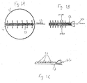
- the prior art is limited to distributing spent catalyst (11) through a main trough (12).
- the spent catalyst (11) proceeds along the main trough (12)
- the spent catalyst (11) flows over the walls of the main trough (12) in specified cutouts (13) of the main trough (12) (see also FIG. 8A ).
- This overflow is schematically represented by arrows.
- the spent catalyst (11) is distributed in a line across the catalyst bed (not pictured).
- the main trough (12) can be supported on the vessel wall (15) through a support means (16).
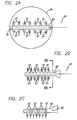
- the present invention improves upon the prior art by adding distribution troughs (21) along each side of the main trough (22).
- Each distribution trough (21) is angled downward from the main trough (22) so as to facilitate catalyst flow (see FIG. 8B ).
- Spent catalyst (23) therefore flows into the main trough (22) and, as the spent catalyst (23) proceeds along the main trough (22), portions are distributed to the catalyst bed (not pictured) via the distribution troughs (21) along the path of the arrows. Because the distribution troughs (21) extend out from the main trough (22) (see also FIG.
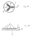
- FIGS. 3A and 3B depict another embodiment of the present invention that improves over the prior art by splitting the main trough (31) into sub-troughs (32).
- the term "sub-trough(s)” is not meant to indicate a trough that is smaller than the main trough (31).
- the term “sub-trough(s)” encompasses any trough (whether larger, smaller or equal in size) that branches off from the main trough (31).
- the spent catalyst (33) flows into and through the main trough (31). Portions of the spent catalyst (32) are distributed over the walls of the main trough (31) in specified cutouts (34) of the main trough (31) (see also FIG. 8A ). The arrows represent this overflow. Not all of the spent catalyst (33) is distributed through the cutouts (34), and remaining spent catalyst (33) is diverted into sub-troughs (32), which branch out from the main trough (31). The branches can begin at any point (35) along the main trough (31). As the spent catalyst (33) traverses the sub-troughs (32), portions of the spent catalyst (33) are distributed over the walls of the sub-troughs (32) in specified cutouts (34) of the sub-troughs (32).
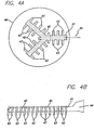
- FIGS. 4A and 4B embody yet another preferred embodiment of the present invention in which the improvement over the prior art is achieved by splitting a main trough (41) into sub-troughs (42). Furthermore, distribution troughs (43, only some are designated) line the sides of both the main trough (41) and sub-troughs (42) (see also FIG.
- the spent catalyst (44) flows into and through the main trough (41), and, as the spent catalyst (44) proceeds along the main trough (41), portions are distributed to the catalyst bed bottom (not pictured) via the distribution troughs (43) located on the main trough (41). Not all of the spent catalyst (44) is distributed through the main trough's (41) distribution troughs (43). Remaining spent catalyst (44) is then diverted into sub-troughs (42) which branch out from the main trough (41). The branches can begin at any point (45) along the main trough (41). Once spent catalyst (44) enters the sub-troughs (42), it is distributed to the catalyst bed (not pictured) via the distribution troughs (43) located on the main trough (41).
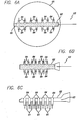
- FIGS. 5A, 5B and 5C embody yet another preferred embodiment of the present invention in which downflow tubes (51 in FIG. 5C and depicted as circles in FIG. 5A and FIG. 5B ) are provided in the middle of the main trough (52) (see also FIG. 8C ).
- FIG. 5C and depicted as circles in FIG. 5A and FIG. 5B ) extend from the bottom of the main trough (52), past the surface of the catalyst bed, and into the upper part of the catalyst bed (not shown). Because the spent catalyst (53) is distributed both above and below the catalyst bed surface (not shown), the spent catalyst (53) is distributed in a more even manner than in the prior art (see FIGS. 1A, 1B and 1C ). It is also envisioned that the main trough (52) can be supported on the vessel wall (55) via a support means (56).
- FIGS. 6A, 6B and 6C depict still yet another preferred embodiment of the present invention.
- downflow tubes (61 in FIG. 6C , not shown in FIGS. 6A or 6B ) are provided in the bottom of the main trough (62) and distribution troughs (64) along each side of the main trough (62).
- portions are distributed by the distribution troughs (64).
- Each distribution trough (64) is angled downward from the main trough (62) so as to facilitate catalyst flow.
- Spent catalyst (63) therefore flows into the main trough (62) and, as the spent catalyst (63) proceeds along the main trough (62), portions are distributed to the catalyst bed (not pictured) via the distribution troughs (64) along the path of the arrows. Not all of the spent catalyst (63) is distributed through the distribution troughs (64). A percentage of the spent catalyst (63) is distributed via the downflow tubes (61 in FIG. 6C , not shown in FIGS. 6A or 6B ). These downflow tubes (61 in FIG. 6C , not shown in FIGS. 6A or 6B ) extend from the bottom of the main trough (62) to below the surface of the catalyst bed (see FIG. 8C ). In a preferred embodiment, the downflow tubes (61 in FIG.
- FIGS. 6A or 6B extend from the bottom of the main trough (62), past the surface of the catalyst bed, and into the upper part of the catalyst bed (not shown). Because the distribution troughs (64) extend out from the main trough (62) (see also FIG. 8B ), and since some of the spent catalyst (63) is deposited beneath the surface of the catalyst bed, the spent catalyst (63) is distributed in a more even manner along and throughout the catalyst bed (not pictured) than in the prior art (see FIGS. 1A, 1B and 1C ). It is also envisioned that the main trough (62) can be supported on the vessel wall (65) via a support means (66).
- FIG. 7 shows another preferred embodiment of the present invention in which a main trough (71) is split into several sub-troughs (72). Furthermore, distribution troughs (73, only some are designated) line the sides of the sub-troughs (72) (see also FIG. 8B ). It is envisioned (but not shown) that distribution troughs (73) could also line the sides of the main trough (71).
- the spent catalyst (74) flows into and through the main trough (71), and, as the spent catalyst (74) proceeds along the main trough (71), portions of the spent catalyst (74) are distributed over the walls of the main trough (71) through cutouts (similar to FIG. 3B ) of the main trough (71). Not all of the spent catalyst (74) is distributed through the cutouts.
- the remaining spent catalyst (74) is then diverted into sub-troughs (72) which branch out from the main trough (71).
- the branches can begin at any point (75) along the main trough (71). It is envisioned that all branches can begin at the same or different points (75) along the main trough (71).
- spent catalyst (74) enters the sub-troughs (72), it is distributed to the catalyst bed (not pictured) via the distribution troughs (73) located on the sub-troughs (72). Because the distribution troughs (73) extend out from the sub-troughs (72) (see also FIG. 8B ), the spent catalyst (74) is distributed in a more even manner along the catalyst bed (not pictured) than in the prior art (see FIGS. 1A, 1B and 1C ). It is envisioned that the sub-troughs (72) can be supported on the vessel wall (76) through a support means (not shown).
- FIG. 8A shows a head-on point of view of a main trough (81) of the prior art along line 8A in FIG. 1A .
- spent catalyst flows through the main trough (81)
- spent catalyst flows over the walls of the main trough (81) at cutouts (82) in the direction of the arrows and is deposited on the catalyst bed below (not shown).
- FIG. 8B shows a head-on point of view of a main trough (81') in the present invention along line 8B in FIG. 2A .
- spent catalyst flows through the main trough (81')
- spent catalyst flows through the distribution troughs (83') in the direction of the arrows and is deposited on the catalyst bed below (not shown).
- FIG. 8C shows a head-on point of view of a main trough (81") in the present invention along line 8C in FIG. 5A .
- spent catalyst flows through the main trough (81")
- spent catalyst flows over the walls of the main trough (81") at cutouts (82") in the direction of the arrows and is deposited on the catalyst bed (84").
- Additional spent catalyst flows through the main trough, travels downward through the downflow tubes (85"), and is deposited below the surface of the catalyst bed (84").
- the spent catalyst is introduced into the regenerator from a catalytic cracking unit, although the present inventors contemplate that the invention may be employed in other applications that would benefit from improved distribution of particulate matter. It is envisioned that single stage, two-stage regenerators and side-by-side reactor/regenerator configurations can be utilized with the invention. Additional designs that may be forthcoming in the art can also be utilized with the invention.
- any number and combination of sub-troughs, distribution troughs, and/or downflow tubes can be utilized with the invention as long as an even manner of spent catalyst distribution is achieved. It is also envisioned that the spent catalyst can be aerated either from external sources or from captured flue gas inside the regenerator bed or unaerated in any manner known in the art as the need arises.
Landscapes
- Chemical & Material Sciences (AREA)
- Organic Chemistry (AREA)
- Chemical Kinetics & Catalysis (AREA)
- Engineering & Computer Science (AREA)
- Materials Engineering (AREA)
- Oil, Petroleum & Natural Gas (AREA)
- Combustion & Propulsion (AREA)
- General Chemical & Material Sciences (AREA)
- Devices And Processes Conducted In The Presence Of Fluids And Solid Particles (AREA)
- Feeding, Discharge, Calcimining, Fusing, And Gas-Generation Devices (AREA)
Claims (13)
- Verfahren zur Verteilung von verbrauchtem Katalysator in einem Katalysator-Regenerator für verbrauchten Katalysator für eine katalytische Fluid-Cracking-Einheit umfassend die folgenden Schritte:a. Sammeln von verbrauchtem Katalysator in einer Hauptwanne, und, gegebenenfalls, Fluidisieren und/oder Belüften des verbrauchten Katalysators;und eine oder mehrere der folgenden Gruppen von Schritten b.1 und c.1; b.2 und c.2; und b.3 und c.3:b.1 Weiterleiten des verbrauchten Katalysators aus der Hauptwanne zu einer Mehrzahl von entlang einer jeden Seite der Hauptwanne angeordneten Verteilungswannen; undc.1 Einführen des verbrauchten Katalysators aus der Mehrzahl von Verteilungswannen in ein Katalysatorbett;b.2 Weiterleiten eines Protzentsatzes des verbrauchten Katalysators aus der Hauptwanne zu einer Mehrzahl von Nebenwannen; undc.2 Einführen des verbrauchten Katalysators aus der Mehrzahl von Nebenwannen und aus der Hauptwanne in ein Katalysatorbett;b.3 Weiterleiten eines Protzentsatzes des verbrauchten Katalysators aus der Hauptwanne zu einer Mehrzahl von am Boden der Hauptwanne angeordneten Abwärtsstromrohren;c.3 Einführen des in der Hauptwanne verbleibenden verbrauchten Katalysators in ein Katalysatorbett über mindestens eines, ausgewählt aus der Gruppe bestehend aus einer Mehrzahl von entlang den Wänden der Hauptwanne angeordneten Aussparungen und einer Mehrzahl von an den Seiten der Hauptwanne angeordneten Verteilungswannen und Einführen des verbrauchten Katalysators in die Mehrzahl von Abwärtsstromrohren in das Katalysatorbett.
- Verfahren nach Anspruch 1, wobei der verbrauchte Katalysator aus der Hauptwanne und der Mehrzahl von Nebenwannen über eine Mehrzahl von an den Wänden der Hauptwanne angeordneten Aussparungen und die Mehrzahl von Nebenwannen in ein Katalysatorbett eingeleitet wird.
- Verfahren nach Anspruch 1, wobei der verbrauchte Katalysator aus der Hauptwanne und der Mehrzahl von Nebenwannen über eine Mehrzahl von an den Seiten der Hauptwanne angeordneten Verteilungswannen und die Mehrzahl von Nebenwannen in das Katalysatorbett eingeleitet wird.
- Verfahren nach Anspruch 1, wobei eine Mehrzahl von Abwärtsstromrohren mit dem Boden der Hauptwanne verbunden ist, und weiterhin umfassend die Schritte- Weiterleiten von etwas verbrauchtem Katalysator zu der Mehrzahl von Abwärtsstromrohren; und- Einführen des verbrauchten Katalysators in die Mehrzahl von Abwärtsstromrohren in das Katalysatorbett.
- Verfahren nach Anspruch 3, wobei eine Mehrzahl von Abwärtsstromrohren mit dem Boden von mindestens einem, ausgewählt aus der Gruppe bestehend aus der Hauptwanne und der Mehrzahl von Nebenwannen, verbunden ist, und weiterhin umfassend die folgenden Schritte:- Weiterleiten von etwas verbrauchtem Katalysator in die Mehrzahl von Abwärtsstromrohren; und- Einführen des verbrauchten Katalysators in die Mehrzahl von Abwärtsstromrohren in das Katalysatorbett.
- Verfahren nach Ansprüchen 1,4 oder 5, wobei sich mindestens eines aus der Mehrzahl von Abwärtsstromrohren unter die Oberfläche des Katalysatorbetts erstreckt, und der verbrauchte Katalysator, der durch die Abwärtsstromrohre nach unten wandert, unter der Oberfläche des Katalysatorbetts abgelagert wird.
- Verfahren nach Anspruch 6, wobei sich mindestens eines der Abwärtsstromrohre unter die Oberfläche des Katalysatorbetts und in den oberen Teil des Katalysatorbetts hinein erstreckt, und der verbrauchte Katalysator, der durch die Abwärtsstromrohre nach unten wandert, im oberen Teil des Katalysatorbetts abgelagert wird.
- Verfahren nach den Ansprüchen 1 oder 3, wobei mindestens eine aus der Mehrzahl von Verteilungswannen nach unten gerichtet ist.
- Verfahren nach Anspruch 1, wobei Schritt a. folgender ist:a. Sammeln von verbrauchtem Katalysator in einer Hauptwanne und, gegebenenfalls, Fluidisieren und/oder Belüften des verbrauchten Katalysators mit von außen zugeführtem Medium oder unter Verwendung von unter einer Wanne eingefangenem Rauchgas.
- Verteiler für verbrauchten Katalysator zur Unterstützung bei der Regeneration von verbrauchtem Katalysator in einer katalytischen Fluid-Cracking-Einheit, umfassend:a. eine Hauptwanne; undb. ein oder zwei oder drei Elemente aus der Gruppe bestehend aus:i. eine Mehrzahl von Verteilungswannen, die sich von den Seiten der Hauptwanne nach außen erstrecken;ii. eine Mehrzahl von Nebenwannen, die von der Hauptwanne abzweigen; undiii. eine Mehrzahl von Abwärtsstromrohren, die mit dem Boden der Hauptwanne verbunden sind.
- Verteiler für verbrauchten Katalysator nach Anspruch 10, wobei eine zweite Mehrzahl von Abwärtsstromrohren mit dem Boden von mindestens einer aus der Mehrzahl von Nebenwannen verbunden ist.
- Verteiler für verbrauchten Katalysator nach Anspruch 10, wobei sich eine zweite Mehrzahl von Verteilungswannen von den Seiten von mindestens einer der Nebenwannen nach außen erstreckt.
- Verteiler für verbrauchten Katalysator nach Anspruch 10 oder 12, wobei mindestens eine aus der Mehrzahl von Verteilungswannen und/oder mindestens eine der zweiten Mehrzahl von Verteilungswannen nach unten gerichtet ist.
Applications Claiming Priority (1)
| Application Number | Priority Date | Filing Date | Title |
|---|---|---|---|
| US11/716,350 US7745365B2 (en) | 2007-03-09 | 2007-03-09 | Bathtub-type spent catalyst distributor for effective counter-current regeneration in fluid catalytic cracking units |
Publications (2)
| Publication Number | Publication Date |
|---|---|
| EP1967259A1 EP1967259A1 (de) | 2008-09-10 |
| EP1967259B1 true EP1967259B1 (de) | 2018-01-17 |
Family
ID=39493478
Family Applications (1)
| Application Number | Title | Priority Date | Filing Date |
|---|---|---|---|
| EP08003653.6A Active EP1967259B1 (de) | 2007-03-09 | 2008-02-28 | Verfahren zur Verteilung von verbrauchtem Katalysator in einem Katalysator-Regenerator einer katalytischen Fluid-Cracking-Einheit |
Country Status (9)
| Country | Link |
|---|---|
| US (3) | US7745365B2 (de) |
| EP (1) | EP1967259B1 (de) |
| JP (1) | JP4942683B2 (de) |
| KR (1) | KR101482586B1 (de) |
| CA (1) | CA2623789A1 (de) |
| EA (1) | EA013040B1 (de) |
| MX (1) | MX2008003221A (de) |
| MY (1) | MY153185A (de) |
| SG (2) | SG165320A1 (de) |
Families Citing this family (8)
| Publication number | Priority date | Publication date | Assignee | Title |
|---|---|---|---|---|
| US8728302B2 (en) | 2010-06-25 | 2014-05-20 | Exxonmobil Research And Engineering Company | Spent catalyst riser distributor |
| EP3389865B1 (de) * | 2015-12-18 | 2025-02-19 | Uop Llc | Hocheffizienter fcc-regenerator mit hocheffizienter partieller verbrennung |
| CN108246368B (zh) * | 2016-12-28 | 2020-11-13 | 中国石化工程建设有限公司 | 热膨胀自协调式主风分布器 |
| EP3409348B1 (de) * | 2017-06-03 | 2020-07-22 | INDIAN OIL CORPORATION Ltd. | Vorrichtung zur verteilung eines katalysators in einer katalytischen fliessbett-crackanlage |
| CN107628986B (zh) * | 2017-10-20 | 2021-07-13 | 山东明化新材料有限公司 | 一种吡啶生产用的催化剂均布器 |
| EP3939697B1 (de) | 2019-03-18 | 2023-08-02 | Shanghai Supezet Engineering Technology Co., Ltd. | Vorrichtung für katalytische alkandehydrierungsreaktion mit ringförmigem katalysatorverteiler |
| CN111715153B (zh) * | 2019-03-18 | 2022-08-05 | 江苏博颂化工科技有限公司 | 烷烃脱氢循环流化床反应装置 |
| US11266923B2 (en) | 2019-04-24 | 2022-03-08 | Technip Process Technology, Inc. | Fluid distribution devices |
Family Cites Families (11)
| Publication number | Priority date | Publication date | Assignee | Title |
|---|---|---|---|---|
| US2548285A (en) * | 1947-08-15 | 1951-04-10 | Socony Vacuum Oil Co Inc | Method and apparatus for hydrocarbon conversion |
| DE2707478A1 (de) * | 1976-03-01 | 1977-09-08 | Pullman Inc | Verfahren und vorrichtung zur regenerierung von crack-katalysatoren |
| US5156817A (en) * | 1990-05-15 | 1992-10-20 | Exxon Research And Engineering Company | Fccu regenerator catalyst distribution system |
| TW351683B (en) * | 1993-04-21 | 1999-02-01 | Shell Int Research | Process for radially distributing a dispersion of particles in a fluid into a mass of particles dispersed in a fluid |
| US5635140A (en) * | 1995-11-13 | 1997-06-03 | The M. W. Kellogg Company | Self-aerating spent catalyst distributor |
| US5773378A (en) * | 1996-10-30 | 1998-06-30 | The M. W. Kellogg Company | Spent catalyst distribution |
| US6809054B1 (en) * | 2000-11-21 | 2004-10-26 | Uop Llc | FCC spent catalyst distributor |
| US6797239B1 (en) * | 2000-11-22 | 2004-09-28 | Shell Oil Company | Spent catalyst distributor |
| US7153479B2 (en) * | 2002-10-10 | 2006-12-26 | Kellogg Brown & Root Llc | Catalyst regenerator with a centerwell |
| US6971633B2 (en) * | 2002-10-15 | 2005-12-06 | Banjo Corporation | Rotatable seal for ball valve |
| CN1208433C (zh) | 2003-09-02 | 2005-06-29 | 中国石油化工集团公司 | 流化催化裂化装置待生催化剂分配器 |
-
2007
- 2007-03-09 US US11/716,350 patent/US7745365B2/en active Active
-
2008
- 2008-01-30 EA EA200800192A patent/EA013040B1/ru active IP Right Revival
- 2008-02-22 JP JP2008041338A patent/JP4942683B2/ja active Active
- 2008-02-25 MY MYPI20080406A patent/MY153185A/en unknown
- 2008-02-27 SG SG201006250-3A patent/SG165320A1/en unknown
- 2008-02-27 SG SG200801630-5A patent/SG146533A1/en unknown
- 2008-02-28 EP EP08003653.6A patent/EP1967259B1/de active Active
- 2008-03-03 CA CA 2623789 patent/CA2623789A1/en not_active Abandoned
- 2008-03-07 KR KR1020080021367A patent/KR101482586B1/ko active Active
- 2008-03-07 MX MX2008003221A patent/MX2008003221A/es active IP Right Grant
-
2010
- 2010-02-18 US US12/707,836 patent/US7951739B2/en active Active
-
2011
- 2011-03-23 US US13/069,867 patent/US8349753B2/en active Active
Non-Patent Citations (1)
| Title |
|---|
| None * |
Also Published As
| Publication number | Publication date |
|---|---|
| US8349753B2 (en) | 2013-01-08 |
| KR20080082923A (ko) | 2008-09-12 |
| MY153185A (en) | 2015-01-29 |
| US20100147412A1 (en) | 2010-06-17 |
| US20080220965A1 (en) | 2008-09-11 |
| MX2008003221A (es) | 2009-02-25 |
| EA200800192A1 (ru) | 2008-10-30 |
| US7745365B2 (en) | 2010-06-29 |
| JP4942683B2 (ja) | 2012-05-30 |
| EP1967259A1 (de) | 2008-09-10 |
| SG165320A1 (en) | 2010-10-28 |
| KR101482586B1 (ko) | 2015-01-14 |
| US7951739B2 (en) | 2011-05-31 |
| SG146533A1 (en) | 2008-10-30 |
| EA013040B1 (ru) | 2010-02-26 |
| JP2008221210A (ja) | 2008-09-25 |
| US20110200459A1 (en) | 2011-08-18 |
| CA2623789A1 (en) | 2008-09-09 |
Similar Documents
| Publication | Publication Date | Title |
|---|---|---|
| US8349753B2 (en) | Bathtub-type spent catalyst distributor for effective counter-current regeneration in fluid catalytic cracking units | |
| US7368090B2 (en) | FCC spent catalyst distributor | |
| US7026262B1 (en) | Apparatus and process for regenerating catalyst | |
| US4150090A (en) | Apparatus for regeneration of cracking catalyst | |
| AU2002310390B2 (en) | Stripping apparatus | |
| US6797239B1 (en) | Spent catalyst distributor | |
| US7947230B2 (en) | Apparatus for regenerating catalyst | |
| HU218365B (hu) | Eljárás és berendezés fluidizált szilárd anyagok sztrippelésére | |
| AU2002229564A1 (en) | Spent Catalyst Distributor | |
| CA2121670C (en) | Process and apparatus for distributing fluids in a container | |
| CN102316985A (zh) | 用于再生催化剂的设备 | |
| US5015363A (en) | FCC stripping method | |
| EP2520856A1 (de) | Hocheffiziente verbrennungsvorrichtung und katalytisches fliessbett-cracking-verfahren zur herstellung leichter olefine | |
| US4994424A (en) | Catalytic cracking process with improved flow in swirl regenerator | |
| ES3009762T3 (en) | Fcc high efficiency partial burn regenerator | |
| US4927606A (en) | FCC Stripping apparatus | |
| US20120053047A1 (en) | Method for Drying Regenerated Catalyst in Route to a Propane Dehydrogenation Reactor | |
| JP7117105B2 (ja) | 流動固体分配装置 | |
| KR20240027031A (ko) | 플레이트 그리드 분배기를 갖는 화학적 처리 용기 및 이를 작동하는 방법 | |
| US8603406B2 (en) | For drying regenerated catalyst in route to a propane dehydrogenation reactor | |
| CA1095876A (en) | Method and apparatus for regeneration of cracking catalyst | |
| JPH0643585B2 (ja) | ストリッピングガス注入口を有する邪魔板スカート付き端から端まで型fccストリッピング装置 | |
| JPS6026579B2 (ja) | 二重シエル流動層反応塔 |
Legal Events
| Date | Code | Title | Description |
|---|---|---|---|
| PUAI | Public reference made under article 153(3) epc to a published international application that has entered the european phase |
Free format text: ORIGINAL CODE: 0009012 |
|
| AK | Designated contracting states |
Kind code of ref document: A1 Designated state(s): AT BE BG CH CY CZ DE DK EE ES FI FR GB GR HR HU IE IS IT LI LT LU LV MC MT NL NO PL PT RO SE SI SK TR |
|
| AX | Request for extension of the european patent |
Extension state: AL BA MK RS |
|
| 17P | Request for examination filed |
Effective date: 20090209 |
|
| 17Q | First examination report despatched |
Effective date: 20090306 |
|
| AKX | Designation fees paid |
Designated state(s): AT BE BG CH CY CZ DE DK EE ES FI FR GB GR HR HU IE IS IT LI LT LU LV MC MT NL NO PL PT RO SE SI SK TR |
|
| AXX | Extension fees paid |
Extension state: RS Payment date: 20090209 |
|
| RAP1 | Party data changed (applicant data changed or rights of an application transferred) |
Owner name: TECHNIP PROCESS TECHNOLOGY, INC. |
|
| GRAP | Despatch of communication of intention to grant a patent |
Free format text: ORIGINAL CODE: EPIDOSNIGR1 |
|
| STAA | Information on the status of an ep patent application or granted ep patent |
Free format text: STATUS: GRANT OF PATENT IS INTENDED |
|
| INTG | Intention to grant announced |
Effective date: 20170726 |
|
| GRAS | Grant fee paid |
Free format text: ORIGINAL CODE: EPIDOSNIGR3 |
|
| GRAA | (expected) grant |
Free format text: ORIGINAL CODE: 0009210 |
|
| STAA | Information on the status of an ep patent application or granted ep patent |
Free format text: STATUS: THE PATENT HAS BEEN GRANTED |
|
| RAP1 | Party data changed (applicant data changed or rights of an application transferred) |
Owner name: TECHNIP PROCESS TECHNOLOGY, INC. |
|
| AK | Designated contracting states |
Kind code of ref document: B1 Designated state(s): AT BE BG CH CY CZ DE DK EE ES FI FR GB GR HR HU IE IS IT LI LT LU LV MC MT NL NO PL PT RO SE SI SK TR |
|
| AX | Request for extension of the european patent |
Extension state: RS |
|
| REG | Reference to a national code |
Ref country code: GB Ref legal event code: FG4D |
|
| REG | Reference to a national code |
Ref country code: CH Ref legal event code: EP |
|
| REG | Reference to a national code |
Ref country code: IE Ref legal event code: FG4D |
|
| REG | Reference to a national code |
Ref country code: AT Ref legal event code: REF Ref document number: 964038 Country of ref document: AT Kind code of ref document: T Effective date: 20180215 |
|
| REG | Reference to a national code |
Ref country code: DE Ref legal event code: R096 Ref document number: 602008053758 Country of ref document: DE Ref country code: FR Ref legal event code: PLFP Year of fee payment: 11 |
|
| REG | Reference to a national code |
Ref country code: NL Ref legal event code: FP |
|
| REG | Reference to a national code |
Ref country code: LT Ref legal event code: MG4D |
|
| REG | Reference to a national code |
Ref country code: AT Ref legal event code: MK05 Ref document number: 964038 Country of ref document: AT Kind code of ref document: T Effective date: 20180117 |
|
| PG25 | Lapsed in a contracting state [announced via postgrant information from national office to epo] |
Ref country code: ES Free format text: LAPSE BECAUSE OF FAILURE TO SUBMIT A TRANSLATION OF THE DESCRIPTION OR TO PAY THE FEE WITHIN THE PRESCRIBED TIME-LIMIT Effective date: 20180117 Ref country code: LT Free format text: LAPSE BECAUSE OF FAILURE TO SUBMIT A TRANSLATION OF THE DESCRIPTION OR TO PAY THE FEE WITHIN THE PRESCRIBED TIME-LIMIT Effective date: 20180117 Ref country code: CY Free format text: LAPSE BECAUSE OF FAILURE TO SUBMIT A TRANSLATION OF THE DESCRIPTION OR TO PAY THE FEE WITHIN THE PRESCRIBED TIME-LIMIT Effective date: 20180117 Ref country code: FI Free format text: LAPSE BECAUSE OF FAILURE TO SUBMIT A TRANSLATION OF THE DESCRIPTION OR TO PAY THE FEE WITHIN THE PRESCRIBED TIME-LIMIT Effective date: 20180117 Ref country code: HR Free format text: LAPSE BECAUSE OF FAILURE TO SUBMIT A TRANSLATION OF THE DESCRIPTION OR TO PAY THE FEE WITHIN THE PRESCRIBED TIME-LIMIT Effective date: 20180117 Ref country code: NO Free format text: LAPSE BECAUSE OF FAILURE TO SUBMIT A TRANSLATION OF THE DESCRIPTION OR TO PAY THE FEE WITHIN THE PRESCRIBED TIME-LIMIT Effective date: 20180417 |
|
| PG25 | Lapsed in a contracting state [announced via postgrant information from national office to epo] |
Ref country code: AT Free format text: LAPSE BECAUSE OF FAILURE TO SUBMIT A TRANSLATION OF THE DESCRIPTION OR TO PAY THE FEE WITHIN THE PRESCRIBED TIME-LIMIT Effective date: 20180117 Ref country code: GR Free format text: LAPSE BECAUSE OF FAILURE TO SUBMIT A TRANSLATION OF THE DESCRIPTION OR TO PAY THE FEE WITHIN THE PRESCRIBED TIME-LIMIT Effective date: 20180418 Ref country code: BG Free format text: LAPSE BECAUSE OF FAILURE TO SUBMIT A TRANSLATION OF THE DESCRIPTION OR TO PAY THE FEE WITHIN THE PRESCRIBED TIME-LIMIT Effective date: 20180417 Ref country code: PL Free format text: LAPSE BECAUSE OF FAILURE TO SUBMIT A TRANSLATION OF THE DESCRIPTION OR TO PAY THE FEE WITHIN THE PRESCRIBED TIME-LIMIT Effective date: 20180117 Ref country code: LV Free format text: LAPSE BECAUSE OF FAILURE TO SUBMIT A TRANSLATION OF THE DESCRIPTION OR TO PAY THE FEE WITHIN THE PRESCRIBED TIME-LIMIT Effective date: 20180117 Ref country code: SE Free format text: LAPSE BECAUSE OF FAILURE TO SUBMIT A TRANSLATION OF THE DESCRIPTION OR TO PAY THE FEE WITHIN THE PRESCRIBED TIME-LIMIT Effective date: 20180117 Ref country code: IS Free format text: LAPSE BECAUSE OF FAILURE TO SUBMIT A TRANSLATION OF THE DESCRIPTION OR TO PAY THE FEE WITHIN THE PRESCRIBED TIME-LIMIT Effective date: 20180517 |
|
| REG | Reference to a national code |
Ref country code: CH Ref legal event code: PL |
|
| REG | Reference to a national code |
Ref country code: DE Ref legal event code: R097 Ref document number: 602008053758 Country of ref document: DE |
|
| PG25 | Lapsed in a contracting state [announced via postgrant information from national office to epo] |
Ref country code: RO Free format text: LAPSE BECAUSE OF FAILURE TO SUBMIT A TRANSLATION OF THE DESCRIPTION OR TO PAY THE FEE WITHIN THE PRESCRIBED TIME-LIMIT Effective date: 20180117 Ref country code: MC Free format text: LAPSE BECAUSE OF FAILURE TO SUBMIT A TRANSLATION OF THE DESCRIPTION OR TO PAY THE FEE WITHIN THE PRESCRIBED TIME-LIMIT Effective date: 20180117 Ref country code: EE Free format text: LAPSE BECAUSE OF FAILURE TO SUBMIT A TRANSLATION OF THE DESCRIPTION OR TO PAY THE FEE WITHIN THE PRESCRIBED TIME-LIMIT Effective date: 20180117 |
|
| PLBE | No opposition filed within time limit |
Free format text: ORIGINAL CODE: 0009261 |
|
| STAA | Information on the status of an ep patent application or granted ep patent |
Free format text: STATUS: NO OPPOSITION FILED WITHIN TIME LIMIT |
|
| REG | Reference to a national code |
Ref country code: IE Ref legal event code: MM4A |
|
| PG25 | Lapsed in a contracting state [announced via postgrant information from national office to epo] |
Ref country code: LU Free format text: LAPSE BECAUSE OF NON-PAYMENT OF DUE FEES Effective date: 20180228 Ref country code: DK Free format text: LAPSE BECAUSE OF FAILURE TO SUBMIT A TRANSLATION OF THE DESCRIPTION OR TO PAY THE FEE WITHIN THE PRESCRIBED TIME-LIMIT Effective date: 20180117 Ref country code: CZ Free format text: LAPSE BECAUSE OF FAILURE TO SUBMIT A TRANSLATION OF THE DESCRIPTION OR TO PAY THE FEE WITHIN THE PRESCRIBED TIME-LIMIT Effective date: 20180117 Ref country code: SK Free format text: LAPSE BECAUSE OF FAILURE TO SUBMIT A TRANSLATION OF THE DESCRIPTION OR TO PAY THE FEE WITHIN THE PRESCRIBED TIME-LIMIT Effective date: 20180117 Ref country code: LI Free format text: LAPSE BECAUSE OF NON-PAYMENT OF DUE FEES Effective date: 20180228 Ref country code: CH Free format text: LAPSE BECAUSE OF NON-PAYMENT OF DUE FEES Effective date: 20180228 |
|
| 26N | No opposition filed |
Effective date: 20181018 |
|
| PG25 | Lapsed in a contracting state [announced via postgrant information from national office to epo] |
Ref country code: IE Free format text: LAPSE BECAUSE OF NON-PAYMENT OF DUE FEES Effective date: 20180228 |
|
| PG25 | Lapsed in a contracting state [announced via postgrant information from national office to epo] |
Ref country code: SI Free format text: LAPSE BECAUSE OF FAILURE TO SUBMIT A TRANSLATION OF THE DESCRIPTION OR TO PAY THE FEE WITHIN THE PRESCRIBED TIME-LIMIT Effective date: 20180117 |
|
| PG25 | Lapsed in a contracting state [announced via postgrant information from national office to epo] |
Ref country code: MT Free format text: LAPSE BECAUSE OF NON-PAYMENT OF DUE FEES Effective date: 20180228 |
|
| PG25 | Lapsed in a contracting state [announced via postgrant information from national office to epo] |
Ref country code: TR Free format text: LAPSE BECAUSE OF FAILURE TO SUBMIT A TRANSLATION OF THE DESCRIPTION OR TO PAY THE FEE WITHIN THE PRESCRIBED TIME-LIMIT Effective date: 20180117 |
|
| PG25 | Lapsed in a contracting state [announced via postgrant information from national office to epo] |
Ref country code: PT Free format text: LAPSE BECAUSE OF FAILURE TO SUBMIT A TRANSLATION OF THE DESCRIPTION OR TO PAY THE FEE WITHIN THE PRESCRIBED TIME-LIMIT Effective date: 20180117 Ref country code: HU Free format text: LAPSE BECAUSE OF FAILURE TO SUBMIT A TRANSLATION OF THE DESCRIPTION OR TO PAY THE FEE WITHIN THE PRESCRIBED TIME-LIMIT; INVALID AB INITIO Effective date: 20080228 |
|
| P01 | Opt-out of the competence of the unified patent court (upc) registered |
Effective date: 20230601 |
|
| PGFP | Annual fee paid to national office [announced via postgrant information from national office to epo] |
Ref country code: NL Payment date: 20260128 Year of fee payment: 19 |
|
| PGFP | Annual fee paid to national office [announced via postgrant information from national office to epo] |
Ref country code: GB Payment date: 20260128 Year of fee payment: 19 |
|
| PGFP | Annual fee paid to national office [announced via postgrant information from national office to epo] |
Ref country code: DE Payment date: 20260121 Year of fee payment: 19 |
|
| PGFP | Annual fee paid to national office [announced via postgrant information from national office to epo] |
Ref country code: BE Payment date: 20260122 Year of fee payment: 19 Ref country code: IT Payment date: 20260128 Year of fee payment: 19 |
|
| PGFP | Annual fee paid to national office [announced via postgrant information from national office to epo] |
Ref country code: FR Payment date: 20260121 Year of fee payment: 19 |