EP3409348B1 - Vorrichtung zur verteilung eines katalysators in einer katalytischen fliessbett-crackanlage - Google Patents
Vorrichtung zur verteilung eines katalysators in einer katalytischen fliessbett-crackanlage Download PDFInfo
- Publication number
- EP3409348B1 EP3409348B1 EP18161020.5A EP18161020A EP3409348B1 EP 3409348 B1 EP3409348 B1 EP 3409348B1 EP 18161020 A EP18161020 A EP 18161020A EP 3409348 B1 EP3409348 B1 EP 3409348B1
- Authority
- EP
- European Patent Office
- Prior art keywords
- catalyst
- conduit
- regenerator
- spent catalyst
- orifices
- Prior art date
- Legal status (The legal status is an assumption and is not a legal conclusion. Google has not performed a legal analysis and makes no representation as to the accuracy of the status listed.)
- Active
Links
- 0 CC1(C(CCCCC*)C*2CCCCC2)C(C2)(CC3)C=C(CCC*)C2C3CCC1 Chemical compound CC1(C(CCCCC*)C*2CCCCC2)C(C2)(CC3)C=C(CCC*)C2C3CCC1 0.000 description 2
Images






Classifications
-
- B—PERFORMING OPERATIONS; TRANSPORTING
- B01—PHYSICAL OR CHEMICAL PROCESSES OR APPARATUS IN GENERAL
- B01J—CHEMICAL OR PHYSICAL PROCESSES, e.g. CATALYSIS OR COLLOID CHEMISTRY; THEIR RELEVANT APPARATUS
- B01J38/00—Regeneration or reactivation of catalysts, in general
- B01J38/04—Gas or vapour treating; Treating by using liquids vaporisable upon contacting spent catalyst
- B01J38/12—Treating with free oxygen-containing gas
- B01J38/30—Treating with free oxygen-containing gas in gaseous suspension, e.g. fluidised bed
-
- B—PERFORMING OPERATIONS; TRANSPORTING
- B01—PHYSICAL OR CHEMICAL PROCESSES OR APPARATUS IN GENERAL
- B01J—CHEMICAL OR PHYSICAL PROCESSES, e.g. CATALYSIS OR COLLOID CHEMISTRY; THEIR RELEVANT APPARATUS
- B01J8/00—Chemical or physical processes in general, conducted in the presence of fluids and solid particles; Apparatus for such processes
- B01J8/18—Chemical or physical processes in general, conducted in the presence of fluids and solid particles; Apparatus for such processes with fluidised particles
- B01J8/24—Chemical or physical processes in general, conducted in the presence of fluids and solid particles; Apparatus for such processes with fluidised particles according to "fluidised-bed" technique
- B01J8/26—Chemical or physical processes in general, conducted in the presence of fluids and solid particles; Apparatus for such processes with fluidised particles according to "fluidised-bed" technique with two or more fluidised beds, e.g. reactor and regeneration installations
-
- B—PERFORMING OPERATIONS; TRANSPORTING
- B01—PHYSICAL OR CHEMICAL PROCESSES OR APPARATUS IN GENERAL
- B01J—CHEMICAL OR PHYSICAL PROCESSES, e.g. CATALYSIS OR COLLOID CHEMISTRY; THEIR RELEVANT APPARATUS
- B01J8/00—Chemical or physical processes in general, conducted in the presence of fluids and solid particles; Apparatus for such processes
- B01J8/0015—Feeding of the particles in the reactor; Evacuation of the particles out of the reactor
- B01J8/0025—Feeding of the particles in the reactor; Evacuation of the particles out of the reactor by an ascending fluid
-
- B—PERFORMING OPERATIONS; TRANSPORTING
- B01—PHYSICAL OR CHEMICAL PROCESSES OR APPARATUS IN GENERAL
- B01J—CHEMICAL OR PHYSICAL PROCESSES, e.g. CATALYSIS OR COLLOID CHEMISTRY; THEIR RELEVANT APPARATUS
- B01J8/00—Chemical or physical processes in general, conducted in the presence of fluids and solid particles; Apparatus for such processes
- B01J8/0015—Feeding of the particles in the reactor; Evacuation of the particles out of the reactor
- B01J8/003—Feeding of the particles in the reactor; Evacuation of the particles out of the reactor in a downward flow
-
- B—PERFORMING OPERATIONS; TRANSPORTING
- B01—PHYSICAL OR CHEMICAL PROCESSES OR APPARATUS IN GENERAL
- B01J—CHEMICAL OR PHYSICAL PROCESSES, e.g. CATALYSIS OR COLLOID CHEMISTRY; THEIR RELEVANT APPARATUS
- B01J8/00—Chemical or physical processes in general, conducted in the presence of fluids and solid particles; Apparatus for such processes
- B01J8/0015—Feeding of the particles in the reactor; Evacuation of the particles out of the reactor
- B01J8/004—Feeding of the particles in the reactor; Evacuation of the particles out of the reactor by means of a nozzle
-
- B—PERFORMING OPERATIONS; TRANSPORTING
- B01—PHYSICAL OR CHEMICAL PROCESSES OR APPARATUS IN GENERAL
- B01J—CHEMICAL OR PHYSICAL PROCESSES, e.g. CATALYSIS OR COLLOID CHEMISTRY; THEIR RELEVANT APPARATUS
- B01J8/00—Chemical or physical processes in general, conducted in the presence of fluids and solid particles; Apparatus for such processes
- B01J8/18—Chemical or physical processes in general, conducted in the presence of fluids and solid particles; Apparatus for such processes with fluidised particles
- B01J8/1818—Feeding of the fluidising gas
-
- C—CHEMISTRY; METALLURGY
- C10—PETROLEUM, GAS OR COKE INDUSTRIES; TECHNICAL GASES CONTAINING CARBON MONOXIDE; FUELS; LUBRICANTS; PEAT
- C10G—CRACKING HYDROCARBON OILS; PRODUCTION OF LIQUID HYDROCARBON MIXTURES, e.g. BY DESTRUCTIVE HYDROGENATION, OLIGOMERISATION, POLYMERISATION; RECOVERY OF HYDROCARBON OILS FROM OIL-SHALE, OIL-SAND, OR GASES; REFINING MIXTURES MAINLY CONSISTING OF HYDROCARBONS; REFORMING OF NAPHTHA; MINERAL WAXES
- C10G11/00—Catalytic cracking, in the absence of hydrogen, of hydrocarbon oils
- C10G11/14—Catalytic cracking, in the absence of hydrogen, of hydrocarbon oils with preheated moving solid catalysts
- C10G11/18—Catalytic cracking, in the absence of hydrogen, of hydrocarbon oils with preheated moving solid catalysts according to the "fluidised-bed" technique
- C10G11/182—Regeneration
-
- B—PERFORMING OPERATIONS; TRANSPORTING
- B01—PHYSICAL OR CHEMICAL PROCESSES OR APPARATUS IN GENERAL
- B01J—CHEMICAL OR PHYSICAL PROCESSES, e.g. CATALYSIS OR COLLOID CHEMISTRY; THEIR RELEVANT APPARATUS
- B01J8/00—Chemical or physical processes in general, conducted in the presence of fluids and solid particles; Apparatus for such processes
- B01J8/18—Chemical or physical processes in general, conducted in the presence of fluids and solid particles; Apparatus for such processes with fluidised particles
- B01J8/1809—Controlling processes
-
- C—CHEMISTRY; METALLURGY
- C10—PETROLEUM, GAS OR COKE INDUSTRIES; TECHNICAL GASES CONTAINING CARBON MONOXIDE; FUELS; LUBRICANTS; PEAT
- C10G—CRACKING HYDROCARBON OILS; PRODUCTION OF LIQUID HYDROCARBON MIXTURES, e.g. BY DESTRUCTIVE HYDROGENATION, OLIGOMERISATION, POLYMERISATION; RECOVERY OF HYDROCARBON OILS FROM OIL-SHALE, OIL-SAND, OR GASES; REFINING MIXTURES MAINLY CONSISTING OF HYDROCARBONS; REFORMING OF NAPHTHA; MINERAL WAXES
- C10G2300/00—Aspects relating to hydrocarbon processing covered by groups C10G1/00 - C10G99/00
- C10G2300/70—Catalyst aspects
Definitions
- the present subject matter relates to a catalyst regenerator comprising a spent catalyst distributor for distributing spent catalyst.
- Spent catalyst distributors are known for many years.
- FCC Fluidized Catalytic Cracking
- the catalyst comes in contact with atomized heavy hydrocarbon molecules in the riser.
- the riser at high temperature, cracking occurs and coke gets deposited on the catalyst.
- the catalyst enters into stripper for removing the entrapped hydrocarbons inside the catalyst pores.
- the coke laden catalyst leaving the stripper is hereby being referred as "spent catalyst".
- the coke on the spent catalyst which covers the active sites on the catalyst and thereby substantially reduces the activity of the catalyst. It is possible, however, to remove the coke from the catalyst inside the regenerator by burning with air.
- the spent catalyst is fed into the regenerator through a "Spent Catalyst Distributor" (SCD) for uniform burning of the catalyst inside the Regenerator.
- SCD Spent Catalyst Distributor
- the coke deposited on the catalyst gets converted into CO, CO2.
- the regenerated catalyst with significantly lesser coke content is again being circulated to riser for cracking.
- US5773378 discloses a device to distribute spent catalyst at the lower end of a spent catalyst standpipe.
- the standpipe enters the regenerator from the side wall, near the top of the bed level, conveying the catalyst through a horizontal conduit to the center of the regenerator, followed by a vertically downward conduit with a deflector plate end cap, and discharging catalyst through a plurality of discrete radial slots on the lower side wall of the vertical conduit.
- US5635140 covers a self-aerating spent catalyst distributor to discharge catalyst radially and downwardly from a center-well via lipped trough arms into the catalyst bed.
- US6503460 describes a FCC regenerator countercurrent equipped with an internal baffle separating the dense phase of the fluidized bed in two parts. While the primary objective of the baffle is to reduce back mixing between the upper and lower sections of the fluidized bed. The baffles also facilitate the reduction in the diameter of the rising bubbles of gas passing through the dense bed, just before bursting at the surface of dense catalyst bed. This leads to reduction in the entrainment of catalyst.
- US6809054 discloses a design of SCD distributor arrangement for introducing spent fluid catalytic cracking catalyst more uniformly across the dense bed of a regenerator to provide more even contact with regeneration gas in order to avoid hot spots and zones of incomplete combustion.
- a spent catalyst carrying arm extends out from the wall of the regenerator and extends towards the opposite wall.
- This invention also considers the use of aeration flow to fluidize the extended arm to assist catalyst flow.
- This patent also teaches that small arms can extend from the main arm at angles of 90° or 60°.
- this design while not in the shape of a spooked wheel, also causes the catalyst to be distributed in the regenerator in a very uneven manner.
- US6797239 covers a spent catalyst distributor design where spent catalyst and transport gases moves upwards via spent catalyst riser and diverted in a radial outward direction via a deflector cone. Such design of SCD cannot provide even distribution of spent catalyst across the regenerator shell.
- US 8349753 describes a bath tub type spent catalyst distributor which is half open and contains troughs and sub-troughs branched off the main trough for enhanced catalyst distribution. Down flow tubes are extended from the main trough and the sub trough for flow of catalyst.
- Such design of SCD works when the SCD is half filled. The catalyst overflows only from the top of SCD as the far end of the SCD is blocked.
- EP1967259 , CN1208433 and US2010/152020 relate to catalyst regeneration vessels with spent catalyst distributors.
- the invention relates to a catalyst regenerator comprising the features disclosed in appended claim 1.
- the advantages of the present invention include, but are not limited to, better spent catalyst distribution across the catalyst regenerator that improves coke burning in the catalyst regenerator thereby minimizing hotspots and localized catalyst deactivation.
- the present invention achieves a more effective regeneration and a cleaner regenerated catalyst.
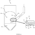
- FIG. 1(a) illustrates a catalyst regenerator 100 implementing a spent catalyst distributor.
- the catalyst regenerator 100 hereinafter, is interchangeably referred to as "regenerator 100".
- the regenerator 100 implements horizontal entry of catalyst and is used for regenerating spent catalyst.
- the catalyst regenerator 100 comprises a regenerator vessel 102 and a spent catalyst distributor 104.
- the regenerator vessel 102 includes an inner wall 106a and an outer wall 106b.
- the regenerator vessel 102 houses a dense phase catalyst bed 108a and a dilute phase catalyst bed 108b.
- the spent catalyst distributor 104 may be installed on either of the lateral sides of the regenerator vessel 102 and may be located above an interface of the dense phase catalyst bed 108a and below an interface of the dilute phase catalyst bed 108b.
- the spent catalyst distributor 104 includes a conduit 110 having a proximal end 112a and a distal end 112b, an opening 114 located at the distal end 112b, and a plurality of orifices 116.
- the proximal end 112a as described herein, may be understood as an end of the spent catalyst distributor 104 connected to a spent catalyst standpipe (shown by dotted lines).
- the proximal end 112a is adapted to receive spent catalyst from a stripper (not shown) of a fluid catalytic cracking (FCC) unit through the spent catalyst standpipe.
- the conduit 110 is cylindrical. As may be understood, the conduit 110 may be of other geometrical shapes suitable for implementation purposes.
- the plurality of orifices 116 is located along a length of the conduit 110 between the distal end 112b and the inner wall 106a of the regenerator vessel 102.
- the length of the conduit 110 between the distal end 112b and the inner wall 106a of the regenerator vessel 102 includes a first circumferential portion 118a and a second circumferential portion 118b (not shown in the figure).
- the second circumferential portion 118b is diametrically opposite to the first circumferential portion 118a.
- a first set of orifices 116a is located on the first circumferential portion 118a and a second set of orifices 116b (not shown in the figure) is located on the second circumferential portion 118b.
- both, the first set of orifices 116a and the second set of orifices 116b include at least four orifices.
- the orifices 116 are placed equidistantly from each other and a distance between two orifices, located adjacent to one another along the length of the conduit 110, is based on a distance between the distal end and proximal end, and catalyst flow rate.
- a diameter of each of the plurality of orifices 116 is in the range of 40 to 60% of a diameter of the conduit 110. In another example, the diameter is in the range of about 50% of the diameter of the conduit 110.
- the proximal end 112a of the conduit 110 receives the spent catalyst from the stripper.
- the conduit 110 may project the spent catalyst horizontally at a plurality of locations inside the regenerator vessel 102.
- the conduit 110 projects the spent catalyst in a manner such that initially, a portion of the spent catalyst ejects out from the plurality of orifices 116 and thereafter, rest of the spent catalyst ejects from the opening 114 located at the distal end 112b.
- the spent catalyst spreads across the regenerator vessel 102.
- Figure 1(b) illustrates a catalyst regenerator 125, in accordance with an example.
- the catalyst regenerator 125 employs horizontal and downward entry of catalyst.
- the spent catalyst distributor 104 is arranged in a manner so as to facilitate horizontal and downward entry of the catalyst.
- the proximal end 112a of the conduit 110 receives the spent catalyst from the stripper.
- the conduit 110 projects the spent catalyst horizontally and downwardly at a plurality of locations inside the regenerator vessel 102.
- the conduit 110 projects the spent catalyst in a manner such that initially, a portion of the spent catalyst ejects out from the plurality of orifices 116. Thereafter, rest of the spent catalyst ejects from the opening 114 located at the distal end 112b.
- angles of projection of the spent catalyst may vary from the angles of projection of the spent catalyst as described in Figure 1a . However, the spent catalyst is well distributed across the regenerator vessel 102.
- FIG. 2 illustrates a catalyst regenerator 200 implementing a spent catalyst distributor, in accordance with another example.
- the catalyst regenerator 200 may interchangeably be referred to as regenerator 200.
- the catalyst regenerator 200 comprises a regenerator vessel 202 and a spent catalyst distributor 204.
- the spent catalyst distributor 204 includes a conduit 206 having a proximal end 208a and a distal end 208b.
- the conduit 206 further includes an opening 210 located at the distal end 208b and a plurality of orifices 212.
- the plurality of orifices 212 is located along a length of the conduit 206 between the distal end 208b and an inner wall 214 of the regenerator vessel 202.
- a diameter of the opening 210 is less than a diameter of the conduit 206.
- the opening 210 may be in the form of a truncated cone-shaped opening.
- the conduit 206 projects the spent catalyst horizontally at a plurality of locations inside the regenerator vessel 202 in a manner such that initially, a portion of spent catalyst ejects out from the plurality of orifices 212. Thereafter, the rest of the spent catalyst ejects out from the opening 210.
- the conduit 206 projects the spent catalyst horizontally and downwardly at a plurality of locations inside the regenerator vessel 202 in a manner such that initially, a portion of spent catalyst ejects out from the plurality of orifices 212. Thereafter, rest of the spent catalyst ejects out from the opening 210.
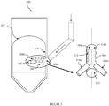
- FIG. 3 illustrates a catalyst regenerator 300 implementing a spent catalyst distributor, in accordance with another example.
- the catalyst regenerator 300 may interchangeably be referred to as regenerator 300.
- the catalyst regenerator 300 comprises a regenerator vessel 302 and a spent catalyst distributor 304.
- the spent catalyst distributor 304 includes a conduit 306 having a proximal end 308a and a distal end 308b.
- the conduit 306 further includes an opening 310, located at the distal end 308b, and a plurality of orifices 312.
- the orifices 312 are located along a length of the conduit 306 between the distal end 308b and an inner wall 314 of the regenerator vessel 302.
- the conduit 306 is provided with one or more extending arms 316.
- the extending arms 316 are provided on at least one of the plurality of orifices 312 and protrude outwardly from the conduit 306. Further, the extending arms 316 are directed inside the regenerator vessel 302. In an example, the extending arms 316 may be placed in a manner such that a first extending arm 316a is located on a first circumferential portion 318a and a second extending arm 316b is located on a second circumferential portion 318b.
- the conduit 306 projects the spent catalyst horizontally at a plurality of locations inside the regenerator vessel 302 in a manner such that initially, a portion of the spent catalyst ejects out from the extending arms 316 and the other plurality of orifices 312. thereafter, rest of the spent catalyst ejects out from the opening 310 located at the distal end 308b.
- the conduit 306 projects the spent catalyst horizontally and downwardly at a plurality of locations inside the regenerator vessel 302 in a manner such that initially, a portion of the spent catalyst ejects out from the extending arms 316 and the other plurality of orifices 312. thereafter, rest of the spent catalyst ejects out from the opening 310 located at the distal end 308b.
- FIG. 4 illustrates a catalyst regenerator 400 implementing a spent catalyst distributor, in accordance with the present invention.
- the catalyst regenerator 400 may interchangeably be referred to as regenerator 400.
- the catalyst regenerator 400 comprises a regenerator vessel 402 and a spent catalyst distributor 404.
- the spent catalyst distributor 404 includes a conduit 406 having a proximal end 408a and a distal end 408b.
- the conduit 406 further includes an opening 410 located at the distal end 408b and a plurality of orifices 412.
- the orifices 412 are located along a length of the conduit 406 between the distal end 408b and an inner wall 414 of the regenerator vessel 402.
- the conduit 406 is provided with at least one baffle 416.
- the at least one baffle 416 directs towards at least one of the plurality of orifices 412 such that the at least one baffle 416 can be located inside the conduit 406.
- the at least one baffle 416 directs the flow of the spent catalyst to the conduit 406. Subsequently, the conduit 406 projects the spent catalyst horizontally at a plurality of locations inside the regenerator vessel 402.
- the at least one baffle 416 used in the present invention directs the flow of the spent catalyst to the conduit 406. Subsequently, the conduit 406 projects the spent catalyst horizontally and downwardly at a plurality of locations inside the regenerator vessel 402.
- Figures 5(a)-5(i) illustrates an exemplary case study, in accordance with an example.
- an experimental apparatus 500 for the case study consists of a catalyst hopper 502, a spent catalyst standpipe 504, a valve 506 and a spent catalyst distributor 508.
- the catalyst hopper 502 is funnel-shaped and is connected to the spent catalyst standpipe 504 that leads to the spent catalyst distributor 508.
- the flow of spent catalyst traveling from the catalyst hopper 502 is regulated by the valve 506.
- the case study is performed without aeration facility.
- the case study is performed with aeration facility provided in both the catalyst hopper 502 and the spent catalyst distributor 508, preferably at the bottom of the spent catalyst distributor 508.
- a ring type air distributor 510 is installed at the bottom of the catalyst hopper 502 and at the beginning of the spent catalyst standpipe 504 that ensures a minimum bubbling velocity in the catalyst hopper.
- total fluidization air to ring air distributor varied from 20 to 50 l/min confirming a minimum bubbling velocity.
- the aeration flow in the catalyst hopper 502 and the spent catalyst distributor 508 is measured and controlled via rotameters. Further, a minimum fluidization velocity is maintained in the spent catalyst standpipe 504 with aeration facility.
- FIG. 5(b) shows a pictorial view of a first embodiment of a spent catalyst distributor employed in the simulation studies.
- the spent catalyst distributor has a cylindrical conduit comprising a proximal end, a distal end, an opening located at the distal end and four equidistantly placed orifices along the length of the cylindrical conduit.
- the four orifices include a first set of orifices and a second set of orifices present on both circumferential portions of the cylindrical conduit and are of equal diameter.
- the length of the spent catalyst distributor is 2.5 times diameter of the spent catalyst distributor.
- the data generated for the first embodiment is shown in Table 2 .
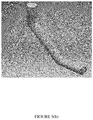
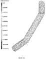
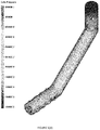
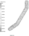
- FIG. 5(c) and 5(d) a pictorial view of a particle volume fraction and a pressure profile for the first embodiment of the spent catalyst distributor with aeration is shown.
- the particle volume fraction is uniform in the range of about 0.3-0.4 and the pressure build-up is negligible.
- FIGs 5(e)-5(f) illustrates an arrangement of aeration at the bottom of the first embodiment of the spent catalyst distributor.
- the aeration media may be air, nitrogen, steam etc or in any combination thereof.
- FIG 5(g) a pictorial view of a second embodiment of a spent catalyst distributor employed in the simulation studies is shown.
- the spent catalyst distributor has a cylindrical conduit comprising a proximal end, a truncated conical end, an opening located at the truncated conical end and four equidistantly placed orifices along the length of the cylindrical conduit.
- the four orifices include a first set of orifices and a second set of orifices present on both circumferential portions of the cylindrical conduit and are of equal diameter.
- the length of the spent catalyst distributor is 2.5 times diameter of the spent catalyst distributor.
- the data generated for the first embodiment is shown in Table 3 .
- FIG. 5(h) and 5(i) a pictorial view of a particle volume fraction and a pressure profile for the second embodiment of the spent catalyst distributor with aeration is shown.
- the particle volume fraction is in the range of about 0.35-0.45 and the pressure build-up is negligible. Based on the above simulation results, it can be concluded that both the first embodiment and the second embodiment are suitable for uniform distribution of spent catalyst with almost no catalyst hold up & negligible pressure buildup inside the catalyst regenerator.
Landscapes
- Chemical & Material Sciences (AREA)
- Organic Chemistry (AREA)
- Chemical Kinetics & Catalysis (AREA)
- Engineering & Computer Science (AREA)
- Oil, Petroleum & Natural Gas (AREA)
- Combustion & Propulsion (AREA)
- General Chemical & Material Sciences (AREA)
- Materials Engineering (AREA)
- Production Of Liquid Hydrocarbon Mixture For Refining Petroleum (AREA)
- Devices And Processes Conducted In The Presence Of Fluids And Solid Particles (AREA)
Claims (9)
- Ein Katalysatorregenerator zur Regeneration eines verbrauchten Katalysators, umfassend:ein Katalysatorregeneratorgefäß (102, 202, 302, 402), das ein Katalysatorbett mit dichter Phase (108a) enthält; undeinen Verteiler für verbrauchten Katalysator (104, 204, 304, 404, 508) umfassend ein Rohr (110, 206, 306, 406), das horizontal oder horizontal und nach unten in das Katalysatorregeneratorgefäß (102, 202, 302, 402) hineinragt, wobei das Rohr (110, 206, 306, 406) umfasst:ein proximales Ende (112a, 208a, 308a, 408a);ein distales Ende (112b, 208b, 308b, 408b);eine Öffnung (114, 210, 310, 410), die sich am distalen Ende (112b, 208b, 308b, 408b) zur Einführung des verbrauchten Katalysators an einer ersten Stelle im Innern des Katalysatorregeneratorgefäßes (102, 202, 302, 402) befindet; undeine Vielzahl an Öffnungen (116, 212, 312, 412) die sich entlang einer Länge des Rohrs (110, 206, 306, 406) zwischen dem distalen Ende (112b, 208b, 308b, 408b) und einer Innenwand (106a, 214, 314, 414) des Katalysatorregeneratorgefäßes (102, 202, 302, 402) zur Einführung des verbrauchten Katalysators an einer Vielzahl an Stellen im Innern des Katalysatorregeneratorgefäßes (102, 202, 302, 402) befinden,wobei jede der Vielzahl an Öffnungen (116, 212, 312, 412), die sich entlang der Länge des Rohrs (110, 206, 306, 406) befinden, einen Durchmesser im Bereich von 40 bis 60% eines Durchmessers des Rohrs (110, 206, 306, 406) besitzt,wobei der Katalysatorregenerator außerdem wenigstens eine Leitfläche umfasst, die innerhalb des Rohrs (110, 206, 306, 406) bereitgestellt ist, um ein Fließen des verbrauchten Katalysators innerhalb des Rohrs (110, 206, 306, 406) in Richtung wenigstens einer der Vielzahl an Öffnungen (116, 212, 312, 412) zu leiten, die sich entlang der Länge des Rohrs (110, 206, 306, 406) befinden.
- Der Katalysatorregenerator nach Anspruch 1, wobei das Rohr (110, 206, 306, 406) sich über einer Grenzfläche des Katalysatorbetts mit dichter Phase (108a) und unter einer Grenzfläche des Katalysatorbetts mit verdünnter Phase (108b) befindet.
- Der Katalysatorregenerator nach Anspruch 1, wobei die Öffnung (114, 210, 310, 410), die sich am distalen Ende (112b, 208b, 308b, 408b) zur Einführung des verbrauchten Katalysators an der ersten Stelle befindet, sich über einer Grenzfläche des Katalysatorbetts mit dichter Phase (108a) und unter einer Grenzfläche des Katalysatorbetts mit verdünnter Phase (108b) befindet.
- Der Katalysatorregenerator nach Anspruch 1, wobei jede der Vielzahl an Öffnungen (116, 212, 312, 412), die sich entlang der Länge des Rohrs (110, 206, 306, 406) befinden, sich über einer Grenzfläche des Katalysatorbetts mit dichter Phase (108a) und unter einer Grenzfläche des Katalysatorbetts mit verdünnter Phase (108b) befindet.
- Der Katalysatorregenerator nach Anspruch 1, wobei die erste Reihe an Öffnungen (116, 212, 312, 412) sich auf einem ersten Umfangsabschnitt des Rohrs (118a, 318a) befindet und die zweite Reihe an Öffnungen (116, 212, 312, 412) sich auf einem zweiten Umfangsabschnitt (118b, 318b) befindet, wobei der zweite Umfangsabschnitt (118b, 318b) diametral gegenüber dem ersten Umfangsabschnitt (118a, 318a) angeordnet ist.
- Der Katalysatorregenerator nach Anspruch 5, wobei die Länge des Rohrs (110, 206, 306, 406) zwischen dem distalen Ende (112b, 208b, 308b, 408b) und der Innenwand (106a, 214, 314, 414) des Katalysatorregeneratorgefäßes (102, 202, 302, 402) wenigstens 4 Öffnungen (116, 212, 312, 412), die sich auf dem ersten Umfangsabschnitt (118a, 318a) befinden, und wenigstens vier Öffnungen (116, 212, 312, 412) umfasst, die sich auf dem zweiten Umfangsabschnitt (118b, 318b) befinden.
- Der Katalysatorregenerator nach Anspruch 1, wobei ein Durchmesser der Öffnung (114, 210, 310, 410), die sich am distalen Ende (112b, 208b, 308b, 408b) befindet, kleiner als ein Durchmesser des Rohrs (110, 206, 306, 406) ist.
- Der Katalysatorregenerator nach Anspruch 1, wobei wenigstens eine der Vielzahl an Öffnungen (116, 212, 312, 412), die sich entlang der Länge des Rohrs (110, 206, 306, 406) befinden, einen nach außen erstreckenden Arm (316) besitzt.
- Der Katalysatorregenerator nach Anspruch 1, wobei jede der Vielzahl an Öffnungen (116, 212, 312, 412), die sich entlang der Länge des Rohrs (110, 206, 306, 406) befinden, einen Durchmesser im Bereich von etwa 50% eines Durchmessers des Rohrs (110, 206, 306, 406) besitzt.
Applications Claiming Priority (1)
| Application Number | Priority Date | Filing Date | Title |
|---|---|---|---|
| IN201721019552 | 2017-06-03 |
Publications (2)
| Publication Number | Publication Date |
|---|---|
| EP3409348A1 EP3409348A1 (de) | 2018-12-05 |
| EP3409348B1 true EP3409348B1 (de) | 2020-07-22 |
Family
ID=61622380
Family Applications (1)
| Application Number | Title | Priority Date | Filing Date |
|---|---|---|---|
| EP18161020.5A Active EP3409348B1 (de) | 2017-06-03 | 2018-03-09 | Vorrichtung zur verteilung eines katalysators in einer katalytischen fliessbett-crackanlage |
Country Status (3)
| Country | Link |
|---|---|
| US (1) | US10646863B2 (de) |
| EP (1) | EP3409348B1 (de) |
| ZA (1) | ZA201801627B (de) |
Families Citing this family (5)
| Publication number | Priority date | Publication date | Assignee | Title |
|---|---|---|---|---|
| BR112018072147A2 (pt) * | 2016-04-29 | 2019-02-12 | Basf Corporation | projeto de unidade de desativação de metal cíclica novo para a desativação de catalisador de fcc |
| EP3939697B1 (de) | 2019-03-18 | 2023-08-02 | Shanghai Supezet Engineering Technology Co., Ltd. | Vorrichtung für katalytische alkandehydrierungsreaktion mit ringförmigem katalysatorverteiler |
| CN111854487B (zh) * | 2020-08-19 | 2024-05-14 | 中国石油大学(北京) | 一种区域协同强化的流化床取热器 |
| US12403440B2 (en) * | 2021-05-18 | 2025-09-02 | Uop Llc | Apparatus for distributing feed with a cluster of orifices on a side of the distributor |
| WO2026047362A1 (en) * | 2024-08-28 | 2026-03-05 | Saudi Arabian Oil Company | Methods for processing hydrocarbons |
Family Cites Families (11)
| Publication number | Priority date | Publication date | Assignee | Title |
|---|---|---|---|---|
| US5635140A (en) | 1995-11-13 | 1997-06-03 | The M. W. Kellogg Company | Self-aerating spent catalyst distributor |
| US5773378A (en) | 1996-10-30 | 1998-06-30 | The M. W. Kellogg Company | Spent catalyst distribution |
| US6503460B1 (en) | 1999-03-17 | 2003-01-07 | Kellogg Brown & Root, Inc. | Staged catalyst regeneration in a baffled fluidized bed |
| US6809054B1 (en) | 2000-11-21 | 2004-10-26 | Uop Llc | FCC spent catalyst distributor |
| US6797239B1 (en) | 2000-11-22 | 2004-09-28 | Shell Oil Company | Spent catalyst distributor |
| CN1208433C (zh) * | 2003-09-02 | 2005-06-29 | 中国石油化工集团公司 | 流化催化裂化装置待生催化剂分配器 |
| US7745365B2 (en) * | 2007-03-09 | 2010-06-29 | Stone & Webster Process Technology, Inc. | Bathtub-type spent catalyst distributor for effective counter-current regeneration in fluid catalytic cracking units |
| US8173567B2 (en) * | 2008-12-16 | 2012-05-08 | Uop Llc | Process for regenerating catalyst |
| US8815165B2 (en) * | 2011-12-19 | 2014-08-26 | Uop Llc | Systems and methods for distributing particulate material into a particulate vessel and FCC units including the systems |
| US10478840B2 (en) * | 2017-06-28 | 2019-11-19 | Indian Oil Corporation Limited | Apparatus and method for converting liquid stream into fine droplets |
| US10578304B2 (en) * | 2017-07-07 | 2020-03-03 | Indian Oil Corporation Limited | Apparatus and method for progressive reduction of flue gas |
-
2018
- 2018-03-09 EP EP18161020.5A patent/EP3409348B1/de active Active
- 2018-03-09 ZA ZA2018/01627A patent/ZA201801627B/en unknown
- 2018-03-12 US US15/918,678 patent/US10646863B2/en active Active
Non-Patent Citations (1)
| Title |
|---|
| None * |
Also Published As
| Publication number | Publication date |
|---|---|
| US10646863B2 (en) | 2020-05-12 |
| EP3409348A1 (de) | 2018-12-05 |
| ZA201801627B (en) | 2019-05-29 |
| US20180345267A1 (en) | 2018-12-06 |
Similar Documents
| Publication | Publication Date | Title |
|---|---|---|
| EP3409348A1 (de) | Vorrichtung zur verteilung eines katalysators in einer katalytischen fliessbett-crackanlage | |
| EP1352038B1 (de) | Verteiler fuer gebrauchte katalysatoren | |
| US4615870A (en) | Back-mixed hydrotreating reactor | |
| CN103906563B (zh) | 装有对水平度缺失很不敏感的分配元件的气液混合物的分配器盘 | |
| CN1371413A (zh) | 用于催化裂化过程的进料喷射系统 | |
| US10076736B2 (en) | Multiple-bed downflow reactor comprising a mixing device, use of said reactor, as well as mixing method | |
| AU2002229564A1 (en) | Spent Catalyst Distributor | |
| WO2014210276A1 (en) | Fluid mixing and distribution device and method for multibed reactors | |
| CN101400511B (zh) | 汽提装置和方法 | |
| US6146519A (en) | Gas solid contact riser with redistribution | |
| EP1967259B1 (de) | Verfahren zur Verteilung von verbrauchtem Katalysator in einem Katalysator-Regenerator einer katalytischen Fluid-Cracking-Einheit | |
| EP3013467B1 (de) | Flüssigkeitsverteilungsvorrichtung und -verfahren für mehrbettreaktoren | |
| US8206657B2 (en) | Enclosure containing a granular bed and a distribution of a gas phase and of a liquid phase circulating in an ascending flow in this enclosure | |
| KR20110101214A (ko) | 촉매 재생 장치 | |
| US20060165605A1 (en) | Process to regenerate fcc spent catalyst | |
| EP2459949B1 (de) | Trennungs- und abscheidungsvorrichtung für externe fcc-steigleitungen und prozess zur abscheidung eine gasmischung und partikelstrom | |
| US6156276A (en) | Distribution apparatus for short time contact of hydrocarbon compounds with particles | |
| US7655589B2 (en) | Process and apparatus for the regeneration of spent FCC catalyst | |
| EP1456325B1 (de) | Verfahren zur regenerierung von gebrauchtem fcc katalysator | |
| EP1156873B1 (de) | Standrohr-einlass fuer zirkulation von partikelförmigen feststoffen in petrochemischen oder anderen prozessen | |
| US3142543A (en) | Apparatus for catalytically cracking hydrocarbons | |
| JP7117105B2 (ja) | 流動固体分配装置 | |
| US2510444A (en) | Apparatus for pyrolytic conversion of hydrocarbons | |
| US20120116136A1 (en) | Device for distributing a polyphase mixture comprising a jet breaker tray with a separating element | |
| CN1453334A (zh) | 一种下行式催化裂化反应器及其应用 |
Legal Events
| Date | Code | Title | Description |
|---|---|---|---|
| PUAI | Public reference made under article 153(3) epc to a published international application that has entered the european phase |
Free format text: ORIGINAL CODE: 0009012 |
|
| STAA | Information on the status of an ep patent application or granted ep patent |
Free format text: STATUS: THE APPLICATION HAS BEEN PUBLISHED |
|
| AK | Designated contracting states |
Kind code of ref document: A1 Designated state(s): AL AT BE BG CH CY CZ DE DK EE ES FI FR GB GR HR HU IE IS IT LI LT LU LV MC MK MT NL NO PL PT RO RS SE SI SK SM TR |
|
| AX | Request for extension of the european patent |
Extension state: BA ME |
|
| STAA | Information on the status of an ep patent application or granted ep patent |
Free format text: STATUS: REQUEST FOR EXAMINATION WAS MADE |
|
| 17P | Request for examination filed |
Effective date: 20190605 |
|
| RBV | Designated contracting states (corrected) |
Designated state(s): AL AT BE BG CH CY CZ DE DK EE ES FI FR GB GR HR HU IE IS IT LI LT LU LV MC MK MT NL NO PL PT RO RS SE SI SK SM TR |
|
| STAA | Information on the status of an ep patent application or granted ep patent |
Free format text: STATUS: EXAMINATION IS IN PROGRESS |
|
| 17Q | First examination report despatched |
Effective date: 20190823 |
|
| GRAP | Despatch of communication of intention to grant a patent |
Free format text: ORIGINAL CODE: EPIDOSNIGR1 |
|
| STAA | Information on the status of an ep patent application or granted ep patent |
Free format text: STATUS: GRANT OF PATENT IS INTENDED |
|
| INTG | Intention to grant announced |
Effective date: 20200424 |
|
| GRAS | Grant fee paid |
Free format text: ORIGINAL CODE: EPIDOSNIGR3 |
|
| GRAA | (expected) grant |
Free format text: ORIGINAL CODE: 0009210 |
|
| STAA | Information on the status of an ep patent application or granted ep patent |
Free format text: STATUS: THE PATENT HAS BEEN GRANTED |
|
| AK | Designated contracting states |
Kind code of ref document: B1 Designated state(s): AL AT BE BG CH CY CZ DE DK EE ES FI FR GB GR HR HU IE IS IT LI LT LU LV MC MK MT NL NO PL PT RO RS SE SI SK SM TR |
|
| REG | Reference to a national code |
Ref country code: GB Ref legal event code: FG4D |
|
| REG | Reference to a national code |
Ref country code: CH Ref legal event code: EP |
|
| REG | Reference to a national code |
Ref country code: DE Ref legal event code: R096 Ref document number: 602018006149 Country of ref document: DE |
|
| REG | Reference to a national code |
Ref country code: AT Ref legal event code: REF Ref document number: 1292896 Country of ref document: AT Kind code of ref document: T Effective date: 20200815 |
|
| REG | Reference to a national code |
Ref country code: IE Ref legal event code: FG4D |
|
| REG | Reference to a national code |
Ref country code: LT Ref legal event code: MG4D |
|
| PG25 | Lapsed in a contracting state [announced via postgrant information from national office to epo] |
Ref country code: SE Free format text: LAPSE BECAUSE OF FAILURE TO SUBMIT A TRANSLATION OF THE DESCRIPTION OR TO PAY THE FEE WITHIN THE PRESCRIBED TIME-LIMIT Effective date: 20200722 Ref country code: ES Free format text: LAPSE BECAUSE OF FAILURE TO SUBMIT A TRANSLATION OF THE DESCRIPTION OR TO PAY THE FEE WITHIN THE PRESCRIBED TIME-LIMIT Effective date: 20200722 Ref country code: HR Free format text: LAPSE BECAUSE OF FAILURE TO SUBMIT A TRANSLATION OF THE DESCRIPTION OR TO PAY THE FEE WITHIN THE PRESCRIBED TIME-LIMIT Effective date: 20200722 Ref country code: LT Free format text: LAPSE BECAUSE OF FAILURE TO SUBMIT A TRANSLATION OF THE DESCRIPTION OR TO PAY THE FEE WITHIN THE PRESCRIBED TIME-LIMIT Effective date: 20200722 Ref country code: FI Free format text: LAPSE BECAUSE OF FAILURE TO SUBMIT A TRANSLATION OF THE DESCRIPTION OR TO PAY THE FEE WITHIN THE PRESCRIBED TIME-LIMIT Effective date: 20200722 Ref country code: PT Free format text: LAPSE BECAUSE OF FAILURE TO SUBMIT A TRANSLATION OF THE DESCRIPTION OR TO PAY THE FEE WITHIN THE PRESCRIBED TIME-LIMIT Effective date: 20201123 Ref country code: BG Free format text: LAPSE BECAUSE OF FAILURE TO SUBMIT A TRANSLATION OF THE DESCRIPTION OR TO PAY THE FEE WITHIN THE PRESCRIBED TIME-LIMIT Effective date: 20201022 Ref country code: GR Free format text: LAPSE BECAUSE OF FAILURE TO SUBMIT A TRANSLATION OF THE DESCRIPTION OR TO PAY THE FEE WITHIN THE PRESCRIBED TIME-LIMIT Effective date: 20201023 Ref country code: NO Free format text: LAPSE BECAUSE OF FAILURE TO SUBMIT A TRANSLATION OF THE DESCRIPTION OR TO PAY THE FEE WITHIN THE PRESCRIBED TIME-LIMIT Effective date: 20201022 |
|
| PG25 | Lapsed in a contracting state [announced via postgrant information from national office to epo] |
Ref country code: RS Free format text: LAPSE BECAUSE OF FAILURE TO SUBMIT A TRANSLATION OF THE DESCRIPTION OR TO PAY THE FEE WITHIN THE PRESCRIBED TIME-LIMIT Effective date: 20200722 Ref country code: PL Free format text: LAPSE BECAUSE OF FAILURE TO SUBMIT A TRANSLATION OF THE DESCRIPTION OR TO PAY THE FEE WITHIN THE PRESCRIBED TIME-LIMIT Effective date: 20200722 Ref country code: LV Free format text: LAPSE BECAUSE OF FAILURE TO SUBMIT A TRANSLATION OF THE DESCRIPTION OR TO PAY THE FEE WITHIN THE PRESCRIBED TIME-LIMIT Effective date: 20200722 Ref country code: IS Free format text: LAPSE BECAUSE OF FAILURE TO SUBMIT A TRANSLATION OF THE DESCRIPTION OR TO PAY THE FEE WITHIN THE PRESCRIBED TIME-LIMIT Effective date: 20201122 |
|
| PG25 | Lapsed in a contracting state [announced via postgrant information from national office to epo] |
Ref country code: NL Free format text: LAPSE BECAUSE OF FAILURE TO SUBMIT A TRANSLATION OF THE DESCRIPTION OR TO PAY THE FEE WITHIN THE PRESCRIBED TIME-LIMIT Effective date: 20200722 |
|
| REG | Reference to a national code |
Ref country code: DE Ref legal event code: R097 Ref document number: 602018006149 Country of ref document: DE |
|
| PG25 | Lapsed in a contracting state [announced via postgrant information from national office to epo] |
Ref country code: EE Free format text: LAPSE BECAUSE OF FAILURE TO SUBMIT A TRANSLATION OF THE DESCRIPTION OR TO PAY THE FEE WITHIN THE PRESCRIBED TIME-LIMIT Effective date: 20200722 Ref country code: DK Free format text: LAPSE BECAUSE OF FAILURE TO SUBMIT A TRANSLATION OF THE DESCRIPTION OR TO PAY THE FEE WITHIN THE PRESCRIBED TIME-LIMIT Effective date: 20200722 Ref country code: CZ Free format text: LAPSE BECAUSE OF FAILURE TO SUBMIT A TRANSLATION OF THE DESCRIPTION OR TO PAY THE FEE WITHIN THE PRESCRIBED TIME-LIMIT Effective date: 20200722 Ref country code: SM Free format text: LAPSE BECAUSE OF FAILURE TO SUBMIT A TRANSLATION OF THE DESCRIPTION OR TO PAY THE FEE WITHIN THE PRESCRIBED TIME-LIMIT Effective date: 20200722 |
|
| PLBE | No opposition filed within time limit |
Free format text: ORIGINAL CODE: 0009261 |
|
| STAA | Information on the status of an ep patent application or granted ep patent |
Free format text: STATUS: NO OPPOSITION FILED WITHIN TIME LIMIT |
|
| PG25 | Lapsed in a contracting state [announced via postgrant information from national office to epo] |
Ref country code: AL Free format text: LAPSE BECAUSE OF FAILURE TO SUBMIT A TRANSLATION OF THE DESCRIPTION OR TO PAY THE FEE WITHIN THE PRESCRIBED TIME-LIMIT Effective date: 20200722 |
|
| 26N | No opposition filed |
Effective date: 20210423 |
|
| PG25 | Lapsed in a contracting state [announced via postgrant information from national office to epo] |
Ref country code: SK Free format text: LAPSE BECAUSE OF FAILURE TO SUBMIT A TRANSLATION OF THE DESCRIPTION OR TO PAY THE FEE WITHIN THE PRESCRIBED TIME-LIMIT Effective date: 20200722 |
|
| PG25 | Lapsed in a contracting state [announced via postgrant information from national office to epo] |
Ref country code: SI Free format text: LAPSE BECAUSE OF FAILURE TO SUBMIT A TRANSLATION OF THE DESCRIPTION OR TO PAY THE FEE WITHIN THE PRESCRIBED TIME-LIMIT Effective date: 20200722 |
|
| REG | Reference to a national code |
Ref country code: NL Ref legal event code: MP Effective date: 20200722 |
|
| PG25 | Lapsed in a contracting state [announced via postgrant information from national office to epo] |
Ref country code: MC Free format text: LAPSE BECAUSE OF FAILURE TO SUBMIT A TRANSLATION OF THE DESCRIPTION OR TO PAY THE FEE WITHIN THE PRESCRIBED TIME-LIMIT Effective date: 20200722 |
|
| REG | Reference to a national code |
Ref country code: CH Ref legal event code: PL |
|
| REG | Reference to a national code |
Ref country code: BE Ref legal event code: MM Effective date: 20210331 |
|
| PG25 | Lapsed in a contracting state [announced via postgrant information from national office to epo] |
Ref country code: CH Free format text: LAPSE BECAUSE OF NON-PAYMENT OF DUE FEES Effective date: 20210331 Ref country code: LU Free format text: LAPSE BECAUSE OF NON-PAYMENT OF DUE FEES Effective date: 20210309 Ref country code: LI Free format text: LAPSE BECAUSE OF NON-PAYMENT OF DUE FEES Effective date: 20210331 Ref country code: FR Free format text: LAPSE BECAUSE OF NON-PAYMENT OF DUE FEES Effective date: 20210331 Ref country code: IE Free format text: LAPSE BECAUSE OF NON-PAYMENT OF DUE FEES Effective date: 20210309 |
|
| PG25 | Lapsed in a contracting state [announced via postgrant information from national office to epo] |
Ref country code: BE Free format text: LAPSE BECAUSE OF NON-PAYMENT OF DUE FEES Effective date: 20210331 |
|
| REG | Reference to a national code |
Ref country code: AT Ref legal event code: UEP Ref document number: 1292896 Country of ref document: AT Kind code of ref document: T Effective date: 20200722 |
|
| GBPC | Gb: european patent ceased through non-payment of renewal fee |
Effective date: 20220309 |
|
| PG25 | Lapsed in a contracting state [announced via postgrant information from national office to epo] |
Ref country code: GB Free format text: LAPSE BECAUSE OF NON-PAYMENT OF DUE FEES Effective date: 20220309 |
|
| PG25 | Lapsed in a contracting state [announced via postgrant information from national office to epo] |
Ref country code: CY Free format text: LAPSE BECAUSE OF FAILURE TO SUBMIT A TRANSLATION OF THE DESCRIPTION OR TO PAY THE FEE WITHIN THE PRESCRIBED TIME-LIMIT Effective date: 20200722 |
|
| PG25 | Lapsed in a contracting state [announced via postgrant information from national office to epo] |
Ref country code: HU Free format text: LAPSE BECAUSE OF FAILURE TO SUBMIT A TRANSLATION OF THE DESCRIPTION OR TO PAY THE FEE WITHIN THE PRESCRIBED TIME-LIMIT; INVALID AB INITIO Effective date: 20180309 |
|
| PG25 | Lapsed in a contracting state [announced via postgrant information from national office to epo] |
Ref country code: MK Free format text: LAPSE BECAUSE OF FAILURE TO SUBMIT A TRANSLATION OF THE DESCRIPTION OR TO PAY THE FEE WITHIN THE PRESCRIBED TIME-LIMIT Effective date: 20200722 |
|
| PG25 | Lapsed in a contracting state [announced via postgrant information from national office to epo] |
Ref country code: MT Free format text: LAPSE BECAUSE OF FAILURE TO SUBMIT A TRANSLATION OF THE DESCRIPTION OR TO PAY THE FEE WITHIN THE PRESCRIBED TIME-LIMIT Effective date: 20200722 |
|
| PGFP | Annual fee paid to national office [announced via postgrant information from national office to epo] |
Ref country code: DE Payment date: 20250331 Year of fee payment: 8 |
|
| PGFP | Annual fee paid to national office [announced via postgrant information from national office to epo] |
Ref country code: IT Payment date: 20250327 Year of fee payment: 8 |
|
| PGFP | Annual fee paid to national office [announced via postgrant information from national office to epo] |
Ref country code: AT Payment date: 20260309 Year of fee payment: 9 |
|
| PGFP | Annual fee paid to national office [announced via postgrant information from national office to epo] |
Ref country code: RO Payment date: 20260309 Year of fee payment: 9 |
|
| PGFP | Annual fee paid to national office [announced via postgrant information from national office to epo] |
Ref country code: TR Payment date: 20260309 Year of fee payment: 9 |