EP1966551B1 - Coolant compressor - Google Patents
Coolant compressor Download PDFInfo
- Publication number
- EP1966551B1 EP1966551B1 EP06830753A EP06830753A EP1966551B1 EP 1966551 B1 EP1966551 B1 EP 1966551B1 EP 06830753 A EP06830753 A EP 06830753A EP 06830753 A EP06830753 A EP 06830753A EP 1966551 B1 EP1966551 B1 EP 1966551B1
- Authority
- EP
- European Patent Office
- Prior art keywords
- compressor housing
- collection container
- receptacle
- collecting container
- cover part
- Prior art date
- Legal status (The legal status is an assumption and is not a legal conclusion. Google has not performed a legal analysis and makes no representation as to the accuracy of the status listed.)
- Active
Links
Images


Classifications
-
- F—MECHANICAL ENGINEERING; LIGHTING; HEATING; WEAPONS; BLASTING
- F25—REFRIGERATION OR COOLING; COMBINED HEATING AND REFRIGERATION SYSTEMS; HEAT PUMP SYSTEMS; MANUFACTURE OR STORAGE OF ICE; LIQUEFACTION SOLIDIFICATION OF GASES
- F25D—REFRIGERATORS; COLD ROOMS; ICE-BOXES; COOLING OR FREEZING APPARATUS NOT OTHERWISE PROVIDED FOR
- F25D21/00—Defrosting; Preventing frosting; Removing condensed or defrost water
- F25D21/14—Collecting or removing condensed and defrost water; Drip trays
-
- F—MECHANICAL ENGINEERING; LIGHTING; HEATING; WEAPONS; BLASTING
- F04—POSITIVE - DISPLACEMENT MACHINES FOR LIQUIDS; PUMPS FOR LIQUIDS OR ELASTIC FLUIDS
- F04B—POSITIVE-DISPLACEMENT MACHINES FOR LIQUIDS; PUMPS
- F04B39/00—Component parts, details, or accessories, of pumps or pumping systems specially adapted for elastic fluids, not otherwise provided for in, or of interest apart from, groups F04B25/00 - F04B37/00
- F04B39/12—Casings; Cylinders; Cylinder heads; Fluid connections
- F04B39/121—Casings
-
- F—MECHANICAL ENGINEERING; LIGHTING; HEATING; WEAPONS; BLASTING
- F25—REFRIGERATION OR COOLING; COMBINED HEATING AND REFRIGERATION SYSTEMS; HEAT PUMP SYSTEMS; MANUFACTURE OR STORAGE OF ICE; LIQUEFACTION SOLIDIFICATION OF GASES
- F25D—REFRIGERATORS; COLD ROOMS; ICE-BOXES; COOLING OR FREEZING APPARATUS NOT OTHERWISE PROVIDED FOR
- F25D2321/00—Details or arrangements for defrosting; Preventing frosting; Removing condensed or defrost water, not provided for in other groups of this subclass
- F25D2321/14—Collecting condense or defrost water; Removing condense or defrost water
- F25D2321/141—Removal by evaporation
- F25D2321/1411—Removal by evaporation using compressor heat
-
- F—MECHANICAL ENGINEERING; LIGHTING; HEATING; WEAPONS; BLASTING
- F25—REFRIGERATION OR COOLING; COMBINED HEATING AND REFRIGERATION SYSTEMS; HEAT PUMP SYSTEMS; MANUFACTURE OR STORAGE OF ICE; LIQUEFACTION SOLIDIFICATION OF GASES
- F25D—REFRIGERATORS; COLD ROOMS; ICE-BOXES; COOLING OR FREEZING APPARATUS NOT OTHERWISE PROVIDED FOR
- F25D2321/00—Details or arrangements for defrosting; Preventing frosting; Removing condensed or defrost water, not provided for in other groups of this subclass
- F25D2321/14—Collecting condense or defrost water; Removing condense or defrost water
- F25D2321/144—Collecting condense or defrost water; Removing condense or defrost water characterised by the construction of drip water collection pans
- F25D2321/1442—Collecting condense or defrost water; Removing condense or defrost water characterised by the construction of drip water collection pans outside a refrigerator
-
- F—MECHANICAL ENGINEERING; LIGHTING; HEATING; WEAPONS; BLASTING
- F25—REFRIGERATION OR COOLING; COMBINED HEATING AND REFRIGERATION SYSTEMS; HEAT PUMP SYSTEMS; MANUFACTURE OR STORAGE OF ICE; LIQUEFACTION SOLIDIFICATION OF GASES
- F25D—REFRIGERATORS; COLD ROOMS; ICE-BOXES; COOLING OR FREEZING APPARATUS NOT OTHERWISE PROVIDED FOR
- F25D2321/00—Details or arrangements for defrosting; Preventing frosting; Removing condensed or defrost water, not provided for in other groups of this subclass
- F25D2321/14—Collecting condense or defrost water; Removing condense or defrost water
- F25D2321/145—Collecting condense or defrost water; Removing condense or defrost water characterised by multiple collecting pans
Definitions
- the invention relates to a compressor housing having a cover part and a base part, which encloses a small refrigerant compressor hermetically sealing, wherein the compressor housing a plastic container made for the evaporation of condensed liquid is provided, which is held in a housing formed on the compressor housing, according to the preamble of claim 1 and a method for producing and mounting a collecting container made of plastic on a compressor housing according to the preamble of claim 11.
- Such small refrigerant compressors are mainly used in household use, where they are usually located at the back of a refrigerator. Their task is to compress a refrigerant circulating in the cooling system and memorizube patn, whereby heat dissipated from the interior of the refrigerator, discharged to the environment and a cold room or shelf is thus cooled.
- the refrigerant compressor comprising a hermetically sealed compressor housing has an electric motor which drives a piston oscillating in a cylinder for compressing the refrigerant via a crankshaft.
- the compressor housing consists of a cover part and a base part, wherein supply and discharge lines are provided, which lead out into the compressor housing and out of this, to transport the refrigerant to the cylinder and from this again in the cooling circuit.
- the collecting container is arranged in a vicinity of the compressor housing of the refrigerant compressor, since this represents a heat source and favors the evaporation of the collected liquid.
- Sumps are known from the prior art, which are designed as a separate component and are mounted in the region of the refrigerant compressor, for example via a metal bracket.
- the WO 1999/060317 A1 discloses, for example, arranged on the cover part of a compressor housing, made of plastic Verdunsterschale having a matched to the surface of the compressor housing bottom and is secured with double-sided adhesive tapes on the compressor housing.
- the adhesive tapes can be sunk in small recesses on the surface of the compressor housing.
- the evaporator shell itself forms a receptacle which is slipped over the cover part of the compressor housing.
- an evaporation device for melt water which has a mounted on the compressor housing and adapted to the shape of plastic collecting container in which by providling a smaller wall thickness of the bottom portion relative to that of the other wall sections, a heat-insulating effect of the collecting tank is to be prevented, however, here also an air gap between Compressor housing and sump can not be excluded or minimized satisfactorily.
- thermoplastic materials which attach themselves to the compressor housing at high operating temperatures, it can also in the case of such softening of the material to an undesirable rejection of the collecting container or even an air bubble formation, since the leading to softening thermodynamic process not controlled and actively controlled runs. Since the described nestling of the collecting container to the compressor housing takes place only at high operating temperatures, thus no factory finished compressor / evaporation system can be delivered to the customer, which has the required sauceleitspezmaschinen from the beginning.
- the compressor housing of the small refrigerant compressor to which the condensate condensing liquid collecting tank is arranged, comprises a lid part and a base part enclosing a hermetically sealed volume with each other, wherein the collecting tank is made of thermoplastic resin and the bottom of the collecting tank is the shape of the lid part of the compressor housing is adapted and adjacent to this, to allow a good heat transfer from the small refrigerant compressor to the sump.
- the collecting container is a plastic part which is deep-drawn directly on the compressor housing.
- a plastic part which receives its deformation by a deep-drawing process, which takes place directly on the components of the compressor housing, which form a receptacle for the sump, a snug fit adaptation of the sump to those contact surfaces of Recording and ensures optimum heat transfer from the compressor housing to the collection can be achieved.
- plastic part produced by means of a method according to claim 11, which is shaped to form the collecting container according to the invention it can be a part deep-drawn by means of conventional mechanical media or by means of pressurized fluids or a vacuum.
- the receptacle of at least one holding element which is preferably made of metallic material, and formed a portion of the surface of the lid part.
- the holding element has a holding function for the collecting container, on the other hand, it also has a cooling rib function in that it continuously dissipates heat from the compressor housing to the environment and thus also promotes evaporation of condensate liquid in the collecting container.
- the at least one retaining element is arranged on the cover part, preferably on the outer circumference of the cover part, projecting therefrom and has an upwardly open, shaft-like shape closed along its circumference. In this way, a solid and easy to be produced enclosure is created for the sump.
- the at least one shaft-like holding element expediently has a circular, elliptical or rectangular cross-section. In general, it will correspond in shape to the shape of the compressor housing to correspond with its circumference.
- a portion of the holding element was formed in a preferred embodiment simultaneously as a sealing connection element of the cover part and base part of the compressor housing and is preferably welded to the compressor housing.
- the attachment of the retaining element on the compressor housing can also be realized by a screw, solder, or other connection. If the retaining element attached only to the cover part, but not connected to the base part, is also a one-piece design of Cover part and holding element conceivable in the casting process or deep-drawing process.
- the holding element does not completely the collecting container, but only at selected portions of its circumference, wherein according to the characterizing features of claim 4, a toothed shape of the holding member is proposed.
- the collecting container projects beyond the upper end region of the receptacle.
- the holding element comprises the collecting container only at a partial area of the height of the collecting container, in that the holding element is made only as high as is useful for the cooling rib effect and necessary for the holding function.
- the collecting container on its side facing the cover part on at least one receiving slot, in which the holding element is insertable. It can be provided that the receiving slot has a depth which is less than the height of the collecting container, preferably less than 50% of the height of the collecting container. In this way, a reliable attachment of the collecting container is ensured on the compressor housing.
- the region of the transition from the holding element to the lid part is additionally provided with a coating, preferably of plastic or lacquer.
- a coating preferably of plastic or lacquer.
- the sump next to a main volume also has a serving as an overflow vessel additional volume.
- This is separated from the main volume by a web-like wall or elevation, wherein according to the characterizing features of claim 7, an overflow edge formed by the web-like wall is arranged below the level of a horizontally projected edge of the upper edge region of the collecting container, so that the main volume and additional volume communicate with each other Forming a vessel.
- a temporary excess capacity of condensate liquid is collected in this way in a specially designated reservoir and subsequently brought to evaporate as well.
- the web-like wall is formed according to a further preferred embodiment of the invention by that region of the collecting container, with which this is placed on the holding element.
- the container parts delimiting the main volume and the additional volume of the collecting container can be made in one piece, in which case the container part delimiting the additional volume is preferably designed with a larger wall thickness than the main volume delimiting Container part in order to ensure sufficient stability, since the container volume limiting the additional volume is usually arranged freely suspended and without further support on the outside of the holding element (see Fig. 9 ).
- the container parts delimiting the main volume and the additional volume of the collecting container are manufactured as separate parts, which in the form of their contact surfaces correspond to one another in the mounted state.
- the container part delimiting the additional volume is in this case preferably produced as a deep-drawn part made of plastic.
- the container part delimiting the additional volume of the collecting container may be injection-molded onto the circumferential end region of the collecting container according to the characterizing features of claim 8 by means of a thermoplastic method.
- the retaining element In order to allow during the deep drawing process, an escape of air, which is located in a gap between the cover part of the compressor housing and sump, the retaining element according to the characterizing features of claim 9 is provided with holes. The same holes are also used to prevent corrosion on the compressor housing due to condensed air moisture or in the gap creeping in overflow liquid.
- Suitable materials for the collecting container according to the characterizing features of claim 10 deep-drawable polyethylene terephthalate (PET) or polyamide (PA) or Polybuthylenterephthalat (PBT, PBTP) or thermoplastic polyurethane (TPU) are used.
- PET deep-drawable polyethylene terephthalate
- PA polyamide
- PBT Polybuthylenterephthalat
- TPU thermoplastic polyurethane
- Claim 11 proposes a special method for producing and mounting a plastic collecting container on a compressor housing according to one of the preceding claims in order to minimize or completely eliminate the extent of air gap formation between collecting container and compressor housing or holding element.
- the collecting container is positioned as a blank on the recording provided for him the compressor housing and then brought by force of a pressure medium, preferably under the influence of heat in its final assembly form, so that in the receptacle located portion of the collecting container of the shape of the receptacle.
- the blank may be either a prefabricated with large tolerances, already in about the representational fit of the collection corresponding plastic part or even a more or less deformable, not yet preformed material element, for example in the form of a plate or a piece of a material winding roll. In the latter case, the blank receives its first and at the same time final deformation by being pressed against the receptacle intended for it.
- the pressure medium used is a liquid or gaseous medium.
- the collecting container blank is in this case subjected to compressed air, or with any other fluid such as hot gas or hot liquid, so that the shape of the collecting container directly and accurately to the adjacent surfaces of the recording, so to the compressor housing, holding element and any additional component elements appends.
- a mechanical tension / compression deformation by means of a deep-drawing die is characterized by a procedurally simpler forming process, which eliminates the need for measures to restrict and seal the pressure region, as required in the case of the use of liquid or gaseous media.
- the shape of the thermoforming stamp corresponds to the shape of the volume bounded by the recording, so that the mechanical pressure means or the deep-drawing die has a positive shape which fills a predetermined by the recording negative mold.
- the collecting container is stretched as a blank in foil form over the open cross section of the holding element of the receptacle, while the portion of the lid part bounded by the holding element and functioning as a foil acts as a deep-drawing die.
- the cover part which is preferably guided by the inner wall of the holding element, is moved as a pressure medium against the tensioned blank in film form and finally adapts it to its surface shape until a deformation of the blank adapted to the take-up is achieved.
- the movement of the cover part can be carried out both automatically and manually.
- a negative pressure medium or a vacuum pump can likewise be used in the method according to the invention.
- the vacuum pump is attached via a corresponding suction device to at least one opening of the receptacle, preferably on a plurality of holes having portion of the holding element, in order to then after sealing the between recording and Sump existing volume to exert a negative pressure effect on this volume or on the sump.
- the collecting container is drawn into the shape of the recording and this exactly matched.
- the force effect of the pressure or vacuum means is carried out on the collecting container under the action of heat.
- This promotes a simpler plastic deformation of the collecting container blank and allows an optimal nestling ebendieses this to the adjacent components.
- a complete exclusion of air gaps between the collecting container and its receptacle can be ensured by the cover part is heated to a temperature which leads to a plastic softening of the collecting container in its edge regions, so that the material of the collecting container with the surface of the cover part remaining combines.
- a small refrigerant compressor according to the invention is shown, wherein the compressor housing comprises a base part 3 and a cover part 1, which bound together a hermetically sealed space.
- a piston-cylinder unit not shown, is arranged in a known manner, which is connected to a suction pipe and a pressure tube, wherein a refrigerant flows through the suction pipe to the piston-cylinder unit and the pressure tube condenses the refrigerant there from the inside of the compressor housing leads out again.
- the small refrigerant compressor is in turn attached to a small refrigeration machine, where it is responsible for the heat removal from a refrigerated space of the small refrigerator. Also shown are mounting flanges 20, by means of which the small refrigerant compressor is attached to the small refrigerating machine and an adapter flange 21, via which the supply of the small refrigerant compressor takes place with electrical energy.
- the upper region of the cover part 1 forms a receptacle 6, together with an annular retaining element 2 arranged on the compressor housing which an inventive collecting container 4 made of plastic can be used.
- the heat generated in the interior of the compressor housing is thus transmitted in this arrangement both on the cover part 1, in particular section 16 of the cover part 1, as well as on the holding element 2 to the collecting container 4.
- the preferably made of steel retaining element 2 can be arranged either on the cover part or on the base part 3, but is positioned in a preferred construction as a sealing connection element with a portion 17 directly to the contact edges of the cover part and base part, where it is usually welded to the two Compressor housing parts inseparably connect to each other (see also Figure 3 or the representation of the welds 8 in Figure 10 ).
- the attachment of the retaining element on the compressor housing can also be accomplished by a screw, solder, or other connection.
- a one-piece design of the retaining element with the cover or base part in the casting or deep drawing process is possible.
- the shape of the holding element 2 may vary according to the modeling of the compressor housing or the cover part 1, but will usually be designed round or oval, wherein the collecting container 4 is annularly enclosed along its circumference to ensure a sufficient holding function.
- the holding element 2 is cylindrically formed with an axis in the vertical direction, relative to the support surface or the mounting flanges 20 of the compressor housing, arranged so as to be easily centered and mounted on the compressor housing.
- the holding element 2 also has a heat-transferring function for the collecting container 4, in particular in the case of a metallic design, because it continuously dissipates heat from the compressor housing to the environment and thus also to the adjacent collecting container 4 as a result of its cooling rib function and thus evaporates in the collecting container 4 Condensate liquid forced.
- the collecting container 4 is thus not only “heated” by its bottom, but also by its side walls.
- the holding element 2 In order to increase the cooling rib effect of the holding element 2 still, its wall, as in Figure 12 represented, still be provided with shaft-like cavities 18.
- the cavities 18 expediently extend through the entire longitudinal cross section of the holding element 2, favoring a convective high flow of air and thus promote the removal of heat from the compressor housing to the environment.
- the cavities 18 may be provided in any number in the retaining element 2, wherein the design of their course within the walls of the support member 2 and the connection of the cavities 18 are subject to each other completely free discretion.
- the invention immediately deepened on the compressor housing collecting container 4 is according to Figure 3 is positioned on the receptacle 6 formed by a portion 16 of the lid part 1 and the holding element 2, in which he after applying the manufacturing or
- the shape of the collecting container 4 is in each case exactly adapted to the surface profile of the compressor housing, in particular that of the section 16 of the cover part 1.
- the cover part 1 will usually specify a convex curvature, but may also have any other specific shapes for acoustic or other technical reasons, to which the shape of the collecting container 4 is to be adapted.
- blank 4 plastic part from which the collecting container 4 is formed can be positioned in gradually different pre-machined states on the receptacle 6.
- the blank 4 can be a plastic part which is already prefabricated as standard with a negative tolerance, so that it already essentially corresponds to the shape of the receptacle 6, into which it is used for further assembly, or even to a completely unshaped plastic part, which is only during the assembly on the compressor housing receives its initial and final use form by an appropriate Umformungs vide.
- a completely unshaped plastic part or blank 4 a plate or a film may be mentioned.
- a blank 4 inserted in the form of a film offers not only its advantage of particular conformability but also the advantage of low space requirements during transport of the material, since the film can be transported particularly easily as separable endless material in wound or folded form.
- the blank 4 may also be a combination of prefabricated and unshaped plastic parts, for example, by a film surface is provided with a reinforced, bead-like edge element, said bead-like edge element on the holding element 2 of the receptacle 6 is placed to a reinforced during the forming process Abutment to offer.
- Polybuthylene terephthalate (PBT, PBTP), thermoplastic polyurethane (TPU), polyethylene terephthalate (PET), polypropylene (PP) or polyamide (PA) are preferably used as materials for the collecting container 4, since these are used in the production or assembly process according to the invention by their Prove special plastic properties and their strength characteristics.
- the collecting container 4 is now used as a blank 4 in the receptacle 6 and then brought by means of force of a pressure or vacuum means in its final form of assembly.
- liquid or gaseous media such as compressed air or water
- mechanical pressure means such as thermoforming punches, plungers or matrices in question.
- liquid or gaseous media as a pressure medium of the intended volume range of the receptacle 6 after the delimitation and sealing of the pressure range by suitable measures, preferably applied with hot gases or liquids, so that the shape of the collecting container 4 directly and accurately to the adjacent surfaces of the receptacle 6, so the compressor housing, retaining element 2 and any additional component elements such as screw or snaps attaches.
- thermoforming punch will correspond to the shape of the volume bounded by the receptacle 6.
- the tensioning of the film on the holding element 2 is accomplished by means of conventional measures for clamping, for example by cuffs or suitable selective clamping.
- cover part 1 While the cover part 1 together with the holding element 2 acts as a deep-drawing die, it preferably experiences its guidance on the inner wall of the holding element 2.
- the shaping movement of the cover part 1 can be automated as well be carried out by hand, wherein the holding element 2 is rigidly fixed by a suitable holding device.
- a vacuum pump can also be used in the method according to the invention.
- the vacuum pump is attached via a corresponding suction device to at least one opening of the receptacle 6, preferably on a plurality of bores 13 having portion of the holding member 2, and then after sealing the existing between receiving 6 and 4 collection volume 7 a negative pressure effect on this volume or to exercise on the collecting container 4.
- the collecting container or blank 4 is drawn into the shape of the receptacle 6 and this exactly matched.
- the sealing of the vacuum area is carried out by means of conventional methods such as a radially on the holding element 2 terminals of the edge region of the collecting container 4. Since the holding element 2 is welded in a preferred embodiment of the compressor housing, it usually requires no further measures to the joints of Seal cover part 1 and retaining element 2.
- the reshaping of the collecting container or blank 4 is expediently carried out under external heat action in all the described methods, whereby a simpler plastic deformation of the collecting container or blank 4 and optimum nestling thereof into the receptacle 6 is made possible. In this way, heat transfer-preventing air gaps are minimized as far as possible, whereby even a complete exclusion of air gaps between the sump 4 and its receptacle 6 can be achieved by the cover part 1 and the collecting container 4 is heated to the softening temperature of the collecting container 4, so that in melts its edges to connect with the surface of the lid part 1 lasting.
- An attachment of the collecting container 4 in the receptacle 6 can be done either by a precise insertion or press-fitting in this or by an additional fixing with suitable mechanical fastening parts such as screws, clamps or latches.
- suitable mechanical fastening parts such as screws, clamps or latches.
- the use of temperature-resistant adhesives for fastening purposes is also possible.
- the upper protruding edge region of the sump wall may be wrapped around the support member 2, so as to form a receiving slot 15 and to ensure optimum hooking of the collecting container 4 in the receptacle 6. Furthermore, there is the possibility of rigidly and sealingly fixing the same edge area of the collecting container wall on holding element 2 by heat or adhesive, so that diffusion of liquid overflowing from collecting vessel 4 or condensate vapor into the region between receiving 6 and collecting container 4 is precluded.
- the holding element 2 may be provided with holes for the purpose of removing condensate between receptacle 6 and 4.
- the lid part 1 facing receiving slot 15, in which the holding element 2 is inserted can optionally also be prepared by milling, slitting or other non-cutting or machining method, whereby a plurality of receiving slots 15 may be provided in the collecting container 4 and the chipless or machining preferably takes place in a thickened region of the collecting container wall, so that a sufficient strength of the receiving slot 15 forming region is ensured.
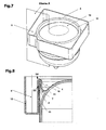
- FIG. 5 A special variant is in Figure 5 shown, where Figure 6 an enlarged view of the detail ZX Figure 5 shows.
- the holding element 2 and the receptacle 6 comprises the collecting container 4 only at a portion of the height of the collecting container 4, by running only as high as it makes sense for its cooling rib effect and for its holding function.
- the receiving slot 15 has a depth which is smaller than 50% of the height of the collecting container 4.
- the wall of the collecting container 4 is turned over in the embodiment shown at a desired final height of the collecting container 4 and again led down to an arbitrary area of the holding element 2, so that now on the holding member 2 protruding part of the collecting container 4 has a double wall.
- the collecting container 4 has according to the in the FIGS. 7 to 9
- This additional volume 9 is separated from the main volume 10 by a web-like wall 14 with an overflow edge 11, wherein the overflow edge 11 below the level of a horizontal projected edge of the upper edge region of the collecting container 4 is arranged, so that the Main volume 10 and the additional volume 9 delimiting container parts together form a communicating vessel.
- the web-like wall 14 can come about either by turning the collecting tank wall (as shown) or by attached to the sump 4, separate profile parts. Conveniently, the web-like wall 14 is formed by that region of the collecting container 4, with which this is placed on the holding element 2.
- delimiting container parts of the additional volume 9 delimiting container part is preferably designed with a larger wall thickness than the main volume 10 delimiting container part to ensure sufficient stability, since the additional volume 9 limiting container part is usually arranged freely hanging on the outside of the holding element 2 and also the notch effect of the holding element 2 is exposed, on which it rests (see Figure 9 ).
- the main volume 10 and the additional volume 9 of the collecting container 4 delimiting container parts of the collecting container 4 can also according to Figure 8 be designed as separate parts which correspond in the form of their contact surfaces in the assembled state with each other.
- the additional volume 9 delimiting container part 12 is here preferably made as a deep-drawn part made of plastic or as a glass fiber reinforced injection molded part made of PBT, but may also be made of a metallic material.
- delimiting container part 12 is molded onto the peripheral end portion 19 of the preferably designed in PET film collecting container 4 by thermoplastic method or the peripheral end portion 19 of the collecting container 4 overmoulded (see fig.11 ).
- the holding element 2 bores 13.
- Figure 10 represents a further measure to protect particularly vulnerable areas of the compressor housing, especially the areas of the welds 8 and the substantially gap-shaped area 5 between the holding element 2 and the cover part 1, especially against corrosion.
- the region 5 of the transition from the holding element 2 or the in Fig. 5 shown section 17 of the holding element 2 to cover part 1 additionally provided with a coating, which may be, for example, plastic, a special finish or a metallic coating.
Description
Die Erfindung bezieht sich auf ein Kompressorgehäuse mit einem Deckelteil und einem Basisteil, welches einen Kleinkältemittelkompressor hermetisch abdichtend umschließt, wobei am Kompressorgehäuse ein aus Kunststoff gefertigter Sammelbehälter zur Verdunstung von kondensierter Flüssigkeit vorgesehen ist, der in einer am Kompressorgehäuse ausgebildeten Aufnahme gehalten ist, gemäß dem Oberbegriff des Anspruchs 1 und ein Verfahren zur Herstellung und Montage eines Sammelbehälters aus Kunststoff an einem Kompressorgehäuse gemäß dem Oberbegriff des Anspruchs 11.The invention relates to a compressor housing having a cover part and a base part, which encloses a small refrigerant compressor hermetically sealing, wherein the compressor housing a plastic container made for the evaporation of condensed liquid is provided, which is held in a housing formed on the compressor housing, according to the preamble of
Derartige Kleinkältemittelkompressoren finden vorwiegend im Haushaltsbereich Einsatz, wo sie zumeist an der Rückseite eines Kühlschranks angeordnet sind. Ihre Aufgabe ist es, ein im Kühlsystem zirkulierendes Kältemittel zu komprimieren und weiterzubefördern, wodurch Wärme aus dem Inneren des Kühlschranks abgeführt, an die Umgebung abgegeben und ein Kühlraum oder Kühlregal somit gekühlt wird.Such small refrigerant compressors are mainly used in household use, where they are usually located at the back of a refrigerator. Their task is to compress a refrigerant circulating in the cooling system and weiterzubefördern, whereby heat dissipated from the interior of the refrigerator, discharged to the environment and a cold room or shelf is thus cooled.
Der ein hermetisch abgedichtetes Kompressorgehäuse umfassende Kältemittelkompressor weist einen Elektromotor auf, welcher über eine Kurbelwelle einen in einem Zylinder oszillierenden Kolben zur Verdichtung des Kältemittels antreibt. Das Kompressorgehäuse besteht dabei aus einem Deckelteil und einem Basisteil, wobei Zu- und Abführleitungen vorgesehen sind, welche in das Kompressorgehäuse und aus diesem herausführen, um das Kältemittel zum Zylinder und von diesem wieder in den Kühlkreislauf zu befördern.The refrigerant compressor comprising a hermetically sealed compressor housing has an electric motor which drives a piston oscillating in a cylinder for compressing the refrigerant via a crankshaft. The compressor housing consists of a cover part and a base part, wherein supply and discharge lines are provided, which lead out into the compressor housing and out of this, to transport the refrigerant to the cylinder and from this again in the cooling circuit.
Während des Betriebes eines Kühlgerätes erweist sich vielfach die Tatsache als problematisch, dass kondensierte Flüssigkeit anfällt, insbesondere aufgrund lokal auftretender, niedriger Temperaturen kondensierte Luftfeuchtigkeit, welche einer Sammlung in eigens dafür vorgesehenen Sammelbehältern bedarf. Diese Sammelbehälter müssen entweder regelmäßig entleert werden, oder sie gewährleisten aufgrund geeigneter Ausführung und Anordnung eine ausreichende Verdunstungsleistung, damit kondensierte Flüssigkeit wieder in den gasförmigen Zustand übergeführt wird und aus dem Bereich der Kleinkältemaschine entweichen kann.During the operation of a refrigerator, the fact often proves to be problematic that condensed liquid is obtained, in particular due to locally occurring, low temperatures condensed humidity, which requires a collection in specially designated collection containers. These sumps must either be emptied regularly, or they ensure adequate evaporation performance due to suitable design and arrangement, so that condensed liquid is transferred back into the gaseous state and can escape from the area of the small refrigerator.
Zweckmäßigerweise wird der Sammelbehälter in einer Nähe zum Kompressorgehäuse des Kältemittelkompressors angeordnet, da dieser eine Wärmequelle darstellt und das Verdunsten der aufgefangenen Flüssigkeit begünstigt. Aus dem Stand der Technik sind Sammelbehälter bekannt, die als separates Bauelement ausgeführt sind und im Bereich des Kältemittelkompressors montiert werden, beispielsweise über einen Metallbügel.Conveniently, the collecting container is arranged in a vicinity of the compressor housing of the refrigerant compressor, since this represents a heat source and favors the evaporation of the collected liquid. Sumps are known from the prior art, which are designed as a separate component and are mounted in the region of the refrigerant compressor, for example via a metal bracket.
Es sind aber auch Sammelbehälter bekannt, beispielsweise aus der
Aus diesem Grunde böte sich die Möglichkeit, aus Kunststoff gefertigte Sammelbehälter einzusetzen, welche gegenüber Stahlsammelbehältern jedoch den Nachteil einer geringeren Verdunsterleistung aufweisen und eine geringere Kompressor-Leistungszahl (COP, Coefficient of Performance) bewirken, da sie aufgrund ihrer geringeren Wärmeleitfähigkeit einen unerwünschten wärmeisolierenden Effekt auf das Kompressorgehäuse ausüben.For this reason, there would be the possibility to use made of plastic storage tanks, which, however, have the disadvantage of lower Verdunsterleistung compared to Stahlsammelbehältern and cause a lower compressor coefficient of performance (COP, Coefficient of Performance), as they due to their lower thermal conductivity an undesirable heat-insulating effect exert the compressor housing.
Neben der geringeren Wärmeleitfähigkeit von Kunststoff verhindert vor allem die bisher praktizierte Montagetechnik der Sammelbehälter am Kompressorgehäuse des Kleinkältemittelkompressors einen optimalen Wärmeübergang, da durch die Befestigung mittels Manschetten, Metallbügeln und Verschraubungen stets ein wärmetechnisch beträchtlicher Luftspalt zwischen Kompressorgehäuseoberfläche und Sammelbehälter entsteht.In addition to the lower thermal conductivity of plastic especially prevents the hitherto practiced assembly of the sump on the compressor housing of the small refrigerant compressor optimum heat transfer, as always by attaching means cuffs, metal brackets and fittings a thermally significant air gap between the compressor housing surface and collecting container.
Die
Allgemein kann also gesagt werden, dass Stahlsammelbehälter gegenüber Kunststoffsammelbehältern zwar eine größere Verdunsterleistung aufweisen und eine höhere Kompressor-Leistungszahl (COP) bewirken, jedoch aufgrund ihrer Korrosionsanfälligkeit einen größeren fertigungs- bzw. wartungstechnischen Aufwand beanspruchen. Hingegen entfallen bei Kunststoffsammelbehältern sämtliche Maßnahmen zum Korrosionsschutz, wobei jedoch der beschriebene Luftspalt zufolge der Anbringung am Kompressorgehäuse die Verdunsterleistung und die Leistungszahl (COP) des Kompressors nachteilig beeinflusst.In general, therefore, it can be said that steel headers have a greater Verdunsterleistung compared to plastic headers and cause a higher compressor COP, but due to their susceptibility to corrosion require a greater production and maintenance costs. By contrast, all measures are eliminated in plastic collection containers Corrosion protection, but the air gap described by the attachment to the compressor housing, the evaporator performance and the coefficient of performance (COP) of the compressor adversely affected.
Zwar ist aus der
Es ist daher ein Ziel der vorliegenden Erfindung, die Vorteile von Kunststoffsammelbehältern mit den Vorteilen von. Stahlsammelbehältern zu vereinen und einen Sammelbehälter zur Verdunstung kondensierter Flüssigkeit zu schaffen, mittels welchem die vom Kleinkältemittelkompressor abgegebene Wärme optimal genutzt wird und welcher auf einfache und kostengünstige Weise hergestellt und am Kompressorgehäuse montiert werden kann. Es soll dabei gewährleistet sein, dass Kleinkältemittelkompressor und Sammelbehälter bereits ab werksmäßiger Auslieferung die festgesetzten Anforderungen hinsichtlich Verdunstungsleistung und Leistungszahl (COP) erbringen.It is therefore an object of the present invention to realize the advantages of plastic collecting containers with the advantages of. To combine steel collection containers and to create a collection container for the evaporation of condensed liquid, by means of which the output from the small refrigerant compressor heat is used optimally and which can be produced in a simple and cost-effective manner and mounted on the compressor housing. It is intended to ensure that the small refrigerant compressor and collecting container already provide the stipulated requirements with regard to evaporation performance and coefficient of performance (COP) as of factory delivery.
Es ist eine weitere Aufgabe der vorliegenden Erfindung, ein Verfahren zur optimierten Herstellung und Montage solcher Sammelbehälter an Kompressorgehäusen vorzuschlagen.It is a further object of the present invention to propose a method for optimized manufacture and assembly of such sumps to compressor housings.
Erfindungsgemäß werden diese Ziele durch eine Vorrichtung mit den kennzeichnenden Merkmalen des Anspruchs 1 und ein Verfahren mit den kennzeichnenden Merkmalen des Anspruchs 11 erreicht.According to the invention, these objects are achieved by a device having the characterizing features of
Das Kompressorgehäuse des Kleinkältemittelkompressors, an welchem der Sammelbehälter zur Verdunstung von kondensierter Flüssigkeit angeordnet ist, umfasst einen Deckelteil und einen Basisteil, welche miteinander ein hermetisch abgedichtetes Volumen umschließen, wobei der Sammelbehälter aus thermoplastischem Kunststoff gefertigt und der Boden des Sammelbehälters der Form des Deckelteiles des Kompressorgehäuses angepasst ist und an diesen angrenzt, um einen guten Wärmeübergang vom Kleinkältemittelkompressor an den Sammelbehälter zu ermöglichen.The compressor housing of the small refrigerant compressor, to which the condensate condensing liquid collecting tank is arranged, comprises a lid part and a base part enclosing a hermetically sealed volume with each other, wherein the collecting tank is made of thermoplastic resin and the bottom of the collecting tank is the shape of the lid part of the compressor housing is adapted and adjacent to this, to allow a good heat transfer from the small refrigerant compressor to the sump.
Erfindungsgemäß ist nun vorgesehen, dass es sich beim Sammelbehälter um einen unmittelbar am Kompressorgehäuse tiefgezogenen Kunststoffteil handelt. Indem ein Kunststoffteil Einsatz findet, welcher seine Umformung durch ein Tiefziehverfahren erhält, welches direkt an den Bauteilen des Kompressorgehäuses, welche eine Aufnahme für den Sammelbehälter bilden, stattfindet, kann eine passgenaue Adaption des Sammelbehälters an jene Berührungsflächen der Aufnahme gewährleistet und ein optimaler Wärmeübergang vom Kompressorgehäuse zum Sammelbehälter erzielt werden.According to the invention, it is now provided that the collecting container is a plastic part which is deep-drawn directly on the compressor housing. By a plastic part is used, which receives its deformation by a deep-drawing process, which takes place directly on the components of the compressor housing, which form a receptacle for the sump, a snug fit adaptation of the sump to those contact surfaces of Recording and ensures optimum heat transfer from the compressor housing to the collection can be achieved.
Da der Sammelbehälter während seiner endgültigen Formgebung einer aktiven, auf die jeweilige Form der Aufnahme abgestimmten Kraftausübung ausgesetzt ist und daher tatsächlichen anstatt hypothetischen Fertigungsmaßen flexibel angepasst wird, kann eine Luftspaltbildung zwischen Sammelbehälter und Kompressorgehäuse zufolge unkalkulierbarer, individueller Fertigungstoleranzen nahezu ausgeschlossen werden.Since the collecting container is exposed during its final shaping of an active, matched to the particular shape of the recording force and therefore flexibly adjusted actual rather than hypothetical manufacturing dimensions, an air gap between sump and compressor housing due to incalculable, individual manufacturing tolerances can be almost eliminated.
Beim dem mittels eines Verfahrens gemäß Anspruch 11 hergestellten, näher beschriebenen Kunststoffteil, welcher zum erfindungsgemäßen Sammelbehälter geformt wird, kann es sich sowohl um einen mittels konventioneller mechanischer Medien als auch um einen mittels druckbeaufschlagten Fluiden oder einem Vakuum tiefgezogenen Teil handeln.In the case of the plastic part produced by means of a method according to
Indem ein Kunststoffsammelbehälter vorgesehen wird, welcher sich auf diese Weise weitestgehend exakt an die Form des Deckelteiles des Kompressorgehäuses anschmiegt, wird neben dem Problem des Wärmeübergangs auch das eingangs geschilderte Korrosionsproblem einfach, schnell und kostengünstig beseitigt.By providing a plastic collecting container, which in this way largely conforms exactly to the shape of the cover part of the compressor housing, in addition to the problem of heat transfer, the initially described problem of corrosion is eliminated quickly, easily and inexpensively.
Auf diese Weise entfallen aufwändige Maßnahmen zum Korrosionsschutz, welcher nun effizient und wirtschaftlich vorgenommen werden kann, wobei die Verdunsterleistung und die Leistungszahl (COP) des Kleinkältemittelkompressors gegenüber jener bei Stahlsammelbehältern nur unwesentlich vermindert werden.In this way, eliminates costly measures for corrosion protection, which can now be done efficiently and economically, the Verdunsterleistung and the coefficient of performance (COP) of the small refrigerant compressor compared to those in steel collection containers are only slightly reduced.
Gemäß den kennzeichnenden Merkmalen des Anspruchs 2 ist die Aufnahme aus mindestens einem Halteelement, welches vorzugsweise aus metallischem Werkstoff gefertigt ist, sowie einem Abschnitt der Oberfläche des Deckelteils gebildet. Das Halteelement besitzt zum einen eine Haltefunktion für den Sammelbehälter, andererseits hat es auch eine Kühlrippenfunktion inne, indem es fortwährend Wärme vom Kompressorgehäuse an die Umgebung abführt und somit auch ein Verdunsten von im Sammelbehälter befindlicher Kondensatflüssigkeit begünstigt.According to the characterizing features of
Den kennzeichnenden Merkmalen des Anspruchs 3 zufolge ist das mindestens eine Halteelement am Deckelteil, vorzugsweise am äußeren Umfang des Deckelteiles von diesem abstehend angeordnet und weist eine entlang seines Umfangs geschlossene, nach oben offene, schachtartige Form auf. Auf diese Weise wird für den Sammelbehälter eine solide und einfach zu fertigende Umfassung geschaffen.According to the characterizing features of
Das mindestens eine schachtartige Halteelement besitzt zweckmäßigerweise einen kreisrunden, elliptischen oder rechteckigen Querschnitt. In der Regel wird es in seiner Gestaltgebung der Form des Kompressorgehäuses entsprechen, um mit dessen Umfang zu korrespondieren.The at least one shaft-like holding element expediently has a circular, elliptical or rectangular cross-section. In general, it will correspond in shape to the shape of the compressor housing to correspond with its circumference.
Um eine Reduktion der für die Kompressorgehäusekonstruktion notwendigen Bauteile zu erzielen, wurde ein Abschnitt des Halteelementes in einer bevorzugten Ausführungsvariante gleichzeitig als abdichtendes Verbindungselement von Deckelteil und Basisteil des Kompressorgehäuse ausgebildet und wird vorzugsweise am Kompressorgehäuse angeschweißt. Ebenso kann die Befestigung des Halteelementes am Kompressorgehäuse jedoch auch durch eine Schraub-, Löt-, oder sonstige Verbindung realisiert werden. Falls das Halteelement lediglich am Deckelteil angebracht, nicht jedoch mit dem Basisteil verbunden ist, ist auch eine einstückige Ausführung von Deckelteil und Halteelement im Gussverfahren bzw. Tiefziehverfahren denkbar.In order to achieve a reduction of the necessary components for the compressor housing, a portion of the holding element was formed in a preferred embodiment simultaneously as a sealing connection element of the cover part and base part of the compressor housing and is preferably welded to the compressor housing. However, the attachment of the retaining element on the compressor housing can also be realized by a screw, solder, or other connection. If the retaining element attached only to the cover part, but not connected to the base part, is also a one-piece design of Cover part and holding element conceivable in the casting process or deep-drawing process.
Um eine Materialersparnis bei der Fertigung des Halteelementes zu ermöglichen, ist es vorgesehen, dass das Halteelement den Sammelbehälter nicht vollkommen, sondern lediglich an ausgewählten Abschnitten seines Umfangs umfasst, wobei gemäß den kennzeichnenden Merkmalen des Anspruchs 4 eine gezahnte Form des Halteelements vorgeschlagen wird.In order to enable a saving of material in the production of the holding element, it is provided that the holding element does not completely the collecting container, but only at selected portions of its circumference, wherein according to the characterizing features of
Gemäß einer bevorzugten Ausführungsvariante der Erfindung überragt der Sammelbehälter den oberen Endbereich der Aufnahme. Solcherart umfasst das Halteelement den Sammelbehälter lediglich an einem Teilbereich der Höhe des Sammelbehälters, indem das Halteelement nur so hoch ausgeführt wird, wie es für die Kühlrippenwirkung sinnvoll und für die Haltefunktion notwendig ist.According to a preferred embodiment of the invention, the collecting container projects beyond the upper end region of the receptacle. In this way, the holding element comprises the collecting container only at a partial area of the height of the collecting container, in that the holding element is made only as high as is useful for the cooling rib effect and necessary for the holding function.
Gemäß einer bevorzugten Ausführungsvariante der Erfindung weist der Sammelbehälter an seiner dem Deckelteil zugewandten Seite mindestens einen Aufnahmeschlitz auf, in welchen das Halteelement einführbar ist. Hierbei kann es vorgesehen sein, dass der Aufnahmeschlitz eine Tiefe aufweist, die geringer ist als die Höhe des Sammelbehälters, vorzugsweise kleiner als 50% der Höhe des Sammelbehälters. Auf diese Weise wird eine zuverlässige Befestigung des Sammelbehälters am Kompressorgehäuse gewährleistet.According to a preferred embodiment of the invention, the collecting container on its side facing the cover part on at least one receiving slot, in which the holding element is insertable. It can be provided that the receiving slot has a depth which is less than the height of the collecting container, preferably less than 50% of the height of the collecting container. In this way, a reliable attachment of the collecting container is ensured on the compressor housing.
Zufolge der kennzeichnenden Merkmale des Anspruchs 5 ist der Bereich des Übergangs vom Halteelement zum Deckelteil zusätzlich mit einer Beschichtung, vorzugsweise aus Kunststoff oder Lack, versehen. Auf diese Weise sollen die von Korrosion besonders gefährdeten Bereiche des Kompressorgehäuses, vor allem die Bereiche von Schweißnähten und der im wesentlichen spaltförmige Bereich zwischen Halteelement und Deckelteil, separat geschützt werden. Eventuell zwischen Sammelbehälter und Deckelteil bzw. Halteelement hineinkriechende Kondensatflüssigkeit kann sich somit nicht schädlich auswirken.According to the characterizing features of
Für den Fall, dass sich, im Sammelbehälter mehr Kondensatflüssigkeit sammelt, als dieser fassen kann und die Wärmeabgabe des Kleinkältemittelkompressors nicht ausreicht, um die Kondensatflüssigkeit zum Verdunsten zu bringen, ist es gemäß den kennzeichnenden Merkmalen des Anspruchs 6 vorgesehen, dass der Sammelbehälter neben einem Hauptvolumen auch noch ein als Überlaufgefäß dienendes Zusatzvolumen besitzt. Dieses ist vom Hauptvolumen durch eine stegartige Wand bzw. Erhebung getrennt, wobei zufolge den kennzeichnenden Merkmalen des Anspruchs 7 eine durch die stegartige Wand ausgebildete Überlaufkante unter dem Niveau einer horizontal projizierten Kante des oberen Randbereichs des Sammelbehälters angeordnet ist, sodass Hauptvolumen und Zusatzvolumen miteinander ein kommunizierendes Gefäß bilden. Eine temporäre Überkapazität an Kondensatflüssigkeit wird auf diese Weise in einem eigens dafür vorgesehenen Reservoir aufgefangen und in weiterer Folge ebenfalls zum Verdunsten gebracht.In the event that collects more condensate liquid in the sump, as this can hold and the heat output of the small refrigerant compressor is not sufficient to bring the condensate liquid to evaporate, it is provided according to the characterizing features of
Im Sinne einer ökonomischen Bauweise ist die stegartige Wand gemäß einer weiteren bevorzugten Ausführungsvariante der Erfindung durch jenen Bereich des Sammelbehälters ausgebildet, mit welchem dieser am Halteelement aufgesetzt ist.In terms of an economical construction, the web-like wall is formed according to a further preferred embodiment of the invention by that region of the collecting container, with which this is placed on the holding element.
Die das Hauptvolumen und das Zusatzvolumen des Sammelbehälters eingrenzenden Behälterteile können gemäß einer bevorzugten Ausführungsvariante der Erfindung einstückig gefertigt sein, wobei in diesem Falle der das Zusatzvolumen eingrenzende Behälterteil vorzugsweise mit einer größeren Wandstärke ausgeführt ist als der das Hauptvolumen eingrenzende Behälterteil, um eine ausreichende Stabilität zu gewährleisten, da der das Zusatzvolumen eingrenzende Behälterteil zumeist frei hängend und ohne weitere Stützung an der Außenseite des Halteelementes angeordnet ist (siehe
In einer weiteren Ausführungsvariante sind die das Hauptvolumen und das Zusatzvolumen des Sammelbehälters eingrenzenden Behälterteile als separate Teile gefertigt, welche in der Form ihrer Berührungsflächen im montierten Zustand miteinander korrespondieren. Der das Zusatzvolumen eingrenzende Behälterteil wird hierbei vorzugsweise als Tiefziehteil aus Kunststoff gefertigt. Um ein zuverlässig abdichtendes und belastbares Verbundelement zu schaffen, kann der das Zusatzvolumen des Sammelbehälters eingrenzende Behälterteil an den umlaufenden Endbereich des Sammelbehälters zufolge den kennzeichnenden Merkmalen des Anspruchs 8 mittels thermoplastischem Verfahren angespritzt sein.In a further embodiment variant, the container parts delimiting the main volume and the additional volume of the collecting container are manufactured as separate parts, which in the form of their contact surfaces correspond to one another in the mounted state. The container part delimiting the additional volume is in this case preferably produced as a deep-drawn part made of plastic. In order to provide a reliable sealing and load-bearing composite element, the container part delimiting the additional volume of the collecting container may be injection-molded onto the circumferential end region of the collecting container according to the characterizing features of
Um während des Tiefziehvorgangs ein Entweichen von Luft, welche sich in einem Zwischenraum von Deckelteil des Kompressorgehäuses und Sammelbehälter befindet, zu ermöglichen, ist das Halteelement gemäß den kennzeichnenden Merkmalen des Anspruchs 9 mit Bohrungen versehen. Selbige Bohrungen dienen darüber hinaus dazu, eine Korrosion am Kompressorgehäuse zufolge kondensierter Luftfeuchte oder in den Zwischenraum hineinkriechender Überlaufflüssigkeit zu verhindern.In order to allow during the deep drawing process, an escape of air, which is located in a gap between the cover part of the compressor housing and sump, the retaining element according to the characterizing features of
Als Werkstoffe für den Sammelbehälter kommen gemäß den kennzeichnenden Merkmalen des Anspruchs 10 tiefziehfähiges Polyethylenterephthalat (PET) oder Polyamid (PA) oder Polybuthylenterephthalat (PBT, PBTP) oder thermoplastischem Polyurethan (TPU) zum Einsatz.Suitable materials for the collecting container according to the characterizing features of
Anspruch 11 schlägt ein spezielles Verfahren zur Herstellung und Montage eines Sammelbehälters aus Kunststoff an einem Kompressorgehäuse gemäß einem der vorangehenden Ansprüche vor, um das Ausmaß einer Luftspaltbildung zwischen Sammelbehälter und Kompressorgehäuse bzw. Halteelement auf ein Minimum zu reduzieren oder ganz auszuschließen. Hierbei wird der Sammelbehälter als Rohling an der für ihn vorgesehenen Aufnahme des Kompressorgehäuses positioniert und anschließend mittels Kraftwirkung eines Druckmittels, vorzugsweise unter Wärmeeinfluss in seine endgültige Montageform gebracht, sodass sich jener in der Aufnahme befindliche Abschnitt des Sammelbehälters der Form der Aufnahme angleicht.
Beim Rohling kann es sich entweder um einen mit großen Toleranzen vorgefertigten, schon in etwa der gegenständlichen Passform des Sammelbehälters entsprechenden Kunststoffteil handeln oder aber auch um ein mehr oder weniger verformbares, noch nicht vorgeformtes Materialelement, beispielsweise in Form einer Platte oder eines Stückes einer Materialwickelrolle. In letzterem Falle erhält der Rohling durch das Angepresstwerden an die für ihn vorgesehene Aufnahme seine erste und gleichzeitig endgültige Umformung.The blank may be either a prefabricated with large tolerances, already in about the representational fit of the collection corresponding plastic part or even a more or less deformable, not yet preformed material element, for example in the form of a plate or a piece of a material winding roll. In the latter case, the blank receives its first and at the same time final deformation by being pressed against the receptacle intended for it.
Die kennzeichnenden Merkmale des Anspruchs 12 besagen, dass es sich beim eingesetzten Druckmittel um ein flüssiges oder gasförmiges Medium handelt. Vorzugsweise wird der Sammelbehälter-Rohling hierbei mit Druckluft, oder auch mit jedem anderen Fluid wie etwa heißem Gas oder heißer Flüssigkeit beaufschlagt, sodass sich die Form des Sammelbehälters unmittelbar und passgenau an die angrenzenden Oberflächen der Aufnahme, also an Kompressorgehäuse, Halteelement und etwaige zusätzliche Bauteilelemente anfügt.The characterizing features of
Anstatt eines Fluids kann zur Druckausübung gemäß den kennzeichnenden Merkmalen des Anspruchs 13 jedoch auch ein Tiefziehstempel, Einsatz finden. Eine mechanische Zug/Druck-Umformung mittels Tiefziehstempel zeichnet sich durch einen verfahrenstechnisch einfacheren Umformungsvorgang aus, welcher Maßnahmen zur Eingrenzung und Abdichtung des Druckbereichs, wie diese im Falle des Einsatzes flüssiger oder gasförmiger Medien erforderlich sind, entbehrlich macht.Instead of a fluid for pressure application according to the characterizing features of
Dementsprechend ist es gemäß einer bevorzugten Ausführungsvariante der Erfindung vorgesehen, dass die Form des Tiefziehstempels mit der Form des von der Aufnahme umgrenzten Volumens korrespondiert, also dass das mechanische Druckmittel bzw. der Tiefziehstempel eine Positivform aufweist, welche eine durch die Aufnahme vorgegebene Negativform ausfüllt.Accordingly, it is provided according to a preferred embodiment of the invention that the shape of the thermoforming stamp corresponds to the shape of the volume bounded by the recording, so that the mechanical pressure means or the deep-drawing die has a positive shape which fills a predetermined by the recording negative mold.
Nach einem alternativen Verfahren gemäß den kennzeichnenden Merkmalen des Anspruchs 14 wird der Sammelbehälter als Rohling in Folienform über den offenen Querschnitt des Halteelements der Aufnahme gespannt, während der vom Halteelement umgrenzte, zur Folie weisende Abschnitt des Deckelteils als Tiefziehmatrize fungiert. In diesem Fall wird der vorzugsweise von der Innenwandung des Halteelements geführte Deckelteil als Druckmittel gegen den gespannten Rohling in Folienform bewegt und gleicht diesen schließlich seiner Oberflächenform an, bis eine der Aufnahme angepasste Umformung des Rohlings erzielt wird. Die Bewegung des Deckelteils kann dabei sowohl automatisiert als auch manuell durchgeführt werden.According to an alternative method according to the characterizing features of
Als weitere Alternative kann beim erfindungsgemäßen Verfahren ebenfalls ein Unterdruckmittel bzw. eine Vakuumpumpe zum Einsatz kommen. Hierbei wird die Vakuumpumpe über eine entsprechende Ansaugvorrichtung an mindestens einer Öffnung der Aufnahme, vorzugsweise an einem mehrere Bohrungen aufweisenden Abschnitt des Halteelements angesetzt, um dann nach erfolgter Abdichtung des zwischen Aufnahme und Sammelbehälter bestehenden Volumens eine Unterdruckwirkung auf dieses Volumen bzw. auf den Sammelbehälter auszuüben. Auf diese Weise wird der Sammelbehälter in die Form der Aufnahme hineingezogen und dieser exakt angeglichen.As a further alternative, a negative pressure medium or a vacuum pump can likewise be used in the method according to the invention. Here, the vacuum pump is attached via a corresponding suction device to at least one opening of the receptacle, preferably on a plurality of holes having portion of the holding element, in order to then after sealing the between recording and Sump existing volume to exert a negative pressure effect on this volume or on the sump. In this way, the collecting container is drawn into the shape of the recording and this exactly matched.
Gemäß den kennzeichnenden Merkmalen des Anspruchs 15 erfolgt die Kraftwirkung des Druck- oder Unterdruckmittels auf den Sammelbehälter unter Wärmeeinwirkung. Dies begünstigt ein einfacheres plastisches Verformen des Sammelbehälter-Rohlings und ermöglicht ein optimales Anschmiegen ebendieses an die angrenzenden Bauelemente. Ein restloses Ausschließen von Luftspalten zwischen dem Sammelbehälter und seiner Aufnahme kann dadurch gewährleistet werden, indem der Deckelteil bis zu einer Temperatur erwärmt wird, die zu einem plastischen Erweichen des Sammelbehälters in seinen Randbereichen führt, sodass sich das Material des Sammelbehälters mit der Oberfläche des Deckelteils bleibend verbindet.According to the characterizing features of
Die Erfindung wird nun anhand eines Ausführungsbeispiels näher erläutert. Dabei zeigt:
- Fig.1
- eine perspektivische Darstellung eines Kleinkältemittelkompressors
- Fig.2
- einen Kleinkältemittelkompressor aus
Fig.1 in Draufsicht - Fig.3
- eine Schnittdarstellung des Kleinkältemittelkompressors entlang Linie A-A aus
Fig.2 - Fig.4
- eine Ansicht von Detail X aus
Fig.3 - Fig.5
- eine Schnittdarstellung des Kleinkältemittelkompressors entlang Linie A-A aus
Fig.2 - Fig.6
- eine Ansicht von Detail ZX aus
Fig.5 - Fig.7
- eine perspektivische Darstellung einer besonderen Ausführungsform des erfindungsgemäßen Sammelbehälters
- Fig.8
- eine Schnittdarstellung gemäß Ebene A aus
Fig.7 - Fig.9
- eine Schnittdarstellung gemäß Ebene A aus
Fig.7 - Fig.10
- eine perspektivische Darstellung eines Kleinkältemittelkompressors mit Nahtversiegelung
- Fig.11
- eine Schnittdarstellung gemäß Ebene A aus
Fig.7 - Fig.12
- eine perspektivische Darstellung einer besonderen Ausführungsform des erfindungsgemäßen Sammelbehälters
- Fig.1
- a perspective view of a small refrigerant compressor
- Fig.2
- a small refrigerant compressor
Fig.1 in plan view - Figure 3
- a sectional view of the small refrigerant compressor along line AA
Fig.2 - Figure 4
- a view from Detail X out
Figure 3 - Figure 5
- a sectional view of the small refrigerant compressor along line AA
Fig.2 - Figure 6
- a view from Detail ZX
Figure 5 - Figure 7
- a perspective view of a particular embodiment of the collecting container according to the invention
- Figure 8
- a sectional view according to level A from
Figure 7 - Figure 9
- a sectional view according to level A from
Figure 7 - Figure 10
- a perspective view of a small refrigerant compressor with seam seal
- fig.11
- a sectional view according to level A from
Figure 7 - Figure 12
- a perspective view of a particular embodiment of the collecting container according to the invention
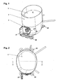
In
Der Kleinkältemittelkompressor als solcher ist wiederum an einer Kleinkältemaschine befestigt, wo er für die Wärmeabfuhr aus einem Kühlraum der Kleinkältemaschine verantwortlich ist. Ebenfalls dargestellt sind Montageflansche 20, mittels welcher der Kleinkältemittelkompressor an der Kleinkältemaschine befestigt wird sowie ein Adapterflansch 21, über welchen die Versorgung des Kleinkältemittelkompressors mit elektrischer Energie erfolgt.As such, the small refrigerant compressor is in turn attached to a small refrigeration machine, where it is responsible for the heat removal from a refrigerated space of the small refrigerator. Also shown are mounting
Wie die Darstellung zeigt, bildet der obere Bereich des Deckelteiles 1 gemeinsam mit einem am Kompressorgehäuse angeordneten ringförmigen Halteelement 2 eine Aufnahme 6, in welche ein erfindungsgemäßer Sammelbehälter 4 aus Kunststoff eingesetzt werden kann.As the illustration shows, the upper region of the
Die im Inneren des Kompressorgehäuses erzeugte Wärme wird in dieser Anordnung also sowohl über den Deckelteil 1, insbesondere Abschnitt 16 des Deckelteils 1, als auch über das Halteelement 2 auf den Sammelbehälter 4 übertragen.The heat generated in the interior of the compressor housing is thus transmitted in this arrangement both on the
Das vorzugsweise aus Stahl gefertigte Halteelement 2 kann entweder am Deckelteil oder am Basisteil 3 angeordnet sein, ist jedoch in einer bevorzugten Bauweise als abdichtendes Verbindungselement mit einem Abschnitt 17 direkt an den Berührungskanten von Deckelteil und Basisteil positioniert, wo es zumeist angeschweißt wird, um die beiden Kompressorgehäuseteile unlösbar miteinander zu verbinden (siehe auch
Die Form des Halteelementes 2 kann entsprechend der Modellierung des Kompressorgehäuses bzw. des Deckelteiles 1 variieren, wird jedoch zumeist rund oder oval ausgestaltet sein, wobei der Sammelbehälter 4 ringförmig entlang seines Umfangs umschlossen wird, um eine ausreichende Haltefunktion zu gewährleisten.The shape of the holding
In der dargestellten Bauvariante ist das Halteelement 2 zylindrisch ausgebildet mit Achse in vertikaler Richtung, relativ zur Standfläche bzw. den Montageflanschen 20 des Kompressorgehäuses gesehen, angeordnet, um solcherart leicht am Kompressorgehäuse zentriert und montiert werden zu können.In the illustrated construction variant, the holding
Unter dem Gesichtspunkt einer Materialreduktion mag es auch sinnvoll sein, den Sammelbehälter 4 durch das Halteelement 2 nicht durchgehend entlang seines Umfangs umschlossen zu halten, sondern diesen lediglich partiell zu umfassen, beispielsweise in Zinnen- oder gezahnter Form, aber auch in anderen beliebigen Formen.From the point of view of a material reduction, it may also be useful not to keep the collecting
Neben der Haltefunktion besitzt das Halteelement 2 insbesondere bei metallische Ausführung ebenfalls eine wärmeübertragende Funktion für den Sammelbehälter 4, da es infolge seiner Kühlrippenfunktion fortwährend Wärme vom Kompressorgehäuse an die Umgebung und somit auch an den angrenzenden Sammelbehälter 4 abführt und damit ein Verdunsten von im Sammelbehälter 4 befindlicher Kondensatflüssigkeit forciert. Der Sammelbehälter 4 wird also nicht nur über seinen Boden, sondern auch über seine Seitenwandungen "aufgeheizt".In addition to the holding function, the holding
Um den Kühlrippeneffekt des Halteelements 2 noch zu steigern, kann dessen Wandung, so wie in
Der erfindungsgemäß unmittelbar am Kompressorgehäuse tiefgezogene Sammelbehälter 4 ist gemäß
Montageverfahrens exakt anschmiegt, sodass zwischen Deckelteil 1 und Sammelbehälter 4 lediglich ein minimaler Luftspalt verbleibt, welcher die Verdunsterleistung und die Leistungszahl (COP) des Kleinkältemittelkompressors nur unwesentlich vermindert.Mounting method exactly conforms, so that only a minimal air gap remains between the
Die Form des Sammelbehälters 4 ist jeweils exakt an das Oberflächenprofil des Kompressorgehäuses, insbesondere jenes des Abschnitts 16 des Deckelteils 1, angepasst. Der Deckelteil 1 wird dabei zumeist eine konvexe Wölbung vorgeben, kann jedoch aus akustischen oder anderen technischen Gründen auch beliebige andere spezifische Formen aufweisen, an welche die Form des Sammelbehälters 4 zu adaptieren ist.The shape of the collecting
Der in der Folge als Rohling 4 bezeichnete Kunststoffteil, aus welchem der Sammelbehälter 4 geformt wird, kann in graduell unterschiedlich vorbearbeiteten Zuständen an der Aufnahme 6 positioniert werden.The hereinafter referred to as blank 4 plastic part from which the collecting
Beim Rohling 4 kann es sich um einen bereits mit einer Negativtoleranz serienmäßig vorgefertigten Kunststoffteil handeln, sodass dieser der Form der Aufnahme 6, in welche er zur weiteren Montage eingesetzt wird, bereits im Wesentlichen entspricht oder aber auch um einen gänzlich ungeformten Kunststoffteil, der erst während der Montage am Kompressorgehäuse seine erstmalige und endgültige Einsatzform durch ein entsprechendes Umformungsverfahren erhält. Als Beispiel für einen gänzlich ungeformten Kunststoffteil bzw. Rohling 4 sei eine Platte oder eine Folie genannt. Vor allem ein in Folienform eingesetzter Rohling 4 bietet neben seinem Vorteil besonderer Anschmiegsamkeit auch den Vorteil geringen Platzbedarfs während des Materialtransports, da die Folie als abtrennbares Endlosmaterial in aufgewickelter oder zusammengefalteter Form besonders leicht transportiert werden kann.The blank 4 can be a plastic part which is already prefabricated as standard with a negative tolerance, so that it already essentially corresponds to the shape of the
Beim Rohling 4 kann es sich ebenfalls um eine Kombination von vorgefertigten und ungeformten Kunststoffteilen handeln, beispielsweise, indem eine Folienfläche mit einem verstärkten, wulstartigen Randelement versehen ist, wobei dieses wulstartige Randelement am Halteelement 2 der Aufnahme 6 aufgesetzt wird, um während des Umformungsverfahrens ein verstärktes Widerlager zu bieten. Insbesondere kann an dieses wulstartige Randelement einen Aufnahmeschlitz 15 aufweisen, in welchen das Halteelement 2 einführbar ist.The blank 4 may also be a combination of prefabricated and unshaped plastic parts, for example, by a film surface is provided with a reinforced, bead-like edge element, said bead-like edge element on the holding
Als Werkstoffe für den Sammelbehälter 4 kommen vorzugsweise Polybuthylenterephthalat (PBT, PBTP), thermoplastisches Polyurethan (TPU), Polyethylenterephthalat (PET), Polypropylen (PP) oder Polyamid (PA) zum Einsatz, da sich diese im erfindungsgemäßen Herstellungs- bzw. Montageverfahren durch ihre besonderen plastischen Eigenschaften und ihre Festigkeitskennwerte bewähren.Polybuthylene terephthalate (PBT, PBTP), thermoplastic polyurethane (TPU), polyethylene terephthalate (PET), polypropylene (PP) or polyamide (PA) are preferably used as materials for the collecting
Im erfindungsgemäßen Verfahren wird nun der Sammelbehälter 4 als Rohling 4 in die Aufnahme 6 eingesetzt und anschließend mittels Kraftwirkung eines Druck- oder Unterdruckmittels in seine endgültige Montageform gebracht.In the method according to the invention the collecting
Als eingesetzte Druckmittel kommen sowohl flüssige oder gasförmige Medien wie etwa Pressluft oder Wasser als auch mechanische Druckmittel wie etwa Tiefziehstempel, Stößel oder Matrizen in Frage.As a pressure medium used both liquid or gaseous media such as compressed air or water as well as mechanical pressure means such as thermoforming punches, plungers or matrices in question.
Im Falle des Einsatzes flüssiger oder gasförmiger Medien als Druckmittel wird der vorgesehene Volumsbereich der Aufnahme 6 nach erfolgter Eingrenzung und Abdichtung des Druckbereichs durch geeignete Maßnahmen vorzugsweise mit heißen Gasen oder Flüssigkeiten beaufschlagt, sodass sich die Form des Sammelbehälters 4 unmittelbar und passgenau an die angrenzenden Oberflächen der Aufnahme 6, also an Kompressorgehäuse, Halteelement 2 und etwaige zusätzliche Bauteilelemente wie Schraubverbindungen oder Verrastungen anfügt.In the case of the use of liquid or gaseous media as a pressure medium of the intended volume range of the
Im Falle des Einsatzes mechanischer Druckmittel ist es vorteilhaft, diese nicht als gänzlich starre, sondern als zumindest an der Stelle ihrer Arbeitsberührungsfläche als elastische Elemente vorzusehen, wobei jedoch deren Elastizität jene des zu formenden Sammelbehältermaterials nicht überschreitet. Solcherart wird eine flexible Adaption des Sammelbehälters 4 an die Oberflächenform der Aufnahme 6 bei gleichzeitiger Sicherstellung, dass der Sammelbehälter 4 während des Tiefziehvorgangs nicht beschädigt wird, ermöglicht. Die Form des Tiefziehstempels wird dabei mit der Form des von der Aufnahme 6 umgrenzten Volumens kprrespondieren.In the case of the use of mechanical pressure means, it is advantageous to provide these not as completely rigid, but as at least at the point of their working contact surface as elastic elements, but whose elasticity does not exceed that of the collecting container material to be formed. In this way, a flexible adaptation of the collecting
Eine günstige Möglichkeit, den Sammelbehälter bzw. Rohling 4 ohne Einsatz externer Druckmittel an die Form der Aufnahme 6 anzugleichen, ist es, den Deckelteil 1 selbst als Druckmittel zu benutzen, indem zuvor der Sammelbehälter 4 als Rohling in Folienform über den offenen Querschnitt des Halteelements 2 der Aufnahme 6 gespannt wird, um dann den Deckelteil 1 so weit linear gegen die gespannte Folie zu bewegen, bis der vom Halteelement 2 umgrenzte, zur Folie weisende Abschnitt 16 des Deckelteils 1 der Folie seine vollendete Form plastisch vermittelt hat. Das Spannen der Folie am Halteelement 2 wird dabei mittels üblicher Maßnahmen zur Klemmung bewerkstelligt, beispielsweise durch Manschetten oder geeignete punktuelle Klemmung. Während der Deckelteil 1 samt Halteelement 2 als Tiefziehmatrize wirkt, erfährt er seine Führung vorzugsweise an der Innenwandung des Halteelements 2. Die formgebende Bewegung des Deckelteils 1 kann sowohl automatisiert als auch von Hand durchgeführt werden, wobei das Halteelement 2 durch eine geeignete Haltevorrichtung starr fixiert wird.A convenient way to match the sump or blank 4 without the use of external pressure means to the shape of the
Als weitere Alternative kann beim erfindungsgemäßen Verfahren ebenfalls eine Vakuumpumpe zum Einsatz kommen. Hierbei wird die Vakuumpumpe über eine entsprechende Ansaugvorrichtung an mindestens einer Öffnung der Aufnahme 6, vorzugsweise an einem mehrere Bohrungen 13 aufweisenden Abschnitt des Halteelements 2 angesetzt, um dann nach erfolgter Abdichtung des zwischen Aufnahme 6 und Sammelbehälter 4 bestehenden Volumens 7 eine Unterdruckwirkung auf dieses Volumen bzw. auf den Sammelbehälter 4 auszuüben. Auf diese Weise wird der Sammelbehälter bzw. Rohling 4 in die Form der Aufnahme 6 hineingezogen und dieser exakt angeglichen. Die Abdichtung des Unterdruckareals erfolgt dabei mittels verfahrensüblicher Maßnahmen wie etwa einem am Halteelement 2 radial umlaufenden Klemmen des Randbereichs des Sammelbehälters 4. Da das Halteelement 2 in einer bevorzugten Ausführungsart am Kompressorgehäuse angeschweißt ist, bedarf es in der Regel keiner weiteren Maßnahmen, um die Verbindungsstellen von Deckelteil 1 und Halteelement 2 abzudichten.As a further alternative, a vacuum pump can also be used in the method according to the invention. In this case, the vacuum pump is attached via a corresponding suction device to at least one opening of the
Die Umformung des Sammelbehälters bzw. Rohlings 4 erfolgt bei sämtlichen beschriebenen Verfahren zweckmäßigerweise unter externer Wärmeeinwirkung, wodurch ein einfacheres plastisches Verformen des Sammelbehälters bzw. Rohlings 4 und optimales Anschmiegen ebendieses in die Aufnahme 6 ermöglicht wird. Auf diese Weise werden wärmeübergangshindernde Luftspalten weitestgehend minimiert, wobei sogar ein restloses Ausschließen von Luftspalten zwischen dem Sammelbehälter 4 und seiner Aufnahme 6 dadurch erzielt werden kann, indem der Deckelteil 1 bzw. der Sammelbehälter 4 bis zur Erweichungstemperatur des Sammelbehälters 4 erwärmt wird, sodass dieser in seinen Randbereichen aufschmilzt, um sich mit der Oberfläche des Deckelteils 1 bleibend zu verbinden.The reshaping of the collecting container or blank 4 is expediently carried out under external heat action in all the described methods, whereby a simpler plastic deformation of the collecting container or blank 4 and optimum nestling thereof into the
Eine Befestigung des Sammelbehälters 4 in der Aufnahme 6 kann entweder durch ein passgenaues Einfügen bzw. Einpressen in ebendiese oder durch ein zusätzliches Fixieren mit geeigneten mechanischen Befestigungsteilen wie etwa Schrauben, Klemmen oder Verrastungen erfolgen. Auch der Einsatz von temperaturbeständigen Klebstoffen zu Befestigungszwecken ist möglich.An attachment of the collecting
Wie die in
Der dargestellte, dem Deckelteil 1 zugewandte Aufnahmeschlitz 15, in welchen das Halteelement 2 einführbar ist, kann gegebenenfalls auch durch Fräsen, Schlitzen oder eine andere spanlose oder spanabhebende Bearbeitungsmethode hergestellt werden, wobei auch mehrere Aufnahmeschlitze 15 im Sammelbehälter 4 vorgesehen sein können und das spanlose oder spanabhebende Bearbeiten vorzugsweise in einem verdickten Bereich der Sammelbehälterwandung stattfindet, sodass eine ausreichende Festigkeit des den Aufnahmeschlitz 15 ausbildenden Bereichs gewährleistet ist.The illustrated, the
Eine besondere Ausführungsvariante wird in
Um der Gefahr entgegenzutreten, dass sich im Sammelbehälter 4 mehr Kondensatflüssigkeit sammelt, als dieser fassen kann und diese an einen ungewünschten Ort überläuft, besitzt der Sammelbehälter 4 entsprechend der in den
Im Zusatzvolumen 9 gesammelte Kondensatflüssigkeit wird in weiterer Folge ebenfalls zum Verdunsten gebracht.In the
Im Falle einstückiger Fertigung von den das Hauptvolumen 10 und das Zusatzvolumen 9 des Sammelbehälters 4 eingrenzenden Behälterteilen ist der das Zusatzvolumen 9 eingrenzende Behälterteil bevorzugt mit einer größeren Wandstärke ausgeführt als der das Hauptvolumen 10 eingrenzende Behälterteil, um eine ausreichende Stabilität zu gewährleisten, da der das Zusatzvolumen 9 eingrenzende Behälterteil zumeist frei hängend an der Außenseite des Halteelementes 2 angeordnet ist und zudem der Kerbwirkung des Halteelementes 2 ausgesetzt ist, auf welchem er auflagert (siehe
Die das Hauptvolumen 10 und das Zusatzvolumen 9 des Sammelbehälters 4 eingrenzenden Behälterteile des Sammelbehälters 4 können jedoch auch gemäß
Um während des Tiefziehvorgangs ein Entweichen von Luft, welche sich in einem Zwischenraum 7 von Deckelteil, 1 des Kompressorgehäuses und Sammelhälter 4 befindet, zu ermöglichen, weist das Halteelement 2 Bohrungen 13 auf.In order to allow during the deep-drawing process, an escape of air, which is located in a
Claims (15)
- A compressor housing having a cover part (1) and a base part (3), which encloses a small refrigerant compressor hermetically sealed, a collection container (4) manufactured from plastic being provided on the compressor housing for evaporating condensed liquid, which is retained in a receptacle (6) implemented on the compressor housing, characterized in that the collection container (4) is a plastic part deep-drawn directly in its position in the receptacle (6) on the compressor housing.
- The compressor housing according to Claim 1, characterized in that the receptacle (6) is formed by at least one retention element (2), preferably made of metallic material, and a section (16) of the surface of the cover part (1).
- The compressor housing according to Claim 2, characterized in that the at least one retention element (2) is situated on the cover part (1), preferably on the external circumference of the cover part (1), projecting therefrom, and has a shaft-like form which is closed along its circumference and open on top.
- The compressor housing according to one of Claims 2 through 3, characterized in that the retention element (2) is implemented in toothed form on its end area facing away from the cover part (1).
- The compressor housing according to one of Claims 2 through 4, characterized in that the area of the transition from the retention element (2) to the cover part (1) is additionally provided with a coating, preferably made of plastic or lacquer.
- The compressor housing according to one of Claims 1 through 5, characterized in that the collection container (4) has, in addition to a main volume (10), an auxiliary volume (9) which is separated from the main volume (10) by a web-like wall (14).
- The compressor housing according to Claim 6, characterized in that an overflow edge (11) implemented by the web-like wall (14) is situated below the level of a horizontally projected edge of the upper boundary area of the collection container (4).
- The compressor housing according to Claim 6 or 7, characterized in that the container part (12) delimiting the auxiliary volume (9) of the collection container (4) is injected onto the peripheral end area (19) of the collection container (4) using thermoplastic methods.
- The compressor housing according to one of Claims 1 through 8, characterized in that the retention element (2) is provided with holes (13) to allow escape of air which is located in an intermediate space (7) of cover part (1) of the compressor housing and collection container (4) during the deep-drawing procedure.
- The compressor housing according to one of Claims 1 through 9, characterized in that the collection container (4) is made of polyethylene terephthalate (PET), polyamide (PA), polypropylene (PP), polybutylene terephthalate (PBT, PBTP), or thermoplastic polyurethane (TPU) which is capable of deep drawing.
- A method for producing and mounting a collection container made of plastic on a compressor housing according to one of Claims 1 through 10, characterized in that the collection container (4) is positioned as a blank (4) on the receptacle (6) provided for it on the compressor housing and subsequently is brought into its fmal mounting form using force action of a pressure or partial vacuum medium, so that at least the section of the collection container (4) located in the receptacle adapts to the shape of the receptacle (6).
- The method according to Claim 11, characterized in that the pressure medium used is a liquid or gaseous medium.
- The method according to Claim 11, characterized in that the pressure medium used is a deep-drawing plunger.
- The method according to Claim 11, characterized in that the collection container (4) is stretched as a blank (4) in film form over the open cross-section of the retention element (2) of the receptacle (6) and the cover part (1) is moved as the pressure medium far enough against the stretched blank (4) in film form that a reshaping of the blank (4) adapted to the receptacle (6) is achieved.
- The method according to one of Claims 11 through 14, characterized in that the force action of the pressure or partial vacuum medium on the collection container (4) is performed under the effect of heat.
Priority Applications (1)
| Application Number | Priority Date | Filing Date | Title |
|---|---|---|---|
| AT06830753T ATE433556T1 (en) | 2005-12-20 | 2006-12-20 | REFRIGERANT COMPRESSOR |
Applications Claiming Priority (2)
| Application Number | Priority Date | Filing Date | Title |
|---|---|---|---|
| AT0087305U AT8933U1 (en) | 2005-12-20 | 2005-12-20 | REFRIGERANT COMPRESSOR |
| PCT/EP2006/069994 WO2007071718A2 (en) | 2005-12-20 | 2006-12-20 | Coolant compressor |
Publications (2)
| Publication Number | Publication Date |
|---|---|
| EP1966551A2 EP1966551A2 (en) | 2008-09-10 |
| EP1966551B1 true EP1966551B1 (en) | 2009-06-10 |
Family
ID=37451384
Family Applications (1)
| Application Number | Title | Priority Date | Filing Date |
|---|---|---|---|
| EP06830753A Active EP1966551B1 (en) | 2005-12-20 | 2006-12-20 | Coolant compressor |
Country Status (6)
| Country | Link |
|---|---|
| US (1) | US20090165487A1 (en) |
| EP (1) | EP1966551B1 (en) |
| CN (1) | CN101341369B (en) |
| AT (2) | AT8933U1 (en) |
| DE (1) | DE502006003956D1 (en) |
| WO (1) | WO2007071718A2 (en) |
Families Citing this family (12)
| Publication number | Priority date | Publication date | Assignee | Title |
|---|---|---|---|---|
| DE102008041481A1 (en) * | 2008-08-22 | 2010-02-25 | BSH Bosch und Siemens Hausgeräte GmbH | Utilization of evaporative cooling to reduce energy consumption |
| AT10950U1 (en) * | 2008-10-21 | 2010-01-15 | Acc Austria Gmbh | REFRIGERANT COMPRESSOR |
| DE102008054936A1 (en) * | 2008-12-18 | 2010-06-24 | BSH Bosch und Siemens Hausgeräte GmbH | The refrigerator |
| JP2011149393A (en) * | 2010-01-25 | 2011-08-04 | Sanden Corp | Fluid machine |
| DE102011084717A1 (en) * | 2011-10-18 | 2013-04-18 | BSH Bosch und Siemens Hausgeräte GmbH | Refrigeration unit with evaporation tray and heater for evaporation promotion |
| CN102338531B (en) * | 2011-11-09 | 2014-01-15 | 合肥美的电冰箱有限公司 | Refrigerator |
| CN102419048B (en) * | 2011-11-09 | 2014-01-15 | 合肥美的电冰箱有限公司 | Refrigerator |
| CN104101163A (en) * | 2014-06-24 | 2014-10-15 | 滁州富达机械电子有限公司 | Water cooling machine with compressor water pan |
| US10563888B2 (en) * | 2017-06-26 | 2020-02-18 | Therma-Stor LLC | Water reservoir for a portable dehumidifier |
| WO2021081610A1 (en) * | 2019-11-01 | 2021-05-06 | Embraco Indústria De Compressores E Soluções Em Refrigeração Ltda. | Arrangement for supporting compressor in a refrigeration equipment |
| WO2021081609A1 (en) * | 2019-11-01 | 2021-05-06 | Embraco Indústria De Compressores E Soluções Em Refrigeração Ltda. | Arrangement for supporting compressor in a refrigeration equipment |
| WO2021081608A1 (en) * | 2019-11-01 | 2021-05-06 | Embraco Indústria De Compressores E Soluções Em Refrigeração Ltda. | Arrangement for supporting compressor in a refrigeration equipment |
Family Cites Families (10)
| Publication number | Priority date | Publication date | Assignee | Title |
|---|---|---|---|---|
| US2315222A (en) | 1939-04-25 | 1943-03-30 | Nash Kelvinator Corp | Refrigerating apparatus |
| US2758449A (en) * | 1955-02-18 | 1956-08-14 | Whirlpool Seeger Corp | Horizontal blower type refrigerated cabinet |
| US2909907A (en) * | 1958-11-25 | 1959-10-27 | Whirlpool Co | Refrigerating apparatus with hot gas defrost means |
| AT324370B (en) | 1973-07-10 | 1975-08-25 | Bosch Hausgeraete Gmbh | EVUMINATION DEVICE FOR MELT WATER, IN PARTICULAR FOR PERIODICALLY DEFROSTABLE COOLING OR FREEZERS |
| NZ286458A (en) * | 1996-04-26 | 1999-01-28 | Fisher & Paykel | Evaporation tray to catch defrost water from refrigerator, bottom consists of flexible membrane |
| NO307162B1 (en) | 1998-05-18 | 2000-02-21 | Ewos Innovation As | Process and plant for drying of divided / pelleted material, especially animal and / or vegetable feed, foodstuff etc. |
| DE19855504A1 (en) * | 1998-12-01 | 2000-06-08 | Bsh Bosch Siemens Hausgeraete | Refrigeration device has condensed water collection pan with flexurally slack base that can come into thermally conducting contact with compressor housing, at least in some sections |
| DE19956995A1 (en) * | 1999-11-26 | 2001-05-31 | Bsh Bosch Siemens Hausgeraete | Refrigerator has thermally insulated housing, door, machine volume, condensed water collection container with base and holding section connected together by variable height side wall |
| DE20209839U1 (en) * | 2002-06-25 | 2002-09-12 | Bsh Bosch Siemens Hausgeraete | Compressor evaporation tray assembly |
| DE10322681A1 (en) * | 2003-05-20 | 2004-12-09 | BSH Bosch und Siemens Hausgeräte GmbH | Increase in the evaporation performance through the compressor capsule as the evaporation tray bottom |
-
2005
- 2005-12-20 AT AT0087305U patent/AT8933U1/en not_active IP Right Cessation
-
2006
- 2006-12-20 US US12/086,440 patent/US20090165487A1/en not_active Abandoned
- 2006-12-20 EP EP06830753A patent/EP1966551B1/en active Active
- 2006-12-20 DE DE502006003956T patent/DE502006003956D1/en active Active
- 2006-12-20 AT AT06830753T patent/ATE433556T1/en not_active IP Right Cessation
- 2006-12-20 WO PCT/EP2006/069994 patent/WO2007071718A2/en active Application Filing
- 2006-12-20 CN CN2006800483053A patent/CN101341369B/en active Active
Also Published As
| Publication number | Publication date |
|---|---|
| WO2007071718A3 (en) | 2007-09-07 |
| DE502006003956D1 (en) | 2009-07-23 |
| CN101341369B (en) | 2011-01-12 |
| ATE433556T1 (en) | 2009-06-15 |
| AT8933U1 (en) | 2007-02-15 |
| CN101341369A (en) | 2009-01-07 |
| US20090165487A1 (en) | 2009-07-02 |
| EP1966551A2 (en) | 2008-09-10 |
| WO2007071718A2 (en) | 2007-06-28 |
Similar Documents
| Publication | Publication Date | Title |
|---|---|---|
| EP1966551B1 (en) | Coolant compressor | |
| EP2936012B1 (en) | Wall for a household refrigeration appliance comprising a single-piece support frame for an insulating body and household refrigeration device | |
| EP2059738B1 (en) | Refrigerator with a pressure-compensation valve | |
| WO2014095528A1 (en) | Support frame for an insulating body, with a seal on the inner wall and household refrigerating appliance | |
| DE19931170A1 (en) | Heat-insulating wall such as a refrigerator housing or a refrigerator door | |
| DE10145140A1 (en) | Housing for a refrigerator | |
| DE102009002209A1 (en) | Ice pressure receiver i.e. tank, for storing freezer reduction agent i.e. urea-water-solution, in vehicle, has reversible ice pressure compensation elements assigned to cup-shaped input unit and loaded by supporting body | |
| EP2906888B1 (en) | Refrigerator with built-in part | |
| EP2338014B1 (en) | Housing of a coolant compressor with evaporator shell | |
| DE102008024670B4 (en) | A method of assembling a cylinder assembly of a hermetically sealed refrigerant compressor assembly and a hermetic refrigerant compressor assembly | |
| EP2463227A1 (en) | Hydraulic tank for an industrial truck | |
| DE102010040250A1 (en) | Refrigerating appliance, in particular household refrigerating appliance | |
| DE19855504A1 (en) | Refrigeration device has condensed water collection pan with flexurally slack base that can come into thermally conducting contact with compressor housing, at least in some sections | |
| DE102010039743A1 (en) | Refrigerating appliance, in particular household refrigerating appliance | |
| EP2144020A2 (en) | Compressor and evaporation tray for a refrigeration device | |
| EP1537373B1 (en) | Refrigerant condenser, especially for motor vehicle air conditioning installations | |
| EP1890102A1 (en) | Domed header plate for the tank of a heat exchanger | |
| AT9772U1 (en) | REFRIGERANT COMPRESSOR | |
| DE102017214239A1 (en) | The refrigerator | |
| DE102008058808A1 (en) | Heat exchanger assembly i.e. refrigerant condenser assembly, for motor vehicle air conditioning system, has connection formed by soldering for connection of separate tubular components of collector | |
| AT7706U1 (en) | COMPRESSOR WITH INTEGRATED VERDUNSTERSCHALE | |
| DE10317459B4 (en) | Refrigerant compressor | |
| WO2023031396A1 (en) | Housing assembly | |
| EP1559978A2 (en) | Refrigerator and/or freezing apparatus | |
| DE102014215642A1 (en) | pumping device |
Legal Events
| Date | Code | Title | Description |
|---|---|---|---|
| PUAI | Public reference made under article 153(3) epc to a published international application that has entered the european phase |
Free format text: ORIGINAL CODE: 0009012 |
|
| 17P | Request for examination filed |
Effective date: 20080717 |
|
| AK | Designated contracting states |
Kind code of ref document: A2 Designated state(s): AT BE BG CH CY CZ DE DK EE ES FI FR GB GR HU IE IS IT LI LT LU LV MC NL PL PT RO SE SI SK TR |
|
| GRAP | Despatch of communication of intention to grant a patent |
Free format text: ORIGINAL CODE: EPIDOSNIGR1 |
|
| GRAS | Grant fee paid |
Free format text: ORIGINAL CODE: EPIDOSNIGR3 |
|
| GRAA | (expected) grant |
Free format text: ORIGINAL CODE: 0009210 |
|
| AK | Designated contracting states |
Kind code of ref document: B1 Designated state(s): AT BE BG CH CY CZ DE DK EE ES FI FR GB GR HU IE IS IT LI LT LU LV MC NL PL PT RO SE SI SK TR |
|
| REG | Reference to a national code |
Ref country code: GB Ref legal event code: FG4D Free format text: NOT ENGLISH |
|
| REG | Reference to a national code |
Ref country code: CH Ref legal event code: EP |
|
| REG | Reference to a national code |
Ref country code: IE Ref legal event code: FG4D Free format text: LANGUAGE OF EP DOCUMENT: GERMAN |
|
| REF | Corresponds to: |
Ref document number: 502006003956 Country of ref document: DE Date of ref document: 20090723 Kind code of ref document: P |
|
| PG25 | Lapsed in a contracting state [announced via postgrant information from national office to epo] |
Ref country code: FI Free format text: LAPSE BECAUSE OF FAILURE TO SUBMIT A TRANSLATION OF THE DESCRIPTION OR TO PAY THE FEE WITHIN THE PRESCRIBED TIME-LIMIT Effective date: 20090610 Ref country code: LT Free format text: LAPSE BECAUSE OF FAILURE TO SUBMIT A TRANSLATION OF THE DESCRIPTION OR TO PAY THE FEE WITHIN THE PRESCRIBED TIME-LIMIT Effective date: 20090610 |
|
| NLV1 | Nl: lapsed or annulled due to failure to fulfill the requirements of art. 29p and 29m of the patents act | ||
| PG25 | Lapsed in a contracting state [announced via postgrant information from national office to epo] |
Ref country code: SE Free format text: LAPSE BECAUSE OF FAILURE TO SUBMIT A TRANSLATION OF THE DESCRIPTION OR TO PAY THE FEE WITHIN THE PRESCRIBED TIME-LIMIT Effective date: 20090910 Ref country code: SI Free format text: LAPSE BECAUSE OF FAILURE TO SUBMIT A TRANSLATION OF THE DESCRIPTION OR TO PAY THE FEE WITHIN THE PRESCRIBED TIME-LIMIT Effective date: 20090610 Ref country code: PL Free format text: LAPSE BECAUSE OF FAILURE TO SUBMIT A TRANSLATION OF THE DESCRIPTION OR TO PAY THE FEE WITHIN THE PRESCRIBED TIME-LIMIT Effective date: 20090610 Ref country code: LV Free format text: LAPSE BECAUSE OF FAILURE TO SUBMIT A TRANSLATION OF THE DESCRIPTION OR TO PAY THE FEE WITHIN THE PRESCRIBED TIME-LIMIT Effective date: 20090610 Ref country code: NL Free format text: LAPSE BECAUSE OF FAILURE TO SUBMIT A TRANSLATION OF THE DESCRIPTION OR TO PAY THE FEE WITHIN THE PRESCRIBED TIME-LIMIT Effective date: 20090610 |
|
| REG | Reference to a national code |
Ref country code: IE Ref legal event code: FD4D |
|
| PG25 | Lapsed in a contracting state [announced via postgrant information from national office to epo] |
Ref country code: IE Free format text: LAPSE BECAUSE OF FAILURE TO SUBMIT A TRANSLATION OF THE DESCRIPTION OR TO PAY THE FEE WITHIN THE PRESCRIBED TIME-LIMIT Effective date: 20090610 Ref country code: RO Free format text: LAPSE BECAUSE OF FAILURE TO SUBMIT A TRANSLATION OF THE DESCRIPTION OR TO PAY THE FEE WITHIN THE PRESCRIBED TIME-LIMIT Effective date: 20090610 Ref country code: ES Free format text: LAPSE BECAUSE OF FAILURE TO SUBMIT A TRANSLATION OF THE DESCRIPTION OR TO PAY THE FEE WITHIN THE PRESCRIBED TIME-LIMIT Effective date: 20090921 Ref country code: IS Free format text: LAPSE BECAUSE OF FAILURE TO SUBMIT A TRANSLATION OF THE DESCRIPTION OR TO PAY THE FEE WITHIN THE PRESCRIBED TIME-LIMIT Effective date: 20091010 Ref country code: EE Free format text: LAPSE BECAUSE OF FAILURE TO SUBMIT A TRANSLATION OF THE DESCRIPTION OR TO PAY THE FEE WITHIN THE PRESCRIBED TIME-LIMIT Effective date: 20090610 Ref country code: CZ Free format text: LAPSE BECAUSE OF FAILURE TO SUBMIT A TRANSLATION OF THE DESCRIPTION OR TO PAY THE FEE WITHIN THE PRESCRIBED TIME-LIMIT Effective date: 20090610 |
|
| PG25 | Lapsed in a contracting state [announced via postgrant information from national office to epo] |
Ref country code: SK Free format text: LAPSE BECAUSE OF FAILURE TO SUBMIT A TRANSLATION OF THE DESCRIPTION OR TO PAY THE FEE WITHIN THE PRESCRIBED TIME-LIMIT Effective date: 20090610 |
|
| PG25 | Lapsed in a contracting state [announced via postgrant information from national office to epo] |
Ref country code: BG Free format text: LAPSE BECAUSE OF FAILURE TO SUBMIT A TRANSLATION OF THE DESCRIPTION OR TO PAY THE FEE WITHIN THE PRESCRIBED TIME-LIMIT Effective date: 20090910 Ref country code: PT Free format text: LAPSE BECAUSE OF FAILURE TO SUBMIT A TRANSLATION OF THE DESCRIPTION OR TO PAY THE FEE WITHIN THE PRESCRIBED TIME-LIMIT Effective date: 20091010 |
|
| PLBE | No opposition filed within time limit |
Free format text: ORIGINAL CODE: 0009261 |
|
| STAA | Information on the status of an ep patent application or granted ep patent |
Free format text: STATUS: NO OPPOSITION FILED WITHIN TIME LIMIT |
|
| PG25 | Lapsed in a contracting state [announced via postgrant information from national office to epo] |
Ref country code: DK Free format text: LAPSE BECAUSE OF FAILURE TO SUBMIT A TRANSLATION OF THE DESCRIPTION OR TO PAY THE FEE WITHIN THE PRESCRIBED TIME-LIMIT Effective date: 20090610 |
|
| 26N | No opposition filed |
Effective date: 20100311 |
|
| BERE | Be: lapsed |
Owner name: ACC AUSTRIA GMBH Effective date: 20091231 |
|
| PG25 | Lapsed in a contracting state [announced via postgrant information from national office to epo] |
Ref country code: MC Free format text: LAPSE BECAUSE OF NON-PAYMENT OF DUE FEES Effective date: 20100701 |
|
| REG | Reference to a national code |
Ref country code: FR Ref legal event code: ST Effective date: 20100831 |
|
| PG25 | Lapsed in a contracting state [announced via postgrant information from national office to epo] |
Ref country code: FR Free format text: LAPSE BECAUSE OF NON-PAYMENT OF DUE FEES Effective date: 20091231 Ref country code: GR Free format text: LAPSE BECAUSE OF FAILURE TO SUBMIT A TRANSLATION OF THE DESCRIPTION OR TO PAY THE FEE WITHIN THE PRESCRIBED TIME-LIMIT Effective date: 20090911 Ref country code: BE Free format text: LAPSE BECAUSE OF NON-PAYMENT OF DUE FEES Effective date: 20091231 |
|
| PG25 | Lapsed in a contracting state [announced via postgrant information from national office to epo] |
Ref country code: IT Free format text: LAPSE BECAUSE OF FAILURE TO SUBMIT A TRANSLATION OF THE DESCRIPTION OR TO PAY THE FEE WITHIN THE PRESCRIBED TIME-LIMIT Effective date: 20090610 |
|
| PG25 | Lapsed in a contracting state [announced via postgrant information from national office to epo] |
Ref country code: LU Free format text: LAPSE BECAUSE OF NON-PAYMENT OF DUE FEES Effective date: 20091220 |
|
| PG25 | Lapsed in a contracting state [announced via postgrant information from national office to epo] |
Ref country code: AT Free format text: LAPSE BECAUSE OF NON-PAYMENT OF DUE FEES Effective date: 20091220 |
|
| PG25 | Lapsed in a contracting state [announced via postgrant information from national office to epo] |
Ref country code: HU Free format text: LAPSE BECAUSE OF FAILURE TO SUBMIT A TRANSLATION OF THE DESCRIPTION OR TO PAY THE FEE WITHIN THE PRESCRIBED TIME-LIMIT Effective date: 20091211 |
|
| REG | Reference to a national code |
Ref country code: CH Ref legal event code: PL |
|
| GBPC | Gb: european patent ceased through non-payment of renewal fee |
Effective date: 20101220 |
|
| PG25 | Lapsed in a contracting state [announced via postgrant information from national office to epo] |
Ref country code: TR Free format text: LAPSE BECAUSE OF FAILURE TO SUBMIT A TRANSLATION OF THE DESCRIPTION OR TO PAY THE FEE WITHIN THE PRESCRIBED TIME-LIMIT Effective date: 20090610 |
|
| PG25 | Lapsed in a contracting state [announced via postgrant information from national office to epo] |
Ref country code: CY Free format text: LAPSE BECAUSE OF FAILURE TO SUBMIT A TRANSLATION OF THE DESCRIPTION OR TO PAY THE FEE WITHIN THE PRESCRIBED TIME-LIMIT Effective date: 20090610 |
|
| PG25 | Lapsed in a contracting state [announced via postgrant information from national office to epo] |
Ref country code: CH Free format text: LAPSE BECAUSE OF NON-PAYMENT OF DUE FEES Effective date: 20101231 Ref country code: LI Free format text: LAPSE BECAUSE OF NON-PAYMENT OF DUE FEES Effective date: 20101231 |
|
| PG25 | Lapsed in a contracting state [announced via postgrant information from national office to epo] |
Ref country code: GB Free format text: LAPSE BECAUSE OF NON-PAYMENT OF DUE FEES Effective date: 20101220 |
|
| REG | Reference to a national code |
Ref country code: DE Ref legal event code: R081 Ref document number: 502006003956 Country of ref document: DE Owner name: SECOP AUSTRIA GMBH, AT Free format text: FORMER OWNER: ACC AUSTRIA GMBH, FUERSTENFELD, AT Effective date: 20140312 Ref country code: DE Ref legal event code: R081 Ref document number: 502006003956 Country of ref document: DE Owner name: SECOP GMBH, DE Free format text: FORMER OWNER: ACC AUSTRIA GMBH, FUERSTENFELD, AT Effective date: 20140312 |
|
| REG | Reference to a national code |
Ref country code: DE Ref legal event code: R082 Ref document number: 502006003956 Country of ref document: DE Representative=s name: KUHNEN & WACKER PATENT- UND RECHTSANWALTSBUERO, DE Ref document number: 502006003956 Country of ref document: DE |
|
| REG | Reference to a national code |
Ref country code: DE Ref legal event code: R082 Ref document number: 502006003956 Country of ref document: DE Representative=s name: KUHNEN & WACKER PATENT- UND RECHTSANWALTSBUERO, DE Ref country code: DE Ref legal event code: R081 Ref document number: 502006003956 Country of ref document: DE Owner name: SECOP GMBH, DE Free format text: FORMER OWNER: SECOP AUSTRIA GMBH, FUERSTENFELD, AT |
|
| PGFP | Annual fee paid to national office [announced via postgrant information from national office to epo] |
Ref country code: DE Payment date: 20221227 Year of fee payment: 17 |
|
| P01 | Opt-out of the competence of the unified patent court (upc) registered |
Effective date: 20230517 |