EP2338014B1 - Housing of a coolant compressor with evaporator shell - Google Patents
Housing of a coolant compressor with evaporator shell Download PDFInfo
- Publication number
- EP2338014B1 EP2338014B1 EP09740307.5A EP09740307A EP2338014B1 EP 2338014 B1 EP2338014 B1 EP 2338014B1 EP 09740307 A EP09740307 A EP 09740307A EP 2338014 B1 EP2338014 B1 EP 2338014B1
- Authority
- EP
- European Patent Office
- Prior art keywords
- housing
- wall
- damping element
- evaporator shell
- shell according
- Prior art date
- Legal status (The legal status is an assumption and is not a legal conclusion. Google has not performed a legal analysis and makes no representation as to the accuracy of the status listed.)
- Active
Links
- 239000002826 coolant Substances 0.000 title claims 2
- 238000013016 damping Methods 0.000 claims description 114
- 239000002184 metal Substances 0.000 claims description 11
- 229910052751 metal Inorganic materials 0.000 claims description 11
- 229920001971 elastomer Polymers 0.000 claims description 9
- 239000004033 plastic Substances 0.000 claims description 9
- 229920003023 plastic Polymers 0.000 claims description 9
- 239000000463 material Substances 0.000 claims description 7
- 239000000806 elastomer Substances 0.000 claims description 6
- 239000002131 composite material Substances 0.000 claims description 5
- 229920000034 Plastomer Polymers 0.000 claims description 4
- 150000002739 metals Chemical class 0.000 claims description 2
- 239000003507 refrigerant Substances 0.000 description 9
- 239000007788 liquid Substances 0.000 description 7
- 239000000853 adhesive Substances 0.000 description 4
- 230000001070 adhesive effect Effects 0.000 description 4
- 230000005855 radiation Effects 0.000 description 4
- 238000007789 sealing Methods 0.000 description 4
- 239000010410 layer Substances 0.000 description 3
- 238000000034 method Methods 0.000 description 3
- 239000012790 adhesive layer Substances 0.000 description 2
- 238000010586 diagram Methods 0.000 description 2
- 238000005516 engineering process Methods 0.000 description 2
- 238000001704 evaporation Methods 0.000 description 2
- 230000008020 evaporation Effects 0.000 description 2
- 238000004519 manufacturing process Methods 0.000 description 2
- 238000005057 refrigeration Methods 0.000 description 2
- 229910000831 Steel Inorganic materials 0.000 description 1
- 230000001680 brushing effect Effects 0.000 description 1
- 238000010276 construction Methods 0.000 description 1
- 238000001816 cooling Methods 0.000 description 1
- 239000010432 diamond Substances 0.000 description 1
- 238000007598 dipping method Methods 0.000 description 1
- 230000000694 effects Effects 0.000 description 1
- 238000001125 extrusion Methods 0.000 description 1
- 239000011888 foil Substances 0.000 description 1
- 229920002635 polyurethane Polymers 0.000 description 1
- 239000004814 polyurethane Substances 0.000 description 1
- 238000001228 spectrum Methods 0.000 description 1
- 238000005507 spraying Methods 0.000 description 1
- 239000010959 steel Substances 0.000 description 1
- 239000003351 stiffener Substances 0.000 description 1
- 229920001169 thermoplastic Polymers 0.000 description 1
- 229920002725 thermoplastic elastomer Polymers 0.000 description 1
- 239000004416 thermosoftening plastic Substances 0.000 description 1
- 238000003466 welding Methods 0.000 description 1
Images


Classifications
-
- F—MECHANICAL ENGINEERING; LIGHTING; HEATING; WEAPONS; BLASTING
- F04—POSITIVE - DISPLACEMENT MACHINES FOR LIQUIDS; PUMPS FOR LIQUIDS OR ELASTIC FLUIDS
- F04B—POSITIVE-DISPLACEMENT MACHINES FOR LIQUIDS; PUMPS
- F04B39/00—Component parts, details, or accessories, of pumps or pumping systems specially adapted for elastic fluids, not otherwise provided for in, or of interest apart from, groups F04B25/00 - F04B37/00
- F04B39/12—Casings; Cylinders; Cylinder heads; Fluid connections
- F04B39/121—Casings
-
- F—MECHANICAL ENGINEERING; LIGHTING; HEATING; WEAPONS; BLASTING
- F25—REFRIGERATION OR COOLING; COMBINED HEATING AND REFRIGERATION SYSTEMS; HEAT PUMP SYSTEMS; MANUFACTURE OR STORAGE OF ICE; LIQUEFACTION SOLIDIFICATION OF GASES
- F25D—REFRIGERATORS; COLD ROOMS; ICE-BOXES; COOLING OR FREEZING APPARATUS NOT OTHERWISE PROVIDED FOR
- F25D21/00—Defrosting; Preventing frosting; Removing condensed or defrost water
- F25D21/14—Collecting or removing condensed and defrost water; Drip trays
-
- F—MECHANICAL ENGINEERING; LIGHTING; HEATING; WEAPONS; BLASTING
- F25—REFRIGERATION OR COOLING; COMBINED HEATING AND REFRIGERATION SYSTEMS; HEAT PUMP SYSTEMS; MANUFACTURE OR STORAGE OF ICE; LIQUEFACTION SOLIDIFICATION OF GASES
- F25B—REFRIGERATION MACHINES, PLANTS OR SYSTEMS; COMBINED HEATING AND REFRIGERATION SYSTEMS; HEAT PUMP SYSTEMS
- F25B2500/00—Problems to be solved
- F25B2500/12—Sound
-
- F—MECHANICAL ENGINEERING; LIGHTING; HEATING; WEAPONS; BLASTING
- F25—REFRIGERATION OR COOLING; COMBINED HEATING AND REFRIGERATION SYSTEMS; HEAT PUMP SYSTEMS; MANUFACTURE OR STORAGE OF ICE; LIQUEFACTION SOLIDIFICATION OF GASES
- F25D—REFRIGERATORS; COLD ROOMS; ICE-BOXES; COOLING OR FREEZING APPARATUS NOT OTHERWISE PROVIDED FOR
- F25D2321/00—Details or arrangements for defrosting; Preventing frosting; Removing condensed or defrost water, not provided for in other groups of this subclass
- F25D2321/14—Collecting condense or defrost water; Removing condense or defrost water
- F25D2321/141—Removal by evaporation
- F25D2321/1411—Removal by evaporation using compressor heat
-
- F—MECHANICAL ENGINEERING; LIGHTING; HEATING; WEAPONS; BLASTING
- F25—REFRIGERATION OR COOLING; COMBINED HEATING AND REFRIGERATION SYSTEMS; HEAT PUMP SYSTEMS; MANUFACTURE OR STORAGE OF ICE; LIQUEFACTION SOLIDIFICATION OF GASES
- F25D—REFRIGERATORS; COLD ROOMS; ICE-BOXES; COOLING OR FREEZING APPARATUS NOT OTHERWISE PROVIDED FOR
- F25D2321/00—Details or arrangements for defrosting; Preventing frosting; Removing condensed or defrost water, not provided for in other groups of this subclass
- F25D2321/14—Collecting condense or defrost water; Removing condense or defrost water
- F25D2321/144—Collecting condense or defrost water; Removing condense or defrost water characterised by the construction of drip water collection pans
- F25D2321/1442—Collecting condense or defrost water; Removing condense or defrost water characterised by the construction of drip water collection pans outside a refrigerator
-
- Y—GENERAL TAGGING OF NEW TECHNOLOGICAL DEVELOPMENTS; GENERAL TAGGING OF CROSS-SECTIONAL TECHNOLOGIES SPANNING OVER SEVERAL SECTIONS OF THE IPC; TECHNICAL SUBJECTS COVERED BY FORMER USPC CROSS-REFERENCE ART COLLECTIONS [XRACs] AND DIGESTS
- Y10—TECHNICAL SUBJECTS COVERED BY FORMER USPC
- Y10T—TECHNICAL SUBJECTS COVERED BY FORMER US CLASSIFICATION
- Y10T29/00—Metal working
- Y10T29/49—Method of mechanical manufacture
- Y10T29/49229—Prime mover or fluid pump making
- Y10T29/49236—Fluid pump or compressor making
Definitions
- the present invention relates to a housing of a refrigerant compressor with a Verdunsterschale, wherein the Verdunsterschale is at least formed by a directly and tightly attached to the housing, a circumferential line of the housing wall of metal and at least one lying within the wall part surface of the housing and at the wall is secured at a distance from the housing at least one damping element for damping the vibrations transmitted from the housing to the wall, according to the preamble of claim 1.
- Small refrigerant compressors are mainly used in the domestic balance area. They are usually located at the back of a refrigerator and connected to these and serve to compress a circulating refrigerant, whereby heat is removed from the refrigerator of the refrigerator and discharged to the environment.
- the refrigerant compressor comprising a hermetically sealed compressor housing has an electric motor which drives a piston oscillating in a cylinder for compressing the refrigerant via a crankshaft.
- the compressor housing consists of a cover part and a Base part, wherein supply and discharge lines are provided, which lead into the compressor housing and out of this, to convey the refrigerant to the cylinder and from there back into the cooling circuit.
- the collecting container is arranged in a vicinity of the compressor housing of the refrigerant compressor, since this represents a heat source and favors the evaporation of the collected liquid.
- the prior art collecting container are known, for example from the AT 7,706 U1 , where inter alia metallic boundary walls are provided which tightly surround the compressor housing along a circumferential line of the compressor housing and form an upwardly open container.
- the boundary walls are either made in one piece with a housing part or fixed by adhesive, screws, welds, flange or the like on the housing. It only has to be ensured that the contact area between the boundary wall and the housing is tight, so that the condensed liquid collected within the boundary wall remains in the evaporator shell formed by the boundary wall and the housing.
- Such a construction can dissipate the heat that is dissipated through the compressor housing. be used in almost direct manner to evaporate the condensed liquid.
- An object of the present invention is therefore to reduce the sound radiation of the compressor via the evaporator shell. This is generally possible by a change in the strength of the structure or by damping.
- the Verdunsterschale is provided in order to reduce the vibrations emanating from the compressor housing with damping elements.
- the damping elements are in this case arranged laterally on the evaporator shell.
- the walls of the evaporator shell are hollow, so that chambers or tubular damping elements are formed.
- a manufacturing technology and vibration damping technically more advantageous embodiment and arrangement of generic damping elements is sought.
- JP 2003287341 A2 relates to a refrigerator with improved heat radiation from the condenser.
- the housing of a refrigeration compressor of the refrigerator has a Verdunsterschale, which is attached to the housing, without, however, is received on vibrations of Verdunsterschale or caused thereby noise.
- this object is achieved by the characterizing features of claim 1.
- the at least one damping element surrounds the free upper edge of the wall.
- all damping elements are attached to the free edge of the wall.
- damping elements By attaching one or more damping elements at the top of the wall ensures that the wall itself is damped, which can be well stimulated to vibrate due to the free upper end.
- the damping elements cause at least a part of the vibration energy to be converted into heat.
- the at least one damping element is attached to the free upper edge of the wall.
- the at least one damping element has a groove whose width substantially corresponds to the thickness of the wall and the damping element is placed by means of this groove on the upper edge of the wall.
- one or more damping elements are made of metal. Due to their mass, metallic damping elements help to locally change the resonant frequency of the wall, so that it is no longer possible to resonate the entire wall.
- a particular embodiment of the metallic damping element is that the damping element is formed integrally with the wall.
- Another embodiment is that one or more damping elements made of plastic.
- plastic includes plastomers (thermoplastics), duromers and elastomers. Due to their elasticity they are deformed by the vibrations, which costs vibration energy, which is therefore no longer available for vibrations of the wall.
- composites having a multilayer structure wherein the individual layers of the composite in particular consist of elastomers and / or plastomers and / or duromers and / or metals and / or woods.
- elastic layers elastomer
- layers made of heavier materials metal foil
- At least one damping element may be attached such that it exerts a biasing force on the wall. If then the wall is excited to vibrate, any movement must be made against this biasing force.
- a damping element can be stretched around the wall.
- one or more damping elements can be positively and / or positively and / or materially secured to the wall.
- the positive fastening has the advantage that the damping elements can be fastened to the wall without further fastening means.
- the frictional attachment ensures a good transfer of the vibration energy from the wall to the damping element.
- damping element is releasably secured to the wall, then these damping elements can be exchanged particularly easily, it can also easily additional damping elements attached or unnecessary damping elements are removed.
- damping elements Of course, combinations of releasably and permanently attached damping elements are conceivable.
- one or more metallic damping elements could be welded to the wall, other rubber damping elements are simply plugged onto the free (upper) edge of the wall in a form-fitting manner.
- a substantially linear attachment will be useful if, for example, a heavy metallic damping element is to be fastened in a simple manner. Examples of linear fasteners can be found in Fig. 7-10 ,
- a substantially flat attachment of the damping element is useful if the damping element has a flat shape and should be well connected to the wall everywhere.
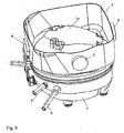
- An example of a surface attachment can be found in Fig. 6 which, however, does not represent the invention. Such an element can be glued, for example.
- a damping element is arranged along the entire circumference of the wall.
- a particularly dense and durable embodiment of the evaporator shell according to the invention is achieved by the fact that the wall of the evaporator shell is welded to the housing.
- the cross section of at least one of the damping elements can vary along the circumference of the wall.
- Fig. 1 shows a perspective view of a housing of a compressor with Verdunsterschale condensed liquid according to the prior art.
- a wall 2 made of metal, such as sheet steel, welded, which follows a circumferential line of the housing 1.
- This wall 2 forms the wall of the evaporator shell.
- the lying within the wall 2 sub-surface la of the housing forms the bottom of the evaporator shell.
- Fig. 2 is the same case as in Fig. 1 illustrated, but now with a possible embodiment of the invention: a fixed to the upper edge of the wall 2, the entire circumference of the edge covering circumferential damping element 5.
- the damping element 5 is made of an elastomer, for example made of rubber.
- Fig. 3 is a vertical section through the center of the housing 1 from Fig. 2 shown.
- the cross section of the circumferential damping element 5 becomes the section marked "B" at the upper right edge in Fig. 4 shown enlarged.
- Fig. 4 is the patch on the wall 2 circumferential damping element 5a shown in cross section. It has a circular cross-section and a radial groove which extends to about 0.7 diameter in the damping element 5.
- the groove corresponds in width to the thickness of the wall 2, so that a positive contact with the wall 2 is made possible.
- the sealing element 5a is placed on the upper edge of the wall 2.
- a circumferential damping element with rectangular cross-section 5b there are also other cross sections of the circumferential damping element 5 possible, for example, as in Fig. 5 represented, a circumferential damping element with rectangular cross-section 5b.
- the groove is arranged normal to the side surface of the rectangular cross-section, it also has a depth of about 70% of the cross-sectional height, its width is also adapted to the thickness of the wall 2, so that a positive contact between the damping element 5b and wall 2 is possible.
- Other cross sections of the damping element 5, such as triangular cross sections, are possible.
- the circumferential damping element 5, 5a, 5b is arranged on the free edge of the wall 2.
- a circumferential damping element is attached only to the inside or only on the outside of the wall 2, directly on the edge of the wall 2 subsequently or below, or embodiments where both on the inside and on the outside of the Wall 2 circumferential damping elements are arranged.
- the inner and outer damping element may be mounted at the same or different height.
- the circumferential damping element can be fixed under a bias, but it can also be fixed without bias. Is the damping element on the inside or on the Mounted outside the wall 2, the bias may be directed both inwardly and outwardly.
- the circumferential damping element on the inner and / or outer side may be formed approximately as a flat rubber band.
- Fig. 6 shows a perspective view of a non-inventive housing 1 with four lateral damping elements 6, which are mounted on the outside of the wall 2 substantially centrally in one of the four wall sections.
- the four wall sections result from the fact that the cross section of the wall 2 are not circular, but approximate the square shape.
- damping elements 6 all on the inside of the wall 2 or alternately on the inside and outside. Of course, more than four damping elements can be used.
- a single damping element 7 is mounted on the wall 2.
- the illustrated damping element 7 has the shape of a full cylinder having a groove in the radial direction to the middle of the cylinder. It would also be conceivable, however, to use a profile as in Fig. 3-5 is shown, wherein the attenuation is limited only to the region of the wall 2, on which the damping element is mounted.
- the shape of the groove is dimensioned so that the damping element 7 can be positively attached to the upper edge of the wall 2.
- the damping element 7 may be positively and / or positively and / or materially secured to the wall.
- Material for the damping element 7 are metal, plastic or composites in question.
- Fig. 8 the arrangement is off Fig. 7 added another, ie second damping element 8.
- the second illustrated damping element 8 has the shape of a full cylinder having a groove in the radial direction to the middle of the cylinder. Again, as below Fig. 7 explained, other forms conceivable.
- the shape of the groove is again dimensioned so that the damping element 8 can be positively attached to the upper edge of the wall 2.
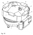
- damping elements 9, 10 can be added, as in Fig. 9 and Fig. 10 is shown.
- damping elements 7-10 can vary between the individual damping elements 7-10 and thus be better adapted to the requirements.
- the attachment of the damping elements can be done in different ways. (positive, positive and / or cohesive).
- Fig. 11 shows a diagram in which the radiated from a compressor housing sound power was measured. Shown is the third octave spectrum.
- the at least one damping element 5-10 by means of extrusion of a polymeric. Materials on the free upper edge of the wall 2, embracing this, applied. In principle, all adhesive materials are suitable for being applied directly in the area of the free upper edge of the wall 2.
- the free upper edge of the wall 2 is at least partially provided with adhesive whose mass forms one or more damping elements 5-10.
- the application of adhesive in the region of the free upper edge of the wall 2 can be carried out by means of any application method, e.g. by brushing, spraying, dipping etc.
Landscapes
- Engineering & Computer Science (AREA)
- Mechanical Engineering (AREA)
- General Engineering & Computer Science (AREA)
- Chemical & Material Sciences (AREA)
- Combustion & Propulsion (AREA)
- Physics & Mathematics (AREA)
- Thermal Sciences (AREA)
- Compressor (AREA)
- Applications Or Details Of Rotary Compressors (AREA)
Description
Die vorliegende Erfindung bezieht sich auf ein Gehäuse eines kältemittelkompressors mit einer Verdunsterschale, wobei die Verdunsterschale zumindest durch eine direkt und dicht am Gehäuse befestigte, einer Umfangslinie des Gehäuses folgende Wand aus Metall und wenigstens eine innerhalb der Wand liegende Teiloberfläche des Gehäuses gebildet wird und wobei an der Wand mit einem Abstand zum Gehäuse zumindest ein Dämpfungselement zur Dämpfung der vom Gehäuse auf die Wand übertragenen Schwingungen befestigt ist, gemäß dem Oberbegriff des Anspruchs 1.The present invention relates to a housing of a refrigerant compressor with a Verdunsterschale, wherein the Verdunsterschale is at least formed by a directly and tightly attached to the housing, a circumferential line of the housing wall of metal and at least one lying within the wall part surface of the housing and at the wall is secured at a distance from the housing at least one damping element for damping the vibrations transmitted from the housing to the wall, according to the preamble of
Kleinkältemittelkompressoren kommen vorwiegend im Hausbaltsbereich zum Einsatz. Sie sind in der Regel an der Rückseite eines Kühlschranks angeordnet und an diesen angeschlossen und dienen zur Kompression eines zirkulierenden Kältemittels, wodurch Wärme aus dem Kühlraum des Kühlschranks abtransportiert und an die Umgebung abgegeben wird.Small refrigerant compressors are mainly used in the domestic balance area. They are usually located at the back of a refrigerator and connected to these and serve to compress a circulating refrigerant, whereby heat is removed from the refrigerator of the refrigerator and discharged to the environment.
Der ein hermetisch abgedichtetes Kompressorgehäuse umfassende Kältemittelkompressor weist einen Elektromotor auf, welcher über eine Kurbelwelle einen in einem Zylinder oszillierenden Kolben zur Verdichtung des Kältemittels antreibt. Das Kompressorgehäuse besteht dabei aus einem Deckelteil und einem Basisteil, wobei Zu- und Abführleitungen vorgesehen sind, welche in das Kompressorgehäuse und aus diesem herausführen, um das Kältemittel zum Zylinder und von diesem wieder in den Kühlkreislauf zu befördern.The refrigerant compressor comprising a hermetically sealed compressor housing has an electric motor which drives a piston oscillating in a cylinder for compressing the refrigerant via a crankshaft. The compressor housing consists of a cover part and a Base part, wherein supply and discharge lines are provided, which lead into the compressor housing and out of this, to convey the refrigerant to the cylinder and from there back into the cooling circuit.
Während des Betriebes eines Kühlgerätes fällt kondensierte Flüssigkeit an, insbesondere aufgrund lokal auftretender, niedriger Temperaturen kondensierte Luftfeuchtigkeit, welche einer Sammlung in eigens dafür vorgesehenen Sammelbehältern bedarf. Diese Sammelbehälter müssen entweder regelmäßig entleert werden, oder sie gewährleisten aufgrund geeigneter Ausführung und Anordnung eine ausreichende Verdunstungsleistung, damit kondensierte Flüssigkeit wieder in den gasförmigen Zustand übergeführt wird und aus dem Bereich der Kleinkältemaschine entweichen kann.During the operation of a refrigerator condensed liquid accumulates, in particular due to locally occurring, low temperatures condensed humidity, which requires a collection in specially designated collection containers. These sumps must either be emptied regularly, or they ensure adequate evaporation performance due to suitable design and arrangement, so that condensed liquid is transferred back into the gaseous state and can escape from the field of small refrigeration machine.
Zweckmäßigerweise wird der Sammelbehälter in einer Nähe zum Kompressorgehäuse des Kältemittelkompressors angeordnet, da dieser eine Wärmequelle darstellt und das Verdunsten der aufgefangenen Flüssigkeit begünstigt. Aus dem Stand der Technik sind Sammelbehälter bekannt, beispielsweise aus der
Das direkte Befestigen der metallischen Begrenzungswand am metallischen Gehäuse (also bei einteiliger Ausführung mit einem Gehäuseteil, bei Schraub-, Schweiß- oder Flanschverbindung) hat den Nachteil, dass die Vibrationen des Kompressors auf das Gehäuse und weiter auf die Begrenzungswand übertragen werden, sodass die metallische Verdunsterschale nun ihrerseits durch ihre offene Struktur und ihre relativ große Oberfläche die Schallabstrahlung des Kompressors noch verstärkt.The direct attachment of the metallic boundary wall to the metallic housing (ie in one-piece design with a housing part in screw, welding or flange) has the disadvantage that the vibrations of the compressor are transmitted to the housing and further on the boundary wall, so that the metallic Evaporative shell now in turn reinforced by its open structure and its relatively large surface, the sound radiation of the compressor.
Eine Aufgabe der vorliegenden Erfindung ist daher, die Schallabstrahlung des Kompressors über die Verdunsterschale zu verringern. Dies ist allgemein durch eine Änderung der Strüktursteifigkeit oder durch Dämpfung möglich.An object of the present invention is therefore to reduce the sound radiation of the compressor via the evaporator shell. This is generally possible by a change in the strength of the structure or by damping.
Eine mögliche Lösung wäre, die Steifigkeit der metallischen Verdunsterschale zu erhöhen. Dies würde jedoch zusätzliche Versteifungen oder Rippen erfordern, die in einem Tiefziehprozess nicht ohne größeren Aufwand erzeugt werden können bzw. die Baugröße der Verdunsterschale derart ungünstig beeinflussen, dass viel Bauraum für wenig Fassungsvolumen benötigt wird.A possible solution would be to increase the rigidity of the metallic evaporator shell. However, this would require additional stiffeners or ribs that can not be produced in a deep drawing process without much effort or affect the size of the evaporator shell so unfavorable that much space is required for low volume.
Eine andere Lösung schlägt die
Aus der
Die aus dem Stand der Technik bekannte
Weiters ist aus dem Stand der Technik die
Es ist insbesondere eine Aufgabe der Erfindung, die Schallabstrahlung des Kompressors über die Verdunsterschale weiter zu verringern.It is a particular object of the invention to further reduce the sound radiation of the compressor via the evaporator shell.
Erfingdungsgemäß wird diese Aufgabe durch die kennzeichnenden Merkmale des Anspruchs 1 gelöst. Um die hohe Schwingungsamplitude am freien oberen Rand der Wand zu dämpfen ist vorgesehen, dass das mindestens eine Dämpfungselement den freien oberen Rand der Wand umgreift. Insbesondere kann vorgesehen werden, dass alle Dämpfungselemente am freien Rand der Wand befestigt sind.According to the invention, this object is achieved by the characterizing features of
Durch die Befestigung eines oder mehrerer Dämpfungselemente am oberen Rand der Wand wird sichergestellt, dass die Wand selbst gedämpft wird, die aufgrund des freien oberen Endes gut zum Schwingen angeregt werden kann. Die Dämpfungselemente bewirken, dass zumindest einen Teil der Vibrationsenergie in Wärme umgewandelt wird.By attaching one or more damping elements at the top of the wall ensures that the wall itself is damped, which can be well stimulated to vibrate due to the free upper end. The damping elements cause at least a part of the vibration energy to be converted into heat.
Gemäß einer bevorzugten Ausführungsvariante der Erfindung ist das mindestens eine Dämpfungselement auf den freien oberen Rand der Wand aufgesteckt.According to a preferred embodiment of the invention, the at least one damping element is attached to the free upper edge of the wall.
Gemäß einer besonders bevorzugten Ausführungsvariante der Erfindung weist das mindestens eine Dämpfungselement eine Nut auf, deren Breite im Wesentlichen der Dicke der Wand entspricht und das Dämpfungselement mittels dieser Nut auf den oberen Rand der Wand aufgesetzt ist.According to a particularly preferred embodiment of the invention, the at least one damping element has a groove whose width substantially corresponds to the thickness of the wall and the damping element is placed by means of this groove on the upper edge of the wall.
Betreffend das Material des Dämpfungselements stehen verschiedene Möglichkeiten zur Auswahl. Eine Ausführungsform besteht darin, dass ein oder mehrere Dämpfungselemente aus Metall bestehen. Metallische Dämpfungselemente helfen aufgrund ihrer Masse mit, die Resonanzfrequenz der Wand lokal zu verändern, sodass nicht mehr die gesamte Wand in Resonanz versetzt werden kann.Regarding the material of the damping element are various options to choose from. One embodiment is that one or more damping elements are made of metal. Due to their mass, metallic damping elements help to locally change the resonant frequency of the wall, so that it is no longer possible to resonate the entire wall.
Eine besondere Ausführungsform des metallischen Dämpfungselements besteht darin, dass das Dämpfungselement einstückig mit der Wand ausgebildet ist.A particular embodiment of the metallic damping element is that the damping element is formed integrally with the wall.
Eine andere Ausführungsform besteht darin, dass ein oder mehrere Dämpfungselemente aus Kunststoff bestehen. Der Begriff Kunststoff umfasst Plastomere (Thermoplaste), Duromere und Elastomere. Aufgrund ihrer Elastizität werden sie durch die Schwingungen verformt, was Vibrationsenergie kostet, die daher nicht mehr für Schwingungen der Wand zur Verfügung steht.Another embodiment is that one or more damping elements made of plastic. The term plastic includes plastomers (thermoplastics), duromers and elastomers. Due to their elasticity they are deformed by the vibrations, which costs vibration energy, which is therefore no longer available for vibrations of the wall.
Eine weitere Möglichkeit ist die Verwendung von Verbundstoffen, die einen mehrschichtigen Aufbau aufweisen, wobei die einzelnen Schichten des Verbundstoffes insbesondere aus Elastomeren und/oder Plastomeren und/oder Duromeren und/oder Metallen und/oder Hölzern bestehen. So könnten beispielsweise elastische Schichten (Elastomer) in Verbindung mit Schichten, die aus schwereren Materialien bestehen (Metallfolie), verwendet werden.Another possibility is the use of composites having a multilayer structure, wherein the individual layers of the composite in particular consist of elastomers and / or plastomers and / or duromers and / or metals and / or woods. For example, elastic layers (elastomer) could be used in conjunction with layers made of heavier materials (metal foil).
Es kann zumindest ein Dämpfungselement so befestigt werden, dass es eine Vorspannkraft auf die Wand ausübt. Wenn dann die Wand zum Schwingen angeregt wird, muss jede Bewegung gegen diese Vorspannkraft erfolgen. So kann etwa ein Dämpfungselement um die Wand herum gespannt werden.At least one damping element may be attached such that it exerts a biasing force on the wall. If then the wall is excited to vibrate, any movement must be made against this biasing force. For example, a damping element can be stretched around the wall.
Von der Art der Befestigung bieten sich folgende Möglichkeiten an: ein oder mehrere Dämpfungselemente können form- und/oder kraft- und/oder stoffschlüssig an der Wand befestigt sein. Die formschlüssige Befestigung hat den Vorteil, dass die Dämpfungselemente ohne weitere Befestigungsmittel an der Wand befestigt werden können. Die kraftschlüssige Befestigung stellt eine gute Übertragung der Schwingungsenergie von der Wand auf das Dämpfungselement sicher.From the type of attachment, the following options are available: one or more damping elements can be positively and / or positively and / or materially secured to the wall. The positive fastening has the advantage that the damping elements can be fastened to the wall without further fastening means. The frictional attachment ensures a good transfer of the vibration energy from the wall to the damping element.
Wenn vorgesehen ist, dass zumindest ein Dämpfungselement lösbar an der Wand befestigt ist, so können diese Dämpfungselemente besonders einfach ausgetauscht werden, es können auch leicht zusätzliche Dämpfungselemente befestigt oder nicht benötigte Dämpfungselemente entfernt werden.If it is provided that at least one damping element is releasably secured to the wall, then these damping elements can be exchanged particularly easily, it can also easily additional damping elements attached or unnecessary damping elements are removed.
Die Alternative, dass nämlich zumindest ein Dämpfungselement unlösbar an der Wand befestigt ist, hat den Vorteil, dass diese Elemente während langer Betriebszeiten des Kompressors dauerhaft an ihrem Platz bleiben.The alternative, namely that at least one damping element is permanently attached to the wall, has the advantage that these elements remain permanently in place during long periods of operation of the compressor.
Selbstverständlich sind auch Kombinationen von lösbar und unlösbar angebrachten Dämpfungselementen denkbar. So könnten etwa ein oder mehrere metallische Dämpfungselemente an der Wand angeschweißt werden, andere Dämpfungselemente aus Gummi werden einfach auf den freien (oberen) Rand der Wand formschlüssig aufgesteckt.Of course, combinations of releasably and permanently attached damping elements are conceivable. Thus, for example, one or more metallic damping elements could be welded to the wall, other rubber damping elements are simply plugged onto the free (upper) edge of the wall in a form-fitting manner.
Eine im Wesentlichen linienförmige Befestigung wird sich anbieten, wenn etwa ein schweres metallisches Dämpfungselement auf einfache Weise befestigt werden soll. Beispiele für linienförmige Befestigungen finden sich in
Eine im Wesentlichen flächige Befestigung des Dämpfungselements ist dann sinnvoll, wenn das Dämpfungselement eine flächige Form hat und überall gut mit der Wand verbunden sein soll. Ein Beispiel für eine flächige Befestigung findet sich in
Um eine gleichmäßige Dämpfung über den gesamten Umfang der Wand zu erreichen, kann vorgesehen werden, dass ein Dämpfungselement entlang des gesamten Umfangs der Wand angeordnet ist.In order to achieve a uniform damping over the entire circumference of the wall, it can be provided that a damping element is arranged along the entire circumference of the wall.
Eine besonders dichte und dauerhafte Ausführung der erfindungsgemäßen Verdunsterschale erreicht man dadurch, dass die Wand der Verdunsterschale am Gehäuse angeschweißt ist.A particularly dense and durable embodiment of the evaporator shell according to the invention is achieved by the fact that the wall of the evaporator shell is welded to the housing.
Gemäß einer weiteren Ausführungsform der Erfindung kann der Querschnitt zumindest eines der Dämpfungselemente entlang des Umfangs der Wand variieren.According to a further embodiment of the invention, the cross section of at least one of the damping elements can vary along the circumference of the wall.
Im Anschluss erfolgt nun eine detaillierte Beschreibung der Erfindung anhand von Zeichnungen. Dabei zeigt:
- Fig.1
- eine perspektivische Darstellung eines Gehäuses mit Verdunsterschale für kondensierte Flüssigkeit gemäß Stand der Technik
- Fig.2
- eine perspektivische Darstellung eines erfindungsgemäßen Gehäuses mit umlaufendem Dämpfungselement
- Fig.3
- ein senkrechter Schnitt durch das Gehäuse aus
Fig. 2 - Fig.4
- ein Detail aus
Fig. 3 mit Dämpfungselement - Fig.5
- ein Detail aus
Fig. 3 mit alternativem Dämpfungselement - Fig.6
- eine perspektivische Darstellung eines nicht- erfindungsgemäßen Gehäuses mit seitlichen Dämpfungselementen
- Fig.7
- eine perspektivische Darstellung eines erfindungsgemäßen Gehäuses mit einem Dämpfungselement am Rand der Wand
- Fig.8
- eine perspektivische Darstellung eines erfindungsgemäßen Gehäuses mit zwei Dämpfungselementen am Rand der Wand
- Fig. 9
- eine perspektivische Darstellung eines erfindungsgemäßen Gehäuses mit drei Dämpfungselementen am Rand der Wand
- Fig. 10
- eine perspektivische Darstellung eines erfindungsgemäßen Gehäuses mit vier Dämpfungselementen am Rand der Wand
- Fig. 11
- ein Diagramm, welches die abgestrahlte Schallleistung eines erfindungsgemäßen Gehäuses im Vergleich mit Gehäusen gemäß Stand der Technik zeigt
- Fig.1
- a perspective view of a housing with Verdunsterschale condensed liquid according to the prior art
- Fig.2
- a perspective view of a housing according to the invention with circumferential damping element
- Figure 3
- a vertical section through the housing
Fig. 2 - Figure 4
- a detail from
Fig. 3 with damping element - Figure 5
- a detail from
Fig. 3 with alternative damping element - Figure 6
- a perspective view of a non-inventive housing with lateral damping elements
- Figure 7
- a perspective view of a housing according to the invention with a damping element at the edge of the wall
- Figure 8
- a perspective view of a housing according to the invention with two damping elements at the edge of the wall
- Fig. 9
- a perspective view of a housing according to the invention with three damping elements on the edge of the wall
- Fig. 10
- a perspective view of a housing according to the invention with four damping elements at the edge of the wall
- Fig. 11
- a diagram showing the radiated sound power of a housing according to the invention in comparison with housings according to the prior art
In
In
In
Es sind aber auch andere Querschnitte des umlaufenden Dämpfungselements 5 möglich, etwa, wie in
Gemäß den
Das umlaufende Dämpfungselement kann unter einer Vorspannung befestigt werden, es kann aber auch ohne Vorspannung befestigt werden. Ist das Dämpfungselement an der Innenseite oder an der Außenseite der Wand 2 angebracht, kann die Vorspannung sowohl nach innen als auch nach außen gerichtet sein.The circumferential damping element can be fixed under a bias, but it can also be fixed without bias. Is the damping element on the inside or on the Mounted outside the
Das umlaufende Dämpfungselement an der Innen- und/oder Außenseite kann etwa als flächiges Gummiband ausgebildet sein.The circumferential damping element on the inner and / or outer side may be formed approximately as a flat rubber band.
Ähnliche Effekte lassen sich auch mit mehreren nicht umlaufenden, aber flächigen Dämpfungselementen erzielen, die um den Umfang der Wand 2 verteilt und an der Innen- und/oder Außenseite der Wand 2 angebracht sind. Auch diese können, wie oben erläutert, mit oder ohne Vorspannung montiert werden.Similar effects can also be achieved with a plurality of non-circumferential, but flat damping elements which are distributed around the circumference of the
Es wäre auch denkbar, die Dämpfungselemente 6 alle an der Innenseite der Wand 2 anzubringen oder abwechselnd an der Innen- und Außenseite. Es können natürlich auch mehr als vier Dämpfungselemente verwendet werden.It would also be conceivable to mount the damping
In
Die Form der Nut ist so bemessen, dass das Dämpfungselement 7 formschlüssig auf den oberen Rand der Wand 2 aufgesteckt werden kann. Das Dämpfungselement 7 kann form- und/oder kraft-und/oder stoffschlüssig an der Wand befestigt sein. Als Material für das Dämpfungselement 7 kommen Metall, Kunststoff oder Verbundstoffe in Frage.The shape of the groove is dimensioned so that the damping
In
Die Form der Nut ist wieder so bemessen, dass das Dämpfungselement 8 formschlüssig auf den oberen Rand der Wand 2 aufgesteckt werden kann.The shape of the groove is again dimensioned so that the damping
Ebenso können noch weitere Dämpfungselemente 9, 10 hinzugefügt werden, wie in
Abmessungen und Material der Dämpfungselemente 7-10 können zwischen den einzelnen Dämpfungselementen 7-10 variieren und somit besser an die Erfordernisse angepasst werden.Dimensions and material of the damping elements 7-10 can vary between the individual damping elements 7-10 and thus be better adapted to the requirements.
Die Befestigung der Dämpfungselemente kann auf unterschiedlichste Weise erfolgen. (kraft-, form- und/oder stoffschlüssig).The attachment of the damping elements can be done in different ways. (positive, positive and / or cohesive).
Auf der senkrechten Achse ist die abgestrahlte Schalleistung in dB(A) aufgetragen.On the vertical axis, the radiated sound power is plotted in dB (A).
Auf der waagrechten Achse sind die Frequenzen in Hz aufgetragen, der letzte Wert auf der rechten Seite (mit "S" gekennzeichnet) stellt den Summenpegel dar, und zwar für drei verschiedene Varianten:
- Gehäuse ohne Dämpfungselement (als leere Dreiecke dargestellte Messwerte),
- Gehäuse mit einem einzelnen Dämpfungselement 7, wie in
Fig. 7 (als volle Rauten dargestellte Messwerte), - Gehäuse mit einem als umlaufenden Ring ausgebildeten Dämpfungselement 5, wie in
Fig. 2 (als leere Quadrate dargestellte Messwerte).
- Housing without damping element (measured values shown as empty triangles),
- Housing with a single damping
element 7, as inFig. 7 (readings shown as full diamonds), - Housing with a designed as a circumferential
ring damping element 5, as inFig. 2 (readings shown as empty squares).
Es ist deutlich erkennbar, dass der Summenpegel des Gehäuses mit erfindungsgemäßen Dämpfungselementen niedriger ist als ohne Dämpfungselemente, wobei eine Lösung gemäß
Gemäß einem fertigungstechnisch vorteilhaften Verfahren wird das mindestens eine Dämpfungselement 5-10 mittels Extrusion eines polymeren. Materials auf dem freien oberen Rand der Wand 2, diesen umgreifend, appliziert. Grundsätzlich sind sämtliche haftfähigen Werkstoffe geeignet, um direkt im Bereich des freien oberen Randes der Wand 2 aufgebracht zu werden.According to a manufacturing technology advantageous method is the at least one damping element 5-10 by means of extrusion of a polymeric. Materials on the free upper edge of the
Es ist auch möglich, dass der freie obere Rand der Wand 2 zumindest abschnittsweise mit Klebstoff versehen wird, dessen Masse ein oder mehrere Dämpfungselemente 5-10 ausbildet. Der Klebstoffauftrag im Bereich des freien oberen Randes der Wand 2 kann mittels beliebiger Applikationsverfahren, z.B. durch Streichen, Sprühen, Tauchen etc. erfolgen.It is also possible that the free upper edge of the
Mit dem Umgreifen des freien oberen Randes der Wand 2, kann ein einseitiges Umgreifen, d.h. ein Kontaktieren bzw. Überlappen einer nach oben gewandten Stoßfläche und entweder einer Innenseite oder einer Außenseite der Wand 2 durch das Dämpfungselement 5-10 gemeint sein oder auch ein beidseitiges Umgreifen, d.h. ein Kontaktieren bzw. Überlappen der nach oben gewandten Stoßfläche und sowohl einer Innenseite als auch der Außenseite der Wand 2.By embracing the free upper edge of the
- 11
- Gehäuse des KompressorsHousing of the compressor
- 1a1a
- Boden der VerdunsterschaleBottom of the evaporator shell
- 22
- Wand der VerdunsterschaleWall of the evaporator shell
- 33
- Zuleitungsupply
- 44
- Abführleitungdischarge
- 55
- umlaufendes Dichtungselementcircumferential sealing element
- 5a5a
- umlaufendes Dichtungselement mit rundem Querschnittcircumferential sealing element with round cross section
- 5b5b
- umlaufendes Dichtungselement mit rechteckigem Querschnittcircumferential sealing element with rectangular cross section
- 66
- seitliches Dämpfungselementlateral damping element
- 77
-
erstes Dämpfungselement am Rand der Wand 2first damping element on the edge of the
wall 2 - 88th
- zweites Dämpfungselement am Rand der Wand 2second damping element on the edge of the wall. 2
- 99
-
drittes Dämpfungselement am Rand der Wand 2third damping element on the edge of the
wall 2 - 1010
-
viertes Dämpfungselement am Rand der Wand 2fourth damping element on the edge of the
wall 2
Claims (15)
- Housing of a coolant compressor having an evaporator shell, whereby the evaporator shell is formed at least by means of a wall (2) made of metal, attached directly an the housing (1), in leak-proof manner, following a circumference line of the housing (1), and at least a partial surface (la) of the housing (1) that lies within the wall (2), and whereby at least one damping element (5-10) for damping the vibrations transferred from the housing (1) to the wall (2) is attached to the wall (1), at a distance from the housing (2), characterized in that the at least one damping element (5-10) encloses the free upper edge of the wall (2).
- Housing with evaporator shell according to claim 1, characterized in that the at least one damping element (5-10) is set onto the free upper edge of the wall (2).
- Housing with evaporator shell according to claim 1, characterized in that the at least one damping element (5-10) has a groove whose width essentially corresponds to the thickness of the wall (2), and the damping element (5-10) is set onto the upper edge of the wall (2) by means of this groove
- Housing with evaporator shell according to one of claims 1 to 3, characterized in that one or more damping elements (6-10) consist of metal.
- Housing with evaporator shell according to claim 4, characterized in that the damping element is formed in one piece with the wall (2).
- Housing with evaporator shell according to one of claims 1 to 5, characterized in that one or more damping elements (5, 5a, 5b) consist of plastic (elastomer, plastomer, or duromer).
- Housing with evaporator shell according to one of claims 1 to 6, characterized in that one or more damping elements consist of composite materials that have a multi-layer structure, whereby the individual layers of the composite material particularly consist of elastomers and/or plastomers and/or duromers and/or metals and/or woods.
- Housing with evaporator shell according to claim 6 or 7, characterized in that at least one damping element (5, 5a, 5b) is attached in such a manner that it exerts a bias force an the wall (2).
- Housing with evaporator shell according to one of claims 1 to 8, characterized in that one or more damping elements (5-10) is/are attached to the wall (2) with shape fit and/or force fit and/or material fit.
- Housing with evaporator shell according to one of claims 1 to 9, characterized in that at least one damping element (5-10) is releasably attached to the wall.
- Housing with evaporator shell according to one of claims 1 to 10, characterized in that at least one damping element (5-10) is non-releasably attached to the wall.
- Housing with evaporator shell according to one of claims 1 to 11, characterized in that at least one damping element has an attachment essentially in form of a line.
- Housing with evaporator shell according to one of claims 1 to 12, characterized in that at least one damping element (5-10) has an essentially planar attachment.
- Housing with evaporator shell according to one of claims 1 to 13, characterized in that a damping element (5, 5a, 5b) is disposed along the entire circumference of the wall (2).
- Housing with evaporator shell according to one of claims 1 to 14, characterized in that the wall (2) is welded onto the housing (1).
Applications Claiming Priority (2)
| Application Number | Priority Date | Filing Date | Title |
|---|---|---|---|
| AT0060208U AT10950U1 (en) | 2008-10-21 | 2008-10-21 | REFRIGERANT COMPRESSOR |
| PCT/EP2009/063673 WO2010046343A1 (en) | 2008-10-21 | 2009-10-19 | Coolant compressor with evaporator shell |
Publications (2)
| Publication Number | Publication Date |
|---|---|
| EP2338014A1 EP2338014A1 (en) | 2011-06-29 |
| EP2338014B1 true EP2338014B1 (en) | 2017-03-22 |
Family
ID=41260048
Family Applications (1)
| Application Number | Title | Priority Date | Filing Date |
|---|---|---|---|
| EP09740307.5A Active EP2338014B1 (en) | 2008-10-21 | 2009-10-19 | Housing of a coolant compressor with evaporator shell |
Country Status (5)
| Country | Link |
|---|---|
| US (1) | US20110293446A1 (en) |
| EP (1) | EP2338014B1 (en) |
| CN (1) | CN102232170B (en) |
| AT (1) | AT10950U1 (en) |
| WO (1) | WO2010046343A1 (en) |
Families Citing this family (7)
| Publication number | Priority date | Publication date | Assignee | Title |
|---|---|---|---|---|
| DE202013004850U1 (en) * | 2013-05-27 | 2013-06-05 | Thermo Electron Led Gmbh | Laboratory centrifuge with insulated compressor |
| DE102015200394A1 (en) | 2015-01-14 | 2016-07-14 | BSH Hausgeräte GmbH | COOLING UNIT |
| CN104949421A (en) * | 2015-06-30 | 2015-09-30 | 合肥美的电冰箱有限公司 | Refrigerator |
| US11231024B2 (en) * | 2017-02-16 | 2022-01-25 | Samsung Electronics Co., Ltd. | Compressor comprising an upper shell and a lower shell wherein the upper shell comprises an upper protrusion comprising a first protrusion and a second protrusion comprising a transition and an approximately flat shape |
| CN108326517B (en) * | 2018-02-06 | 2019-11-05 | 杨益民 | A kind of manufacturing method of ice machine evaporator |
| DE102018107304A1 (en) * | 2018-03-27 | 2019-10-02 | Man Energy Solutions Se | turbocharger |
| DE102018218019A1 (en) * | 2018-10-22 | 2020-04-23 | BSH Hausgeräte GmbH | Evaporation arrangement for a refrigerator |
Citations (2)
| Publication number | Priority date | Publication date | Assignee | Title |
|---|---|---|---|---|
| US6112848A (en) * | 1998-09-23 | 2000-09-05 | Chrysler Corporation | Sound-dampened automobile interior components and methods for making same |
| JP2003287341A (en) * | 2002-03-29 | 2003-10-10 | Fujitsu General Ltd | Refrigerator |
Family Cites Families (8)
| Publication number | Priority date | Publication date | Assignee | Title |
|---|---|---|---|---|
| AT324370B (en) * | 1973-07-10 | 1975-08-25 | Bosch Hausgeraete Gmbh | EVUMINATION DEVICE FOR MELT WATER, IN PARTICULAR FOR PERIODICALLY DEFROSTABLE COOLING OR FREEZERS |
| JPS62122289U (en) * | 1986-01-27 | 1987-08-03 | ||
| JPS63122289U (en) * | 1987-02-02 | 1988-08-09 | ||
| US5699677A (en) * | 1996-11-07 | 1997-12-23 | White Consolidated Industries, Inc. | Compressor mounted drain pan utilizing polyurethane adhesive |
| KR100483556B1 (en) * | 2002-09-17 | 2005-04-15 | 삼성광주전자 주식회사 | Case for hermetic type compressor |
| AT7706U1 (en) * | 2004-05-11 | 2005-07-25 | Verdichter Oe Ges M B H | COMPRESSOR WITH INTEGRATED VERDUNSTERSCHALE |
| AT8933U1 (en) * | 2005-12-20 | 2007-02-15 | Acc Austria Gmbh | REFRIGERANT COMPRESSOR |
| BRPI0700554A (en) * | 2007-01-30 | 2008-09-16 | Whirlpool Sa | resonator arrangement for refrigeration cabinet |
-
2008
- 2008-10-21 AT AT0060208U patent/AT10950U1/en not_active IP Right Cessation
-
2009
- 2009-10-19 CN CN200980148078.5A patent/CN102232170B/en active Active
- 2009-10-19 US US12/998,436 patent/US20110293446A1/en not_active Abandoned
- 2009-10-19 EP EP09740307.5A patent/EP2338014B1/en active Active
- 2009-10-19 WO PCT/EP2009/063673 patent/WO2010046343A1/en active Application Filing
Patent Citations (2)
| Publication number | Priority date | Publication date | Assignee | Title |
|---|---|---|---|---|
| US6112848A (en) * | 1998-09-23 | 2000-09-05 | Chrysler Corporation | Sound-dampened automobile interior components and methods for making same |
| JP2003287341A (en) * | 2002-03-29 | 2003-10-10 | Fujitsu General Ltd | Refrigerator |
Also Published As
| Publication number | Publication date |
|---|---|
| AT10950U1 (en) | 2010-01-15 |
| EP2338014A1 (en) | 2011-06-29 |
| WO2010046343A1 (en) | 2010-04-29 |
| CN102232170A (en) | 2011-11-02 |
| US20110293446A1 (en) | 2011-12-01 |
| CN102232170B (en) | 2015-09-23 |
Similar Documents
| Publication | Publication Date | Title |
|---|---|---|
| EP2338014B1 (en) | Housing of a coolant compressor with evaporator shell | |
| DE2515234C3 (en) | Holder for vibration-damping attachment of a microphone inside an electrical device | |
| EP1697923B1 (en) | Component that absorbs airborne sound | |
| EP0135845B1 (en) | Means for mounting an instrument comprising two succesive supporting flanges | |
| DE69823581T2 (en) | Intermediate piece for connecting a drive assembly housing with a compressor housing | |
| DE2810059A1 (en) | MULTIPLE ARRANGEMENT OF MOTOR / COMPRESSOR UNITS FOR COOLING SYSTEMS | |
| DE102016214289A1 (en) | Vehicle, with a high-voltage storage | |
| DE102005038780A1 (en) | Linear compressor, in particular refrigerant compressor | |
| EP3542062B1 (en) | Refrigerant compressor | |
| DE102009030583A1 (en) | Fuel tank for vehicle, has tank bottom, tank walls, tank cover, opening, for filling fuel in fuel tank and opening for removing fuel from fuel tank | |
| DE4212190A1 (en) | ELASTIC STORAGE WITH A FLUID FILLING | |
| DE102005033509A1 (en) | Hydraulic engine bearing assembly e.g. for motor vehicle, is accommodated in housing shell which has fastening unit for fixing at bearing point at body side and mounting device for fixing lower bearing with spring | |
| DE3700589C2 (en) | Vibration damper | |
| WO2014060314A1 (en) | Refrigeration device comprising a fitted part | |
| DE4416449A1 (en) | Unit consisting of a hydraulic machine (hydraulic pump or hydraulic motor) and a carrier | |
| WO2011020785A1 (en) | Wheel for a rail vehicle | |
| DE102009002891A1 (en) | Piston-cylinder unit with a connecting element | |
| DE3712656C2 (en) | ||
| DE2933726A1 (en) | Vibration damper for machine part oscillating linear motion - has mass in viscoelastic liq., whose physical parameters meet specified equation | |
| DE60004525T2 (en) | SUCTION MUFFLER FOR A HERMETIC COMPRESSOR | |
| DE102009006635A1 (en) | Container wall i.e. oil sump, for motor vehicle, has decoupling element physically separating inner and outer walls from one another, where element is flat in shape and covers inner wall and/or outer wall in tight-fitting manner | |
| DE102015206117A1 (en) | Vibration damping of a drive of a heat pump of a household appliance | |
| DE3825019A1 (en) | CYLINDRICAL, ELASTIC STORAGE WITH A LIQUID FILLING | |
| DE602005004987T2 (en) | Exhaust valve for reciprocating compressor | |
| DE102015015280A1 (en) | Cross member for a vehicle frame, a vehicle frame and a vehicle comprising such a cross member |
Legal Events
| Date | Code | Title | Description |
|---|---|---|---|
| PUAI | Public reference made under article 153(3) epc to a published international application that has entered the european phase |
Free format text: ORIGINAL CODE: 0009012 |
|
| 17P | Request for examination filed |
Effective date: 20110523 |
|
| AK | Designated contracting states |
Kind code of ref document: A1 Designated state(s): AT BE BG CH CY CZ DE DK EE ES FI FR GB GR HR HU IE IS IT LI LT LU LV MC MK MT NL NO PL PT RO SE SI SK SM TR |
|
| AX | Request for extension of the european patent |
Extension state: AL BA RS |
|
| DAX | Request for extension of the european patent (deleted) | ||
| 17Q | First examination report despatched |
Effective date: 20131021 |
|
| RAP1 | Party data changed (applicant data changed or rights of an application transferred) |
Owner name: SECOP AUSTRIA GMBH |
|
| RAP1 | Party data changed (applicant data changed or rights of an application transferred) |
Owner name: SECOP AUSTRIA GMBH |
|
| RIC1 | Information provided on ipc code assigned before grant |
Ipc: F25D 21/14 20060101AFI20160204BHEP Ipc: F04B 39/12 20060101ALI20160204BHEP |
|
| GRAP | Despatch of communication of intention to grant a patent |
Free format text: ORIGINAL CODE: EPIDOSNIGR1 |
|
| INTG | Intention to grant announced |
Effective date: 20160421 |
|
| GRAJ | Information related to disapproval of communication of intention to grant by the applicant or resumption of examination proceedings by the epo deleted |
Free format text: ORIGINAL CODE: EPIDOSDIGR1 |
|
| INTC | Intention to grant announced (deleted) | ||
| GRAP | Despatch of communication of intention to grant a patent |
Free format text: ORIGINAL CODE: EPIDOSNIGR1 |
|
| INTG | Intention to grant announced |
Effective date: 20161014 |
|
| RAP1 | Party data changed (applicant data changed or rights of an application transferred) |
Owner name: SECOP GMBH |
|
| GRAS | Grant fee paid |
Free format text: ORIGINAL CODE: EPIDOSNIGR3 |
|
| GRAA | (expected) grant |
Free format text: ORIGINAL CODE: 0009210 |
|
| AK | Designated contracting states |
Kind code of ref document: B1 Designated state(s): AT BE BG CH CY CZ DE DK EE ES FI FR GB GR HR HU IE IS IT LI LT LU LV MC MK MT NL NO PL PT RO SE SI SK SM TR |
|
| REG | Reference to a national code |
Ref country code: GB Ref legal event code: FG4D Free format text: NOT ENGLISH |
|
| REG | Reference to a national code |
Ref country code: CH Ref legal event code: EP |
|
| REG | Reference to a national code |
Ref country code: AT Ref legal event code: REF Ref document number: 878195 Country of ref document: AT Kind code of ref document: T Effective date: 20170415 |
|
| REG | Reference to a national code |
Ref country code: IE Ref legal event code: FG4D Free format text: LANGUAGE OF EP DOCUMENT: GERMAN |
|
| REG | Reference to a national code |
Ref country code: DE Ref legal event code: R096 Ref document number: 502009013789 Country of ref document: DE |
|
| REG | Reference to a national code |
Ref country code: NL Ref legal event code: MP Effective date: 20170322 |
|
| PG25 | Lapsed in a contracting state [announced via postgrant information from national office to epo] |
Ref country code: NO Free format text: LAPSE BECAUSE OF FAILURE TO SUBMIT A TRANSLATION OF THE DESCRIPTION OR TO PAY THE FEE WITHIN THE PRESCRIBED TIME-LIMIT Effective date: 20170622 Ref country code: GR Free format text: LAPSE BECAUSE OF FAILURE TO SUBMIT A TRANSLATION OF THE DESCRIPTION OR TO PAY THE FEE WITHIN THE PRESCRIBED TIME-LIMIT Effective date: 20170623 Ref country code: FI Free format text: LAPSE BECAUSE OF FAILURE TO SUBMIT A TRANSLATION OF THE DESCRIPTION OR TO PAY THE FEE WITHIN THE PRESCRIBED TIME-LIMIT Effective date: 20170322 Ref country code: HR Free format text: LAPSE BECAUSE OF FAILURE TO SUBMIT A TRANSLATION OF THE DESCRIPTION OR TO PAY THE FEE WITHIN THE PRESCRIBED TIME-LIMIT Effective date: 20170322 Ref country code: LT Free format text: LAPSE BECAUSE OF FAILURE TO SUBMIT A TRANSLATION OF THE DESCRIPTION OR TO PAY THE FEE WITHIN THE PRESCRIBED TIME-LIMIT Effective date: 20170322 |
|
| REG | Reference to a national code |
Ref country code: LT Ref legal event code: MG4D |
|
| PG25 | Lapsed in a contracting state [announced via postgrant information from national office to epo] |
Ref country code: SE Free format text: LAPSE BECAUSE OF FAILURE TO SUBMIT A TRANSLATION OF THE DESCRIPTION OR TO PAY THE FEE WITHIN THE PRESCRIBED TIME-LIMIT Effective date: 20170322 Ref country code: LV Free format text: LAPSE BECAUSE OF FAILURE TO SUBMIT A TRANSLATION OF THE DESCRIPTION OR TO PAY THE FEE WITHIN THE PRESCRIBED TIME-LIMIT Effective date: 20170322 Ref country code: BG Free format text: LAPSE BECAUSE OF FAILURE TO SUBMIT A TRANSLATION OF THE DESCRIPTION OR TO PAY THE FEE WITHIN THE PRESCRIBED TIME-LIMIT Effective date: 20170622 |
|
| PG25 | Lapsed in a contracting state [announced via postgrant information from national office to epo] |
Ref country code: NL Free format text: LAPSE BECAUSE OF FAILURE TO SUBMIT A TRANSLATION OF THE DESCRIPTION OR TO PAY THE FEE WITHIN THE PRESCRIBED TIME-LIMIT Effective date: 20170322 |
|
| PG25 | Lapsed in a contracting state [announced via postgrant information from national office to epo] |
Ref country code: CZ Free format text: LAPSE BECAUSE OF FAILURE TO SUBMIT A TRANSLATION OF THE DESCRIPTION OR TO PAY THE FEE WITHIN THE PRESCRIBED TIME-LIMIT Effective date: 20170322 Ref country code: RO Free format text: LAPSE BECAUSE OF FAILURE TO SUBMIT A TRANSLATION OF THE DESCRIPTION OR TO PAY THE FEE WITHIN THE PRESCRIBED TIME-LIMIT Effective date: 20170322 Ref country code: EE Free format text: LAPSE BECAUSE OF FAILURE TO SUBMIT A TRANSLATION OF THE DESCRIPTION OR TO PAY THE FEE WITHIN THE PRESCRIBED TIME-LIMIT Effective date: 20170322 Ref country code: ES Free format text: LAPSE BECAUSE OF FAILURE TO SUBMIT A TRANSLATION OF THE DESCRIPTION OR TO PAY THE FEE WITHIN THE PRESCRIBED TIME-LIMIT Effective date: 20170322 |
|
| REG | Reference to a national code |
Ref country code: SK Ref legal event code: T3 Ref document number: E 24512 Country of ref document: SK |
|
| PG25 | Lapsed in a contracting state [announced via postgrant information from national office to epo] |
Ref country code: PL Free format text: LAPSE BECAUSE OF FAILURE TO SUBMIT A TRANSLATION OF THE DESCRIPTION OR TO PAY THE FEE WITHIN THE PRESCRIBED TIME-LIMIT Effective date: 20170322 Ref country code: PT Free format text: LAPSE BECAUSE OF FAILURE TO SUBMIT A TRANSLATION OF THE DESCRIPTION OR TO PAY THE FEE WITHIN THE PRESCRIBED TIME-LIMIT Effective date: 20170724 Ref country code: SM Free format text: LAPSE BECAUSE OF FAILURE TO SUBMIT A TRANSLATION OF THE DESCRIPTION OR TO PAY THE FEE WITHIN THE PRESCRIBED TIME-LIMIT Effective date: 20170322 Ref country code: IS Free format text: LAPSE BECAUSE OF FAILURE TO SUBMIT A TRANSLATION OF THE DESCRIPTION OR TO PAY THE FEE WITHIN THE PRESCRIBED TIME-LIMIT Effective date: 20170722 |
|
| REG | Reference to a national code |
Ref country code: DE Ref legal event code: R097 Ref document number: 502009013789 Country of ref document: DE |
|
| PLBE | No opposition filed within time limit |
Free format text: ORIGINAL CODE: 0009261 |
|
| STAA | Information on the status of an ep patent application or granted ep patent |
Free format text: STATUS: NO OPPOSITION FILED WITHIN TIME LIMIT |
|
| PG25 | Lapsed in a contracting state [announced via postgrant information from national office to epo] |
Ref country code: DK Free format text: LAPSE BECAUSE OF FAILURE TO SUBMIT A TRANSLATION OF THE DESCRIPTION OR TO PAY THE FEE WITHIN THE PRESCRIBED TIME-LIMIT Effective date: 20170322 |
|
| 26N | No opposition filed |
Effective date: 20180102 |
|
| PG25 | Lapsed in a contracting state [announced via postgrant information from national office to epo] |
Ref country code: SI Free format text: LAPSE BECAUSE OF FAILURE TO SUBMIT A TRANSLATION OF THE DESCRIPTION OR TO PAY THE FEE WITHIN THE PRESCRIBED TIME-LIMIT Effective date: 20170322 |
|
| PG25 | Lapsed in a contracting state [announced via postgrant information from national office to epo] |
Ref country code: MC Free format text: LAPSE BECAUSE OF FAILURE TO SUBMIT A TRANSLATION OF THE DESCRIPTION OR TO PAY THE FEE WITHIN THE PRESCRIBED TIME-LIMIT Effective date: 20170322 |
|
| REG | Reference to a national code |
Ref country code: CH Ref legal event code: PL |
|
| GBPC | Gb: european patent ceased through non-payment of renewal fee |
Effective date: 20171019 |
|
| REG | Reference to a national code |
Ref country code: IE Ref legal event code: MM4A |
|
| REG | Reference to a national code |
Ref country code: FR Ref legal event code: ST Effective date: 20180629 |
|
| PG25 | Lapsed in a contracting state [announced via postgrant information from national office to epo] |
Ref country code: LI Free format text: LAPSE BECAUSE OF NON-PAYMENT OF DUE FEES Effective date: 20171031 Ref country code: CH Free format text: LAPSE BECAUSE OF NON-PAYMENT OF DUE FEES Effective date: 20171031 Ref country code: GB Free format text: LAPSE BECAUSE OF NON-PAYMENT OF DUE FEES Effective date: 20171019 Ref country code: LU Free format text: LAPSE BECAUSE OF NON-PAYMENT OF DUE FEES Effective date: 20171019 |
|
| REG | Reference to a national code |
Ref country code: BE Ref legal event code: MM Effective date: 20171031 |
|
| PG25 | Lapsed in a contracting state [announced via postgrant information from national office to epo] |
Ref country code: BE Free format text: LAPSE BECAUSE OF NON-PAYMENT OF DUE FEES Effective date: 20171031 Ref country code: FR Free format text: LAPSE BECAUSE OF NON-PAYMENT OF DUE FEES Effective date: 20171031 |
|
| PG25 | Lapsed in a contracting state [announced via postgrant information from national office to epo] |
Ref country code: MT Free format text: LAPSE BECAUSE OF FAILURE TO SUBMIT A TRANSLATION OF THE DESCRIPTION OR TO PAY THE FEE WITHIN THE PRESCRIBED TIME-LIMIT Effective date: 20170322 |
|
| PG25 | Lapsed in a contracting state [announced via postgrant information from national office to epo] |
Ref country code: IE Free format text: LAPSE BECAUSE OF NON-PAYMENT OF DUE FEES Effective date: 20171019 |
|
| REG | Reference to a national code |
Ref country code: AT Ref legal event code: MM01 Ref document number: 878195 Country of ref document: AT Kind code of ref document: T Effective date: 20171019 |
|
| PG25 | Lapsed in a contracting state [announced via postgrant information from national office to epo] |
Ref country code: AT Free format text: LAPSE BECAUSE OF NON-PAYMENT OF DUE FEES Effective date: 20171019 |
|
| PG25 | Lapsed in a contracting state [announced via postgrant information from national office to epo] |
Ref country code: HU Free format text: LAPSE BECAUSE OF FAILURE TO SUBMIT A TRANSLATION OF THE DESCRIPTION OR TO PAY THE FEE WITHIN THE PRESCRIBED TIME-LIMIT; INVALID AB INITIO Effective date: 20091019 |
|
| PG25 | Lapsed in a contracting state [announced via postgrant information from national office to epo] |
Ref country code: CY Free format text: LAPSE BECAUSE OF NON-PAYMENT OF DUE FEES Effective date: 20170322 |
|
| PG25 | Lapsed in a contracting state [announced via postgrant information from national office to epo] |
Ref country code: MK Free format text: LAPSE BECAUSE OF FAILURE TO SUBMIT A TRANSLATION OF THE DESCRIPTION OR TO PAY THE FEE WITHIN THE PRESCRIBED TIME-LIMIT Effective date: 20170322 |
|
| PG25 | Lapsed in a contracting state [announced via postgrant information from national office to epo] |
Ref country code: TR Free format text: LAPSE BECAUSE OF FAILURE TO SUBMIT A TRANSLATION OF THE DESCRIPTION OR TO PAY THE FEE WITHIN THE PRESCRIBED TIME-LIMIT Effective date: 20170322 |
|
| P01 | Opt-out of the competence of the unified patent court (upc) registered |
Effective date: 20230517 |
|
| PGFP | Annual fee paid to national office [announced via postgrant information from national office to epo] |
Ref country code: SK Payment date: 20231005 Year of fee payment: 15 |
|
| PGFP | Annual fee paid to national office [announced via postgrant information from national office to epo] |
Ref country code: IT Payment date: 20231024 Year of fee payment: 15 Ref country code: DE Payment date: 20231027 Year of fee payment: 15 |