EP1965155A2 - Kühlmittelrohr für einen Kältekreislauf und Verfahren zu seiner Herstellung - Google Patents
Kühlmittelrohr für einen Kältekreislauf und Verfahren zu seiner Herstellung Download PDFInfo
- Publication number
- EP1965155A2 EP1965155A2 EP08003250A EP08003250A EP1965155A2 EP 1965155 A2 EP1965155 A2 EP 1965155A2 EP 08003250 A EP08003250 A EP 08003250A EP 08003250 A EP08003250 A EP 08003250A EP 1965155 A2 EP1965155 A2 EP 1965155A2
- Authority
- EP
- European Patent Office
- Prior art keywords
- pipe
- pipe section
- refrigerant
- section
- thickness
- Prior art date
- Legal status (The legal status is an assumption and is not a legal conclusion. Google has not performed a legal analysis and makes no representation as to the accuracy of the status listed.)
- Withdrawn
Links
Images


Classifications
-
- F—MECHANICAL ENGINEERING; LIGHTING; HEATING; WEAPONS; BLASTING
- F25—REFRIGERATION OR COOLING; COMBINED HEATING AND REFRIGERATION SYSTEMS; HEAT PUMP SYSTEMS; MANUFACTURE OR STORAGE OF ICE; LIQUEFACTION SOLIDIFICATION OF GASES
- F25B—REFRIGERATION MACHINES, PLANTS OR SYSTEMS; COMBINED HEATING AND REFRIGERATION SYSTEMS; HEAT PUMP SYSTEMS
- F25B45/00—Arrangements for charging or discharging refrigerant
-
- F—MECHANICAL ENGINEERING; LIGHTING; HEATING; WEAPONS; BLASTING
- F25—REFRIGERATION OR COOLING; COMBINED HEATING AND REFRIGERATION SYSTEMS; HEAT PUMP SYSTEMS; MANUFACTURE OR STORAGE OF ICE; LIQUEFACTION SOLIDIFICATION OF GASES
- F25B—REFRIGERATION MACHINES, PLANTS OR SYSTEMS; COMBINED HEATING AND REFRIGERATION SYSTEMS; HEAT PUMP SYSTEMS
- F25B41/00—Fluid-circulation arrangements
- F25B41/40—Fluid line arrangements
-
- F—MECHANICAL ENGINEERING; LIGHTING; HEATING; WEAPONS; BLASTING
- F25—REFRIGERATION OR COOLING; COMBINED HEATING AND REFRIGERATION SYSTEMS; HEAT PUMP SYSTEMS; MANUFACTURE OR STORAGE OF ICE; LIQUEFACTION SOLIDIFICATION OF GASES
- F25B—REFRIGERATION MACHINES, PLANTS OR SYSTEMS; COMBINED HEATING AND REFRIGERATION SYSTEMS; HEAT PUMP SYSTEMS
- F25B41/00—Fluid-circulation arrangements
-
- F—MECHANICAL ENGINEERING; LIGHTING; HEATING; WEAPONS; BLASTING
- F25—REFRIGERATION OR COOLING; COMBINED HEATING AND REFRIGERATION SYSTEMS; HEAT PUMP SYSTEMS; MANUFACTURE OR STORAGE OF ICE; LIQUEFACTION SOLIDIFICATION OF GASES
- F25B—REFRIGERATION MACHINES, PLANTS OR SYSTEMS; COMBINED HEATING AND REFRIGERATION SYSTEMS; HEAT PUMP SYSTEMS
- F25B2500/00—Problems to be solved
- F25B2500/01—Geometry problems, e.g. for reducing size
Definitions
- the present invention relates to a refrigerant pipe used for a refrigeration cycle and a manufacturing method of the same. More particularly, the present invention relates to a refrigerant pipe that is employed in a refrigeration cycle to connect components of the refrigeration cycle to each other, and a manufacturing method of the same.
- a refrigeration cycle is adopted in a refrigerator or an air conditioner to perform a cooling operation.
- a refrigeration cycle includes components, such as a compressor, a condenser, an evaporator and an expander. These components are connected to each other via refrigerant pipes so that the refrigeration cycle is performed in the form of a closed loop.
- the conventional refrigerant pipe has constant inner and outer diameters over the whole area thereof.
- Each component of the refrigeration cycle is formed with a coupling section having a substantially pipe shape such that the component can be coupled with the refrigerant pipe. Both ends of the refrigerant pipe are welded to the coupling section of the each component.
- the ends of the conventional refrigerant pipe which are welded to the coupling section of the component, are thermally deformed due to the heat generated during the welding process so that the strength of the refrigerant pipe may be lowered at the ends of the refrigerant pipe. If the ends of the refrigerant pipe have low strength, the ends of the refrigerant pipe coupled with the coupling section of the component may be broken as vibration is applied to the refrigerant pipe during the refrigeration cycle.
- a non-limiting object of the present invention is to provide a refrigerant pipe, and a manufacturing method of the same, in which each refrigerant pipe includes a main pipe section having a first and a second end, and a connection pipe section at the first end and the second end of the main pipe section configured to be connected to the components of the refrigeration cycle, wherein a thickness of the connection pipe section is larger than a thickness of the main pipe section.
- the method includes forming connection pipe sections at a first end and a second end of the refrigerant pipe such that the connection pipe sections have a thickness larger than a thickness of a main pipe section formed between the connection pipe sections, wherein the refrigerant pipe is obtained by forming a linear primary pipe having a constant thickness through a drawing process, and then forming the connection pipe sections by deforming both ends of the linear primary pipe while applying pressure lengthwise along the linear primary pipe.
- FIG. 1 is a schematic view showing the structure of a refrigeration cycle according to an exemplary embodiment of the present invention.
- the refrigeration cycle of the present invention may be employed in a refrigerator, an air conditioner, or a water purifier to perform a cooling operation.
- the refrigeration cycle includes components, such as a compressor 1, a condenser 2, an expander 3 and an evaporator 4.
- a plurality of refrigerant pipes 5 are connected between the components 1, 2, 3 and 4 such that the refrigeration cycle forms a closed loop.
- the compressor 1 compresses a refrigerant into a gas-phase refrigerant having high temperature and pressure and the condenser 2 condenses the gas-phase refrigerant, which is delivered from the compressor 1, into a liquid-phase refrigerant having high temperature and pressure.
- the liquid-phase refrigerant, which has been condensed in the condenser 2 is subject to throttling expansion while passing through the expander 3 so that a liquid-phase refrigerant having low temperature and pressure is obtained.
- the evaporator 4 evaporates the liquid-phase refrigerant having low temperature and pressure to generate a gas-phase refrigerant having low temperature and pressure.
- the expander 3 may include a capillary tube as shown in the FIG. 1 or an expansion valve.
- the refrigerant that circulates through the refrigerant cycle emits heat while being condensed in the condenser 2 and absorbs ambient heat while being evaporated in the evaporator 4.
- the refrigerator or the air conditioner performs the cooling operation by using the heat absorption function of the evaporator 4.
- FIG. 2 is an elevational view of a compressor 1 showing an enlarged sectional view of a connection structure between a refrigerant pipe 5 for a refrigerant cycle and the compressor 1 according to an exemplary embodiment of the present invention.
- the connection structure between the refrigerant pipe 5 and other components, such as the condenser 2, the expander 3 and the evaporator 4, is identical to the connection structure between the refrigerant pipe 5 and the compressor 1, so detailed descriptions thereof are omitted below.
- each of the components 1, 2, 3 and 4 has a pair of coupling sections 10 with a short pipe shape so as to be coupled with a refrigerant pipe 5, respectively.
- one of the coupling sections 10 is coupled with an end of a refrigerant pipe 5 opposite to an end connected to the evaporator 4 so that the refrigerant that has passed through the evaporator 5 may be introduced into the compressor 1 via the refrigerant pipe 5.
- the other coupling section 10 of the compressor 1 is coupled with an end of a refrigerant pipe 5 opposite to an end connected to the condenser 2 so that the refrigerant that has been compressed in the compressor 1 can be delivered to the condenser 2 via the refrigerant pipe 5.
- the plurality of refrigerant pipes 5 for the refrigeration cycle may each include a main pipe section 20 provided at the center of the refrigerant pipe 5 and a pair of connection pipe sections 30 provided at both sides of the main pipe section 30 so the refrigerant pipe may be coupled with the coupling sections 10 of the components 1, 2, 3 and 4.
- the main pipe section 20 has an inner diameter identical to that of the connection pipe section 30.
- the outer diameter of the connection pipe section 30 is larger than the outer diameter of the main pipe section 20 so that the thickness "t1" of the connection pipe section 30 is thicker than the thickness "t2" of the main pipe section 20.
- connection pipe section 30 Since the thickness "t1" of the connection pipe section 30 is larger relative to the thickness "t2" of the main pipe section 20, the strength of the refrigerant pipe 5 is reinforced at the connection pipe sections 30 when coupled with the components 1, 2, 3 and 4 of the refrigeration cycle.
- connection pipe section 30 may be inserted into the coupling section 10, and then the connection pipe section 20 may be fixed to the coupling section 10 by means of welding.
- the connection pipe section of a conventional refrigerant pipe is subject to thermal deformation due to heat generated during the welding process so that the strength of the connection coupling may be weakened.
- the connection pipe section 30 has a relatively large thickness "t1" so that the strength of the connection pipe section 30 of the refrigerant pipe 5 is not lowered if the connection pipe section 30 is subject to the thermal deformation.
- the connection pipe section 30 of the refrigerant pipe 5, which is coupled with the coupling section 10 can be prevented from being broken even if vibration is applied to the refrigerant pipe 5 during the refrigeration cycle.
- connection pipe section 30 Since the connection pipe section 30 has a relatively large thickness "t1", the coupling strength between the refrigerant pipe and the components 1, 2, 3 and 4 can be enhanced. In addition, since the thickness "t2" of the main pipe section 20 having a length longer than that of the connection pipe section 30 is not changed, the amount of materials used for manufacturing the refrigerant pipe 5 are not significantly increased.
- the thickness "t2" of the main pipe section 20 may be set within a range of 0.35 to 0.45 mm, taking the thickness of a typical refrigerant pipe into consideration.
- the thickness "t1" of the connection pipe section 30 may be set within a range of 0.45 to 0.55 mm, taking heat generated during the welding process and vibration generated during the refrigeration cycle into consideration.
- connection pipe section 30 When the connection pipe section 30 is welded to the coupling section 10, an end of the connection pipe section 30 may be inserted into the coupling section 10 by a length of about 5 to 15 mm.
- the welding process is performed at an end of the coupling section 10 and an outer peripheral surface of the connection pipe section 30 corresponding to the end of the coupling section 10.
- the welding includes applying a welding section 10a at the outer peripheral surface of the connection pipe section 30 corresponding to the end of the coupling section 10 so as to join the connection pipe section 30 and the coupling section 10 at the welding section 10a.
- the welding process can be performed to prevent the connection pipe section 30 and the coupling section 10 from moving relative to each other.
- connection pipe section 30 preferably may have a length "1" within a range of about 25 to 35 mm, taking the thermal deformation in the vicinity of the welding section and the amount of materials into consideration.
- the refrigerant pipe 5 may be manufactured through the steps of forming a linear primary pipe 6 having a constant thickness "t3" utilizing a drawing process used to manufacture conventional refrigerant pipe and then forming the connection pipe section 30 by deforming both ends of the linear primary pipe 6 by applying pressure lengthwise along the linear primary pipe 6 before the linear primary pipe 6 has been completely cooled.
- the drawing process includes using heated material to form the pipe, with the material being heated so it can be more easily deformed.
- the thickness "t3" of the primary pipe 6 is identical to the thickness "t2" of the main pipe section 20 of the refrigerant pipe 5, and a pressing device 40 shown in FIGS. 5 and 6 is used to deform the linear primary pipe 6.
- the pressing device 40 comprises a pin member 41 that is inserted into one end of the primary pipe 6, a fixing jig 42 surrounding one end of the primary pipe 6, and a pressing member 43a having a pipe shape adapted to be inserted between the pin member 41 and the fixing jig 42.
- the pressing member 43a includes a pressing tool 43 for pressing one end of the primary pipe 6 to deform one end of the primary pipe 6.
- a first space 40a is formed at an inner portion of the fixing jig 42.
- the first space 40a includes a gap formed between an outer surface of the pin member 41 and an inner surface of the fixing jig 42, the first space 40a being aligned along the same axis as the pressing member 43a.
- the first space 40a has a thickness corresponding to the thickness of the connection pipe section 30 of the refrigerant pipe 5.
- a second space having a size smaller than the first space 40a, is formed next to the first space 40a.
- the second space includes a gap formed between the outer surface of the pin member 41 and the inner surface of the fixing jig 42 wherein the gap is substantially the same as the thickness "t3" of the primary pipe 6.
- the first space 40a has a length that is longer than the length of the connection pipe section 30.
- the fixing jig 42 receives the primary pipe 6 after the drawing process has been finished such that one end of the primary pipe 6 is aligned in the space 40a, and the pin member 41 is inserted into the primary pipe 6.
- the pressing tool 43 is operated such that the pressing member 43a is introduced into the gap formed between the pin member 41 and the fixing jig 42 in the space 40a.
- one end of the primary pipe 6 is pressed by the pressing member 43a so that the length of the primary pipe 6 is shortened lengthwise along the space 40a and the thickness of the primary pipe 6 is enlarged at one end of the primary pipe 6, thereby forming the connection pipe section 30.
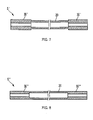
- FIGS. 7 and 8 show structures of refrigerant pipes 5' and 5" according to another embodiment of the present invention.
- a refrigerant pipe 5' can have the thickness of a connection pipe section 30' increased relative to the thickness of the main pipe section 20 by allowing the connection pipe section 30' to have an inner diameter smaller than that of the main pipe section 20 as well as an outer diameter larger than that of the main pipe section 20.
- a refrigerant pipe 5" can have the thickness of a connection pipe section 30" increased relative to the thickness of the main pipe section 20 by allowing the connection pipe section 30" to have an inner diameter smaller than that of the main pipe section 20 while having and outer diameter identical to that of the main pipe section 20.
- Such refrigerant pipes 5' and 5" can be fabricated by modifying the shape of the space 40a, the pin member 41 and the fixing jig 42 in correspondence with the shape of the refrigerant pipes 5' and 5". Accordingly, the pressing device 40 may have various shapes in correspondence with the shape of the refrigerant pipes 5' and 5" so that pressing device 40 can form the connection pipe sections 30' and 30" by deforming the end of the primary pipe 6.
- connection pipe section 30 By increasing the thickness of the connection pipe section 30, the strength of the connection pipe section 30 is reinforced so that the coupling strength between the refrigerant pipe and the components of the refrigeration cycle can be improved.
- the thickness of the main pipe section 20 is not increased and since the main pipe section 20 has a length longer than that of the connection pipe sections 30, it is not necessary to significantly increase the amount of materials used for manufacturing the refrigerant pipe.
- the refrigerant pipe 5, including the connection pipe sections 30 having relatively large thickness can be obtained by pressing both ends of the primary pipe 6 after the drawing process for the primary pipe 6 has cooled.
Landscapes
- Engineering & Computer Science (AREA)
- Physics & Mathematics (AREA)
- Mechanical Engineering (AREA)
- Thermal Sciences (AREA)
- General Engineering & Computer Science (AREA)
- Air-Conditioning For Vehicles (AREA)
- Rigid Pipes And Flexible Pipes (AREA)
- Compressor (AREA)
Applications Claiming Priority (1)
| Application Number | Priority Date | Filing Date | Title |
|---|---|---|---|
| KR1020070019712A KR20080079471A (ko) | 2007-02-27 | 2007-02-27 | 냉동사이클용 냉매관 및 그 제조방법 |
Publications (1)
| Publication Number | Publication Date |
|---|---|
| EP1965155A2 true EP1965155A2 (de) | 2008-09-03 |
Family
ID=39591374
Family Applications (1)
| Application Number | Title | Priority Date | Filing Date |
|---|---|---|---|
| EP08003250A Withdrawn EP1965155A2 (de) | 2007-02-27 | 2008-02-22 | Kühlmittelrohr für einen Kältekreislauf und Verfahren zu seiner Herstellung |
Country Status (3)
| Country | Link |
|---|---|
| EP (1) | EP1965155A2 (de) |
| KR (1) | KR20080079471A (de) |
| CN (1) | CN101256044A (de) |
-
2007
- 2007-02-27 KR KR1020070019712A patent/KR20080079471A/ko not_active Withdrawn
-
2008
- 2008-02-22 EP EP08003250A patent/EP1965155A2/de not_active Withdrawn
- 2008-02-26 CN CNA2008100809006A patent/CN101256044A/zh active Pending
Also Published As
| Publication number | Publication date |
|---|---|
| CN101256044A (zh) | 2008-09-03 |
| KR20080079471A (ko) | 2008-09-01 |
Similar Documents
| Publication | Publication Date | Title |
|---|---|---|
| US20080202622A1 (en) | Refrigerant pipe for refrigeration cycle and manufacturing method of the same | |
| US7866378B2 (en) | Double-wall pipe, method of manufacturing the same and refrigerant cycle device provided with the same | |
| US7887099B2 (en) | Compound tube and method of producing the same | |
| US7886420B2 (en) | Method of manufacturing double pipe | |
| JP5045795B2 (ja) | エジェクタおよびエジェクタの製造方法 | |
| US7124602B2 (en) | Direct cooling type refrigerator and evaporating pipe fixing method in the refrigerator | |
| JP4350079B2 (ja) | 二重管、その製造方法、およびそれを備える冷凍サイクル装置 | |
| KR101130849B1 (ko) | 이종금속의 공정접합부 꺾임 방지 파이프 및 이의 제조방법 | |
| CN100460794C (zh) | 双壁管及其制造方法和设有双壁管的制冷剂循环装置 | |
| JP2001038436A (ja) | 中空体の製造方法 | |
| JP2014055748A (ja) | 内部熱交換器とその製造方法 | |
| EP1965155A2 (de) | Kühlmittelrohr für einen Kältekreislauf und Verfahren zu seiner Herstellung | |
| KR20140112751A (ko) | 차량용 공조장치의 머플러 제조방법 및 그 머플러 | |
| JP2007327706A (ja) | 溝付き管、二重管、およびその製造方法 | |
| KR20130045722A (ko) | 석션파이프 어셈블리 및 그 제조방법 | |
| KR101687587B1 (ko) | 냉동사이클용 열교환기와 그 제조장치 및 제조방법 | |
| KR20110045132A (ko) | 석션 파이프와 모세관 파이프의 접합 구조 | |
| KR101951327B1 (ko) | 냉장고 | |
| KR100542494B1 (ko) | 에어컨 리시버드라이어 탱크와 그 가공장치 및 가공방법 | |
| US20080016904A1 (en) | Refrigerating Unit Comprising An Ultrasound-Welded Suction Tube And A Throttling Tube | |
| KR101973033B1 (ko) | 배관 연결 장치 | |
| KR102948074B1 (ko) | 냉동사이클용 일체형 파이프, 그 제조 시스템 및 제조 방법 | |
| JP2002031438A (ja) | 空気調和装置及びその製作方法 | |
| KR20140118073A (ko) | 관 연결구조 | |
| KR102385752B1 (ko) | 냉매 사이클 장치용 열교환 조립체 및 그 제조방법 |
Legal Events
| Date | Code | Title | Description |
|---|---|---|---|
| PUAI | Public reference made under article 153(3) epc to a published international application that has entered the european phase |
Free format text: ORIGINAL CODE: 0009012 |
|
| AK | Designated contracting states |
Kind code of ref document: A2 Designated state(s): AT BE BG CH CY CZ DE DK EE ES FI FR GB GR HR HU IE IS IT LI LT LU LV MC MT NL NO PL PT RO SE SI SK TR |
|
| AX | Request for extension of the european patent |
Extension state: AL BA MK RS |
|
| STAA | Information on the status of an ep patent application or granted ep patent |
Free format text: STATUS: THE APPLICATION HAS BEEN WITHDRAWN |
|
| 18W | Application withdrawn |
Effective date: 20100204 |