EP1964802A2 - System und Verfahren zur Messung und Steuerung von Abstandslängen - Google Patents
System und Verfahren zur Messung und Steuerung von Abstandslängen Download PDFInfo
- Publication number
- EP1964802A2 EP1964802A2 EP08003598A EP08003598A EP1964802A2 EP 1964802 A2 EP1964802 A2 EP 1964802A2 EP 08003598 A EP08003598 A EP 08003598A EP 08003598 A EP08003598 A EP 08003598A EP 1964802 A2 EP1964802 A2 EP 1964802A2
- Authority
- EP
- European Patent Office
- Prior art keywords
- processor
- controller
- sensors
- gap
- Prior art date
- Legal status (The legal status is an assumption and is not a legal conclusion. Google has not performed a legal analysis and makes no representation as to the accuracy of the status listed.)
- Withdrawn
Links
- 238000000034 method Methods 0.000 title claims abstract description 26
- 238000005259 measurement Methods 0.000 title claims abstract description 24
- 230000006870 function Effects 0.000 claims abstract description 12
- 238000012545 processing Methods 0.000 claims description 38
- 230000009471 action Effects 0.000 claims description 9
- 230000003993 interaction Effects 0.000 claims description 8
- 230000001276 controlling effect Effects 0.000 description 11
- 230000015654 memory Effects 0.000 description 10
- 230000008901 benefit Effects 0.000 description 7
- 238000004891 communication Methods 0.000 description 6
- 238000003860 storage Methods 0.000 description 5
- 238000011144 upstream manufacturing Methods 0.000 description 4
- 230000005540 biological transmission Effects 0.000 description 3
- 230000003287 optical effect Effects 0.000 description 3
- 230000008569 process Effects 0.000 description 3
- 230000004044 response Effects 0.000 description 3
- 238000001514 detection method Methods 0.000 description 2
- 238000003384 imaging method Methods 0.000 description 2
- 230000007246 mechanism Effects 0.000 description 2
- 238000012986 modification Methods 0.000 description 2
- 230000004048 modification Effects 0.000 description 2
- 230000002085 persistent effect Effects 0.000 description 2
- RYGMFSIKBFXOCR-UHFFFAOYSA-N Copper Chemical compound [Cu] RYGMFSIKBFXOCR-UHFFFAOYSA-N 0.000 description 1
- 230000001133 acceleration Effects 0.000 description 1
- 230000004913 activation Effects 0.000 description 1
- 238000013459 approach Methods 0.000 description 1
- 230000006399 behavior Effects 0.000 description 1
- 230000008859 change Effects 0.000 description 1
- 230000003467 diminishing effect Effects 0.000 description 1
- 230000000694 effects Effects 0.000 description 1
- 239000000835 fiber Substances 0.000 description 1
- 239000004973 liquid crystal related substance Substances 0.000 description 1
- 238000004519 manufacturing process Methods 0.000 description 1
- 238000010297 mechanical methods and process Methods 0.000 description 1
- 230000005226 mechanical processes and functions Effects 0.000 description 1
- 238000012544 monitoring process Methods 0.000 description 1
- 238000012015 optical character recognition Methods 0.000 description 1
- 230000002093 peripheral effect Effects 0.000 description 1
- 230000035484 reaction time Effects 0.000 description 1
- 230000001105 regulatory effect Effects 0.000 description 1
- 230000003068 static effect Effects 0.000 description 1
- 238000012795 verification Methods 0.000 description 1
- 238000005303 weighing Methods 0.000 description 1
Images



Classifications
-
- B—PERFORMING OPERATIONS; TRANSPORTING
- B65—CONVEYING; PACKING; STORING; HANDLING THIN OR FILAMENTARY MATERIAL
- B65H—HANDLING THIN OR FILAMENTARY MATERIAL, e.g. SHEETS, WEBS, CABLES
- B65H29/00—Delivering or advancing articles from machines; Advancing articles to or into piles
- B65H29/58—Article switches or diverters
- B65H29/60—Article switches or diverters diverting the stream into alternative paths
-
- B—PERFORMING OPERATIONS; TRANSPORTING
- B65—CONVEYING; PACKING; STORING; HANDLING THIN OR FILAMENTARY MATERIAL
- B65H—HANDLING THIN OR FILAMENTARY MATERIAL, e.g. SHEETS, WEBS, CABLES
- B65H2301/00—Handling processes for sheets or webs
- B65H2301/30—Orientation, displacement, position of the handled material
- B65H2301/32—Orientation of handled material
- B65H2301/321—Standing on edge
-
- B—PERFORMING OPERATIONS; TRANSPORTING
- B65—CONVEYING; PACKING; STORING; HANDLING THIN OR FILAMENTARY MATERIAL
- B65H—HANDLING THIN OR FILAMENTARY MATERIAL, e.g. SHEETS, WEBS, CABLES
- B65H2511/00—Dimensions; Position; Numbers; Identification; Occurrences
- B65H2511/20—Location in space
- B65H2511/22—Distance
-
- B—PERFORMING OPERATIONS; TRANSPORTING
- B65—CONVEYING; PACKING; STORING; HANDLING THIN OR FILAMENTARY MATERIAL
- B65H—HANDLING THIN OR FILAMENTARY MATERIAL, e.g. SHEETS, WEBS, CABLES
- B65H2513/00—Dynamic entities; Timing aspects
- B65H2513/50—Timing
-
- B—PERFORMING OPERATIONS; TRANSPORTING
- B65—CONVEYING; PACKING; STORING; HANDLING THIN OR FILAMENTARY MATERIAL
- B65H—HANDLING THIN OR FILAMENTARY MATERIAL, e.g. SHEETS, WEBS, CABLES
- B65H2553/00—Sensing or detecting means
- B65H2553/40—Sensing or detecting means using optical, e.g. photographic, elements
- B65H2553/41—Photoelectric detectors
- B65H2553/412—Photoelectric detectors in barrier arrangements, i.e. emitter facing a receptor element
-
- B—PERFORMING OPERATIONS; TRANSPORTING
- B65—CONVEYING; PACKING; STORING; HANDLING THIN OR FILAMENTARY MATERIAL
- B65H—HANDLING THIN OR FILAMENTARY MATERIAL, e.g. SHEETS, WEBS, CABLES
- B65H2701/00—Handled material; Storage means
- B65H2701/10—Handled articles or webs
- B65H2701/19—Specific article or web
- B65H2701/1916—Envelopes and articles of mail
Definitions
- the present subject matter relates generally to a system and method for controlling functions in a mail sorting system. More specifically, the present subject matter relates to a system and method for controlling functions in a mail sorting system based on gap and / or mail piece length measurement and tracking.
- gap length is defined as the distance between two mail pieces, i.e., the distance between a first mail piece's trailing edge and a second mail piece's leading edge.
- the gap length must be large enough to accommodate the time required for electromechanical devices (e.g., diverters, scales, printers, etc.) operable along the processing system's mail piece transport path to perform their functions.
- a mail sorter system it is common to include a series of tightly positioned transport belts guided by one or more pulleys, actuators, rollers, tracks and the like to transport mail pieces from an initial feed position to an output position. Close contact between the belts and mail pieces enables the physical transport of the mail pieces. Between the input position and output position various other modules may also operate upon or interact with the mail pieces; for example, an imaging system for interpreting the markings resident upon the mail pieces or one or more scales for weighing each mail piece. A plurality of mail bins for accumulating the sorted mail pieces may be located beyond the output position.
- gap length is controlled by the operation of the mail sorting system feeder at the front end of the system.
- Feeders operate using a set pitch; pitch being the distance between the leading edge of a first piece of mail and the leading edge of a second piece of mail.
- the pitch setting is generally established and controlled through the use of a processor/controller, which may regulate the timed release of mail pieces to affect the pitch, as well as control and monitor the various electromechanical devices of the sorter system. Knowing the length of the longest piece of mail fed to the feeder and operating at a set pitch allows for a minimum gap length at the output of the feeder.
- a fixed gap feeder sets a fixed amount of time between detection of the trailing edge of the mail piece that just left the feeder and when the next piece is advanced out of the feeder.
- controlling gap length at the output of the feeder does not guarantee control of the gap length at all points along the mail sorting system.
- gap length variation is a common occurrence during mail processing system operation.
- the present subject matter relates generally to a system and method for controlling functions in a mail sorting system based on gap length and / or mail piece length measurement and tracking.
- the system and method includes a plurality of sensors located along one or more mail piece transport paths. The sensors are used to collect data regarding the gap length between each mail piece transported through the system and the mail piece length.
- the gap length data is processed and stored within a controller/processor that uses the gap lengths to control the operation of one or more devices within the mail sorting system.
- the gap lengths may be used to control the operation of a diverter, a printer, a labeler or any other electromechanical, hardware or software device.
- the gap lengths can be used to trigger and/or inhibit the operation of the one or more devices.
- Fig. 1 is a schematic illustrating a plan view of a sorter system utilizing gap measurement, tracking and control.
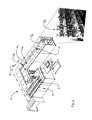
- Fig. 2 is an exemplary sorter system for processing mail pieces.
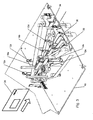
- Fig. 3 is a detailed illustration of a mail piece diverter system as employed along the mail transport path of the sorter system shown in Fig. 1 .
- Fig. 4 is a side view illustrating mail pieces being transported within the sorter system shown in Fig. 1 .
- Fig. 5 is an exemplary decision flow for using gap length to determine if a mail piece should be diverted.
- Fig. 6 is an exemplary decision flow for using gap length to determine if a mail piece should be printed.
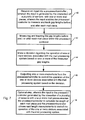
- Fig. 7 is a flow chart depicting a method of measuring gap lengths, tracking the gap lengths and controlling operations of a mail processing system based on one or more of the measurements.
- Fig. 1 illustrates a mail sorting system 10 wherein sensors 12 (including sensors 12a-12h) are located in proximity to conveyor belts 14 used to transport mail pieces 26 through the mail sorting system 10.
- sensors 12 including sensors 12a-12h
- the embodiment of the mail sorting system 10 shown in Fig. 1 includes a feeder 16, two diverters 18, two in-line scales 20 and a printer 22.
- the mail sorting system 10 further includes a processor/controller 24 associated with the other components of the system 10.
- any mail piece processing system e.g ., sorter, inserter, reject processor, etc.
- any electromechanical devices that may be employed in a mail processing system, particularly those having a set reaction time, may benefit by the application of the subject matter disclosed herein; for example, image lift systems, printers, labelers, diverters, etc. Therefore, the descriptions of the mail processing system, particularly the mail sorting system 10 herein, should not be limited to the configuration of devices illustrated in the example provided in Figs .1-4 .
- Fig. 4 illustrates a side view of mail pieces 26 being transported through the conveyor belts 14 in a portion of the mail sorting system 10 along a mail piece guidance track or platform 36.
- pitch P is defined as the distance between the leading edge 28a of a first mail piece 26 such as mail piece 26a and the leading edge of a second mail piece 26 such as mail piece 26b.
- the pre-gap G' is the distance between the trailing edge 30a of the first mail piece 26a and the leading edge 28b of the second mail piece 26b.
- the post-gap G is the distance between the trailing edge 30b of the second mail piece 26b and the leading edge 28c of the third mail piece 26c.
- the feeder 16 may include a mail piece input module and an imaging module (e.g., an integrated reader system and optical character recognition engine).
- the feeder 16 may be set to deliver the mail pieces 26 to the conveyor belts 14 at the input position I f based on a timing control, a pitch control or a gap control mechanism (e.g., as regulated by the processor/controller 24) in order to ensure there is an adequate pre-gap and post gap for each mail piece 26 to be properly handled, processed or otherwise acted on or measured by the various devices.
- a timing control e.g., as regulated by the processor/controller 24
- a sensor 12a immediately downstream of the feeder 16 at the feeder output position O f is a sensor 12a that measures the pre-gap, length and post gap of each mail piece 26 passed from the feeder 16 into the conveyor belts 14.
- This sensor 12a singularly or in combination with other upstream sensors, for example, sensor 11 verifies the feeder 16 is operating properly and also populates the processor/controller 24 with the initial measurements of pre-gap length, post-gap length and mail piece length for each mail piece 26.
- those skilled in the art may chose to measure and track various combinations of pre-gap, post-gap and length at any of the plurality of sensors along the transport path.
- the sensors 12 used in the example shown in Fig. 1 are infrared radiators and receivers. However it is contemplated that any photovoltaic sensors or other sensing mechanisms may be used in place of or in combination with the sensors 12 shown in Fig. 1 .
- one or more rotary encoders 35 may be utilized in connection with the sensors 12 in order to translate the sensor data into codes and/or instruction triggers to be interpreted by the processor/controller 24.
- the encoders 35 may be one or a combination of rotary encoders, linear encoders or any other like devices. The net result of encoder output is to provide a representation of conveyer belt speed.
- pre-gap G' is measured by calculating a value (e.g., distance) resulting from a period of time starting when the sensor 12 is unblocked ( e.g ., there is not a mail piece 26 adjacent to the sensor) to the moment the sensor 12 is blocked ( e.g ., there is a mail piece 26 adjacent to the sensor).
- a value e.g., distance
- length L is measured from the moment the sensor 12 is blocked to the moment the sensor 12 is unblocked.
- the post-gap G is measured from the moment the sensor 12 is unblocked to the moment the sensor 12 is blocked.
- the measurements may be calculated by the processor/controller 24 based on data supplied from the sensors 12 in lengths of hundredths of inches or in time values of milliseconds, to ensure precise measurements.
- the above described measurements are calculated and stored by the processor/controller 24 in data tables that include values for the current (i.e., growing) measurements as well as the final (i.e ., static) measurements, with separate tables wherein the values are stored/sorted by sensor 12 and by mail piece 26.
- each mail piece 26 can be assigned an identification based on the order it is passed through the mail sorting system 10 or, when an image lift system (not shown) is employed, by a mail piece identification generated or read by the image lift system.
- the measurement data may be supplied to the processor/controller 24 by any subset of the sensors 12 in the mail sorting system 10. For example, in the embodiment shown in Fig.
- all of the sensors 12 may be used for jam detection, but only sensors 12a-h are used for gap length measurements.
- the measurements may be made by any number of sensors 12 and calculated and stored by the processor/controller 24 in any manner apparent to one of ordinary skill in the art.
- Fig. 1 further illustrates virtual sensor positions 32 between the sensors 12.
- the virtual sensor positions 32 illustrate positions along the mail sorting system 10 wherein the processor/controller 24 updates its tables of stored values to predict the position of each mail piece 26. Therefore, at any given time in the operation of the mail sorting system 10, the processor/controller 24 will have data tables storing the values of the mail pieces 26 passing every sensor 12 and virtual sensor position 32.
- this persistent updating of measurement data throughout the operation of the mail sorting system 10 and particularly the fact that such data may be used to control further processing events, as will be described in further detail below, may improve the operating efficiency of the system by avoiding costly stoppages or other errors.
- the first diverter 18a diverts mail pieces 26 onto a first conveyor branch 34
- the second diverter 18b diverts mail pieces 26 to a second conveyor branch 36 and mail pieces 26 not diverted by either diverter 18 pass through along the main conveyor branch 38.
- the first conveyor branch 34 includes a first in-line scale 20a and the second conveyor branch 36 includes a second in-line scale 20b (the scales 20 are not shown in Fig. 3 ).
- the mail pieces 26 are returned to the main conveyor branch 38.
- the processor/controller 24 decides whether to actuate the first diverter 18a to divert the mail piece 26 onto the first conveyor branch 34. If the first diverter 18a is not instructed to actuate to divert a given mail piece 26, the processor/controller 24 decides whether to actuate the second diverter 18b as the mail piece 26 passes the second virtual sensor position 32 (i.e., the virtual sensor position 32 directly upstream of the first diverter 18a). If neither diverter 18 is able to divert a particular mail piece 26 (e.g.
- the mail piece 26 will pass the diverter 18 before the diverter 18 recovers from a previous diversion), or the processor/controller 24 had determined there is some error with the mail piece 26 (e.g ., the upstream sensors 12 have shown the mail piece 26 to have a changing length indicating a double piece error) the mail piece 26 passes straight through the main conveyor branch 38 without being diverted.
- the diverters 18 may be instructed not to activate when the pre-gap or post-gap is too small.
- sensors 12 are employed.
- sensors 12b and 12c may be employed to track the mail piece 26, verify its current path and determine if any jams have occurred as a result of improper diversion of a lagging mail piece 26 through diverter 18a.
- sensors 12d and 12e may be employed for tracking and path verification.
- additional sensors Prior to contact with a respective scale 20 and thereafter additional sensors may be employed.
- the data tables compiled in the processor/controller 24 may be updated at each sensor 12 and tracked at virtual sensor 32 or any subset of sensors 12 and virtual sensors 32.
- Controlling the action of the diverters 18 to prevent a diverter 18 from attempting to divert a mail piece 26 before the diverter 18 has been given a chance to recover from previous activity may prevent jams or other errors that would require a system stoppage. Preventing system stoppages is critical to maximizing system productivity.
- persistent updating of the current and final pre-gap G ', post-gap G, and length L information relative to each mail piece 26 arms the controller/processor 24 with feedback data, such that as an example, it may modify the behavior of a subsequent sensor or processing device in advance of the sensor's or device's actual processing of each mail piece 26.
- the processor/controller 24 may in some instances use data compiled from an upstream sensor 12 when controlling the actions of a particular device.
- the processor/controller 24 in the mail sorting system 10 shown in Fig. 1 may control the second diverter 18b based on data compiled from sensor 12a and the data received from sensor 12b is used simply to update the data tables.
- data received from sensor 12b may be used by the processor/controller 24 to control the operation of the second diverter 18b.
- the mail pieces 26 pass from the first conveyor branch 34 and the second conveyor branch 36 back to the mail conveyor branch 38 after they have been weighed by the in-line scales 20.
- the mail pieces 26 are transported past a printer 22.
- Printers 22 require a set time between mail pieces 26 in order to properly function. For example, certain printers 22 will dump the memory buffer containing the information required to print to a first mail piece 26 when the information required to print to a second mail piece 26 is received. Accordingly, if the information for the second mail piece 26 is received before the first mail piece 26 is completed being printed, a printing error may occur. Therefore, operation of the printer 22 may be controlled by the processor/controller 24 to minimize and track printing errors.
- the processor/controller 24 may choose not to print to a mail piece 26 if the trailing mail piece 26 is too close. Such a decision is made possible by the controller/processor 24 using the data compiled/updated at sensors 12g and/or 12f; measurements known prior to engagement of the mail piece 26 with sensor 12h, which is used in this example to trigger the printer 22.
- Fig. 1 relate to controlling the actions of diverters 18 and a printer 22, it is understood that the subject matter disclosed herein is equally applicable to any aspect of the mail sorting system 10 that has a set reaction/response time, whether hardware or software.
- One example is the in-line scales 20.
- the present subject matter may be used to control any action, inaction, mechanical process, electrical process, etc.
- An advantage of the mail sorting system 10 described herein is that the true throughput capability of the mail sorting system 10 can be determined by analyzing the theoretical gap length capability and the actual gap lengths measured. Accordingly, even if only four mail pieces 26 are passed through the mail sorting system 10 in a given hour, the measurements can be used to determine that the mail sorting system 10 is running at a pace capable of, for example, fifty thousand pieces per hour.
- system diagnostics can be based on whether the gap lengths are changing at a particular point along the mail sorting system 10. This can be used to determine component failure or other diagnostics. Indeed, relative conveyor belt acceleration rates may be adapted at points of diagnosed gap variation as a means of maintaining substantially optimal performance.
- Figs. 5 and 6 provide an exemplary decision flow for using gap length to determine if a mail piece should be diverted or printed under the control of the processor / controller 24. These examples are not intended to limit how those skilled in the art might implement alternative approaches. Both figures refer to Fig. 4 to show the relative positions of mail pieces and sensors.
- Fig. 5 (diverting) step 50 an envelope 26a is being conveyed by belts 14 through a diverter (not shown). The diverter was activated, when the envelope 26a first blocked sensor 12j, and will be in the process of closing to the no diversion position.
- envelope 26b is also set to be diverted when it reaches sensor 12j.
- gap G' is not yet measured by sensor 12j, the value is known since G' for envelope 26b was measured and tracked from sensor 12k along with other data associated with envelope 26b. If gap G' is too small to allow the diverter to complete it's open / close cycle without envelope 26b colliding with it 52, the diverter will be inhibited 54 instead of activated when envelope 26b arrives at sensor 12j. the envelope 26b will be rejected to the reject bin since the correct action was not performed on this mail piece. It is assumed of this example that the diverter must be inhibited before envelope 26b is detected by sensor 12j in order for the system to work correctly. If G' is large enough, envelope 26b will be diverted as required 56.
- envelope 26b is set to have information printed on the envelope starting shortly after it arrives at sensor 12j. If gap G, as measured when envelope 26b passed sensor 12k and envelope 26c arrived at sensor 12k, is not large enough to allow the printer to complete printing on envelope 26b before envelope 26c arrives at sensor 12j 62 then printing on envelope 26b will have to be inhibited 64. If envelope 26c arrives at sensor 12j before the printing on envelope 26b, the printer will halt printing which would cause a printing error for envelope 26b. The decision to not print on envelope 26b is only possible since the required gap length data had been measured and tracked at a sensor 12k that proceeds the control sensor 12j. If the gap G is large enough, envelope 26b will be printed.
- Fig. 7 illustrates an example of a method for controlling functions in a mail processing system using a processor/controller 24.
- the first step 40 shown in Fig. 7 is receiving an input in a processor/controller 24, wherein the input is generated by the interaction of a plurality of sensors 12 with one or more mail pieces 26, wherein the input enables the processor/controller 24 to measure and track gap lengths before and / or after each mail piece 26.
- the second step 42 shown in Fig 5 is measuring and tracking the gap lengths before and / or after each mail piece 26 within the processor/controller 24.
- the third step 44 shown in Fig. 7 is making a decision regarding the operation of one or more devices associated with the mail processing system based on one or more of the measured gap lengths.
- Fig. 7 is outputting one or more instructions from the processor/controller 24 to control the operation of the one or more devices associated with the mail processing system based on the decision.
- Fig. 7 also shows an optional fifth step 48 wherein the input to the processor/controller 24 generated by the interaction of a plurality of sensors 12 with one or more mail pieces 26 enables the processor/controller 24 to calculate the length of each mail piece 26 and the processor/controller 24 utilizes said length measurements to control the operation of the one or more devices associated with the mail processing system.
- the processor/controller 24 is controlled by the processor/controller 24.
- the processor/controller 24 is implemented by one or more programmable data processing devices.
- the hardware elements operating systems and programming languages of such devices are conventional in nature, and it is presumed that those skilled in the art are adequately familiar therewith.
- the processor/controller 24 may be a PC based implementation of a central control processing system.
- the exemplary system contains a central processing unit (CPU), memories and an interconnect bus.
- the CPU may contain a single microprocessor (e.g. a Pentium microprocessor), or it may contain a plurality of microprocessors for configuring the CPU as a multi-processor system.
- the memories include a main memory, such as a dynamic random access memory (DRAM) and cache, as well as a read only memory, such as a PROM, an EPROM, a FLASH-EPROM, or the like.
- the system also includes mass storage devices such as various disk drives, tape drives, etc. In operation, the main memory stores at least portions of instructions for execution by the CPU and data for processing in accord with the executed instructions.
- the mass storage may include one or more magnetic disk or tape drives or optical disk drives, for storing data and instructions for use by CPU.
- at least one mass storage system in the form of a disk drive or tape drive stores the operating system and various application software as well as data, such as received collating instructions and tracking or postage data generated in response to the collating operations.
- the mass storage within the computer system may also include one or more drives for various portable media, such as a floppy disk, a compact disc read only memory (CD-ROM), or an integrated circuit non-volatile memory adapter (i.e. PC-MCIA adapter) to input and output data and code to and from the computer system.
- PC-MCIA adapter integrated circuit non-volatile memory adapter
- the system also includes one or more input/output interfaces for communications, shown by way of example as an interface for data communications with one or more processing systems. Although not shown, one or more such interfaces may enable communications via a network, e.g., to enable sending and receiving instructions electronically.
- the physical communication links may be optical, wired, or wireless.
- the computer system may further include appropriate input/output ports for interconnection with a display and a keyboard serving as the respective user interface for the processor/controller 24.
- the computer may include a graphics subsystem to drive the output display.
- the output display for example, may include a cathode ray tube (CRT) display, or a liquid crystal display (LCD) or other type of display device.
- CTR cathode ray tube
- LCD liquid crystal display
- a PC type system implementation typically would include a port for connection to a printer.
- the input control devices for such an implementation of the system would include the keyboard for inputting alphanumeric and other key information.
- the input control devices for the system may further include a cursor control device (not shown), such as a mouse, a touchpad, a trackball, stylus, or cursor direction keys.
- the links of the peripherals to the system may be wired connections or use wireless communications.
- the computer system runs a variety of applications programs and stores data, enabling one or more interactions via the user interface provided, and/or over a network (to implement the desired processing.
- the components contained in the computer system are those typically found in general purpose computer systems. Although illustrated as a PC type device, those skilled in the art will recognize that the class of applicable computer systems also encompasses systems used as servers, workstations, network terminals, and the like. In fact, these components are intended to represent a broad category of such computer components that are well known in the art.
- a software or program product may take the form of code or executable instructions for causing a computer or other programmable equipment to perform the relevant data processing steps, where the code or instructions are carried by or otherwise embodied in a medium readable by a computer or other machine. Instructions or code for implementing such operations may be in the form of computer instruction in any form (e.g., source code, object code, interpreted code, etc.) stored in or carried by any readable medium.
- Non-volatile media include, for example, optical or magnetic disks, such as any of the storage devices in the computer system.
- Volatile media include dynamic memory, such as main memory.
- Transmission media include coaxial cables; copper wire and fiber optics including the wires that comprise a bus within a computer system. Transmission media can also take the form of electric or electromagnetic signals, or acoustic or light waves such as those generated during radio frequency or infrared data communications.
- various forms of computer readable media may be involved in carrying one or more sequences of one or more instructions to a processor for execution, for example, to install appropriate software in a system intended to serve as the processor/controller 24.
Landscapes
- Engineering & Computer Science (AREA)
- Mechanical Engineering (AREA)
- Sorting Of Articles (AREA)
- Length Measuring Devices By Optical Means (AREA)
Applications Claiming Priority (1)
| Application Number | Priority Date | Filing Date | Title |
|---|---|---|---|
| US11/710,911 US7631869B2 (en) | 2007-02-27 | 2007-02-27 | System and method for gap length measurement and control |
Publications (2)
| Publication Number | Publication Date |
|---|---|
| EP1964802A2 true EP1964802A2 (de) | 2008-09-03 |
| EP1964802A3 EP1964802A3 (de) | 2011-10-26 |
Family
ID=39469320
Family Applications (1)
| Application Number | Title | Priority Date | Filing Date |
|---|---|---|---|
| EP08003598A Withdrawn EP1964802A3 (de) | 2007-02-27 | 2008-02-27 | System und Verfahren zur Messung und Steuerung von Abstandslängen |
Country Status (2)
| Country | Link |
|---|---|
| US (1) | US7631869B2 (de) |
| EP (1) | EP1964802A3 (de) |
Cited By (2)
| Publication number | Priority date | Publication date | Assignee | Title |
|---|---|---|---|---|
| CH700243A1 (de) * | 2009-01-12 | 2010-07-15 | Ferag Ag | Computergesteuertes fördersystem und förderverfahren. |
| EP2282185A1 (de) * | 2009-07-29 | 2011-02-09 | Siemens Aktiengesellschaft | Verfahren und Vorrichtung zum näherungsweisen Wiegen eines Gegenstands |
Families Citing this family (9)
| Publication number | Priority date | Publication date | Assignee | Title |
|---|---|---|---|---|
| DE102006029728A1 (de) * | 2006-06-28 | 2008-01-03 | Siemens Ag | Sendungssortieranlage |
| US20120024669A1 (en) | 2010-07-29 | 2012-02-02 | Danelski Darin L | Networked Motorized Drive Roller Conveyor |
| US9446908B2 (en) | 2012-02-05 | 2016-09-20 | Matthews Resources, Inc. | Conveying systems and methods of associating data with an item transported by a conveying system |
| US10229383B2 (en) | 2012-02-05 | 2019-03-12 | Matthews International Corporation | Perpetual batch order fulfillment |
| DE202012011877U1 (de) * | 2012-12-07 | 2013-01-04 | Francotyp-Postalia Gmbh | Zuführstation |
| JP6225704B2 (ja) * | 2013-12-27 | 2017-11-08 | ブラザー工業株式会社 | 記録装置 |
| JP6225703B2 (ja) | 2013-12-27 | 2017-11-08 | ブラザー工業株式会社 | 記録装置 |
| JP6255995B2 (ja) | 2013-12-27 | 2018-01-10 | ブラザー工業株式会社 | 記録装置 |
| DE202016106125U1 (de) * | 2016-11-01 | 2016-12-22 | Francotyp-Postalia Gmbh | Dynamische Waage für auf der Seite liegend transportierte flache Güter |
Citations (3)
| Publication number | Priority date | Publication date | Assignee | Title |
|---|---|---|---|---|
| US6241099B1 (en) | 1999-05-12 | 2001-06-05 | Northrop Grumman Corporation | Flats bundle collator |
| WO2001075554A2 (en) | 2000-04-04 | 2001-10-11 | Opex Corporation | System and method for automated document processing |
| US20030168798A1 (en) | 2002-03-11 | 2003-09-11 | Pitney Bowes Incorporated | Transport method and system for controlling timing of mail pieces being processed by a mailing system |
Family Cites Families (18)
| Publication number | Priority date | Publication date | Assignee | Title |
|---|---|---|---|---|
| US4331328A (en) | 1980-06-30 | 1982-05-25 | Burroughs Corporation | Controller for a servo driven document feeder |
| US6064023A (en) * | 1986-09-05 | 2000-05-16 | Opex Corporation | Automated mail extraction and remittance processing |
| US4933616A (en) * | 1987-08-19 | 1990-06-12 | Pitney Bowes Inc. | Drive control system for imprinting apparatus |
| US4935078A (en) * | 1988-12-28 | 1990-06-19 | Pitney Bowes Inc. | High throughput mailing maching timing |
| US5295677A (en) * | 1992-08-28 | 1994-03-22 | Videojet Systems International, Inc. | Speed control for document handling system |
| US5423527A (en) | 1993-11-05 | 1995-06-13 | Unisys Corporation | Document transport with gap adjust |
| US5575466A (en) | 1994-11-21 | 1996-11-19 | Unisys Corporation | Document transport with variable pinch-roll force for gap adjust |
| US6499020B1 (en) * | 1999-06-07 | 2002-12-24 | Pitney Bowes Inc. | Method and device for improving the efficiency of a postage meter |
| US6711461B2 (en) | 2001-03-20 | 2004-03-23 | Lockheed Martin Corporation | Object and method for accessing of articles for reliable knowledge of article positions |
| US6613998B2 (en) * | 2001-03-23 | 2003-09-02 | Opex Corporation | Method and apparatus for processing outgoing bulk mail |
| US6644660B2 (en) * | 2001-10-26 | 2003-11-11 | Pitney Bowes Inc. | Dynamic pitch correction for an output inserter subsystem |
| US6554275B1 (en) * | 2001-12-04 | 2003-04-29 | Unisys Corporation | Method and system for document overlap/gap error detection and correction |
| US6688593B1 (en) * | 2002-07-31 | 2004-02-10 | Pitney Bowes Inc. | Envelope transport turn module and ramp for an output portion of an inserter system |
| US6783290B2 (en) * | 2002-08-05 | 2004-08-31 | Pitney Bowes Inc. | Method and system for high speed digital metering using low velocity print technology |
| US7099039B2 (en) * | 2002-08-22 | 2006-08-29 | Pitney Bowes Inc. | Parallel processing high speed printing system for an inserting system |
| US7040616B2 (en) * | 2002-12-17 | 2006-05-09 | Pitney Bowes Inc. | Method and system for high speed digital metering using overlapping envelopes |
| FR2865832A1 (fr) * | 2004-01-30 | 2005-08-05 | Neopost Ind | Dispositif de traitement de courrier au vol |
| US20090057997A1 (en) * | 2007-08-31 | 2009-03-05 | Seiko Epson Corporation | Printer, drive control method, and motor control program for printer |
-
2007
- 2007-02-27 US US11/710,911 patent/US7631869B2/en active Active
-
2008
- 2008-02-27 EP EP08003598A patent/EP1964802A3/de not_active Withdrawn
Patent Citations (3)
| Publication number | Priority date | Publication date | Assignee | Title |
|---|---|---|---|---|
| US6241099B1 (en) | 1999-05-12 | 2001-06-05 | Northrop Grumman Corporation | Flats bundle collator |
| WO2001075554A2 (en) | 2000-04-04 | 2001-10-11 | Opex Corporation | System and method for automated document processing |
| US20030168798A1 (en) | 2002-03-11 | 2003-09-11 | Pitney Bowes Incorporated | Transport method and system for controlling timing of mail pieces being processed by a mailing system |
Cited By (4)
| Publication number | Priority date | Publication date | Assignee | Title |
|---|---|---|---|---|
| CH700243A1 (de) * | 2009-01-12 | 2010-07-15 | Ferag Ag | Computergesteuertes fördersystem und förderverfahren. |
| WO2010078664A1 (de) * | 2009-01-12 | 2010-07-15 | Ferag Ag | Computergesteuertes fördersystem und förderverfahren |
| US8838267B2 (en) | 2009-01-12 | 2014-09-16 | Ferag Ag | Computer-controlled conveyor system and conveying method |
| EP2282185A1 (de) * | 2009-07-29 | 2011-02-09 | Siemens Aktiengesellschaft | Verfahren und Vorrichtung zum näherungsweisen Wiegen eines Gegenstands |
Also Published As
| Publication number | Publication date |
|---|---|
| US7631869B2 (en) | 2009-12-15 |
| EP1964802A3 (de) | 2011-10-26 |
| US20080208370A1 (en) | 2008-08-28 |
Similar Documents
| Publication | Publication Date | Title |
|---|---|---|
| US7631869B2 (en) | System and method for gap length measurement and control | |
| US4734865A (en) | Insertion machine with audit trail and command protocol | |
| US4959795A (en) | Insertion machine with distributed chargeback | |
| US9739656B2 (en) | Dynamic scale that uses multiple weight measurements of an object in continious motion to derrive a weight value and a quality value, where the quality value determines the validity of the weight value | |
| US6711461B2 (en) | Object and method for accessing of articles for reliable knowledge of article positions | |
| CA1057375A (en) | Malfunction detector system for item conveyor | |
| US8836964B2 (en) | Queued error reconciliation in a document processing environment | |
| US9827798B2 (en) | Assemblies, systems, and methods for applying postage indicia to one or more mailpiece on a high speed mail sorter | |
| JP5148265B2 (ja) | 区分装置及び区分装置の制御方法 | |
| EP2500305B1 (de) | Blattstapelvorrichtung | |
| NL8204048A (nl) | Installatie voor het toezicht houden op en het besturen van de fabricage, in het bijzonder van een drukpers. | |
| US6196537B1 (en) | Thickness measurement apparatus | |
| US20060201348A1 (en) | Dynamically changing label size during mail processing | |
| EP0390389B1 (de) | Verfahren und Vorrichtung zum Zuführen von Artikeln | |
| EP2876069B1 (de) | Kuvertiersystem und Verfahren zur Ausrichtung von Bögen | |
| US4031402A (en) | Stream feed detector for detecting document spacing | |
| KR101871439B1 (ko) | 매체 이송 처리 장치 및 방법과 그의 금융기기 | |
| EP0258495B1 (de) | Einfügungsmaschine mit Betriebszustandsnachspur und Steuerprotokoll | |
| JP3549339B2 (ja) | 紙葉類搬送装置の搬送エラー検出機構 | |
| US20080257796A1 (en) | Control Module Array for Sorters | |
| EP3241156A1 (de) | Anordnung und verfahren zum zählen von artikeln | |
| KR20070083633A (ko) | 지폐 식별 계수기 | |
| JPH11165933A (ja) | 紙葉類取り扱い装置 | |
| JP2007501176A (ja) | ソーティングマシンにおける平坦な送付物のオーバーラップの識別のための検出器の動作方法 | |
| JPH04112394A (ja) | 紙幣等の鑑別仕分け装置 |
Legal Events
| Date | Code | Title | Description |
|---|---|---|---|
| PUAI | Public reference made under article 153(3) epc to a published international application that has entered the european phase |
Free format text: ORIGINAL CODE: 0009012 |
|
| AK | Designated contracting states |
Kind code of ref document: A2 Designated state(s): AT BE BG CH CY CZ DE DK EE ES FI FR GB GR HR HU IE IS IT LI LT LU LV MC MT NL NO PL PT RO SE SI SK TR |
|
| AX | Request for extension of the european patent |
Extension state: AL BA MK RS |
|
| PUAL | Search report despatched |
Free format text: ORIGINAL CODE: 0009013 |
|
| AK | Designated contracting states |
Kind code of ref document: A3 Designated state(s): AT BE BG CH CY CZ DE DK EE ES FI FR GB GR HR HU IE IS IT LI LT LU LV MC MT NL NO PL PT RO SE SI SK TR |
|
| AX | Request for extension of the european patent |
Extension state: AL BA MK RS |
|
| RIC1 | Information provided on ipc code assigned before grant |
Ipc: B65H 29/60 20060101AFI20110920BHEP |
|
| RAP1 | Party data changed (applicant data changed or rights of an application transferred) |
Owner name: BELL AND HOWELL, LLC |
|
| 111Z | Information provided on other rights and legal means of execution |
Free format text: AT BE BG CH CY CZ DE DK EE ES FI FR GB GR HR HU IE IS IT LT LU LV MC MT NL NO PL PT RO SE SI SK TR Effective date: 20120201 |
|
| 17P | Request for examination filed |
Effective date: 20120329 |
|
| AKX | Designation fees paid |
Designated state(s): DE FR GB IT |
|
| STAA | Information on the status of an ep patent application or granted ep patent |
Free format text: STATUS: THE APPLICATION HAS BEEN WITHDRAWN |
|
| 18W | Application withdrawn |
Effective date: 20140405 |