EP1964677A2 - Device with several selectively operable function units - Google Patents
Device with several selectively operable function units Download PDFInfo
- Publication number
- EP1964677A2 EP1964677A2 EP08151859A EP08151859A EP1964677A2 EP 1964677 A2 EP1964677 A2 EP 1964677A2 EP 08151859 A EP08151859 A EP 08151859A EP 08151859 A EP08151859 A EP 08151859A EP 1964677 A2 EP1964677 A2 EP 1964677A2
- Authority
- EP
- European Patent Office
- Prior art keywords
- printing
- cylinder
- functional units
- valves
- register
- Prior art date
- Legal status (The legal status is an assumption and is not a legal conclusion. Google has not performed a legal analysis and makes no representation as to the accuracy of the status listed.)
- Withdrawn
Links
Images


Classifications
-
- B—PERFORMING OPERATIONS; TRANSPORTING
- B41—PRINTING; LINING MACHINES; TYPEWRITERS; STAMPS
- B41F—PRINTING MACHINES OR PRESSES
- B41F27/00—Devices for attaching printing elements or formes to supports
- B41F27/12—Devices for attaching printing elements or formes to supports for attaching flexible printing formes
- B41F27/1212—Devices for attaching printing elements or formes to supports for attaching flexible printing formes using pneumatic force
-
- B—PERFORMING OPERATIONS; TRANSPORTING
- B41—PRINTING; LINING MACHINES; TYPEWRITERS; STAMPS
- B41F—PRINTING MACHINES OR PRESSES
- B41F13/00—Common details of rotary presses or machines
-
- B—PERFORMING OPERATIONS; TRANSPORTING
- B41—PRINTING; LINING MACHINES; TYPEWRITERS; STAMPS
- B41F—PRINTING MACHINES OR PRESSES
- B41F27/00—Devices for attaching printing elements or formes to supports
- B41F27/005—Attaching and registering printing formes to supports
-
- B—PERFORMING OPERATIONS; TRANSPORTING
- B41—PRINTING; LINING MACHINES; TYPEWRITERS; STAMPS
- B41F—PRINTING MACHINES OR PRESSES
- B41F27/00—Devices for attaching printing elements or formes to supports
- B41F27/12—Devices for attaching printing elements or formes to supports for attaching flexible printing formes
- B41F27/1206—Feeding to or removing from the forme cylinder
-
- B—PERFORMING OPERATIONS; TRANSPORTING
- B41—PRINTING; LINING MACHINES; TYPEWRITERS; STAMPS
- B41P—INDEXING SCHEME RELATING TO PRINTING, LINING MACHINES, TYPEWRITERS, AND TO STAMPS
- B41P2227/00—Mounting or handling printing plates; Forming printing surfaces in situ
- B41P2227/10—Attaching several printing plates on one cylinder
- B41P2227/11—Attaching several printing plates on one cylinder in axial direction
-
- B—PERFORMING OPERATIONS; TRANSPORTING
- B41—PRINTING; LINING MACHINES; TYPEWRITERS; STAMPS
- B41P—INDEXING SCHEME RELATING TO PRINTING, LINING MACHINES, TYPEWRITERS, AND TO STAMPS
- B41P2227/00—Mounting or handling printing plates; Forming printing surfaces in situ
- B41P2227/50—Devices for storing printing plates
-
- B—PERFORMING OPERATIONS; TRANSPORTING
- B41—PRINTING; LINING MACHINES; TYPEWRITERS; STAMPS
- B41P—INDEXING SCHEME RELATING TO PRINTING, LINING MACHINES, TYPEWRITERS, AND TO STAMPS
- B41P2227/00—Mounting or handling printing plates; Forming printing surfaces in situ
- B41P2227/60—Devices for transferring printing plates
- B41P2227/62—Devices for introducing printing plates
-
- B—PERFORMING OPERATIONS; TRANSPORTING
- B41—PRINTING; LINING MACHINES; TYPEWRITERS; STAMPS
- B41P—INDEXING SCHEME RELATING TO PRINTING, LINING MACHINES, TYPEWRITERS, AND TO STAMPS
- B41P2227/00—Mounting or handling printing plates; Forming printing surfaces in situ
- B41P2227/60—Devices for transferring printing plates
- B41P2227/63—Devices for removing printing plates
Definitions
- the invention relates to a device having a plurality of selectively operable functional units according to the preamble of claim 1.
- a device is known with a plurality of selectively operable functional units, which device is arranged in or on a printing press outside a plate cylinder, wherein the functional units are each pneumatically actuated, the device having a valve control unit, the compressed air is supplied with three different pressures, the Valve control unit distributes the compressed air supplied to the device to the functional units, wherein the distribution of compressed air can be triggered by a machine control or on control switches.
- a cylinder of a printing press wherein the cylinder has at least two acted upon by a pressure medium actuating means and at least a first supply line for the supply of the pressure medium, wherein in the cylinder from the first supply line branching lines are provided for distributing the pressure medium to the actuating means and that in the lines to at least two actuating means each have a control valve is provided, wherein the control valve may be switchable with an electromagnetically designed actuating means.
- the invention has for its object to provide a device which is arranged outside of a plate cylinder in or on a printing press, with a plurality of pneumatically selectively operable functional units.
- the device is preferably arranged along a plate cylinder of the printing press.
- the solution shown is suitable for a device for automatic or semi-automatic assembly and / or disassembly of sections to be arranged on the plate cylinder pressure plates, for example in the case of the embodiment of the device as a register stop traverse and / or as a roller bar.
- Fig. 1 shows in highly simplified schematic form a printing machine 01, in particular a web-fed rotary printing machine 01 in the form of a printing tower 01, preferably a printing machine printing several different printing inks 01, with z. B. four in a frame 02 vertically stacked double printing units 03, wherein a substrate 05, z. B. a web of material 05, in particular a paper web 05, in the vertical direction, the double printing units 03 passes successively.
- the printing press 01 can be a printing press 01 that prints in the offset printing process, eg. B. be used in newspaper printing press 01.
- the printing machine 01 may, for. Example, use a conventional wet offset printing process, which uses a dampening solution for the printing process, or it can print in a so-called dry offset printing process in which the use of a dampening solution is not required.
- the two blanket cylinders 06 and the two plate cylinders 07 of two opposing printing units 04 of a double printing unit 03 are arranged so that their axes of rotation lie in a plane E which is inclined relative to the paper web 05 by preferably 75 ° to 88 °.
- Each printing unit 04 consisting of at least one blanket cylinder 06 and one plate cylinder 07 is assigned an inking unit 08, for example a roller inking unit 08 or a short inking unit 08. Furthermore, each printing unit 04 is assigned a dampening unit 09, for example a spray dampening unit 09. If working in a manner not shown in the "dry offset” or “waterless offset printing", no dampening solution and thus no dampening unit 09 is provided and the inking unit 08 may be formed, for example, as a pump inking unit.
- Each printing unit 04 of the printing machine 01 has at least one drive motor not shown here, which in its respective speed and preferably in an angular position of the cylinder 06 driven by it; 07 relative to at least one other cylinder 06; 07 of this printing press 01 is regulated on the basis of data provided in a data flow of an electronic machine master axis.
- the plate cylinder 07 and the blanket cylinder 06 may be drivingly connected to each other, in particular by means of gears.
- each blanket cylinder 06 and each plate cylinder 07 may be provided with its own, not shown here drive motor, in such a drive concept, a plate change on a plate cylinder 07 can be performed independently of a plate change on another plate cylinder 07th
- the printing units 04 or their plate cylinder 07 may be formed to receive a plurality of printing plates in the axial direction, in particular of 2, 3, 4, 5, 6, 7 or 8 printing plates in the axial direction, and possibly also for receiving a plurality of printing plates in the circumferential direction , in particular of two pressure plates in the circumferential direction.
- Fig. 1 are arranged on both sides of the paper web 05 in each case a double printing unit 03 arranged rubber cylinder 06 in a so-called rubber-rubber arrangement against each other, so that the mutually employed rubber cylinder 06 mutually act as a counter-pressure cylinder.
- printing units 04 can be combined to form a satellite printing unit, wherein, for example, four printing units 04 in each case are connected to one another by the remaining cylinders 06; 07 separate impression cylinder are arranged, wherein the paper web 05 is guided in each case between at least one employed on the impression cylinder transfer cylinder 06 and the impression cylinder.
- the printing tower 01 comprises two separable and mutually distance-variable frame modules 11; 12, which are displaceable along the lower and upper cross members 13, so that corresponding printing unit components are optimally accessible for setup, maintenance and possibly repair purposes.
- one of the rack modules 11; 12 stationary and the other frame module 12 or 11 be slidable.
- On each of the rack modules 11; 12 is in each case a printing unit 04 of a double printing unit 03 together with associated components such as in particular inking unit 08 and possibly dampening unit 09 are arranged.
- the printing cylinder 06; 07 i. the transfer cylinder 06 or blanket cylinder 06 and the forme cylinder 07 or plate cylinder 07, are respectively mounted in a bearing unit 10 and a linear bearing 10, wherein preferably both ends of each printing cylinder 06; 07 are mounted in a linear bearing 10.
- a linear bearing 10 supports a printing cylinder 06; 07 for rotation while allowing translation, so a linear travel of the printing cylinder 06; 07, for example, to the plate cylinder 07 from the blanket cylinder 06 z. B. to turn off for the purpose of a plate change.
- the structure of such a linear bearing 10 is known per se and essentially comprises a linearly displaceable slide or bearing block in which the radial bearing receiving the cylinder shaft is formed.
- Fig. 2 shows in connection with one of the printing units 04 of the printing press 01 or one of the forme cylinder 07, a system consisting of a forme cylinder 07 of the printing machine 01 and at least one plate changing device 20, z.
- Fig. 2 becomes clear that in the axial direction of the forme cylinder 07 more, z.
- Four Printing forms are arranged side by side can be arranged.
- the respective printing forms are each with the z.
- table-shaped feeder 20 can be fed to the forme cylinder 07, wherein each of the forme cylinder 07 to be supplied printing form placed on the feeder 20 or at least applied to this.
- the feeding device 20 may be formed in a development as a so-called disk magazine 20 in which a plurality of printing plates can be stored. In a disk magazine 20 are several printing plates z. B. stored at least in the axial direction of the forme cylinder 07 side by side.
- Fig. 2 is in each case a section A for each of the axially adjacent to each other in the axial direction of the forme cylinder 07 printing plates in association with the forme cylinder 07; B; C; D, wherein an axial extent or width of each section A; B; C; D is preferably approximately the width of that in the respective section A; B; C; D to be supplied printing form corresponds.
- the sections A; B; C; D also extend over the preferably tangentially to the lateral surface of the forme cylinder 07 employed feeder 20.
- the juxtaposed sections A; B; C; D of the forme cylinder 07 and its associated at least one feeder 20 are preferably each formed with the same width.
- the form cylinder 07 may be associated with a roller bar 18 which extends axially parallel to the forme cylinder 07 and either separately or z. B. in assembly with the feeder 20 may be formed, wherein the roller bar 18 spaced from the lateral surface of the forme cylinder 07 preferably both ends in a frame 02 (not shown here) of the printing machine 01 and the respective frame module 11; 12 is held.
- the roller bar 18 has in the axial direction of the forme cylinder 07 preferably a plurality, in each case the respective sections A; B; C; D assigned functional units, as the functional elements 19, for example, rolling elements 19, preferably rollers 19 have, for. B. three rollers 19 per section A; B; C; D, wherein the a certain section A; B; C; D assigned roles 19 z. B. regardless of the rollers 19 in another section A; B; C; D or in all other sections A; B; C; D can be employed on the lateral surface of the forme cylinder 07. It can also be provided that all juxtaposed rollers 19 of the roller bar 18 are in each case employed jointly on the lateral surface of the forme cylinder 07.
- the rollers 19 of the roller bar 18 can several, in the case of the basis of Fig. 2 to 6 explained embodiment, four not shown in detail functional units to be assigned, which are selectively pneumatically actuated by means of suitable actuators, for example, each by means of a cylinder-piston device, an elastically deformable, inflatable actuator or the like. The principle of controlling these actuators will be explained in more detail below.
- a device 21, in particular register device 21 for aligning and / or guiding an elevator 14 to be fed to the plate cylinder 07, in particular a printing plate 14 or a printing plate 14 explain. It is understood that preferably each of the plate cylinders 07 of the printing press 01 can be associated with a corresponding register device 21.
- printing forms 14 in the printing process of successive printing units 04 of a printing press 01 are arranged in register on their respective forme cylinder 07 in order to print from one another, printed by different printing units 04, but to the same print image belonging color separations of the printed product on the substrate 05 accurately print each other to print.
- a register in particular page register containing alignment and feeding of printing plates 14 to allow their respective forme cylinder 07, the participating in the printing process, z.
- printing forms 14 to be used in an offset printing method are trimmed along at least one edge, preferably along two of their edges, parallel to the two parallel lines of the type area mirror so that at least this one edge is always aligned parallel to the type area.
- the form cylinder 07 for the register setting of the printing plate 14 corresponding adjustment devices, eg. B. register pins o. ⁇ ., No longer needed.
- the means 14 laterally trimmed by means as described above is supplied with its at least one cropped edge of the forme cylinder 07 of the printing press 01, aligned during the feeding for a register-containing positioning laterally to this forme cylinder 07 and mounted there on the forme cylinder 07.
- the positionally accurate arrangement causes the lateral alignment of the printing plate 14 also that the trimmed edge of the printing plate 14 and thus the lines parallel to this edge lines of its type mirror are aligned orthogonal to the axis of the forme cylinder 07.
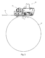
- the positionally accurate feeding in the axial direction of a printing forme 14 to the forme cylinder 07 takes place for. B. on a plate changing device 20 (see. Fig. 2 ) or from a plate magazine 20, preferably in such a way that a beveled end 16 of the printing plate 14 can be inserted in a longitudinal direction of the forme cylinder 07 extending below the lateral surface channel 17, wherein the channel 17 on the lateral surface of the forme cylinder 07 a z. B. slot-shaped opening, cf. Fig. 3 ,
- a holding device not shown here can be arranged in a conventional manner, the z. B. may be formed as a remotely controllable clamping device.
- FIG. 2 Another auxiliary device for mounting or removing the printing plate 14 may be associated with Fig. 2 be discussed roller bar 18, cf. also Fig. 3 ,
- the printing plate 14 with respect to the axial direction of the forme cylinder 07 in the correct position, d. H. in an orthogonal to the axial direction of the forme cylinder 07 alignment, is supplied and optionally fixed, outside of the forme cylinder 07 is a device 21 for laterally aligning and guiding the printing plate 14 produced in register, above and below also called functional unit 21, in particular register device 21, arranged.
- the register device 21 has z. B. a to the axis of the forme cylinder 07, that is, in the longitudinal direction, substantially parallel cross member 22 and a register cross member 22 and register carrier 22, the or the at least one, preferably a plurality of register stops 23; 24 carries. At least part of the functional elements 23; 24, for example register stops 23; 24 is movable on the register carrier 22 between a functional position in which it projects into the plane of the movement path of a printing form 14, and a rest position in which it does not protrude into the plane of the movement path of a printing plate 14.
- the register stops 23; 24 arranged at least substantially within the housing 22 defining a register carrier 22, while they are folded out in its operating position from the housing 22 and protrude into the plane of movement of the printing plates 14.
- Fig. 5 to 7 is in each case the functional position of the register stops 23; 24 shown.
- register stops 23; 24 these are in the case of in the Fig. 6 illustrated embodiment each held on a register carrier 22 via a respective pivot axis 25 pivotally mounted holder 26, which in turn cooperates with a disposed within the register carrier 22 cylinder piston means 27 which preferably operates pneumatically and remotely controllable, z. From the Control station of the printing press 01 can be controlled remotely.
- a carrier 30 of the housing 22 for receiving the pivot axes 25 of the holder 26 has exactly drilled pivot points and index holes.
- the position of the register stops 23; 24 are adjusted on the holder 26 in the longitudinal direction of the register carrier 22 by means of an adjusting device 28 within a defined setting range.
- register stops 23 and 24, the holder 26 together with the adjusting device 28 and the cylinder piston device 27 comprehensive device is hereinafter also functional unit 29, for example register stop means 29, called.
- the register stops 23; 24 are collapsed, for example, for an operating situation in which no printing form change should take place and pivoted when a printing plate 14 is supplied.
- one of the two register stops 23, each associated with a printing forme 14, is; 24, in the case of the embodiment of the respective register stop 24, resiliently formed. This can be done in any way, for example, either by using a resilient material for the register stop 24 or by a resilient mounting of the register stop 24.
- register stop devices 29 and functional units 29 can be composed.
- a four-page-wide register device 21 is shown, wherein in the illustration rightmost a rigid register stop 23 may be located, which can not be formed wegklappbar, and the leftmost register stop means 29 can only carry a resilient, swing-stop register stop 24 .
- By folding away certain register stop devices 29, different formats can be processed, for example, by folding away the first and third register stop devices 29, seen from the left, for printing panorama pages, printing plates 14 can be mounted in panorama format.
- the register devices 21 are a plurality of controllable valves 33; 34; 36; 37, which are preferably not permanently, but only temporarily connected via a single compressed air supply 39 or supply line 39, ie a line 39 with an external compressed air source 41, cf. Fig. 4 ,
- the valves 33; 34; 36; 37 are arranged in the form of a valve block 38 at one end of the register device 21 in the interior of the register cross 22 and the housing 22.
- the connection of the compressed air supply 39 to the register device 21 may, for. B. by means of a simply releasable coupling, z. B. a plug connection.
- valves 33; 34; 36; 37 controls 47; 48; 49; 51 is provided in the form of an actuating device 52, for example a control block 52, with which the valves 33; 34; 36; 37 selectively, ie, individually and independently of each other are preferably contactless actuated.
- the respective, in particular electrically and thus remotely triggerable controls 47; 48; 49; 51 are arranged fixed to the frame in the printing press 01, for example, but may also be arranged on or in the register crosspiece 22.
- the triggering of the respective controls 47; 48; 49; 51 can be done by a belonging to the printing machine 01 arithmetic unit.
- This arithmetic unit can z. B. be arranged in a belonging to the printing press 01 control station.
- the controls 47; 48; 49; 51 can for actuating the respective valves 33; 34; 36; 37 use a preferably magnetic or optionally inductive active principle.
- the respective valves 33; 34; 36; 37 are actuated by means of a radio signal.
- FIGS. 9 and 10 show three different embodiments of the respective pneumatic circuit of each of the valves 33; 34; 36; 37.
- the valves 33 remain; 34; 36; 37 after its operation in a self-holding, ie in a self-holding Operating condition.
- FIGS. 9 and 10 is in each case by a connected to the valve circuit working cylinder 53 from the valve 33; 34; 36 and 37 to be actuated cylinder-piston device 27 of the respective functional unit 29, z.
- the control of the rollers 19 of the roller bar 18 can take place in a manner corresponding to the preceding embodiments via a single supply line, provided on the roller bar 18 valves and corresponding possibly contactless controls, as has been described above in connection with the register device 21.
- At least one further device 21 with a plurality of pneumatically selectively operable functional units 29 may be arranged outside at least one of the plate cylinders 07 in or on the printing press 01 Function units 29 as well as the register device 21 at least one functional element 23; 24, wherein the device 21 also has a plurality of controllable valves 33; 34; 36; 37, wherein the valves 33; 34; 36; 37 are connected via a single compressed air supply 39 or line 39 with an external compressed air source 41.
- the valves 33; 34; 36; 37 are preferably in the form of a valve block 38 or a valve terminal 38 z.
- valves 33; 34; 36; 37 associated controls 47; 48; 49; 51 are provided, with which the valves 33; 34; 36; 37 selectively, ie individually and independently of each other preferably without a mechanical contact contact can be actuated.
- the controls 47; 48; 49; 51 can for actuating the respective valves 33; 34; 36; 37 use a preferably magnetic or optionally inductive active principle.
- the respective valves 33; 34; 36; 37 are actuated by means of a radio signal.
- One or more valve islands 38 may be provided in the device 21.
- the proposed devices 21 have in common that the respective device 21 is assigned only a single pneumatic supply line 39, said compressed air supply 39 is not permanently, but only as needed connected to the respective device 21, wherein the compressed air distribution to preferably substantially identical or at least similar Functional units 29 of this device 21 by means arranged in the respective device 21 valves 33; 34; 36; 37 takes place, these valves 33; 34; 36; 37 by means disposed outside the respective device 21 controls 47; 48; 49; 51 are contactlessly actuated.
- the proposed device 21 can also be a plate magazine 20, an automatic feeder for to be arranged on the forme 07 printing plates 14 or at least one printing plate 14 the forme cylinder 07 supplying feeder 20 each having a plurality of external Control unit be made of actuatable functional units 29.
- the respective functional units 29 z.
- each as a pneumatically actuated conveyor for conveying one or more printing plates 14 or as a pneumatically actuated aligning device with respect to a plate cylinder 07 entegot aligning at least one printing form 14 may be formed.
Abstract
Description
Die Erfindung betrifft eine Vorrichtung mit mehreren selektiv betätigbaren Funktionseinheiten gemäß dem Oberbegriff des Anspruch 1.The invention relates to a device having a plurality of selectively operable functional units according to the preamble of claim 1.
Durch die
Durch die
Durch die
Der Erfindung liegt die Aufgabe zugrunde, eine Vorrichtung, die außerhalb eines Plattenzylinders in oder an einer Druckmaschine angeordnet ist, mit mehreren, pneumatisch selektiv betätigbaren Funktionseinheiten zu schaffen. Die Vorrichtung ist vorzugsweise längs eines Plattenzylinders der Druckmaschine angeordnet.The invention has for its object to provide a device which is arranged outside of a plate cylinder in or on a printing press, with a plurality of pneumatically selectively operable functional units. The device is preferably arranged along a plate cylinder of the printing press.
Die Aufgabe wird erfindungsgemäß durch die Merkmale des Anspruchs 1 gelöst.The object is achieved by the features of claim 1.
Die mit der Erfindung erzielbaren Vorteile bestehen insbesondere darin, dass für die Versorgung von Funktionseinheiten dieser Vorrichtung mit Druckluft eine einzige Leitung ausreichend ist, was die Handhabung dieser Vorrichtung sowie deren Zugänglichkeit in oder an einer Druckmaschine erleichtert. Die Verteilung der Druckluft erfolgt erst in der Vorrichtung, und zwar mittels berührungslos steuerbarer Ventile und ihnen zugeordneter fernbetätigbarer Steuerelemente. Die Vorrichtung benötigt keine dauerhafte Verbindung mit einer Druckluftquelle.The achievable with the invention advantages are in particular that for the supply of functional units of this device with compressed air, a single line is sufficient, which facilitates the handling of this device and their accessibility in or on a printing press. The distribution of the compressed air takes place only in the device, by means of non-contact controllable valves and their associated remotely controllable controls. The device does not require a permanent connection to a compressed air source.
Die aufgezeigte Lösung ist für eine Vorrichtung zur automatischen oder halbautomatischen Montage und/oder Demontage von abschnittsweise auf den Plattenzylinder anzuordnenden Druckplatten geeignet, beispielsweise im Falle der Ausgestaltung der Vorrichtung als Registeranschlagstraverse und/oder als Rollenleiste.The solution shown is suitable for a device for automatic or semi-automatic assembly and / or disassembly of sections to be arranged on the plate cylinder pressure plates, for example in the case of the embodiment of the device as a register stop traverse and / or as a roller bar.
Ausführungsbeispiele der Erfindung sind in den Zeichnungen dargestellt und werden im Folgenden näher beschrieben.Embodiments of the invention are illustrated in the drawings and will be described in more detail below.
Es zeigen:
- Fig. 1
- eine Seitenansicht eines Druckturms;
- Fig. 2
- eine perspektivische Ansicht eines Druckwerkszylinders eines Druckwerks des Druckturms nach
Fig. 1 , samt zugehöriger Rollenleiste, jedoch ohne Registertraverse; - Fig. 3
- eine Seitenansicht eines Druckwerkszylinders eines Druckwerks des Druckturms nach
Fig. 1 , samt zugeordneter Registertraverse und Rollenleiste; - Fig. 4
- eine Teil-Draufsicht auf eine einem Druckwerkszylinder eines Druckwerks des Druckturms nach
Fig. 1 zugeordnete Registertraverse; - Fig. 5
- eine perspektivische Seitenansicht der Registertraverse nach
Fig. 4 ; - Fig. 6
- eine perspektivische Seitenansicht gemäß
Fig. 5 , jedoch mit geöffnetem Gehäuse; - Fig. 7
- einen Schnitt durch die Registertraverse nach
Fig. 5 senkrecht zu deren Längsrichtung; - Fig. 8
- eine Ausführung einer pneumatischen Schaltung eines einer Funktionseinheit zugeordneten Ventils;
- Fig. 9
- eine weitere Ausführungsform einer pneumatischen Schaltung eines einer Funktionseinheit zugeordneten Ventils;
- Fig. 10
- eine weitere Ausführungsform einer pneumatischen Schaltung eines einer Funktionseinheit zugeordneten Ventils.
- Fig. 1
- a side view of a printing tower;
- Fig. 2
- a perspective view of a printing cylinder of a printing unit of Printing tower after
Fig. 1 , including associated roller bar, but without register crossbar; - Fig. 3
- a side view of a printing cylinder of a printing unit of the printing tower after
Fig. 1 , including assigned register crossbar and roller bar; - Fig. 4
- a partial top view of a printing cylinder of a printing unit of the printing tower after
Fig. 1 associated register crossbar; - Fig. 5
- a perspective side view of the register traverse after
Fig. 4 ; - Fig. 6
- a perspective side view according to
Fig. 5 but with the housing open; - Fig. 7
- a section through the register traverse after
Fig. 5 perpendicular to the longitudinal direction thereof; - Fig. 8
- an embodiment of a pneumatic circuit of a functional unit associated valve;
- Fig. 9
- a further embodiment of a pneumatic circuit of a functional unit associated valve;
- Fig. 10
- a further embodiment of a pneumatic circuit of a functional unit associated valve.
In dem gezeigten Beispiel ist in jedem Doppeldruckwerk 03 beidseitig der Papierbahn 05 für den Schön- und Widerdruck jeweils ein Druckwerk 04 mit einem ersten Zylinder 06 bzw. Druckwerkszylinder 06, insbesondere einem Druckfarbe übertragenden, mit mindestens einem Gummituch bestückten Übertragungszylinder 06 bzw. Gummizylinder 06 und einem zweiten Zylinder 07, insbesondere Druckwerkszylinder 07, insbesondere einem auf dem Gummizylinder 06 abrollenden, eine oder mehrere Druckformen bzw. Druckplatten tragenden Formzylinder 07 bzw. Plattenzylinder 07 angeordnet. Die beiden Gummizylinder 06 und die beiden Plattenzylinder 07 zweier gegenüberliegender Druckwerke 04 eines Doppeldruckwerks 03 sind so angeordnet, dass ihre Rotationsachsen in einer Ebene E liegen, die gegenüber der Papierbahn 05 um vorzugsweise 75 ° bis 88 ° geneigt ist.In the example shown, in each
Jedem zumindest aus einem Gummizylinder 06 und einem Plattenzylinder 07 bestehenden Druckwerk 04 ist ein Farbwerk 08 zugeordnet, beispielsweise ein Walzenfarbwerk 08 oder ein Kurzfarbwerk 08. Weiterhin ist jedem Druckwerk 04 ein Feuchtwerk 09, beispielsweise ein Sprühfeuchtwerk 09 zugeordnet. Falls in nicht näher dargestellter Weise im "Trockenoffset" bzw. "wasserlosen Offsetdruck" gearbeitet wird, ist kein Feuchtmittel und somit auch kein Feuchtwerk 09 vorgesehen und das Farbwerk 08 kann beispielsweise als Pumpenfarbwerk ausgebildet sein.Each
Jedes Druckwerk 04 der Druckmaschine 01 weist mindestens einen hier nicht näher dargestellten Antriebsmotor auf, welcher in seiner jeweiligen Drehzahl und vorzugsweise auch in einer Winkellage des von ihm angetriebenen Zylinders 06; 07 relativ zu mindestens einem anderen Zylinder 06; 07 dieser Druckmaschine 01 aufgrund von in einem Datenfluss einer elektronischen Maschinenleitachse bereitgestellten Daten geregelt ist. Der Plattenzylinder 07 und der Gummizylinder 06 können antriebsmäßig miteinander verbunden sein, insbesondere mittels Zahnrädern. In alternativer Weise kann jeder Gummizylinder 06 und jeder Plattenzylinder 07 mit einem eigenen, hier nicht näher dargestellten Antriebsmotor versehen sein, wobei bei einem solchen Antriebskonzept ein Plattenwechsel an einem Plattenzylinder 07 unabhängig durchgeführt werden kann von einem Plattenwechsel an einem anderen Plattenzylinder 07.Each
Die Druckwerke 04 bzw. deren Plattenzylinder 07 können zur Aufnahme mehrerer Druckplatten in axialer Richtung ausgebildet sein, insbesondere von 2, 3, 4, 5, 6, 7 oder 8 Druckplatten in axialer Richtung, sowie ggf. auch zur Aufnahme von mehreren Druckplatten in Umfangsrichtung, insbesondere von zwei Druckplatten in Umfangsrichtung.The
In der Darstellung gemäß
Wie in
Die Druckwerkszylinder 06; 07, d.h. der Übertragungszylinder 06 bzw. Gummizylinder 06 und der Formzylinder 07 bzw. Plattenzylinder 07, sind jeweils in einer Lagereinheit 10 bzw. einem Linearlager 10 gelagert, wobei vorzugsweise jeweils beide Enden eines jeden Druckwerkszylinders 06; 07 in einem Linearlager 10 gelagert sind. Ein solches Linearlager 10 lagert einen Druckwerkszylinder 06; 07 zur Rotation und gestattet gleichzeitig eine Translation, also einen linearen Stellweg des Druckwerkszylinders 06; 07, beispielsweise, um den Plattenzylinder 07 vom Gummizylinder 06 z. B. zum Zwecke eines Plattenwechsels abzustellen. Der Aufbau eines solchen Linearlagers 10 ist an sich bekannt und umfasst im Wesentlichen einen linear verschieblichen Schlitten bzw. Lagerblock, in dem das die Zylinderwelle aufnehmende Radiallager ausgebildet ist.The
Aus
In der
Dem Formzylinder 07 kann eine Rollenleiste 18 zugeordnet sein, welche sich achsparallel zum Formzylinder 07 erstreckt und entweder separat oder z. B. in Baueinheit mit der Zuführeinrichtung 20 ausgebildet sein kann, wobei die Rollenleiste 18 beabstandet von der Mantelfläche des Formzylinders 07 vorzugsweise beidendig in einem Gestell 02 (hier nicht dargestellt) der Druckmaschine 01 bzw. des jeweiligen Gestellmoduls 11; 12 gehalten ist.The
Die Rollenleiste 18 weist in Axialrichtung des Formzylinders 07 vorzugsweise mehrere, jeweils den jeweiligen Abschnitten A; B; C; D zugeordnete Funktionseinheiten auf, die als Funktionselemente 19, beispielsweise Wälzelemente 19, vorzugsweise Rollen 19 aufweisen, z. B. drei Rollen 19 je Abschnitt A; B; C; D, wobei die einem bestimmten Abschnitt A; B; C; D zugeordneten Rollen 19 z. B. unabhängig von den Rollen 19 in einem anderen Abschnitt A; B; C; D oder in allen anderen Abschnitten A; B; C; D an die Mantelfläche des Formzylinders 07 angestellt werden können. Es kann auch vorgesehen sein, dass alle nebeneinander angeordneten Rollen 19 der Rollenleiste 18 jeweils gemeinsam an die Mantelfläche des Formzylinders 07 angestellt werden.The
Die Rollen 19 der Rollenleiste 18 können mehreren, im Falle des anhand der
Es wird nun auf die
Insbesondere im Mehrfarbendruck ist es für die Qualität eines herzustellenden Druckerzeugnisses wichtig, dass am Druck desselben Druckbildes beteiligte Druckformen 14 in im Druckprozess einander nachfolgenden Druckwerken 04 einer Druckmaschine 01 registerhaltig an ihrem jeweiligen Formzylinder 07 angeordnet sind, um voneinander verschiedene, von unterschiedlichen Druckwerken 04 gedruckte, aber zu demselben Druckbild gehörende Farbauszüge des Druckerzeugnisses auf dem Bedruckstoff 05 passgenau aufeinander zu drucken. Um eine registerhaltige, insbesondere seitenregisterhaltige Ausrichtung und Zuführung von Druckformen 14 zu ihrem jeweiligen Formzylinder 07 zu ermöglichen, werden die am Druckprozess beteiligten, z. B. in einem Offsetdruckverfahren einzusetzende Druckformen 14 nach ihrer Bebilderung entlang zumindest einer Kante, vorzugsweise entlang von zwei ihrer Kanten parallel zu den beiden parallelen Linien des Satzspiegels beschnitten, so dass mindestens diese eine Kante stets parallel zum Satzspiegel ausgerichtet ist. Wenn sichergestellt ist, dass die Druckform 14 exakt parallel zur Transportrichtung des das Druckbild aufnehmenden Bedruckstoffes 05 einem Formzylinder 07 der Druckmaschine 01 zugeführt und auf dem Formzylinder 07 montiert wird, werden am Formzylinder 07 für die Registereinstellung der Druckform 14 entsprechende Einstellvorrichtungen, z. B. Registerstifte o. ä., nicht mehr benötigt.Particularly in multicolor printing, it is important for the quality of a printed product to be produced that printing forms 14 in the printing process of
Die mittels wie vorstehend beschrieben seitlich beschnittene Druckform 14 wird mit ihrer zumindest einen beschnittenen Kante dem Formzylinder 07 der Druckmaschine 01 zugeführt, während des Zuführens für eine registerhaltige Positionierung seitlich zu diesem Formzylinder 07 ausgerichtet und dort auf dem Formzylinder 07 montiert. Außer der positionsgenauen Anordnung bewirkt die seitliche Ausrichtung der Druckform 14 auch, dass die beschnittene Kante der Druckform 14 und damit auch die zu dieser Kante parallelen Linien ihres Satzspiegels orthogonal zur Achse des Formzylinders 07 ausgerichtet werden.The means 14 laterally trimmed by means as described above is supplied with its at least one cropped edge of the
Die in axialer Richtung positionsgenaue Zuführung einer Druckform 14 zum Formzylinder 07 erfolgt z. B. über einer Plattenwechselvorrichtung 20 (vgl.
Eine weitere Hilfsvorrichtung für das Aufziehen oder Abnehmen der Druckform 14 kann die im Zusammenhang mit
Damit die Druckform 14 hinsichtlich der axialen Richtung des Formzylinders 07 in der richtigen Lage, d. h. in einer zur axialen Richtung des Formzylinders 07 orthogonalen Ausrichtung, zugeführt und gegebenenfalls fixiert wird, ist außerhalb des Formzylinders 07 eine Vorrichtung 21 zum seitlichen Ausrichten und Führen der registerhaltig hergestellten Druckform 14, weiter oben und im Folgenden auch Funktionseinheit 21, insbesondere Registervorrichtung 21 genannt, angeordnet.Thus, the
Die Registervorrichtung 21 weist z. B. einen zur Achse des Formzylinders 07, d. h. in dessen Längsrichtung, im Wesentlichen parallel verlaufenden Traverse 22 bzw. eine Registertraverse 22 bzw. Registerträger 22 auf, der bzw. die mindestens einen, vorzugsweise mehrere Registeranschläge 23; 24 trägt. Zumindest ein Teil der Funktionselemente 23; 24, beispielsweise Registeranschläge 23; 24 ist am Registerträger 22 zwischen einer Funktionsposition, in der er in die Ebene des Bewegungsweges einer Druckform 14 ragt, und einer Ruheposition, in der er nicht in die Ebene des Bewegungsweges einer Druckform 14 ragt, bewegbar. In der Ruheposition sind die Registeranschläge 23; 24 zumindest im Wesentlichen innerhalb des ein Gehäuse 22 definierenden Registerträgers 22 angeordnet, während sie in ihrer Funktionsposition aus dem Gehäuse 22 herausgeklappt sind und in die Bewegungsebene der Druckformen 14 ragen. In den
Zum Bewegen der Registeranschläge 23; 24 sind diese im Falle des in der
Für eine Justierung der Registeranschläge 23; 24 in Abhängigkeit von bestimmten Betriebsbedingungen, beispielsweise Fan-Out-Effekten, kann die Position der Registeranschläge 23; 24 am Halter 26 in Längsrichtung des Registerträgers 22 mittels einer Justiereinrichtung 28 innerhalb eines definierten Stellbereichs eingestellt werden.For an adjustment of the register stops 23; 24, depending on certain operating conditions, such as fan-out effects, the position of the register stops 23; 24 are adjusted on the
Die die Registeranschläge 23 bzw. 24, den Halter 26 samt Justiereinrichtung 28 und die Zylinder-Kolben-Einrichtung 27 umfassende Einrichtung wird im Folgenden auch Funktionseinheit 29, beispielsweise Registeranschlageinrichtung 29, genannt.The register stops 23 and 24, the
Die Registeranschläge 23; 24 sind beispielsweise eingeklappt für eine Betriebssituation, in welcher kein Druckformwechsel stattfinden soll und angeschwenkt, wenn eine Druckform 14 zugeführt wird. Über die Länge des Formzylinders 07, welche im Wesentlichen der Breite von z. B. vier Druckseiten, z. B. Zeitungsseiten, entspricht, sind in einem solchen Fall vier Paare von Registeranschlägen 23; 24 (für jede der vier Druckformen 14 jeweils einer) vorgesehen, wobei jede Druckform 14 zwischen jeweils einem Registeranschlag 23 und einem Registeranschlag 24 ausgerichtet und geführt wird.The register stops 23; 24 are collapsed, for example, for an operating situation in which no printing form change should take place and pivoted when a
Um ein Verklemmen der zuzuführenden Druckform 14 während ihrer Zuführung zum Formzylinder 07 wirksam zu vermeiden, ist einer der beiden jeweils einer Druckform 14 zugeordneten Registeranschläge 23; 24, im Falle des Ausführungsbeispiels der jeweilige Registeranschlag 24, federnd ausgebildet. Dies kann in beliebiger Weise beispielsweise entweder durch Verwendung eines federnden Materials für den Registeranschlag 24 oder durch eine federnde Lagerung des Registeranschlags 24 bewerkstelligt werden. Somit wird mindestens eine dem Formzylinder 07 zuzuführende Druckform 14, vorzugsweise jedoch jede dem Formzylinder 07 zuzuführende Druckform 14 seitlich jeweils zwischen einem in axialer Richtung des Formzylinders 07 starren (aber ggf. justierbaren) Registeranschlag 23 und einem federnden (und ggf. ebenfalls justierbaren) Registeranschlag 24 geführt.In order to effectively avoid jamming of the supplied
Aus der Darstellung nach
Zum Steuern der Bewegung der Funktionselemente 23; 24, d.h. hier der Registeranschläge 23; 24 bzw. zum Steuern der Funktionseinheiten 21, d.h. hier der Registervorrichtungen 21 sind mehrere steuerbare Ventile 33; 34; 36; 37 vorgesehen, die über eine einzige Druckluftzufuhr 39 bzw. Versorgungsleitung 39, d. h. eine Leitung 39 mit einer äußeren Druckluftquelle 41 vorzugsweise nicht dauerhaft, sondern nur zeitweise verbunden sind, vgl.
Über Leitungen 42; 43; 44; 46 sind die Ventile 33; 34; 36; 37 in dem in den Figuren dargestellten Beispiel der Registervorrichtung 21 den entsprechenden Registeranschlagseinrichtungen 29, d.h. im Falle des Ausführungsbeispiels den jeweiligen Zylinder-Kolben-Einrichtungen 27, zugeordnet und die Ventile 33; 34; 36; 37 steuern die jeweils gewünschte bzw. erforderliche Druckluftverteilung zu den jeweiligen Registeranschlagseinrichtungen 29. Lediglich zum Zwecke der klareren Darstellung sind in
Wie in der
Die Auslösung der jeweiligen Steuerelemente 47; 48; 49; 51 kann von einer zur Druckmaschine 01 gehörenden Recheneinheit aus erfolgen. Diese Recheneinheit kann z. B. in einem zur Druckmaschine 01 gehörenden Leitstand angeordnet sein. Die Steuerelemente 47; 48; 49; 51 können zur Betätigung der jeweiligen Ventile 33; 34; 36; 37 ein vorzugsweise magnetisches oder ggf. auch induktives Wirkprinzip verwenden. Es kann jedoch auch vorgesehen sein, dass die jeweiligen Ventile 33; 34; 36; 37 mittels eines Funksignals betätigt werden.The triggering of the
Die
Die Steuerung der Rollen 19 der Rollenleiste 18 kann in einer den vorstehenden Ausführungen entsprechenden Weise über eine einzige Zuführleitung, an der Rollenleiste 18 vorgesehene Ventile und entsprechende ggf. kontaktlose Steuerelemente erfolgen, wie dies im Vorstehenden im Zusammenhang mit der Registervorrichtung 21 beschrieben worden ist.The control of the
Es versteht sich, dass die mehrere Funktionseinheiten 29 umfassende Vorrichtung 21, also die mehrere Registeranschlagseinrichtungen 29 umfassende Registervorrichtung 21 zusätzlich auch im Falle des Ausführungsbeispiels nach
Alternativ oder zusätzlich zu der erläuterten Registervorrichtung 21, welche ein bevorzugtes Ausführungsbeispiel der Erfindung ist, kann außerhalb zumindest von einem der Plattenzylinder 07 in oder an der Druckmaschine 01 mindestens eine weitere Vorrichtung 21 mit mehreren, pneumatisch selektiv betätigbaren Funktionseinheiten 29 angeordnet sein, wobei jede der Funktionseinheiten 29 ebenso wie die Registervorrichtung 21 mindestens ein Funktionselement 23; 24 aufweist, wobei die Vorrichtung 21 zudem mehrere steuerbare Ventile 33; 34; 36; 37 aufweist, wobei die Ventile 33; 34; 36; 37 über eine einzige Druckluftzufuhr 39 bzw. Leitung 39 mit einer äußeren Druckluftquelle 41 verbindbar sind. Die Ventile 33; 34; 36; 37 sind vorzugsweise in Form eines Ventilblocks 38 oder einer Ventilinsel 38 z. B. an einem Ende der Vorrichtung 21 an oder in deren Gehäuse 22 angeordnet, wobei außerhalb der Vorrichtung 21 den jeweiligen Ventilen 33; 34; 36; 37 zugeordnete Steuerelemente 47; 48; 49; 51 vorgesehen sind, mit welchen die Ventile 33; 34; 36; 37 selektiv, d. h. einzeln und unabhängig voneinander vorzugsweise ohne einen mechanischen Berührungskontakt betätigbar sind. Die Steuerelemente 47; 48; 49; 51 können zur Betätigung der jeweiligen Ventile 33; 34; 36; 37 ein vorzugsweise magnetisches oder ggf. auch induktives Wirkprinzip verwenden. Es kann jedoch auch vorgesehen sein, dass die jeweiligen Ventile 33; 34; 36; 37 mittels eines Funksignals betätigt werden. Es können in der Vorrichtung 21 eine oder mehrere Ventilinseln 38 vorgesehen sein.Alternatively or in addition to the described
Den vorgeschlagenen Vorrichtungen 21 ist gemeinsam, dass der jeweiligen Vorrichtung 21 nur eine einzige pneumatische Versorgungsleitung 39 zugeordnet ist, wobei diese Druckluftzufuhr 39 nicht permanent, sondern nur bedarfsweise mit der jeweiligen Vorrichtung 21 verbunden ist, wobei die Druckluftverteilung zu vorzugsweise im Wesentlichen baugleichen oder zumindest gleichartigen Funktionseinheiten 29 dieser Vorrichtung 21 mithilfe von in der jeweiligen Vorrichtung 21 angeordneten Ventilen 33; 34; 36; 37 erfolgt, wobei diese Ventile 33; 34; 36; 37 mittels außerhalb der jeweiligen Vorrichtung 21 angeordneter Steuerelemente 47; 48; 49; 51 berührungslos betätigbar sind.The proposed
Außer in Form der bereits beschriebenen Registervorrichtung 21 oder Rollenleiste 18 kann die vorgeschlagene Vorrichtung 21 auch als ein Plattenmagazin 20, ein Beschickungsautomat für auf dem Formzylinder 07 anzuordnende Druckformen 14 oder eine mindestens eine Druckform 14 dem Formzylinder 07 zuführende Zuführeinrichtung 20 jeweils mit mehreren von einer externen Steuereinheit aus betätigbaren Funktionseinheiten 29 ausgebildet sein. Bei einem Plattenmagazin 20 oder einem Beschickungsautomat oder einer Zuführeinrichtung 20 können die jeweiligen Funktionseinheiten 29 z. B. jeweils als eine pneumatisch betätigte Fördereinrichtung zum Befördern einer oder mehrerer Druckformen 14 oder als eine pneumatisch betätigte Ausrichteeinrichtung zum mit Bezug auf einen Plattenzylinder 07 seitenregisterhaltigen Ausrichten zumindest einer Druckform 14 ausgebildet sein.Except in the form of the already described
- 0101
- Druckmaschine, Rollenrotationsdruckmaschine, DruckturmPrinting machine, web-fed rotary printing machine, printing tower
- 0202
- Gestellframe
- 0303
- DoppeldruckwerkDouble printing
- 0404
- Druckwerkprinting unit
- 0505
- Bedruckstoff, Materialbahn, PapierbahnSubstrate, web, paper web
- 0606
- Zylinder, Druckwerkszylinder, Übertragungszylinder, GummizylinderCylinder, printing cylinder, transfer cylinder, rubber cylinder
- 0707
- Zylinder, Druckwerkszylinder, Formzylinder, PlattenzylinderCylinder, printing cylinder, forme cylinder, plate cylinder
- 0808
- Farbwerk, Walzenfarbwerk, KurzfarbwerkInking unit, roller inking unit, short inking unit
- 0909
- Feuchtwerk, SprühfeuchtwerkDampening unit, spray dampening unit
- 1010
- Lagereinheit, LinearlagerBearing unit, linear bearing
- 1111
- Gestellmodulrack module
- 1212
- Gestellmodulrack module
- 1313
- Querträgercrossbeam
- 1414
- Aufzug, Druckform, DruckplatteElevator, printing form, printing plate
- 1515
- --
- 1616
- Ende, abgekantet (14)End, folded (14)
- 1717
- Kanalchannel
- 1818
- Rollenleisteroller strip
- 1919
- Funktionselement, Wälzelement, RolleFunctional element, rolling element, roller
- 2020
- Plattenwechselvorrichtung, Zuführeinrichtung, PlattenmagazinPlate changing device, feeder, plate magazine
- 2121
- Vorrichtung zum seitlichen Führen und/oder Ausrichten, Funktionseinheit, RegistervorrichtungDevice for lateral guidance and / or alignment, functional unit, register device
- 2222
- Traverse, Registertraverse, Registerträger, GehäuseTraverse, register crossbar, register carrier, housing
- 2323
- Funktionselement, RegisteranschlagFunction element, register stop
- 2424
- Funktionselement, RegisteranschlagFunction element, register stop
- 2525
- Schwenkachseswivel axis
- 2626
- Halterholder
- 2727
- Zylinder-Kolben-EinrichtungCylinder-piston means
- 2828
- Justiereinrichtungadjusting
- 2929
- Funktionseinheit, RegisteranschlageinrichtungFunction unit, register stop device
- 3030
- Trägercarrier
- 3131
- --
- 3232
- --
- 3333
- VentilValve
- 3434
- VentilValve
- 3535
- --
- 3636
- VentilValve
- 3737
- VentilValve
- 3838
- Ventilblock, VentilinselValve block, valve terminal
- 3939
- Druckluftzufuhr, Versorgungsleitung, LeitungCompressed air supply, supply line, line
- 4040
- --
- 4141
- DruckluftquelleCompressed air source
- 4242
- Leitungmanagement
- 4343
- Leitungmanagement
- 4444
- Leitungmanagement
- 4545
- --
- 4646
- Leitungmanagement
- 4747
- Steuerelementcontrol
- 4848
- Steuerelementcontrol
- 4949
- Steuerelementcontrol
- 5050
- --
- 5151
- Steuerelementcontrol
- 5252
- Betätigungseinrichtung, SteuerblockActuating device, control block
- 5353
- Arbeitszylinderworking cylinder
- AA
- Abschnittsection
- BB
- Abschnittsection
- CC
- Abschnittsection
- DD
- Abschnittsection
- Ee
- Ebenelevel
Claims (34)
Applications Claiming Priority (2)
| Application Number | Priority Date | Filing Date | Title |
|---|---|---|---|
| DE102007010298 | 2007-03-02 | ||
| DE102007000639A DE102007000639B3 (en) | 2007-03-02 | 2007-11-07 | Form cylinder e.g. double-size form cylinder, for use in printing mechanism of rotary printing machine, has printing plate arranged in sections, and control device actuating control valves in non-contact manner |
Publications (2)
| Publication Number | Publication Date |
|---|---|
| EP1964677A2 true EP1964677A2 (en) | 2008-09-03 |
| EP1964677A3 EP1964677A3 (en) | 2012-04-04 |
Family
ID=39587568
Family Applications (1)
| Application Number | Title | Priority Date | Filing Date |
|---|---|---|---|
| EP08151859A Withdrawn EP1964677A3 (en) | 2007-03-02 | 2008-02-25 | Device with several selectively operable function units |
Country Status (2)
| Country | Link |
|---|---|
| EP (1) | EP1964677A3 (en) |
| DE (1) | DE102007000639B3 (en) |
Citations (3)
| Publication number | Priority date | Publication date | Assignee | Title |
|---|---|---|---|---|
| DE10238177B3 (en) | 2002-08-21 | 2004-02-05 | Koenig & Bauer Ag | Web-fed printing machine has printer unit printing width of six axially adjacent pages, with superstructure, at least one roller and folder and two printing towers |
| DE10244574A1 (en) | 2002-09-25 | 2004-04-15 | Koenig & Bauer Ag | Cylinder of a printing press |
| DE102005017182A1 (en) | 2005-04-13 | 2006-10-19 | Man Roland Druckmaschinen Ag | Apparatus and method for pressing a fabric to a printing cylinder of a rotary printing machine |
Family Cites Families (2)
| Publication number | Priority date | Publication date | Assignee | Title |
|---|---|---|---|---|
| DE102004023434A1 (en) * | 2004-05-10 | 2005-12-08 | Maschinenfabrik Wifag | Rotary printing machine with suction device, suction device and method for changing a printing form |
| ATE527114T1 (en) * | 2004-05-14 | 2011-10-15 | Koenig & Bauer Ag | METHOD FOR PRODUCING A PRINTING FORM |
-
2007
- 2007-11-07 DE DE102007000639A patent/DE102007000639B3/en not_active Expired - Fee Related
-
2008
- 2008-02-25 EP EP08151859A patent/EP1964677A3/en not_active Withdrawn
Patent Citations (3)
| Publication number | Priority date | Publication date | Assignee | Title |
|---|---|---|---|---|
| DE10238177B3 (en) | 2002-08-21 | 2004-02-05 | Koenig & Bauer Ag | Web-fed printing machine has printer unit printing width of six axially adjacent pages, with superstructure, at least one roller and folder and two printing towers |
| DE10244574A1 (en) | 2002-09-25 | 2004-04-15 | Koenig & Bauer Ag | Cylinder of a printing press |
| DE102005017182A1 (en) | 2005-04-13 | 2006-10-19 | Man Roland Druckmaschinen Ag | Apparatus and method for pressing a fabric to a printing cylinder of a rotary printing machine |
Also Published As
| Publication number | Publication date |
|---|---|
| EP1964677A3 (en) | 2012-04-04 |
| DE102007000639B3 (en) | 2008-08-07 |
Similar Documents
| Publication | Publication Date | Title |
|---|---|---|
| DE102013217948B4 (en) | Printing machine for securities printing with an Orlof offset printing unit | |
| EP2736723B1 (en) | Plate cylinder | |
| DE19745136B4 (en) | Rotary sheet printing press | |
| EP1708886B2 (en) | Printing machine with a device and a method for compensation of a longitudinal elongation and a transverse elongation of a printed web printed in differing printig couples | |
| DE102009002103B4 (en) | Printing machine and a method for printing a web-shaped substrate | |
| WO2009033909A1 (en) | Printing group, printing press, and method for the operation of a printing group | |
| EP2029362B1 (en) | Method for operating a nine cylinders satellite printing unit | |
| DE19916257B4 (en) | Multi-color printing machine for the optional printing of single webs or two webs | |
| DE4218422A1 (en) | Sheet-fed offset rotary printing machine with removable imprinting or finishing unit | |
| WO2009130078A1 (en) | Newspaper printing press having an additional printing apparatus, and method for variable printing in newspaper production | |
| EP0995596B1 (en) | Device and method and for carrying out a flying printing plate exchange | |
| EP1226937B1 (en) | Shaftless motor drive for a printing machine with an anilox inking roller | |
| EP0924069A2 (en) | Sheet guiding device in a printing machine | |
| CH685380A5 (en) | Rotary printing machining with print works | |
| DE102007000639B3 (en) | Form cylinder e.g. double-size form cylinder, for use in printing mechanism of rotary printing machine, has printing plate arranged in sections, and control device actuating control valves in non-contact manner | |
| DE10232109A1 (en) | Offset printing unit and offset printing process | |
| EP1927475B1 (en) | Satellite printing unit and a printing tower | |
| WO2020007791A1 (en) | Method for operating a printing press with a test printed image, and a printed product having a test printed image | |
| EP1060882B1 (en) | Imprinting system in a rotary press | |
| DE102007033589B3 (en) | Arrangement for laterally aligning elevator(s) for transporting print machine cylinder has register support supported by bearings carrying cylinder; bearing is linear bearing enabling translational movement of cylinder | |
| DE10003107B4 (en) | Method and device for transporting a printing material web between functional units of a rotary printing press in special operating situations | |
| EP3235641B1 (en) | Processing machine with releasable processing cylinder | |
| EP1927468B1 (en) | Satellite print units having nine cylinders | |
| DE10338193B4 (en) | Indenting group in a blanket blanket configuration | |
| DE10232864A1 (en) | Digital printing press for paper sheets includes resilient- and pressure cylinders with inter-engaging sheet-holding grips |
Legal Events
| Date | Code | Title | Description |
|---|---|---|---|
| PUAI | Public reference made under article 153(3) epc to a published international application that has entered the european phase |
Free format text: ORIGINAL CODE: 0009012 |
|
| AK | Designated contracting states |
Kind code of ref document: A2 Designated state(s): AT BE BG CH CY CZ DE DK EE ES FI FR GB GR HR HU IE IS IT LI LT LU LV MC MT NL NO PL PT RO SE SI SK TR |
|
| AX | Request for extension of the european patent |
Extension state: AL BA MK RS |
|
| PUAL | Search report despatched |
Free format text: ORIGINAL CODE: 0009013 |
|
| AK | Designated contracting states |
Kind code of ref document: A3 Designated state(s): AT BE BG CH CY CZ DE DK EE ES FI FR GB GR HR HU IE IS IT LI LT LU LV MC MT NL NO PL PT RO SE SI SK TR |
|
| AX | Request for extension of the european patent |
Extension state: AL BA MK RS |
|
| RIC1 | Information provided on ipc code assigned before grant |
Ipc: B41F 27/00 20060101ALI20120227BHEP Ipc: B41F 13/00 20060101ALI20120227BHEP Ipc: B41F 27/12 20060101AFI20120227BHEP |
|
| 17P | Request for examination filed |
Effective date: 20120312 |
|
| STAA | Information on the status of an ep patent application or granted ep patent |
Free format text: STATUS: THE APPLICATION HAS BEEN WITHDRAWN |
|
| 18W | Application withdrawn |
Effective date: 20121015 |