EP1961970A1 - Radial fan and radial blower fitter with locking protection and radial fan - Google Patents
Radial fan and radial blower fitter with locking protection and radial fan Download PDFInfo
- Publication number
- EP1961970A1 EP1961970A1 EP08151626A EP08151626A EP1961970A1 EP 1961970 A1 EP1961970 A1 EP 1961970A1 EP 08151626 A EP08151626 A EP 08151626A EP 08151626 A EP08151626 A EP 08151626A EP 1961970 A1 EP1961970 A1 EP 1961970A1
- Authority
- EP
- European Patent Office
- Prior art keywords
- fan
- blades
- radial
- flow
- support member
- Prior art date
- Legal status (The legal status is an assumption and is not a legal conclusion. Google has not performed a legal analysis and makes no representation as to the accuracy of the status listed.)
- Withdrawn
Links
Images


Classifications
-
- F—MECHANICAL ENGINEERING; LIGHTING; HEATING; WEAPONS; BLASTING
- F04—POSITIVE - DISPLACEMENT MACHINES FOR LIQUIDS; PUMPS FOR LIQUIDS OR ELASTIC FLUIDS
- F04D—NON-POSITIVE-DISPLACEMENT PUMPS
- F04D29/00—Details, component parts, or accessories
- F04D29/26—Rotors specially for elastic fluids
- F04D29/28—Rotors specially for elastic fluids for centrifugal or helico-centrifugal pumps for radial-flow or helico-centrifugal pumps
- F04D29/289—Rotors specially for elastic fluids for centrifugal or helico-centrifugal pumps for radial-flow or helico-centrifugal pumps having provision against erosion or for dust-separation
Definitions
- the invention relates to an axial impinged radial impeller for conveying a particle-laden fluid, with a driven support member which extends substantially perpendicular to a rotation axis and carries a blade arrangement with a plurality of annularly spaced circumferentially spaced impeller blades, each one radially have inner leading edge and a radially outer outlet edge and between which radially outwardly directed flow channels are fixed, whereby an axial inlet flow (SE) is deflected radially outward. according to the preamble of claim 1.
- SE axial inlet flow
- Such fan wheels are for example from the documents EP 0615069 A1 .
- the impellers described above are primarily used where it is necessary to pump fluid from an environment that is loaded with substantial quantities of solid and / or liquid particles.
- the radial fan equipped with the fan has on the side facing away from the carrier part an inlet for the fluid and the fan carries a blade assembly in the form of a blade ring, between the individual blades radial channels are defined by the radially outwardly deflected from the axial direction fluid to the outside flow and can escape from the impeller there.
- the impeller is usually installed in a blower housing with such a fit that it is surrounded by an annular channel with an outlet.
- the fluids or fluids to be delivered by such radial fans are abrasive materials, such as solid or suspended water droplets or dust particles loaded.
- filters can always be upstream or downstream. But these filters have the disadvantage that they must be maintained consuming to keep the pressure drop in the flow within tolerable limits. So that the expense of depositing the particles can be kept small and yet the separation and delivery efficiency at a high level, the fan wheels are given the task to effectively deposit these particles - at least in part - as it flows through the fan before exiting the fan.
- the invention is therefore the object of developing a radial impeller of the type described above in such a way that the service life can be significantly increased, especially if the fluid to be pumped are loaded with abrasive particles.
- the support member is fitted radially within the fan blades with additional axially projecting from the support member additional blades, which are employed to the normal plane of the rotation axis such that in the fluid to be delivered Particles are acted upon with a directed away from the carrier part force component. It could be shown in tests that the service life of the fan wheel can be increased by 2 to 5 times with this measure.
- the flow characteristics of the fan can be improved.
- auxiliary blades are circumferentially offset to the fan blades or even overlap with the fan blades in the radial direction, further improved protection of the fan blades from wear occurs.
- the additional blades may have a height that varies in the radial direction. In this way, the fluidic losses are minimized.
- the service life of the fan wheel can be further increased.
- the additional blades are interchangeable, so that the life of the fan is further improved.
- Another measure for increasing the service life of the radial impeller is to make the thickness or the sheet thickness of the additional blades larger than that of the fan main blades, for example by a factor of 3.
- the auxiliary blades have a maximum axial extent which is less than that of the fan blades, whereby the flow losses can be further reduced.
- a radial fan according to the invention which is equipped with a fan according to the invention is the subject of claims 14 to 17.
- This radial fan can simultaneously deposit a variable percentage of solid or liquid particles contained in the fluid through the annular channel with the outlet.
- the radial fan can be optimally adapted to the quality of the fluid to be delivered.
- the invention can be combined with various designs of the fan wheel, including those in which the fan wheels an improved separation efficiency is transmitted.
- the fan blades can be adjusted to the normal plane of the rotation axis at such an angle or obliquely that in the Particles to be delivered fluid can be acted upon under the influence of centrifugal and Coriolis force with a force component directed towards the carrier part.
- the particles contained in the fluid during flow through the fan or the trained between the Lüferradschaufeln flow channels are urged directly into the area near the support member, so that they at the radially outer end of the support member, ie when leaving the fan, on the separation annular gap can be separated from the fluid flow. If the angle of attack of the fan blades with respect to the normal plane to the axis of rotation varies in the radial direction, the deposition effect can be further optimized.
- the impeller according to the invention operates quieter and with a higher fluidic efficiency, as equipped with additional fins fan wheels, and yet not prone to local particle accumulation, which can be hearbmaj the maintenance.
- the fan according to the invention is also suitable for the coarse cleaning of fluids that are loaded with a mix of liquid and solid particles.
- the blades of the blade assembly form a blade ring with radially inward flow inlet edges and radially outer flow outlet edges, wherein the flow inlet edges and flow outlet edges each having a pitch circle associated, there is a rotationally symmetrical structure of the fan, whereby the manufacturing cost can be reduced ,
- flow inlet edges extend from a hub portion of the carrier part axially away from the latter to a blade edge extending essentially parallel to the carrier part, a flow channel which is favorable for the fluid flow and has a substantially constant height in the radial direction results, a particularly compact form of the fan, which can be installed with little effort in a fan housing.
- the impeller may additionally be modified to the effect that each impeller blade receives on its working or pressure side at least a strip-like projection which is employed to the flow direction in the flow channel between the blades such that the flow is axially deflectable at least in printing side proximity to the support member, wherein the strip-like projection terminates at a predetermined and small axial distance from the carrier part.
- these projections small liquid particles can be deposited effectively. Due to the additional blades according to the invention, it is possible to effectively control the wear on such projections, even if the height of the projections should be considerable. However, if the height H is in the mm range, the noise can be limited and at the same time a better efficiency can be achieved.
- the carrier part is formed by a plate, the construction of the fan wheel and thus of the radial fan is further simplified, with the particular advantage that the carrier part in operation does not tend to particle accumulations on its top.
- the stability of the fan can be raised, with the result that the support member and / or the hub are made easier and a compound of the fan blades can be omitted with the hub.
- the reference numeral 10 generally designates an axially impinged radial impeller which serves to convey a fluid or fluid, in particular a fluid laden with solid or liquid particles.
- a fluid or fluid in particular a fluid laden with solid or liquid particles.
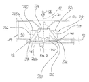
- Such a fan can be used for example in a radial fan, which in FIG. 5 is shown schematically.
- the impeller 10 is intended to be capable of handling fluids, in particular gaseous fluids, which may interfere with abrasive particles, e.g. Dust particles, water particles, snowflakes, fat particles and the like. Are loaded to pump effectively or pump out of an environment.
- abrasive particles e.g. Dust particles, water particles, snowflakes, fat particles and the like.
- Such fan wheels can also fulfill the task of largely separating these particles during the flow of the fan impeller.
- a specific field of application of the fan wheel is in the conveying / filtering function of fluids which have an extremely high proportion of entrained particles, wherein the wear on the fan wheel should be as low as possible.
- the fan 10 has a rotation axis 12, which - as can be seen from the FIG. 5 recognizes, which should already be referred to here - in the assembly in one Fan housing 14, for example, vertically aligned.
- the orientation of the axis 12 is arbitrary.
- a designated 16 hub rotatably seated on a drive shaft, not shown, with the axis 12 and it carries a blade support member 18, which extends substantially perpendicular to the axis of rotation 12.
- the carrier part 18, in turn, carries a blade arrangement with a large number of fan wheel blades 20 arranged in the manner of a wreath at a circumferential distance from each other and, as a rule, identically designed.
- the fan blades 20 are - as is apparent from the illustrations of FIGS. 1 and 4 yields - to an axis of rotation 12 containing axial plane 22, such as the plane of the FIG. 3 at a certain angle DELTA, so that they produce a radially outward flow when turning the fan 10 with the direction of rotation V.
- the angle DELTA can also be NULL.
- the fan blades are aligned parallel to the axis of rotation 12, but they can also be employed to the normal plane 15, which coincides in the embodiment shown with the plane of the support member 18, at an angle ⁇ 90 °, ie such that contained in the fluid to be conveyed particles under the influence of the dynamic forces, including the centrifugal and the Coriolis forces, are acted upon with a force component directed towards the support member.
- the fan blades 20 are straight. However, it should already be emphasized at this point that the blade shape can be modified as desired in order to improve the fluidic efficiency of the fan and / or the particle separation to be described later.
- the fan blades 20 each have a radially inner leading edge 24 and a radially outer trailing edge 26. Between the fan blades 20 substantially radially outwardly directed flow channels 28 are defined, so that therefore an axial inlet flow - in FIG. 5 denoted by the arrow SE - is at radially rotating fan 10 radially outward in an outlet flow SA with radial and directed in the circumferential direction speed component is deflected.
- leading edges 24 and flow outlet edges 26 each have a pitch circle 24a or 26a associated therewith.
- the flow entry edges 24 extend from a portion of the support member 18 proximate to the hub 16 and extend axially therefrom to a blade edge 29 substantially parallel to the support member 18 (see FIGS FIG. 3 ) or 229 (see FIG. 5 ).
- the blades carry on the side facing away from the support member 18, an annular disc 21 and they are firmly connected to this, for example, welded. You can also 20 just below a top wall of the housing 14 ends.
- the axial extent H of the fan blades 20 thus determined as a distance between the support member 18 and the annular disc 21st
- the shape of the Lüfterradschaufeln 20 may vary depending on the fan design - within wide limits.
- the construction of the fan wheel becomes stiffer, so that it is sufficient to attach the fan blades to the support member 18, e.g. to weld.
- the leading edge 24 of the fan blades can then be arranged substantially parallel to the axis of rotation.
- a freely cantilevered shape of the blades has the advantage that no particle accumulations are formed in the fan.
- the fan 10 is installed in the housing 14 of the Radialgebläseso that it comes to rest below an axial inlet funnel or inlet nozzle 30 which is aligned with the axis of rotation 12 of the fan 10. Radially from the outside, the fan 10 is enclosed by an annular channel 32 having an outlet 34 for the fluid.
- the annular channel 32 has a bottom surface 36 which closely conforms to the radially outer blade edges 26 while maintaining a small gap 37.
- the fan wheel 10 may also be provided with a bottom-side recess (not shown) into which the bottom surface 36 of the annular channel 32 engages with a fit.
- the bottom surface 36 of the annular channel 32 to a support member 18 nearest edge 38 of the fan blades 20 axially spaced by a predetermined gap MS.
- the bottom surface 36 of the annular channel 32 defines a radial or annular gap 40 for discharging particles deposited from the fluid, such as dust, water, oil or grease particles.
- the annular gap 40 is surrounded by a further annular chamber 42 for collecting and discharging the particles separated from the fluid.
- the additional blades 44 are employed against the direction of rotation V, ie they close with the normal plane 15 to the axis of rotation 12 and with the plane of the support member 18 at an angle WA> 90 °, which manages the wear of the fan blades 20 and possibly attached thereto strip-like projections in FIG. 1 indicated only by dashed lines and designated by 48, to even.
- the angle of attack WA can be up to 135 ° and is selected as a function of the particle size, weathering and consistency as well as the flow velocities in order to minimize the wear of the main blades.
- the additional blades 44 have an axial extent EA, which is less than the height H of the fan blades 20.
- the additional blades 44 have a height EA, which is up to 50%, preferably up to 30% of the axial extent H of the fan blades 20.
- the fan blades 20 as well as the additional blades 44 made of sheet steel, wherein the material is tuned according to the ambient conditions in Einz the radial fan.
- the material is tuned according to the ambient conditions in Einz the radial fan.
- other materials can be used, depending on which properties are required in the long-term use.
- the blades 20 and 44 are subject to different wear, so it is advantageous to keep the thickness D44 of the auxiliary blades larger than the thickness D20 of the main blades 20.
- the thickness of the fan blades 20, 120 and auxiliary blades 44, 144 not reproduced to scale. Contrary to the Dartellung in the Figures 2 and 3
- the thickness D44 of the auxiliary blades 44 is about three times the thickness D20 of the fan blades. That is, at a thickness D20 of the fan blades 20, for example, 5 mm (which is realistic for a fan of up to 1000 mm diameter) is the thickness D44 of the additional blades about 15 mm.
- additional blades 44 are offset to the fan blades 20 in the circumferential direction, in such a way that the deflected by the additional blades 44 particles under the influence of fluid mechanical and other dynamic forces do not hit the leading edges 24 of the fan blades 20 .
- the additional blades 44 may also overlap in the radial direction with the Lüfterradschaufeln 20.
- each fan blade 20 can carry on its working or pressure side 46 at least one strip-like projection 48, which is employed to the flow direction in the flow channel 28 between the blades 20 such that the flow axially at least in Druckhowmony to the support member 18 is deflectable and at a predetermined axial distance, preferably not greater than the dimension MS - see FIG. 5 - is, to the support member 18 ends.
- a strip-like projection 48 is provided at all, its height is kept rather small and should not exceed the dimension of 8 mm.
- the fan blades 120 are convex in the direction V.
- the Lüfterradschaufeln 120 are smooth, so that there is a good efficiency and low noise.
- each Lüfterradschaufel 220 namely on the respective working or printing side 246 two substantially mutually parallel strip-like projections 248a, 248b provided that terminate at a substantially same axial distance MS to the support member 218.
- An unillustrated angle of inclination, under which the projections 248a, 248b are made to the blade surface 246, can be set to a certain value, which is the composition of the fluid best in terms of wear minimization and / or Abscheide Angelsgrad.
- the angle of attack or the surface design (also an arch shape is possible) of the protrusions 248 is preferably determined empirically depending on the type and consistency of the particles to be filtered out of the fluid.
- the projections 248 are in the embodiment shown to the flow-leading edge 224 of the Lüfterradschaufeln 220 out, but they can also end in front of the edge 224.
- the fan blades 20 can also be made at an angle WS, which is smaller than 90 ° to the peripheral velocity vector, whereby the particles contained in the fluid, which may be in solid or liquid form, under the influence of the fluidic forces, the inertial forces and the other dynamic Forces such as centrifugal and Coriolis forces are urged towards the support member 18, so that in the area radially inside the annular gap 40 a significantly larger particle concentration is present than in the rest of the flow.
- the particles contained in this ströungs slaughter reach via the annular gap 40 in the annular chamber 42, which is preferably designed so that no excessive back pressure is built up therein.
- the main flow leaving the fan 10 above the annular gap 40 is cleaned to a correspondingly high percentage.
- the adjustability of the measure MS can be influenced by the degree of separation efficiency as a function of the composition of the fluid to be cleaned.
- Ach the angle of attack WS of the fan blades 20, 120, 220 can be varied with respect to the normal plane 15 to the axis of rotation 12 in the radial direction, so that there is a kind of propeller shape for the blades.
- the additional blades 144 as well as the fan blades 120 are convex. But they can also be straight or concave or S-shaped.
- the strip-like projections 248a, 248b may also or be given a different shape, for example, be guided arcuately.
- the invention thus provides an axial impinged radial impeller for conveying a particle-laden fluid, with a driven support member which extends substantially perpendicular to a rotation axis and carries a blade assembly with a plurality of annularly spaced circumferentially spaced impeller blades, each having a radially inward leading edge and a radially outer outlet edge and between which radially outwardly directed flow channels are fixed, whereby a axial inlet flow can be deflected radially outwards.
- the support carries radially within the fan blades additional axially projecting from the support member supporting blades, which are employed to the normal plane of the rotation axis such that in the fluid to be conveyed particles with a force component directed away from the carrier part can be acted upon.
Landscapes
- Engineering & Computer Science (AREA)
- Mechanical Engineering (AREA)
- General Engineering & Computer Science (AREA)
- Structures Of Non-Positive Displacement Pumps (AREA)
Abstract
Description
Die Erfindung betrifft ein axial angeströmtes Radial-Lüfterrad zum Fördern eines mit Partikeln beladenen Strömungsmittels, mit einem angetriebenen Trägerteil, das sich im Wesentlichen senkrecht zu einer Drehachse erstreckt und eine Schaufelanordnung mit einer Vielzahl von kranzartig im Umfangsabstand zueinander angeordneten Lüfterradschaufeln trägt, die jeweils eine radial innenliegende Anströmkante und eine radial außenliegende Austrittskante aufweisen und zwischen denen radial nach außen gerichtete Strömungskanäle festgelegt sind, wodurch eine axiale Eintrittströmung (SE) radial nach außen umlenkbar ist. gemäß dem Oberbegriff des Patentanspruchs 1.The invention relates to an axial impinged radial impeller for conveying a particle-laden fluid, with a driven support member which extends substantially perpendicular to a rotation axis and carries a blade arrangement with a plurality of annularly spaced circumferentially spaced impeller blades, each one radially have inner leading edge and a radially outer outlet edge and between which radially outwardly directed flow channels are fixed, whereby an axial inlet flow (SE) is deflected radially outward. according to the preamble of claim 1.
Derartige Lüfterräder sind beispielsweise aus den Dokumenten
Aus dem Dokument
Vorstehend beschriebene Lüfterräder werden vorrangig dort eingesetzt, wo es darum geht, aus einer Umgebung Strömungsmittel abzupumpen, das mit beträchtlichen Mengen von Partikeln in fester und/oder flüssiger Form beladen ist. Das mit dem Lüfterrad ausgestattete Radialgebläse hat auf der dem Trägerteil abgewandten Seite eine Eintrittsöffnung für das Fluid und das Lüfterrad trägt eine Schaufelanordnung in Form eines Schaufelkranzes, wobei zwischen den einzelnen Schaufeln Radialkanäle definiert werden, durch die das aus der axialen Richtung radial umgelenkte Fluid nach außen strömen und dort aus dem Laufrad austreten kann. In entsprechend ausgestatteten Radialgebläsen wird das Laufrad in der Regel in ein Gebläsegehäuse derart mit Passung eingebaut, dass es von einem Ringkanal mit einem Auslass umgeben ist.The impellers described above are primarily used where it is necessary to pump fluid from an environment that is loaded with substantial quantities of solid and / or liquid particles. The radial fan equipped with the fan has on the side facing away from the carrier part an inlet for the fluid and the fan carries a blade assembly in the form of a blade ring, between the individual blades radial channels are defined by the radially outwardly deflected from the axial direction fluid to the outside flow and can escape from the impeller there. In correspondingly equipped radial fans, the impeller is usually installed in a blower housing with such a fit that it is surrounded by an annular channel with an outlet.
Häufig sind die von derartigen Radialgebläsen zu fördernden Strömungsmittel bzw. Fluide mit abrasiven Stoffen, wie mit Feststoff versetzten Wasser- oder Fetttröpfchen oder Staubpartikel, beladen. Um diese Partikel aus der Fluidströmung abzuscheiden, können grundsätzlich Filter vor- oder nachgeschaltet werden. Diese Filter haben aber den Nachteil, dass sie aufwendig gewartet werden müssen, um den Druckabfall in der Strömung in erträglichen Grenzen zu halten. Damit der Aufwand beim Abscheiden der Partikel klein und dennoch der Abscheide- und Förderwirkungsgrad auf hohem Niveau gehalten werden kann, wird den Lüfterrädern die Aufgabe übertragen, diese Partikel - zumindest teilweise - bereits beim Durchströmen des Lüfterrads vor dem Austreten aus dem Gebläse wirksam abzuscheiden.Frequently, the fluids or fluids to be delivered by such radial fans are abrasive materials, such as solid or suspended water droplets or dust particles loaded. In order to separate these particles from the fluid flow, filters can always be upstream or downstream. But these filters have the disadvantage that they must be maintained consuming to keep the pressure drop in the flow within tolerable limits. So that the expense of depositing the particles can be kept small and yet the separation and delivery efficiency at a high level, the fan wheels are given the task to effectively deposit these particles - at least in part - as it flows through the fan before exiting the fan.
Zu diesem Zweck sind gemäß
Gemäß
Diese bekannten Lüfterräder haben allerdings häufig eine nur unzureichende Standzeit, da die im Strömungsmittel enthaltenen Partikel zu punktuellem hohen Verschleiß führen, der zu einem frühzeitigen Austausch der Lüfterräder führt. Dieser Verschleiß ist häufig an der Schaufelwurzel, d.h. an der Schaufelkante im Übergang zum Trägerteil besonders groß.However, these known fan wheels often have only insufficient service life, since the particles contained in the fluid lead to punctual high wear, which leads to an early replacement of the fan wheels. This wear is common at the blade root, i. particularly large at the blade edge in the transition to the carrier part.
Der Erfindung liegt deshalb die Aufgabe zugrunde, ein Radial-Lüfterrad der eingangs beschriebenen Art in der Weise weiterzubilden, dass die Standzeit wesentlich erhöht werden kann, insbesondere dann, wenn die zu fördernden Strömungsmittel mit abrasiven Partikeln belastet sind.The invention is therefore the object of developing a radial impeller of the type described above in such a way that the service life can be significantly increased, especially if the fluid to be pumped are loaded with abrasive particles.
Diese Aufgabe wird durch die Merkmale des Anspruchs 1 gelöst.This object is solved by the features of claim 1.
Erfindungsgemäß wird das Trägerteil radial innerhalb der Lüfterradschaufeln mit zusätzlichen, vom Trägerteil axial vorstehenden Zusatzschaufeln bestückt, die zur Normalebene der Drehachse derart angestellt sind, dass in dem zu fördernden Fluid enthaltene Partikel mit einer vom Trägerteil weg gerichteten Kraftkomponente beaufschlagbar sind. Es konnte in Versuchen gezeigt werden, dass sich mit dieser Maßnahme die Standzeit des Lüfterrads um das 2- bis 5-fache steigern lässt.According to the invention, the support member is fitted radially within the fan blades with additional axially projecting from the support member additional blades, which are employed to the normal plane of the rotation axis such that in the fluid to be delivered Particles are acted upon with a directed away from the carrier part force component. It could be shown in tests that the service life of the fan wheel can be increased by 2 to 5 times with this measure.
Vorteilhafte Weiterbildungen sind Gegenstand der Unteransprüche.Advantageous developments are the subject of the dependent claims.
Wenn die Lüfterradschaufeln und/oder die Zusatzschaufeln in Drehrichtung des Lüfterrads konvex, konkav oder S-förmig gekrümmt sind, lassen sich die strömungsmechanischen Eigenschaften des Lüfterrads verbessern.If the fan blades and / or the additional blades in the direction of rotation of the fan are curved convex, concave or S-shaped, the flow characteristics of the fan can be improved.
Wenn die Zusatzschaufeln zu den Lüfterradschaufeln in Umfangsrichtung versetzt sind oder sogar mit den Lüfterradschaufeln in radialer Richtung überlappen, erfolgt eine weiter verbesserte Schonung der Lüfterradschaufeln vor Verschleiß.If the auxiliary blades are circumferentially offset to the fan blades or even overlap with the fan blades in the radial direction, further improved protection of the fan blades from wear occurs.
Die Zusatzschaufeln können eine Höhe haben, die sich in radialer Richtung ändert. Auf diese Weise werden die strömungsmechanischen Verluste minimiert.The additional blades may have a height that varies in the radial direction. In this way, the fluidic losses are minimized.
Wenn die Zusatzschaufeln aus einem verschleißfesten Werkstoff bestehen, lässt sich die Standzeit des Lüfterrads weiter anheben. Vorzugsweise sind die Zusatzschaufeln austauschbar, so dass die Lebensdauer des Lüfterrads noch weiter verbessert wird. Eine andere Maßnahme zur Steigerung der Einsatzdauer des Radial-Lüfterrads besteht darin, die Dicke bzw. die Blechstärke der Zusatzschaufeln größer zu machen als diejenige der Lüfterrad-Hauptschaufeln, beispielsweise um den Faktor 3.If the additional blades are made of a wear-resistant material, the service life of the fan wheel can be further increased. Preferably, the additional blades are interchangeable, so that the life of the fan is further improved. Another measure for increasing the service life of the radial impeller is to make the thickness or the sheet thickness of the additional blades larger than that of the fan main blades, for example by a factor of 3.
Vorzugsweise haben die Zusatzschaufeln eine maximale axiale Erstreckung, die geringer ist als die der Lüfterradschaufeln, wodurch sich die Strömungsverluste weiter verringern lassen. Versuche haben gezeigt, dass es besonders vorteilhaft ist, die axiale Erstreckung der Zusatzschaufeln auf etwa 30% der axialen Erstreckung der Lüfterradschaufeln zu beschränken.Preferably, the auxiliary blades have a maximum axial extent which is less than that of the fan blades, whereby the flow losses can be further reduced. Experiments have shown that it is particularly advantageous to limit the axial extent of the additional blades to about 30% of the axial extent of the fan blades.
Ein erfindungsgemäßes Radialgebläse, das mit einem erfindungsgemäßen Lüfterrad ausgestattet ist, ist Gegenstand der Ansprüche 14 bis 17. Dieses Radialgebläse kann gleichzeitig einen variablen Prozentsatz von im Strömungsmittel enthaltenen festen oder flüssigen Partikeln durch den Ringkanal mit dem Auslass abscheiden.A radial fan according to the invention, which is equipped with a fan according to the invention is the subject of
Wenn das Spaltmaß MS des Radialkanals einstellbar ist, lässt sich das Radialgebläse optimal an die Qualität des zu fördernden Strömungsmittels anpassen.If the gap dimension MS of the radial channel is adjustable, the radial fan can be optimally adapted to the quality of the fluid to be delivered.
Die Erfindung lässt sich mit verschiedensten Konstruktionen des Lüfterrads kombinieren, einschließlich solcher, bei denen den Lüfterrädern eine verbesserte Abscheidewirkung übertragen wird.The invention can be combined with various designs of the fan wheel, including those in which the fan wheels an improved separation efficiency is transmitted.
Um bei größtmöglichem Verschleißschutz einen gewissen, verbesserten Abscheidungsgrad von Partikeln dann zu erzielen, wenn das zu fördernde und gleichzeitig zu reinigende Strömungsmittel mit großen Partikelmengen belastet ist, können die Lüfterradschaufeln zur Normalebene der Drehachse unter einem solchen Anstellwinkel angestellt bzw. schräg gestellt, dass in dem zu fördernden Fluid enthaltene Partikel unter dem Einfluss der Zentrifugal- und der Corioliskraft mit einer zum Trägerteil hin gerichteten Kraftkomponente beaufschlagbar sind. Damit werden die im Fluid enthaltenen Partikel während des Durchströmens des Lüfterrads bzw. der zwischen den Lüferradschaufeln ausgebildeten Strömungskanäle direkt in den Bereich nahe des Trägerteils gedrängt, so dass sie am radial äußeren Ende des Trägerteils, also beim Verlassen des Lüfterrads, über den Abscheide-Ringspalt von der Fluidströmung abgeschieden werden können. Wenn der Anstellwinkel der Lüfterradschaufeln bezüglich der Normalebene zur Drehachse in radialer Richtung variiert, kann der Abscheideeffekt weiter optimiert werden.In order to achieve a certain, improved degree of separation of particles with the greatest possible wear protection when the fluid to be pumped and at the same time is loaded with large amounts of particles, the fan blades can be adjusted to the normal plane of the rotation axis at such an angle or obliquely that in the Particles to be delivered fluid can be acted upon under the influence of centrifugal and Coriolis force with a force component directed towards the carrier part. Thus, the particles contained in the fluid during flow through the fan or the trained between the Lüferradschaufeln flow channels are urged directly into the area near the support member, so that they at the radially outer end of the support member, ie when leaving the fan, on the separation annular gap can be separated from the fluid flow. If the angle of attack of the fan blades with respect to the normal plane to the axis of rotation varies in the radial direction, the deposition effect can be further optimized.
Es hat sich in Versuchen gezeigt, dass bei extrem hoch mit Partikeln belasteten Strömungsmitteln Abscheidewirkungsgrade erzielbar sind, die weit über denjenigen liegen, welche mit herkömmlichen Konstruktionen realisiert werden konnten.It has been shown in experiments that with extremely highly particle-loaded fluids separation efficiencies can be achieved, which are far above those which could be realized with conventional constructions.
Dabei ergibt sich der zusätzliche Vorteil, dass das erfindungsgemäße Lüfterrad leiser und mit einem höheren strömungsmechanischen Wirkungsgrad arbeitet, als die mit zusätzlichen Leitflächen ausgestatteten Lüfterräder, und dennoch nicht zu örtlichen Partikelansammlungen neigt, wodurch sich der Wartungsaufwand hearbsetzen lässt. Auf diese Weise eignet sich das erfindungsgemäße Lüfterrad auch bedingt für das grobe Reinigen von Strömungsmitteln, die mit einem Mix aus flüssigen und festen Partikeln beladen sind.This results in the additional advantage that the impeller according to the invention operates quieter and with a higher fluidic efficiency, as equipped with additional fins fan wheels, and yet not prone to local particle accumulation, which can be hearbsetzen the maintenance. In this way, the fan according to the invention is also suitable for the coarse cleaning of fluids that are loaded with a mix of liquid and solid particles.
Wenn die Schaufeln der Schaufelanordnung einen Schaufelkranz mit radial innenliegenden Strömungs-Eintrittskanten und radial außenliegenden Strömungs-Austrittskanten bilden, wobei den Strömungs-Eintrittskanten und Strömungs-Austrittskanten jeweils ein Teilkreis zugeordnet ist, ergibt sich ein rotationssymmetrischer Aufbau des Lüfterrads, wodurch die Herstellungskosten gesenkt werden können.If the blades of the blade assembly form a blade ring with radially inward flow inlet edges and radially outer flow outlet edges, wherein the flow inlet edges and flow outlet edges each having a pitch circle associated, there is a rotationally symmetrical structure of the fan, whereby the manufacturing cost can be reduced ,
Wenn sich die Strömungs-Eintrittskanten von einem Nabenabschnitt des Trägerteils ausgehend von diesem axial weg bis zu einer zum Trägerteil im Wesentlichen parallel verlaufenden Schaufelkante erstrecken, ergibt sich - neben einem für die Fluidströmung günstigen Strömungskanal, der in radialer Richtung eine im Wesentlichen gleichbleibende Höhe hat - eine besonders kompakte Form des Lüfterrads, das mit geringem Aufwand in ein Gebläsegehäuse eingebaut werden kann.If the flow inlet edges extend from a hub portion of the carrier part axially away from the latter to a blade edge extending essentially parallel to the carrier part, a flow channel which is favorable for the fluid flow and has a substantially constant height in the radial direction results, a particularly compact form of the fan, which can be installed with little effort in a fan housing.
Gerade bzw. nicht gekrümmte Lüfterradschaufeln haben bei bestimmten Partikelgrößen und/oder -verteilungen Vorteile hinsichtlich der Wartungsfreundlichkeit, da sie der Tendenz zu Partikelablagerungen entgegen wirken. Ein besonders hoher strömungsmechanischer Wirkungsgrad des Lüfterrads ergibt sich allerdings dann, wenn die Lüfterradschaufeln in Drehrichtung des Lüfterrads konvex gekrümmt sind.Straight or non-curved fan blades, with certain particle sizes and / or distributions, have advantages in terms of ease of maintenance, as they counteract the tendency for particle deposits. However, a particularly high degree of fluid-mechanical efficiency of the fan wheel arises when the fan wheel blades are curved in a convex manner in the direction of rotation of the fan wheel.
Das Lüfterrad kann zusätzlich dahingehend modifiziert werden, dass jede Lüfterradschaufel auf ihrer Arbeits- bzw. Druckseite zumindest einen leistenartigen Vorsprung erhält, der zur Strömungsrichtung im Strömungskanal zwischen den Schaufeln derart angestellt ist, dass die Strömung zumindest in Druckseitennähe axial auf das Trägerteil zu ablenkbar ist, wobei der leistenartige Vorsprung in vorbestimmtem und kleinem axialen Abstand zum Trägerteil endet. Mit diesen Vorsprüngen lassen sich kleine flüssige Partikel wirksam abscheiden. Aufgrund der erfindungsgemäßen Zusatzschaufeln gelingt es, den Verschleiß an derartigen Vorsprüngen wirksam einzudämmen, selbst wenn die Höhe der Vorsprünge beträchtlich sein sollte. Wenn allerdings die Höhe H im mm-Bereich liegt, kann die Geräuschentwicklung eingeschränkt und gleichzeitig ein besserer Wirkungsgrad erzielt werden.The impeller may additionally be modified to the effect that each impeller blade receives on its working or pressure side at least a strip-like projection which is employed to the flow direction in the flow channel between the blades such that the flow is axially deflectable at least in printing side proximity to the support member, wherein the strip-like projection terminates at a predetermined and small axial distance from the carrier part. With these projections, small liquid particles can be deposited effectively. Due to the additional blades according to the invention, it is possible to effectively control the wear on such projections, even if the height of the projections should be considerable. However, if the height H is in the mm range, the noise can be limited and at the same time a better efficiency can be achieved.
Wenn das Trägerteil von einer Platte gebildet ist, wird die Konstruktion des Lüfterrads und damit des Radialgebläses weiter vereinfacht, mit dem besonderen Vorteil, dass das Trägerteil im Betrieb nicht zu Partikelansammlungen auf seiner Oberseite neigt.If the carrier part is formed by a plate, the construction of the fan wheel and thus of the radial fan is further simplified, with the particular advantage that the carrier part in operation does not tend to particle accumulations on its top.
Wenn die Lüfterradschaufeln auf der dem Trägerteil abgewandeten Seite einen Ring tragen und mit diesem fest verbunden, beispielsweise verschweißt sind, kann die Stabilität des Lüfterrads angehoben werden, mit der Folge, dass das Trägerteil und/oder die Nabe leichter ausgeführt werden und eine Verbindung der Lüfterradschaufeln mit der Nabe entfallen kann.If the fan blades on the side facing away from the support member wearing a ring and fixedly connected to this, for example, welded, the stability of the fan can be raised, with the result that the support member and / or the hub are made easier and a compound of the fan blades can be omitted with the hub.
Ein erfindungsgemäßes Radialgebläse, das mit einem erfindungsgemäßen Lüfterrad ausgestattet ist, ist Gegenstand des Ansprüche 14 bis 17.An inventive radial fan, which is equipped with a fan according to the invention is the subject of
Weitere vorteilhafte Ausgestaltungen sind Gegenstand der übrigen Unteransprüche.Further advantageous embodiments are the subject of the remaining dependent claims.
Nachstehend werden anhand schematischer Zeichnungen Ausführungsformen der Erfindung näher erläutert. Es zeigen:
-
Figur 1 eine schematische Draufsicht eines Lüfterrads; -
Figur 2 den schematischen Schnitt gemäß II-II inFigur 1 ; -
Figur 3Figur 1 ; -
Figur 4 eine Draufsicht auf ein modifiziertes Lüfterrad gemäß der Erfindung; und -
Figur 5 eine schematische Schnittansicht des Radialgebläses mit einem Lüfterrad ähnlich demjenigen derFiguren 1 bis 4 .
-
FIG. 1 a schematic plan view of a fan wheel; -
FIG. 2 the schematic section according to II-II inFIG. 1 ; -
FIG. 3 the schematic sectional view according to III-III inFIG. 1 ; -
FIG. 4 a plan view of a modified fan according to the invention; and -
FIG. 5 a schematic sectional view of the radial fan with a fan similar to that ofFIGS. 1 to 4 ,
In den
Das Lüfterrad 10 soll dabei in der Lage sein, Strömungsmittel, insbesondere gasförmige Strömungsmittel, die mit abrasiv wirkenden Partikeln, wie z.B. Staubpartikeln, Wasserpartikeln, Schneeflocken, Fettpartikeln und dgl. beladen sind, effektiv zu fördern bzw. aus einer Umgebung abzupumpen. Solche Lüfterräder können darüber hinaus die Aufgabe erfüllen, diese Partikel beim Durschströmen des Lüfterrads weitgehend abzuscheiden. Ein spezifisches Anwendungsgebiet des Lüfterrads liegt in der Förder-/Filterfunktion von Strömungsmitteln, die einen extrem hohen Anteil an mitgeführten Partikeln haben, wobei der Verschleiß am Lüfterrad möglichst gering sein soll.The impeller 10 is intended to be capable of handling fluids, in particular gaseous fluids, which may interfere with abrasive particles, e.g. Dust particles, water particles, snowflakes, fat particles and the like. Are loaded to pump effectively or pump out of an environment. Such fan wheels can also fulfill the task of largely separating these particles during the flow of the fan impeller. A specific field of application of the fan wheel is in the conveying / filtering function of fluids which have an extremely high proportion of entrained particles, wherein the wear on the fan wheel should be as low as possible.
Das Lüfterrad 10 hat eine Drehachse 12, die - wie man anhand der
Eine mit 16 bezeichnete Nabe sitzt drehfest auf einer nicht gezeigten Antriebswelle mit der Achse 12 und sie trägt ein Schaufel-Trägerteil 18, das sich im Wesentlichen senkrecht zur Drehachse 12 erstreckt. Das Trägerteil 18 trägt seinerseits eine Schaufelanordnung mit einer Vielzahl von kranzartig im Umfangsabstand zueinander angeordneten und in der Regel identisch ausgebildeten Lüfterradschaufeln 20.A designated 16 hub rotatably seated on a drive shaft, not shown, with the
Die Lüfterradschaufeln 20 sind - wie sich aus den Darstellungen der
Die Lüfterradschaufeln sind zur Drehachse 12 parallel ausgerichtet, sie können aber auch zur Normalebene 15, die bei dem gezeigten Ausführungsbeispiel mit der Ebene des Trägerteils 18 zusammenfällt, unter einem Anstellwinkel < 90° , d.h derart angestellt sein, dass in dem zu fördernden Fluid enthaltene Partikel unter dem Einfluss der dynamischen Kräfte, einschließlich der Zentrifugal- und der Corioliskräfte, mit einer zum Trägerteil hin gerichteten Kraftkomponente beaufschlagbar sind.The fan blades are aligned parallel to the axis of
Bei dem gezeigten Ausführungsbeispiel der
Die Lüfterradschaufeln 20 haben jeweils eine radial innenliegende Anströmkante 24 und eine radial außenliegende Austrittskante 26. Zwischen den Lüfterradschaufeln 20 werden im Wesentlichen radial nach außen gerichtete Strömungskanäle 28 definiert, so dass also eine axiale Eintrittströmung - in
Wie die Figuren zeigen, ist den Anströmkanten 24 und Strömungs-Austrittskanten 26 jeweils ein Teilkreis 24a bzw 26a zugeordnet. Die Strömungs-Eintrittskanten 24 gehen von einem der Nabe 16 nahe liegenden Abschnitt des Trägerteils 18 aus und erstrecken sich von diesem axial weg bis zu einer zum Trägerteil 18 im Wesentlichen parallel verlaufenden Schaufelkante 29 (siehe
Bei der Ausführungsform nach den Figuren tragen die Schaufeln auf der dem Trägerteil 18 abgewandeten Seite eine Ringscheibe 21 und sie sind mit dieser fest verbunden, beispielsweise verschweißt. Sie lönnen aber auch 20 knapp unterhalb einer Deckwand des Gehäuses 14 enden. Die axiale Erstreckung H der Lüfterradschaufeln 20 bestimmt sich also als Abstand zwischen dem Trägerteil 18 und der Ringscheibe 21.In the embodiment according to the figures, the blades carry on the side facing away from the
Die Formgebung der Lüfterradschaufeln 20 kann -je nach Lüfterkonstruktion - in weiten Grenzen variieren. Wenn die Lüfterradschaufeln 20 - wie in den Figuren gezeigt - eine formstabile Ringscheibe 21 tragen, wird die Konstruktion des Lüfterrads steifer, so dass es genügt, die Lüfterradschaufeln am Trägerteil 18 zu befestigen, wie z.B. anzuschweißen. Die Anströmkante 24 der Lüfterradschaufeln kann dann im Wesentlichen parallel zur Drehachse angeordnet werden. Andererseits hat eine frei auskragende Form der Schaufeln den Vorteil, dass das sich im Gebläse keine Partikelansammlungen bilden.The shape of the
Generell liegen also die Strömungs-Eintrittskanten 24 der Lüfterradschaufeln 20 in den verschiedenen Schnittansichten senkrecht zur Drehachse 12 auf Teilkreisen 24a, die Bestandteil einer Teilkreisschar sind, welche einen Zylinder- oder Kegelstumpfmantel mit einem kleinen Kegelwinkel WK (siehe
Wie sich aus der
Der Ringkanal 32 hat eine Bodenfläche 36, die sich eng - unter Einhaltung eines kleinen Spalts 37 - an die radial außenliegenden Schaufelkanten 26 anschmiegt. Zu diesem Zweck kann das Lüfterrad 10 auch mit einer - nicht gezeigten - bodenseitigen Eindrehung versehen sein, in die mit Passung die Bodenfläche 36 des Ringkanals 32 eingreift. Wie sich weiter aus der
Der Ringspalt 40 ist von einer weiteren Ringkammer 42 zum Sammeln und Abführen der aus dem Fluid abgeschiedenen Partikel umgeben.The
Am Trägerteil 18 bzw. an der Nabe 16 sind radial innerhalb der Lüfterradschaufeln 20 zusätzliche, vom Trägerteil 18 axial vorstehende Zusatzschaufeln 44 angebracht, wobei die axiale Erstreckung der Zusatzschaufeln geringer ist als die der Lüfterradschaufeln 20. Die Zusatzschaufeln 44 sind gegen die Drehrichtung V angestellt, d.h. sie schließen mit der Normalebene 15 zur Drehachse 12 bzw. mit der Ebene des Trägerteils 18 einen Winkel WA >90° ein, wodurch es gelingt, den Verschleiß der Lüfterradschaufeln 20 und von gegebenenfalls daran angebrachten leistenartigen Vorsprüngen, die in
Die Zusatzschaufeln 44 haben eine axiale Erstreckung EA, die geringer ist als die Höhe H der Lüfterradschaufeln 20. Vorzugsweise haben die Zusatzschaufeln 44 eine Höhe EA, die bis zu 50%, vorzugsweise bis zu 30% der axialen Erstreckung H der Lüfterradschaufeln 20 beträgt.The
In vielen Fällen bestehen die Lüfterradschaufeln 20 ebenso wie die Zusatzschaufeln 44 aus Stahlblech, wobei der Werkstoff entsprechend den Umgebungsbedingungen im Einstz des Radial-Lüfterrads abgestimmt wird. Es können selbstverständlich andere Materialien verwendet werden, je nach dem, welche Eigenschaften im Langzeiteinsatz gefordert sind.In many cases, the
Die Schaufeln 20 und 44 sind unterschiedlichem Verschleiß ausgesetzt, so dass es von Vorteil ist, die Dicke D44 der Zusatzschaufeln größer zu halten als diejenige Dicke D20 der Hauptschaufeln 20. In den schematischen Zeichnungen ist die Dicke der Lüfterradschaufeln 20, 120 und Zusatzschaufeln 44, 144 nicht maßstabsgetreu wiedergegeben. Entgegen der Dartellung in den
Um die Wirkung der Zusatzschaufeln 44 möglichst groß zu halten, sind sie zu den Lüfterradschaufeln 20 in Umfangsrichtung versetzt, und zwar derart, dass die von den Zusatzschaufeln 44 abgelenkten Partikel unter Einwirkung der strömungsmechanischen und sonstigen dynamischen Kräfte nicht auf die Anströmkanten 24 der Lüfterradschaufeln 20 treffen. Die Zusatzschaufeln 44 können sich auch in radialer Richtung mit den Lüfterradschaufeln 20 überlappen.To keep the effect of the
Wie in
Mit dieser Gestaltung des Lüfterrads ergibt sich die folgende Arbeitsweise des Radialgebläses:
- Das zu einem hohen Prozentsatz mit Partikeln beladene Strömungsmittel, vorzugsweise gasförmige Strömungsmittel, wie etwa Luft, strömt bei 30 in das Radialgebläse ein. Durch die Wirkung der Lüfterradschaufeln 20 des mit vorgegebener Drehzahl rotierenden Lüfterrads 10 wird die Strömung in
die Kanäle 28 umgelenkt und radial nach außen gefördert. Durch die erfindungsgemäßen Zusatzschaufeln 44 und deren erfindungsgemäße Anstellung unter dem Winkel WA>90° lässt sich der durch die Partikel hervorgerufene Verschleiß am Lüfterrad 10 vergleichmäßigen. Insbesondere die hoch beanspruchten Schaufelwurzeln 50der Lüfterradschaufeln 20, aber auch dieSchaufelwurzeln 52der Zusatzschaufeln 44 lassen sich wirksam vor übermäßigem und schnellen Verschleiß schützen.
- The highly particulate laden fluid, preferably gaseous fluid, such as air, enters the radial fan at 30. By the action of the
fan blades 20 of the rotating at a predetermined speed fan wheel 10, the flow is deflected into thechannels 28 and conveyed radially outward. Due to theadditional blades 44 according to the invention and their employment according to the invention at an angle WA> 90 °, the wear caused by the particles on the fan wheel 10 can be evened out. In particular, the highly stressedblade roots 50 of thefan blades 20, but also theblade roots 52 of theadditional blades 44 can be effectively protected against excessive and rapid wear.
Dabei sind die Strömungsverluste im Lüfterrad 10 aufgrund der glatten Ausgestaltung der Strömungswege, sehr gering, was auch für die Geräuschentwicklung zutrifft. Ferner neigt das Lüfterrad 10 nicht zu Partikelablagerungen, so dass sich über eine lange Betriebsdauer hinweg ein wartungsfreier Betrieb selbst dann ergibt, wenn die Partikel sehr abrasiv sind und/oder zum Zusammenkleben neigen.The flow losses in the fan 10 due to the smooth design of the flow paths, very low, which also applies to the noise. Furthermore, the fan 10 does not tend to particle deposits, so that about Maintenance-free operation for a long period of operation even if the particles are very abrasive and / or tend to stick together.
Vortshend wurde eine Ausführungsform mit geraden Lüfterradschaufeln 20 und Zusatzschaufeln 44 beschrieben. Unter Bezug auf die
Bei der in
Bei der in
Ein nicht näher dargestellter Neigungswinkel, unter dem die Vorsprünge 248a, 248b zur Schaufelfläche 246 angestellt sind, kann auf einen bestimmten Wert eingestellt werden, der der Zusammensetzung des Strömungsmittels am besten hinsichtlich Verschleißminimierung und/oder Abscheidewirkungsgrad gerecht wird. Der Anstellwinkel bzw. die Oberflächengestaltung (auch eine Bogenform ist möglich) der Vorprünge 248 wird vorzugsweise empirisch je nach Art und Konsistenz der aus dem Fluid heraus zu filternden Partikel festgelegt wird.An unillustrated angle of inclination, under which the
Die Vorsprünge 248 sind bei der gezeigten Ausführungsform bis zur Strömungs-Eintrittskante 224 der Lüfterradschaufeln 220 geführt, sie können aber auch vor der Kante 224 enden.The projections 248 are in the embodiment shown to the flow-leading
Wie sich ferner aus der
Selbstverständlich sind weitere Abwandlungen des Lüfterrads und des Radialgebläses möglich, ohne den Grundgedanken der Erfindung zu verlassen.Of course, further modifications of the fan and the radial fan are possible without departing from the spirit of the invention.
Die Lüfterradschaufeln 20 können auch unter einem Winkel WS, der kleiner als 90° ist, zum Umfangsgeschwindigkeitsvektor angestellt werden, wodurch die im Strömungsmittel enthaltenen Partikel, die in fester oder flüssiger Form vorliegen können, unter Einwirkung der strömungsmechanischen Kräfte, der Massenkräfte und der sonstigen dynamischen Kräfte, wie der Zentrifugal- und der Corioliskräfte, in Richtung auf das Trägerteil 18 zu gedrängt werden, so dass im Bereich radial innerhalb des Ringspalts 40 eine erhebliche größere Partikelkonzentration vorliegt als in der übrigen Strömung. Die in dieser Ströungsschicht enthaltenen Partikel gelangen über den Ringspalt 40 in die Ringkammer 42, die vorzugsweise so ausgebildet ist, dass darin kein übermäßiger Staudruck aufgebaut wird. Die Hauptströmung, die das Lüfterrad 10 oberhalb des Ringspalts 40 verlässt, ist zu einem entsprechend hohen Prozentsatz gereinigt. Über eine Einstellbarkeit des Maßes MS lässt sich der Abscheidewirkungsgrad in Abhängigkeit von der Zusammensetzung des zu reinigenden Strömungsmittels beeinflussen.The
Ach kann der Anstellwinkel WS der Lüfterradschaufeln 20, 120, 220 bezüglich der Normalebene 15 zur Drehachse 12 in radialer Richtung variiert werden, so dass sich für die Schaufeln eine Art Propellerform ergibt.Ach the angle of attack WS of the
Bei dem Ausführungsbeispiel der
Die leistenartigen Vorsprüngen 248a, 248b können auch oder eine andere Form erhalten, beispielsweise bogenförmig geführt sein.The strip-
Als Material für die Komponenten des Lüfterrads können alle gängigen Werkstoffe, wie z.B. metallische Werkstoffe und Kunststoffe verwendet werden. Es können Fügetechniken, wie z.B. Schweiß- oder Klebetechniken, aber auch Gusskonstruktionen Anwendung finden.As material for the components of the fan, all common materials, such. metallic materials and plastics are used. Joining techniques, e.g. Welding or gluing techniques, but also found casting designs application.
Die Erfindung schafft somit ein axial angeströmtes Radial-Lüfterrad zum Fördern eines mit Partikeln beladenen Strömungsmittels, mit einem angetriebenen Trägerteil, das sich im Wesentlichen senkrecht zu einer Drehachse erstreckt und eine Schaufelanordnung mit einer Vielzahl von kranzartig im Umfangsabstand zueinander angeordneten Lüfterradschaufeln trägt, die jeweils eine radial innenliegende Anströmkante und eine radial außenliegende Austrittskante aufweisen und zwischen denen radial nach außen gerichtete Strömungskanäle festgelegt sind, wodurch eine axiale Eintrittströmung radial nach außen umlenkbar ist. Um die Bestandteile des Lüfterrads wirksam vor Verschleiß zu schützen und die Labensdauer des Lüfterrads anzuheben, trägt das Trägerteil radial innerhalb der Lüfterradschaufeln zusätzliche vom Trägerteil axial vorstehende Zusatzschaufeln trägt, die zur Normalebene der Drehachse derart angestellt sind, dass in dem zu fördernden Fluid enthaltene Partikel mit einer vom Trägerteil weg gerichteten Kraftkomponente beaufschlagbar sind.The invention thus provides an axial impinged radial impeller for conveying a particle-laden fluid, with a driven support member which extends substantially perpendicular to a rotation axis and carries a blade assembly with a plurality of annularly spaced circumferentially spaced impeller blades, each having a radially inward leading edge and a radially outer outlet edge and between which radially outwardly directed flow channels are fixed, whereby a axial inlet flow can be deflected radially outwards. In order to effectively protect the components of the fan from wear and to increase the life of the fan, the support carries radially within the fan blades additional axially projecting from the support member supporting blades, which are employed to the normal plane of the rotation axis such that in the fluid to be conveyed particles with a force component directed away from the carrier part can be acted upon.
Claims (17)
Priority Applications (1)
| Application Number | Priority Date | Filing Date | Title |
|---|---|---|---|
| EP08151626A EP1961970A1 (en) | 2007-02-26 | 2008-02-19 | Radial fan and radial blower fitter with locking protection and radial fan |
Applications Claiming Priority (2)
| Application Number | Priority Date | Filing Date | Title |
|---|---|---|---|
| EP07003877A EP1961968A1 (en) | 2007-02-26 | 2007-02-26 | Radial fan wheel and radial fan incorporating the same with locking protection |
| EP08151626A EP1961970A1 (en) | 2007-02-26 | 2008-02-19 | Radial fan and radial blower fitter with locking protection and radial fan |
Publications (1)
| Publication Number | Publication Date |
|---|---|
| EP1961970A1 true EP1961970A1 (en) | 2008-08-27 |
Family
ID=38255197
Family Applications (2)
| Application Number | Title | Priority Date | Filing Date |
|---|---|---|---|
| EP07003877A Withdrawn EP1961968A1 (en) | 2007-02-26 | 2007-02-26 | Radial fan wheel and radial fan incorporating the same with locking protection |
| EP08151626A Withdrawn EP1961970A1 (en) | 2007-02-26 | 2008-02-19 | Radial fan and radial blower fitter with locking protection and radial fan |
Family Applications Before (1)
| Application Number | Title | Priority Date | Filing Date |
|---|---|---|---|
| EP07003877A Withdrawn EP1961968A1 (en) | 2007-02-26 | 2007-02-26 | Radial fan wheel and radial fan incorporating the same with locking protection |
Country Status (1)
| Country | Link |
|---|---|
| EP (2) | EP1961968A1 (en) |
Families Citing this family (3)
| Publication number | Priority date | Publication date | Assignee | Title |
|---|---|---|---|---|
| EP2143958A1 (en) | 2008-07-07 | 2010-01-13 | Josip Pavetic | Ventilator integrated into a tube |
| DE102015213006A1 (en) * | 2015-07-10 | 2017-01-12 | Mahle International Gmbh | blower assembly |
| CN106837823B (en) * | 2017-03-06 | 2023-06-20 | 昆山佰斯拓机械设备有限公司 | Multi-blade centrifugal ventilator with cylindrical noise reduction structure and noise reduction process thereof |
Citations (10)
| Publication number | Priority date | Publication date | Assignee | Title |
|---|---|---|---|---|
| US1739604A (en) * | 1927-02-14 | 1929-12-17 | Clarage Fan Company | Fan |
| FR1058690A (en) | 1951-07-21 | 1954-03-18 | Babcock & Wilcox France | Wheel for radial blower machine |
| GB894893A (en) | 1958-07-08 | 1962-04-26 | Svenska Flaektfabriken Ab | Improvements in centrifugal fans |
| US3104050A (en) | 1960-08-17 | 1963-09-17 | Richard W Coward | Blades for centrifugal fans and the like |
| DE1503650A1 (en) * | 1965-12-23 | 1969-03-13 | Meissen Turbowerke | Fan impeller for conveying dusty gases |
| DE2809597A1 (en) * | 1978-03-06 | 1979-10-04 | Konrad Reitz Maschinen U Appar | Radial air circulation fan for room - has central straight radial fixed blades and curved enclosing rotor blades |
| EP0372701A1 (en) | 1988-12-06 | 1990-06-13 | Johnston Engineering Limited | Improvements in road sweeping vehicles |
| EP0615069A1 (en) | 1993-03-09 | 1994-09-14 | RATIONAL GmbH | Fan rotor |
| DE10315341B4 (en) | 2003-04-03 | 2005-04-14 | Mkn Maschinenfabrik Kurt Neubauer Gmbh & Co. | Cooking device with a blower with radial impeller and separator |
| EP1530682B1 (en) | 2002-08-22 | 2006-05-31 | Rational AG | Fan impeller with integrated precipitation of fat particles, in particular for a cooking device |
-
2007
- 2007-02-26 EP EP07003877A patent/EP1961968A1/en not_active Withdrawn
-
2008
- 2008-02-19 EP EP08151626A patent/EP1961970A1/en not_active Withdrawn
Patent Citations (10)
| Publication number | Priority date | Publication date | Assignee | Title |
|---|---|---|---|---|
| US1739604A (en) * | 1927-02-14 | 1929-12-17 | Clarage Fan Company | Fan |
| FR1058690A (en) | 1951-07-21 | 1954-03-18 | Babcock & Wilcox France | Wheel for radial blower machine |
| GB894893A (en) | 1958-07-08 | 1962-04-26 | Svenska Flaektfabriken Ab | Improvements in centrifugal fans |
| US3104050A (en) | 1960-08-17 | 1963-09-17 | Richard W Coward | Blades for centrifugal fans and the like |
| DE1503650A1 (en) * | 1965-12-23 | 1969-03-13 | Meissen Turbowerke | Fan impeller for conveying dusty gases |
| DE2809597A1 (en) * | 1978-03-06 | 1979-10-04 | Konrad Reitz Maschinen U Appar | Radial air circulation fan for room - has central straight radial fixed blades and curved enclosing rotor blades |
| EP0372701A1 (en) | 1988-12-06 | 1990-06-13 | Johnston Engineering Limited | Improvements in road sweeping vehicles |
| EP0615069A1 (en) | 1993-03-09 | 1994-09-14 | RATIONAL GmbH | Fan rotor |
| EP1530682B1 (en) | 2002-08-22 | 2006-05-31 | Rational AG | Fan impeller with integrated precipitation of fat particles, in particular for a cooking device |
| DE10315341B4 (en) | 2003-04-03 | 2005-04-14 | Mkn Maschinenfabrik Kurt Neubauer Gmbh & Co. | Cooking device with a blower with radial impeller and separator |
Also Published As
| Publication number | Publication date |
|---|---|
| EP1961968A1 (en) | 2008-08-27 |
Similar Documents
| Publication | Publication Date | Title |
|---|---|---|
| DE102008038776B4 (en) | Process for the screening of a millbase fluid mixture and mill classifier | |
| DE68906658T2 (en) | ROAD CLEANING DEVICES. | |
| EP2386030B1 (en) | Centrifugal pump with a device for removing particles | |
| WO2006133577A1 (en) | Centrifugal pump | |
| DE4429473C2 (en) | Air classifier | |
| EP2143958A1 (en) | Ventilator integrated into a tube | |
| EP0638365B2 (en) | Method and device for separating fine-grained solids into two grain size fractions | |
| EP3335808B1 (en) | Classifying rotor for centrifugal air separator | |
| EP3263203A1 (en) | Backwash filter | |
| DE4208202A1 (en) | CENTRIFUGAL PUMP | |
| EP1961970A1 (en) | Radial fan and radial blower fitter with locking protection and radial fan | |
| EP1961967A1 (en) | Radial fan wheel and radial fan incorporating the same | |
| DE2757175C2 (en) | Pulper for processing waste paper and similar fiber material | |
| DE102012100438A1 (en) | Separator e.g. oil separator for lifting cylinder combustion engine mounted in vehicle, has gas passage aperture that is formed in gap of baffle wall with respect to radial direction of rotor axis towards closed region of other wall | |
| DE1274404B (en) | Separator for cleaning intake air | |
| AT404234B (en) | CLASSIFICATION WHEEL FOR A WINIFIFIER | |
| DE2556382C3 (en) | Centrifugal air classifier | |
| EP1961969A2 (en) | Radial fan wheel | |
| EP3670920A1 (en) | Cutting mechanism for a submersible waste water pump | |
| CH689004A5 (en) | Centrifugal pump. | |
| DE29515434U1 (en) | Micro vortex mill | |
| EP2556873B1 (en) | Condensate separator | |
| DE4326604C2 (en) | classifier | |
| EP4059624B1 (en) | Device and method for separating dusty materials | |
| LU102840B1 (en) | Cutting ring for a pump liquid loaded with solids |
Legal Events
| Date | Code | Title | Description |
|---|---|---|---|
| PUAI | Public reference made under article 153(3) epc to a published international application that has entered the european phase |
Free format text: ORIGINAL CODE: 0009012 |
|
| AK | Designated contracting states |
Kind code of ref document: A1 Designated state(s): AT BE BG CH CY CZ DE DK EE ES FI FR GB GR HR HU IE IS IT LI LT LU LV MC MT NL NO PL PT RO SE SI SK TR |
|
| AX | Request for extension of the european patent |
Extension state: AL BA MK RS |
|
| 17P | Request for examination filed |
Effective date: 20090223 |
|
| 17Q | First examination report despatched |
Effective date: 20090325 |
|
| AKX | Designation fees paid |
Designated state(s): AT BE BG CH CY CZ DE DK EE ES FI FR GB GR HR HU IE IS IT LI LT LU LV MC MT NL NO PL PT RO SE SI SK TR |
|
| STAA | Information on the status of an ep patent application or granted ep patent |
Free format text: STATUS: THE APPLICATION IS DEEMED TO BE WITHDRAWN |
|
| 18D | Application deemed to be withdrawn |
Effective date: 20100901 |