EP1961463A1 - Improved snowshoe - Google Patents
Improved snowshoe Download PDFInfo
- Publication number
- EP1961463A1 EP1961463A1 EP08354015A EP08354015A EP1961463A1 EP 1961463 A1 EP1961463 A1 EP 1961463A1 EP 08354015 A EP08354015 A EP 08354015A EP 08354015 A EP08354015 A EP 08354015A EP 1961463 A1 EP1961463 A1 EP 1961463A1
- Authority
- EP
- European Patent Office
- Prior art keywords
- sieve
- frame
- central platform
- plate
- snowshoe
- Prior art date
- Legal status (The legal status is an assumption and is not a legal conclusion. Google has not performed a legal analysis and makes no representation as to the accuracy of the status listed.)
- Granted
Links
Images


Classifications
-
- A—HUMAN NECESSITIES
- A63—SPORTS; GAMES; AMUSEMENTS
- A63C—SKATES; SKIS; ROLLER SKATES; DESIGN OR LAYOUT OF COURTS, RINKS OR THE LIKE
- A63C13/00—Snow shoes
- A63C13/003—Means thereof for preventing slipping, e.g. crampons, e.g. on frame or shoe plate
-
- A—HUMAN NECESSITIES
- A63—SPORTS; GAMES; AMUSEMENTS
- A63C—SKATES; SKIS; ROLLER SKATES; DESIGN OR LAYOUT OF COURTS, RINKS OR THE LIKE
- A63C13/00—Snow shoes
- A63C13/006—Shoe support thereof, e.g. plate, movable relative to the frame
-
- A—HUMAN NECESSITIES
- A63—SPORTS; GAMES; AMUSEMENTS
- A63C—SKATES; SKIS; ROLLER SKATES; DESIGN OR LAYOUT OF COURTS, RINKS OR THE LIKE
- A63C13/00—Snow shoes
- A63C13/008—Adjustable heel support therefor, e.g. climbing wedge
-
- A—HUMAN NECESSITIES
- A63—SPORTS; GAMES; AMUSEMENTS
- A63C—SKATES; SKIS; ROLLER SKATES; DESIGN OR LAYOUT OF COURTS, RINKS OR THE LIKE
- A63C9/00—Ski bindings
- A63C9/006—Ski bindings with a climbing wedge
-
- A—HUMAN NECESSITIES
- A63—SPORTS; GAMES; AMUSEMENTS
- A63C—SKATES; SKIS; ROLLER SKATES; DESIGN OR LAYOUT OF COURTS, RINKS OR THE LIKE
- A63C9/00—Ski bindings
- A63C9/08—Ski bindings yieldable or self-releasing in the event of an accident, i.e. safety bindings
- A63C9/0807—Ski bindings yieldable or self-releasing in the event of an accident, i.e. safety bindings for both towing and downhill skiing
Definitions
- the fixing plate is pivotally mounted relative to the sieve around a transverse axis disposed substantially at the head of the metatarsals.
- An opening, generally called window, is arranged through the screen to allow the passage of the forefoot when tilting the shoe forward during the stride.
- the invention aims to remedy these drawbacks by proposing a snowshoe allowing a natural, progressive and cushioned foot during walking, and decreasing the resistance to travel to limit the effect of drag.
- Another object is to provide a racket for natural walking without fatigue in cant without having to tilt the ankle transversely.
- the racket according to the invention is characterized in that the pivoting fastening plate is articulated on the frame of the sieve around a first transverse axis before connected by an intermediate transmission rod with a second transverse axis placed at the rear of said first axis so as to increase the angular deflection of the fixing plate due to a combined pivotal movement about said first and second axes.
- the two longitudinal side members, or longitudinal side arms, which constitute the sides of the peripheral frame join together at the rear end of the racket to form the rear loop of the frame which is then a frame closed device.
- the two longitudinal side members, or longitudinal side arms, which constitute the sides of the sieve do not meet with each other at the rear end of the racket and the peripheral frame of the sieve is then opened in general shape of U when viewed in top view.
- the central platform of the sieve whose width is less than the width of the sieve, extends in the longitudinal direction of the racket from the rear end of the window through which the forefoot pivots when the step, to the rear end of the sieve when the peripheral frame is of the open type or close to the rear loop of the peripheral frame when the latter is of the closed type.
- the lower face of the central platform advantageously comprises prominent elements as spikes, the tips of which at least some are protruding from the lower edges of the sieve, the plane passing through the tips of said crampons, constituting the support plane of the racket on hard ground, is therefore at a level lower than that occupied by the general plane passing through the edges lower longitudinal sieve which we will consider as the support plane of the sieve on deep snow.
- the central platform of the sieve may be integral with the peripheral frame of the sieve with which it forms a rigid assembly.
- the central platform and the frame of the sieve constitute two distinct subassemblies interconnected by elastically deformable means, and / or by rigid mechanical means or, on the contrary, having one or more degrees of freedom, such as, in particular, axes , ball joints, gimbals or connecting rods.
- the sieve of the racket does not have a central platform and it is then the underside of the plate of the binding which is in direct contact with the snow when said plate is in its folded position downwards.
- the fixing plate is then connected to the frame of the sieve by the transverse rear axis of the connecting rod.
- the frame of the sieve can tilt laterally at a limited angle relative to the central platform or only relative to the rear pivot axis of the intermediate link, when the screen does not have a central platform.
- said frame of the screen is connected to the central platform or to the rear pivoting axis of the intermediate link by elastically deformable flexible means and / or by mechanical means comprising articulations such as links, ball joints or gimbals or such that an axis extending in the longitudinal direction of the sieve.
- This lateral tilting of the sieve frame can be carried out on both sides of a substantially horizontal neutral position, therefore substantially parallel to the central platform of the sieve, in which it is repositioned with respect to said central platform when the racket is supported. on a snowy ground horizontal.
- the return of the frame of the sieve to its neutral position can also be advantageously ensured automatically by elastic return means against which said frame of the sieve tilts laterally with respect to the central platform of the sieve when it is constrained by its support on inclined ground.
- Elastic means return the sieve frame to its neutral position relative to the central platform as soon as the racket is no longer in contact with the ground.
- the return means ensure the return to the upper position of the intermediate link and the limitation upwards, by a stop or by any other equivalent means, of the angular displacement of said link around the transverse axis which connects it to the platform centrally or directly to the frame of the sieve. Indeed when a step is finished and the racket raises its foot to advance the racket by taking the step following the restoring force associated with the limitation of the angular movement, immediately back the front part of the binding, and therefore the shoe , sufficiently upwards relative to the sieve so that it is no longer protruding under the underside of the spatula. The drag effect is thus limited.
- the first transverse axis When the racket is placed on the ground without being loaded, the first transverse axis before occupies a higher position, therefore further from the support plane of the racket on the snow than the second rear pivot axis. At the end of step support, the front transverse axis has moved sufficiently downwards to be at a lower position than the rear transverse axis.
- the fastener performs a relative pivoting movement relative to the frame of the sieve around two transverse axes only a single transverse axis, in this case the transverse rear axis, is secured directly to the frame of the sieve , the transverse axis before being movable in the vertical plane and completely disengaged from said frame of the sieve with which it is not in contact.
- the retraction means in the retracted position of said crampons thus constitute impact dampers for the pivoting plate of the binding, which is progressively braked gently in its final phase of downward rotation as the bearing force increases. that it exercises against the means of recall in retraction of the crampons results in the bringing to the corresponding prominent position of the crampons under the sieve and their penetration into the snow.
- the racket comprises a blocking-up wedge, allowing, when it is in the active position, either to immobilize in rotation the fixing plate while keeping it pressed against the central platform or, on the contrary, to constitute a low stop on which rests the rear end of the fixing plate to limit the angular movement downwardly of the fixing plate, thus making it easier to walk in the strong climbs.
- the racket comprises an energy accumulator device during the downward folding of the fixing plate and restoring it, with the losses, in the form of a force or a torque tending to push towards the high back of said fixing plate during its upward rotation.
- the sieve of the racket is asymmetrical, the left racket however remaining symmetrical with the right racket and the longitudinal edge of the sieve located on the outside of the foot is curvilinear convex in the longitudinal direction of the racket while, on the side sieve located on the inner side of the foot, at least a portion of the longitudinal edge of the portion of the sieve extending rearwardly from the base of the spatula is curvilinear concave in the longitudinal direction of the racket.
- the references of horizontality and verticality mentioned in this document are in relation to a racket resting by its bearing surface on a horizontal ground and that, moreover, the designated plan under the term mean vertical longitudinal plane or plane mean vertical, is the vertical plane passing through the middle tibia-fibula axis, said plane being moreover disposed substantially parallel to the axis of the walk along which the snowshoer moves.
- the concepts of exterior and interior are defined with respect to said mean longitudinal vertical plane, the inner side extending laterally from said plane towards the other racket, while the outer side s' extends laterally from the other side of the middle plane and in the opposite direction to the previous one.
- neutral position of the platform with respect to the sieve of the racket it corresponds to the horizontal position occupied by said platform when the racket rests on a horizontal ground.
- the snowshoe 1 comprises a sieve 2 consisting of a central platform 3 and a peripheral frame 4.
- the U-shaped peripheral frame 4 open towards the rear as shown in FIG. figure 8 , consists of two lateral arms 41 and 42 extending in the longitudinal direction of the racket connected by their front end to a front part raised upwards to serve as spatula 7.
- the two longitudinal arms 41 and 42 are interconnected by a front transverse beam 8 and a rear transverse beam 9.
- the central platform 3 extends from the vicinity of the rear end of the window 70 arranged in the spatula 7, through which the forefoot pivots when walking, to the rear end of the sieve 2 .
- the fixing of the racket is constituted by a pivoting plate 10 comprising means for securing the boot.
- the pivoting plate 10 is connected to the central platform 3 by a link rod 11 whose front end is hinged relative to said fixing plate 10 by a transverse front axle 12 while its rear end is articulated with respect to the platform central 3 or sieve frame by a transverse rear axle 13.
- the fixing plate thus pivots with respect to the screen frame around at least one transverse front axis and at least one transverse rear axis.
- the connecting rod 11 has under its lower face before the protruding elements 110 to ensure a good anchoring in the snow uphill; these prominent elements 110 here have the shape of teeth oriented in a general direction extending from the rear upwards to the front downwards.
- one of the advantages of the two-pivot articulation of the attachment plate lies in the fact that the position of the rear transverse axis 13 much closer to the heel of the shoe than would be the single pivot axis of the shoe.
- a classic fixation allows, thanks to a reduced distance d, to decrease in substantial proportions the effort, according to the force F, that must provide the calf muscles to lift the heel of the shoe during the unwinding of the foot.
- the first phase of tilting of the foot according to the angle ( alpha ) is therefore by pivoting the fixing plate 10 around the rear transverse axis 13 against the return force developed by return means, no visible in these drawings, consisting of a torsion spring disposed concentrically around the rear transverse axis 13 and tending to automatically return the connecting rod 11 in its upper position as shown in the Figures 1, 2 , and 5 .
- return means consisting of a torsion spring disposed concentrically around the rear transverse axis 13 and tending to automatically return the connecting rod 11 in its upper position as shown in the Figures 1, 2 , and 5 .
- the fastening plate 10 continues its forward tilting movement by pivoting about the transverse axis before 12 to perform the angular deflection ( Beta ).
- the plate 10 of the attachment has thus made an angular rotation of total value ( Gamma ) with respect to the central platform 3 of the sieve.
- Gamma total value
- the connecting rod 11 is automatically returned to its upper position by the return means developing a return torque C1.
- the upward pivoting of the rod 11 to its high angular stop causes the front part of the foot and the fixing plate to be completely recessed with respect to the lower face of the spatula and with respect to the passing plane P1. by the lower longitudinal edges of the sieve.
- the racket can be advanced by sliding on the layer of snow without being affected by a drag effect as with the rackets of the prior art very disabled, they, by the prominence of the forefoot under the sieve. It is also noted in these various figures that the plane P0 passing through the points of the crampons fixed under the sieve occupies a position lower than that of the plane P1 passing through the lower longitudinal edges of said sieve.
- the figure 8 shows another embodiment in which the central platform 15 of the sieve is pivotally mounted relative to the frame of the sieve around a transverse axis 16 disposed at the front end of the said central platform 15.
- This transverse axis 16 also constitutes the axis of pivoting of the connecting rod 17 so that said axis 16 thus connects to the frame of the sieve both the fixing plate via the connecting rod 17 and the central platform 15.
- the central platform 15 can therefore pivot about the axis 16, according to the angle ( delta ) advantageously limited by high and low angular stops, to move from its high position shown in strong lines to its low position shown in dotted lines .
- Returning means (not shown) and consisting for example of a torsion spring disposed about the transverse axis 16, advantageously provide automatic return of the platform in its high position as soon as it is no longer loaded and they also offer the advantage of braking by damping the drawdown by pivoting downwardly about the axis 16 of the fastening plate assembly and central platform when the racket comes into contact with the ground.
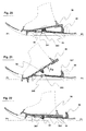
- FIGS. 9 and 10 show another embodiment in which the racket does not have a central platform so that the lower face of the entire portion of the fastening plate 18 located behind the transverse axis of pivoting 20 comes into direct contact with the layer of snow when said fixing plate is folded down.
- the angular deflection downwardly of the fixing plate 18, advantageously limited by stops not shown, is calculated to be sufficient to allow the rear of the plate of the fastener 18 to pass below the passing plane P1 by the lower longitudinal edges of the sieve so that the heel of the shoe is lower than the front of the shoe which is advantageous downhill.
- the plate of the fastener 18 furthermore has on its rear part crampons 19 which are no longer protruding under the plane P1 as soon as the rear of said fixing plate 18 is raised and this to limit the effects of drag.
- FIGS 11 to 14 show another embodiment in which the central platform 21 is hinged relative to the frame of the sieve by a transverse axis 22 disposed near its rear end while a second transverse axis 23 disposed in the vicinity of the front end of said central platform 21 serves as a pivot to the fixing plate 24 which thus performs a relative pivoting movement relative to the sieve of the racket around the two transverse axes 22 and 23.
- the central platform comprises high and low stops limiting angular movement upward and downward and return means, not shown ensuring its automatic return to the high position when no longer loaded.
- the tilting of the boot is performed firstly by rotation about the rear transverse axis 22 which brings the central platform 21 in abutment in its lower position as shown in FIG. figure 12 .
- Tilt of the foot forward is then effected by rotation of the attachment plate 24 about the front transverse axis 23, as shown in FIG. figure 13 .
- the central platform 21 is returned to its upper position by the biasing means, and the front of the plate of the fastener 24 is found above the plane P1 passing through the lower longitudinal edges of the sieve.
- the figure 15 shows another embodiment in which the central platform 25, connected to the frame of the sieve by a transverse axis 27 disposed in its front portion, extends forwardly by a portion cantilevered at the front end of which is disposed a second transverse axis of pivoting 28 connecting said central platform to the plate of the attachment 26.
- the underside of the central platform 25 advantageously comprises crampons arranged on the one hand at its front end, and secondly at its rear end.
- the hold-up device is mounted on the upper face of the rear part of said central platform 25.
- the Figures 17 to 19 show a variant of the embodiment presented on the Figures 1 to 7 .
- the central platform 30 of the racket has in its rear part an opening 300 allowing the passage through the sieve of the cleat clamps 310 mounted under the lower face of the rear end of the plate of the fastener 31.
- these spikes 310 come into prominence under the plane P1 passing through the lower longitudinal edges of the sieve.
- a climb-and-hold wedge device 32 disposed on the rear part of the central platform 30, comprises an element 320 that can slide axially in the direction of the racket to occupy either a retracted position towards the rear ( figure 17 ) an advanced position ( Figures 18 and 19 ).
- the sliding element 320 In the disengaged position, the sliding element 320 is outside the area swept by the plate of the fastener 31, which can therefore move freely over its entire angular deflection.
- the sliding member 320 occupies the position engaged in blocking above the upper face of the plate of the attachment 30, which is kept pressed against the upper face of the central platform 30, and the studs 310 being prominent under the plane P1.
- the crampons 310 are no longer prominent when the plate is raised during the advancement of the foot, which greatly contributes to reducing the effect of drag.
- the height of the climb-and-hold device may be smaller than the prior systems. This results in a reduction in device volume, a reduction in weight, and easy integration directly into the sieve.
- FIGS. 20 to 22 show another embodiment of a snowshoe according to the invention comprising a device accumulating the energy during the downward folding of the fixing plate, and the restituant, with losses, in the form of a force pushing up Fp tending to push up the rear of said fixing plate 360.
- the element accumulating and restoring this energy consists here of a progressive conical abutment 33 of elastically deformable rubber positioned between the axis of pivoting of the fixing plate 36 and the rear end of said fixing plate.
- This stop 33 is fixed under the lower face of the plate 36 of the binding and the device also comprises a support plate 350 sliding in the axial direction of the racket in solidarity with a raising block 35 acting as a wedge climb.
- FIGs 20 and 21 show the operation of said device when the shim 35 and the bearing plate 350 associated with it occupy the advanced position, thus engaged.
- the plate of the fastener 36 first folds freely without encountering an opposing force until the conical abutment comes into contact with the bearing plate 350. This results in a pivoting movement towards the bottom of the fixing plate 36 which results in the progressive crushing of the stop 33 against an increasing reaction force stored in said stop 33.
- the pivoting movement towards the bottom of the shoe stops when the lower rear face of the plate of the fastener 36 bears on the booster pad 35 ( figure 20 ).
- the progressive abutment 33 releases the energy it contained by its compression by generating a thrust force Fp which facilitates the forward tilting of the attachment plate 33 and the boot that it supports, thereby facilitating the ascent of the climb in progress.
- the figure 22 shows the configuration of the racket when the device accumulating the energy is deactivated.
- the booster 35 acting as a climbing wedge, and the support plate 350 associated therewith occupy their retracted position.
- the support plate 350 is therefore no longer positioned on the path traveled by the conical abutment 33 during the pivoting of the fixing plate 36. Therefore, neither the abutment 33 nor the fixing plate 36 can meet any more support during their pivoting down.
- the plate of the fastener 36 can travel freely all of its angular travel until it comes into contact with the upper face of the sieve while the conical abutment is housed in a cavity 340 formed in said sieve.
- the cavity in which the conical abutment is housed can be closed downwards or, conversely, open downwards as shown in FIG. figure 22 . It can then advantageously comprise a wall disposed under the underside of the screen and positioned in front of the opening 340, so inclined forwardly. It serves as a snow deflector by preventing the upwelling through the opening 340 when the racket advances by sliding on the ground.
- the Figures 23 to 25 show in cross section different embodiments of a racket according to the invention, the sieve can tilt laterally P2 and P3 on either side of a neutral horizontal position along PI relative to the assembly consisting of the central platform of the sieve and the plate of the fastener.
- the figure 23 shows a first embodiment in which the frame of the sieve comprises two lateral elements 41 and 42 joined together by a transverse beam 8, said frame being connected to the central platform of the sieve 38 supporting the fixing plate 37 by a flexible joint constituted a deformable element X between the branches which are interposed two blocks 50, 51 made of an elastically flexible deformable material such as rubber or a synthetic elastomer.
- the two blocks 50, 51 of triangular shape have sufficient elastic memory to ensure the automatic return of the sieve frame in the neutral position as soon as the racket is no longer supported on a sloping ground.
- the figure 24 shows a second embodiment in which the pivoting in the lateral direction of the frame of the sieve relative to the central platform of the sieve 52 is effected by pivoting about an axis 53 arranged longitudinally substantially parallel to the longitudinal vertical plane Pvl of the racket .
- Springs 54, 55 disposed on either side of said pivot axis 53 ensure the automatic return of the sieve frame in the neutral position as soon as the racket is no longer supported on a sloping ground.
- the figure 25 shows a third embodiment in which the sieve frame is connected to the central platform of the sieve by at least two links allowing a limited lateral tilting of said central platform on either side of its substantially horizontal neutral position.
- the lateral displacement of the sieve frame relative to the central platform of the sieve 56 is effected by pivoting rods 57,58 each having a first end connected by an axis to a longitudinal arm of the frame, while the second end is connected by another axis to said central platform 46.
- the central platform of the sieve is connected to the frame of the sieve by at least one universal joint or ball joint allowing on the one hand a limited lateral tilting of said central platform on either side of his position substantially horizontal neutral and secondly a tilting in the limited longitudinal direction of said central platform relative to said screen sieve frame.
Abstract
Description
L' invention concerne une raquette à neige comportant :
- un tamis ayant une surface portante composée d'une partie avant recourbée vers le haut en guise de spatule se prolongeant vers l'arrière par un cadre périphérique pouvant être fermé à l'arrière ou ouvert en forme de U,
- une plaque de fixation montée pivotante par rapport au cadre du tamis, et ayant des moyens permettant l'arrimage d'une chaussure.
- a sieve having a bearing surface composed of a front portion curved upwards as a spatula extending rearwardly by a rearward-open or U-shaped peripheral frame,
- a fixing plate pivotally mounted relative to the frame of the screen, and having means for securing a shoe.
Avec les raquettes à neige de l'art antérieur du type décrit dans le document
A chaque réception d'appui sur le sol la face inférieure de la plaque de fixation vient reposer directement et brutalement sur la face supérieure du tamis. Le déroulement du pied vers l'avant exige ensuite un effort important au niveau du mollet en raison du positionnement relativement avancé de l'axe d'articulation de la fixation . Il n'est cependant pas possible de décaler vers l'arrière cet axe de pivotement car l'avant pied viendrait trop rapidement en contact avec le sol et il serait encore davantage proéminent sous la face d'appui du tamis lors du basculement de la chaussure à travers la fenêtre du tamis.At each reception of support on the ground the lower face of the fixing plate comes to rest directly and brutally on the upper face of the sieve. The course of the foot forward then requires a significant effort in the calf because of the relatively advanced positioning of the axis of articulation of the binding. However, it is not possible to shift this pivot axis backward because the forefoot would come too quickly in contact with the ground and it would be even more prominent under the support face of the sieve during the tilting of the shoe through the sieve window.
L'invention vise à remédier à ces différents inconvénients en proposant une raquette à neige permettant un déroulement naturel , progressif et amorti du pied lors de la marche, et diminuant la résistance à l'avancement pour limiter l'effet de traîne.The invention aims to remedy these drawbacks by proposing a snowshoe allowing a natural, progressive and cushioned foot during walking, and decreasing the resistance to travel to limit the effect of drag.
Un autre objet est de proposer une raquette permettant une marche naturelle et sans fatigue en dévers sans avoir à incliner transversalement la cheville.Another object is to provide a racket for natural walking without fatigue in cant without having to tilt the ankle transversely.
La raquette selon l'invention est caractérisée en ce que la plaque de fixation pivotante est articulée sur le cadre du tamis autour d'un premier axe transversal avant en liaison par une biellette intermédiaire de transmission avec un deuxième axe transversal placé à l'arrière dudit premier axe de manière à augmenter le débattement angulaire de la plaque de fixation suite à un mouvement de pivotement combiné autour desdits premier et deuxième axes.The racket according to the invention is characterized in that the pivoting fastening plate is articulated on the frame of the sieve around a first transverse axis before connected by an intermediate transmission rod with a second transverse axis placed at the rear of said first axis so as to increase the angular deflection of the fixing plate due to a combined pivotal movement about said first and second axes.
Selon un mode de réalisation, les deux éléments latéraux longitudinaux, ou bras latéraux longitudinaux, qui constituent les côtés du cadre périphérique se rejoignent entre eux au niveau de l'extrémité arrière de la raquette pour constituer la boucle arrière du cadre qui est alors un cadre périphérique fermé.According to one embodiment, the two longitudinal side members, or longitudinal side arms, which constitute the sides of the peripheral frame join together at the rear end of the racket to form the rear loop of the frame which is then a frame closed device.
Selon un autre mode de réalisation, les deux éléments latéraux longitudinaux, ou bras latéraux longitudinaux, qui constituent les côtés du tamis ne se rejoignent pas entre eux au niveau de l'extrémité arrière de la raquette et le cadre périphérique du tamis est alors ouvert en forme générale de U lorsqu'il est observé en vue de dessus.According to another embodiment, the two longitudinal side members, or longitudinal side arms, which constitute the sides of the sieve do not meet with each other at the rear end of the racket and the peripheral frame of the sieve is then opened in general shape of U when viewed in top view.
La plate-forme centrale du tamis, dont la largeur est inférieure à la largeur du tamis , s'étend dans le sens longitudinal de la raquette à partir de l'extrémité arrière de la fenêtre au travers de laquelle bascule l'avant pied lors de la marche , jusqu'à l'extrémité arrière du tamis lorsque le cadre périphérique est du type ouvert ou jusqu'à proximité de la boucle arrière du cadre périphérique lorsque ce dernier est du type fermé.The central platform of the sieve, whose width is less than the width of the sieve, extends in the longitudinal direction of the racket from the rear end of the window through which the forefoot pivots when the step, to the rear end of the sieve when the peripheral frame is of the open type or close to the rear loop of the peripheral frame when the latter is of the closed type.
La face inférieure de la plateforme centrale comporte avantageusement des éléments proéminents en guise de crampons dont les pointes de certains au moins sont proéminentes par rapport aux bords inférieurs du tamis , le plan passant par les pointes desdits crampons, constituant le plan d'appui de la raquette sur sol dur, se situe donc à une niveau inférieur à celui qu'occupe le plan général passant par les bords longitudinaux inférieurs du tamis que nous considérerons comme étant le plan d'appui du tamis sur neige profonde.The lower face of the central platform advantageously comprises prominent elements as spikes, the tips of which at least some are protruding from the lower edges of the sieve, the plane passing through the tips of said crampons, constituting the support plane of the racket on hard ground, is therefore at a level lower than that occupied by the general plane passing through the edges lower longitudinal sieve which we will consider as the support plane of the sieve on deep snow.
La plateforme centrale du tamis peut être solidaire du cadre périphérique du tamis avec lequel elle constitue un ensemble rigide. Selon une variante, la plateforme centrale et le cadre du tamis constituent deux sous-ensembles distincts reliés entre eux par des moyens élastiquement déformables, et/ou par des moyens mécaniques rigides ou présentant au contraire un ou plusieurs degrés de liberté tels que notamment des axes, des rotules , des cardans ou des biellettes .The central platform of the sieve may be integral with the peripheral frame of the sieve with which it forms a rigid assembly. According to one variant, the central platform and the frame of the sieve constitute two distinct subassemblies interconnected by elastically deformable means, and / or by rigid mechanical means or, on the contrary, having one or more degrees of freedom, such as, in particular, axes , ball joints, gimbals or connecting rods.
Selon une autre variante, le tamis de la raquette ne comporte pas de plateforme centrale et c'est alors la face inférieure de la plaque de la fixation qui est en contact direct avec la neige lorsque ladite plaque occupe sa position rabattue vers le bas. La plaque de fixation est alors reliée au cadre du tamis par l'axe transversal arrière de la biellette de liaison..According to another variant, the sieve of the racket does not have a central platform and it is then the underside of the plate of the binding which is in direct contact with the snow when said plate is in its folded position downwards. The fixing plate is then connected to the frame of the sieve by the transverse rear axis of the connecting rod.
Selon une autre caractéristique d'un mode préférentiel de réalisation, le cadre du tamis peut s'incliner latéralement selon un angle limité par rapport à la plate-forme centrale ou seulement par rapport à l'axe arrière de pivotement de la biellette intermédiaire , lorsque le tamis ne comporte pas de plate-forme centrale . Pour ce faire ledit cadre du tamis est relié à la plate-forme centrale ou à l'axe de pivotement arrière de la biellette intermédiaire par des moyens souples élastiquement déformables et/ou par des moyens mécaniques comportant des articulations tels que des biellettes , des rotules ou des cardans ou tels encore q'un axe s'étendant dans le sens longitudinal du tamis .According to another characteristic of a preferred embodiment, the frame of the sieve can tilt laterally at a limited angle relative to the central platform or only relative to the rear pivot axis of the intermediate link, when the screen does not have a central platform. To do this, said frame of the screen is connected to the central platform or to the rear pivoting axis of the intermediate link by elastically deformable flexible means and / or by mechanical means comprising articulations such as links, ball joints or gimbals or such that an axis extending in the longitudinal direction of the sieve.
Ce basculement latéral du cadre du tamis peut s'effectuer de part et d'autre d'une position neutre sensiblement horizontale donc sensiblement parallèle à la plateforme centrale du tamis, dans laquelle il se repositionne par rapport à ladite plateforme centrale lorsque la raquette prend appui sur un sol enneigé horizontal .This lateral tilting of the sieve frame can be carried out on both sides of a substantially horizontal neutral position, therefore substantially parallel to the central platform of the sieve, in which it is repositioned with respect to said central platform when the racket is supported. on a snowy ground horizontal.
Le retour du cadre du tamis vers sa position neutre peut aussi être avantageusement assuré automatiquement par des moyens élastiques de rappel à l'encontre desquels ledit cadre du tamis s'incline latéralement par rapport à la plateforme centrale du tamis lorsqu'il y est contraint par son appui sur un terrain incliné. Les moyens élastiques ramènent le cadre du tamis dans sa position neutre par rapport à la plateforme centrale aussitôt que la raquette n'est plus en contact avec le sol.The return of the frame of the sieve to its neutral position can also be advantageously ensured automatically by elastic return means against which said frame of the sieve tilts laterally with respect to the central platform of the sieve when it is constrained by its support on inclined ground. Elastic means return the sieve frame to its neutral position relative to the central platform as soon as the racket is no longer in contact with the ground.
Les moyens de rappel assurent le retour en position haute de la biellete intermédiaire ainsi que la limitation vers le haut, par une butée ou par tout autre moyen équivalent, du débattement angulaire de ladite biellette autour de l'axe transversal qui la relie à la plateforme centrale ou directement au cadre du tamis . En effet lorsqu'un pas est fini et que le raquettiste soulève son pied pour avancer la raquette en effectuant le pas suivant cette force de rappel associée à la limitation du débattement angulaire, remonte immédiatement la partie avant de la fixation, et donc de la chaussure, suffisamment vers le haut par rapport au tamis pour que celle-ci ne soit plus être en proéminence sous la face inférieure de la spatule. L'effet de traînée est ainsi limité.The return means ensure the return to the upper position of the intermediate link and the limitation upwards, by a stop or by any other equivalent means, of the angular displacement of said link around the transverse axis which connects it to the platform centrally or directly to the frame of the sieve. Indeed when a step is finished and the racket raises its foot to advance the racket by taking the step following the restoring force associated with the limitation of the angular movement, immediately back the front part of the binding, and therefore the shoe , sufficiently upwards relative to the sieve so that it is no longer protruding under the underside of the spatula. The drag effect is thus limited.
Lorsque la raquette est posée sur le sol sans être chargée, le premier axe transversal avant occupe une position plus haute , donc plus éloignée du plan d'appui de la raquette sur la neige que le deuxième axe de pivotement arrière. En fin d'appui du pas , l'axe transversal avant s'est déplacé suffisamment vers le bas pour se retrouver à une position inférieure à celle de l'axe transversal arrière.When the racket is placed on the ground without being loaded, the first transverse axis before occupies a higher position, therefore further from the support plane of the racket on the snow than the second rear pivot axis. At the end of step support, the front transverse axis has moved sufficiently downwards to be at a lower position than the rear transverse axis.
Selon une autre caractétistique importante , bien que la fixation réalise un mouvement de pivotement relatif par rapport au cadre du tamis autour de deux axes transversaux seul un seul axe transversal, en l'occurrence l'axe transversal arrière, est solidarisé directement au cadre du tamis , l'axe transversal avant étant mobile dans le plan vertical et complètement désolidarisée dudit cadre du tamis avec lequel il n'est pas en contact.According to another important feature, although the fastener performs a relative pivoting movement relative to the frame of the sieve around two transverse axes only a single transverse axis, in this case the transverse rear axis, is secured directly to the frame of the sieve , the transverse axis before being movable in the vertical plane and completely disengaged from said frame of the sieve with which it is not in contact.
Selon une caractéristique complémentaire importante , lorsque ces crampons sont en position escamotée leur partie supérieure ou la partie supérieure des supports dont ils sont solidaires se retrouve en position proéminente au dessus de la face supérieure du tamis et ils constituent des zones d'appui sur lesquelles la face inférieure de la plaque pivotante de fixation vient prendre appui lors de son mouvement qui l'amène en position rabattue vers le bas contre la face supérieure du tamis .According to an important additional characteristic, when these crampons are in the retracted position their upper part or the upper part of the supports which they are integral is found in a protruding position above the upper face of the sieve and they constitute support zones on which the underside of the pivoting plate attachment is supported during its movement which brings it in the folded down position against the upper face of the sieve.
Les moyens de rappel en position escamotée desdits crampons constituent ainsi des amortisseurs d'impact pour la plaque pivotante de la fixation qui se retrouve progressivement freinée en douceur dans sa phase finale de rotation vers le bas au fur et à mesure que la force d'appui qu'elle exerce à l'encontre des moyens de rappel en escamotage des crampons se traduit par l'amenée en position proéminente correspondante des crampons sous le tamis et de leur pénétration dans la neige.The retraction means in the retracted position of said crampons thus constitute impact dampers for the pivoting plate of the binding, which is progressively braked gently in its final phase of downward rotation as the bearing force increases. that it exercises against the means of recall in retraction of the crampons results in the bringing to the corresponding prominent position of the crampons under the sieve and their penetration into the snow.
Dans sa partie arrière la raquette comporte une cale de montée-bloqueur, permettant, lorsqu'il est en position active, soit d'immobiliser en rotation la plaque de fixation en la maintenant plaquée contre la plateforme centrale soit au contraire de constituer une butée basse sur laquelle vient reposer l'extrémité arrière de la plaque de fixation pour limiter le débattement angulaire vers le bas de la plaque de fixation en rendant ainsi plus aisée la marche dans les fortes montées.In its rear part, the racket comprises a blocking-up wedge, allowing, when it is in the active position, either to immobilize in rotation the fixing plate while keeping it pressed against the central platform or, on the contrary, to constitute a low stop on which rests the rear end of the fixing plate to limit the angular movement downwardly of the fixing plate, thus making it easier to walk in the strong climbs.
Selon une autre caractéristique, la raquette comporte un dispositif accumulateur d'énergie lors du rabattement vers le bas de la plaque de fixation et la restituant, aux pertes près , sous la forme d'une force ou d'un couple tendant à repousser vers le haut l'arrière de ladite plaque de fixation lors de sa rotation vers le haut .According to another characteristic, the racket comprises an energy accumulator device during the downward folding of the fixing plate and restoring it, with the losses, in the form of a force or a torque tending to push towards the high back of said fixing plate during its upward rotation.
Selon une autre caractéristique, le tamis de la raquette est asymétrique , la raquette gauche restant cependant symétrique de la raquette droite et le bord longitudinal du tamis situé du côté extérieur du pied est curviligne convexe dans le sens longitudinal de la raquette tandis que, du coté du tamis situé du coté intérieur du pied , une partie au moins du bord longitudinal de la partie du tamis s'étendant vers l'arrière à partir de la base de la spatule est curviligne concave dans le sens longitudinal de la raquette.According to another feature, the sieve of the racket is asymmetrical, the left racket however remaining symmetrical with the right racket and the longitudinal edge of the sieve located on the outside of the foot is curvilinear convex in the longitudinal direction of the racket while, on the side sieve located on the inner side of the foot, at least a portion of the longitudinal edge of the portion of the sieve extending rearwardly from the base of the spatula is curvilinear concave in the longitudinal direction of the racket.
D'autres avantages et caractéristiques ressortiront plus clairement de la description qui va suivre de modes particuliers de réalisation de l'invention donnés à titre d'exemples non limitatifs et représentés aux dessins annexés, dans lesquels :
- les
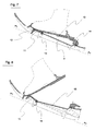
figures 1 à 7 sont des coupes longitudinales verticales montrant les différentes positions caractéristiques du déroulement complet d'un pas avec une raquette à neige selon l'invention réalisée selon un mode de réalisation préférentiel dans lequel la fixation est reliée à la plate-forme centrale du tamis par l'intermédiaire d'une biellette de liaison , - la
figure 8 est une coupe longitudinale verticale montrant un second mode de réalisation de la raquette selon l'invention dont la plateforme centrale est montée pivotante autour de l'axe transversal arrière de la biellette de liaison, - les
figures 9 à 10 sont des coupes longitudinales verticales montrant un troisième mode de réalisation d'une raquette selon l'invention dont la fixation est reliée au cadre du tamis par une biellette de liaison mais dont le tamis ne comporte pas de plate-forme centrale , - les
figures 11 à 14 sont des coupes longitudinales verticales montrant un troisième mode de réalisation d'une raquette selon l'invention dont la plate-forme centrale est reliée au cadre du tamis, fermé à l'arrière, par un axe transversal de pivotement , - la
figure 15 est une coupe longitudinale verticale montrant un quatrième mode de réalisation d'une raquette selon l'invention dont la plate-forme centrale est reliée au cadre du tamis, ouvert à l'arrière, par un axe transversal de pivotement , - la
figure 16 est une représentation en vue de dessus de la raquette à neige représentée sur lesvues 1 à 8 . Pour faciliter la compréhension du dessin , la fixation n'a pas été représentée sur cette vue , - les
figures 17 à 19 sont des coupes longitudinales verticales montrant un mode de réalisation d'une raquette selon l'invention comportant un dispositif cale de montée-bloqueur particulier, - les
figures 20 à 22 sont des coupes longitudinales verticales montrant un mode de réalisation d'une raquette selon l'invention comportant un dispositif particulier d'absorption et de restitution d'énergie , - les
figures 23 à 25 sont des coupes transversales verticales montrant différents modes de réalisation d'une raquette à neige selon l'invention dont le cadre du tamis peut s'incliner dans le sens transversal par rapport à la plate-forme centrale du tamis.
- the
Figures 1 to 7 are vertical longitudinal sections showing the different characteristic positions of the complete unfolding of a step with a snowshoe according to the invention carried out according to a preferred embodiment in which the binding is connected to the central platform of the sieve by the intermediate of a connecting rod, - the
figure 8 is a vertical longitudinal section showing a second embodiment of the racket according to the invention, the central platform is pivotally mounted around the rear transverse axis of the connecting rod, - the
Figures 9 to 10 are vertical longitudinal sections showing a third embodiment of a racket according to the invention, the attachment of which is connected to the frame of the sieve by a link rod but whose sieve does not have a central platform, - the
Figures 11 to 14 are vertical longitudinal sections showing a third embodiment of a racket according to the invention, the central platform of which is connected to the frame of the sieve, closed at the rear, by a transverse axis of pivoting, - the
figure 15 is a vertical longitudinal section showing a fourth embodiment of a racket according to the invention, the central platform of which is connected to the frame of the sieve, open at the rear, by a transverse axis of pivoting, - the
figure 16 is a top view of the snowshoe shown in views 1-8. To facilitate the understanding of the drawing, the fixation has not been represented on this view, - the
Figures 17 to 19 are vertical longitudinal sections showing an embodiment of a racket according to the invention comprising a particular wedge-up blocker device, - the
Figures 20 to 22 are vertical longitudinal sections showing an embodiment of a racket according to the invention comprising a particular device for absorbing and restoring energy, - the
Figures 23 to 25 are vertical cross sections showing different embodiments of a snowshoe according to the invention, the frame of the sieve can tilt in the transverse direction relative to the central platform of the sieve.
Préalablement aux explications suivantes, il est stipulé que les références d'horizontalité et de verticalité mentionnées dans le présent document s'entendent par rapport à une raquette reposant par sa face d'appui sur un sol horizontal et que, par ailleurs , le plan désigné sous le terme de plan longitudinal vertical moyen ou de plan vertical moyen, est le plan vertical qui passe par l'axe moyen tibia-péroné, ledit plan étant par ailleurs disposé sensiblement parallèlement à l'axe de la marche le long duquel se déplace le raquettiste . Il est également précisé que les notions d'extérieur et d'intérieur se définissent par rapport audit plan vertical longitudinal moyen , le côté intérieur s'étendant latéralement à partir dudit plan en direction de l'autre raquette, tandis que le côté extérieur s'étend latéralement à partir de l'autre face du plan moyen et dans le sens opposé au précédent . Quant à la notion de position neutre de la plate-forme par rapport au tamis de la raquette celle-ci correspond à la position horizontale qu'occupe ladite plate-forme lorsque la raquette repose sur un sol horizontal .Prior to the following explanations, it is stipulated that the references of horizontality and verticality mentioned in this document are in relation to a racket resting by its bearing surface on a horizontal ground and that, moreover, the designated plan under the term mean vertical longitudinal plane or plane mean vertical, is the vertical plane passing through the middle tibia-fibula axis, said plane being moreover disposed substantially parallel to the axis of the walk along which the snowshoer moves. It is also specified that the concepts of exterior and interior are defined with respect to said mean longitudinal vertical plane, the inner side extending laterally from said plane towards the other racket, while the outer side s' extends laterally from the other side of the middle plane and in the opposite direction to the previous one. As for the notion of neutral position of the platform with respect to the sieve of the racket, it corresponds to the horizontal position occupied by said platform when the racket rests on a horizontal ground.
Sur les
La plate-forme centrale 3 s'étend du voisinage de l'extrémité arrière de la fenêtre 70 aménagée dans la spatule 7 , au travers de laquelle bascule l'avant pied lors de la marche , jusqu'à l'extrémité arrière du tamis 2.The
La fixation de la raquette est constituée par une plaque pivotante 10 comportant des moyens d'arrimage de la chaussure. La plaque pivotante 10 est reliée à la plateforme centrale 3 par une biellette de liaison 11 dont l'extrémité avant est articulée par rapport à ladite plaque de fixation 10 par un axe transversal avant 12 tandis que son extrémité arrière est articulée par rapport à la plateforme centrale 3 ou au cadre du tamis par un axe transversal arrière 13 . La plaque de fixation pivote donc par rapport au cadre du tamis autour d'au moins un axe transversal avant et d'au moins un axe transversal arrière .
La biellette de liaison 11 comporte sous sa face inférieure avant des éléments proéminents 110 destinées à assurer un bon ancrage dans la neige en montée ; ces éléments proéminents 110 ont ici la forme de dents orientées selon une direction générale s'étendant de l'arrière vers le haut à l'avant vers le bas .The fixing of the racket is constituted by a pivoting
The connecting
Un dispositif rotatif 14 est monté sur la face supérieure de la partie arrière de la plate-forme centrale 3 . Ce dispositif, monté rotatif autour d'un axe vertical, peut occuper trois positions caractéristiques :
- une position inactive , désengagée, tel que le montrent les
figures 1 à 5 , dans laquelle il laisse à laplaque 10 de la fixation la possibilité de se déplacer sur la totalité de son débattement angulaire . - une première position active , engagée, en guise de bloqueur , représentée sur la
figure 6 , dans laquelle , après une rotation de 180° par rapport à la position qu'il occupait sur lesfigures 1 à 5 la partie antérieure 140 de sa base vient immobiliser en rotationla plaque 10 de la fixation qui reste plaquée contre la plateforme centrale 3 de telle sorte que le tamis 2 accompagne alors tous les mouvements de la chaussure pour permettre le franchissement de passages difficiles ou très escarpés. - Une seconde position active, engagée, en guise de cale de montée, représentée sur la
figure 7 , dans laquelle il constitue une butée inférieure pour l'extrémité arrière de laplaque 10 de la fixation dont il limite ainsi le débattement angulaire vers le bas pour un plus grand confort dans les montées .
- an inactive, disengaged position, as shown by
Figures 1 to 5 , in which it leaves theplate 10 of the fixation the possibility of moving on all of its angular deflection. - a first active position, engaged, as a blocker, represented on the
figure 6 , in which, after a rotation of 180 ° with respect to the position it occupied on theFigures 1 to 5 theanterior portion 140 of its base immobilizes in rotation theplate 10 of the binding which remains pressed against thecentral platform 3 so that the sieve 2 then accompanies all movements of the shoe to allow crossing difficult or very steep passages . - A second active position, engaged, as a climbing wedge, represented on the
figure 7 , in which it constitutes a lower abutment for the rear end of theplate 10 of the binding which thus limits the angular deflection downwards for greater comfort in climbs.
Comme le montrent plus particulièrement les
permet , grâce à une distance d réduite, de diminuer dans des proportions conséquentes l'effort, selon la force F, que doivent fournir les muscles du mollet pour soulever le talon de la chaussure lors du déroulement du pied.
La première phase du basculement du pied selon l'angle (alpha) se fait donc par pivotement de la plaque de fixation 10 autour de l'axe transversal arrière 13 à l'encontre de la force de rappel développée par des moyens de rappel, non visibles sur ces dessins, consistant en un ressort de torsion disposé concentriquement autour de l'axe transversal arrière 13 et tendant à rappeler automatiquement la biellette de liaison 11 dans sa position haute telle que représentée sur les
Lorsque la biellette de liaison 11 a atteint sa position basse et que les griffes avant 110 qui l'équipent entrent en contact avec le sol la plaque de la fixation 10 continue son mouvement de basculement vers l'avant en pivotant autour de l'axe transversal avant 12 pour effectuer le débattement angulaire (Béta).As shown more particularly by
allows, thanks to a reduced distance d, to decrease in substantial proportions the effort, according to the force F, that must provide the calf muscles to lift the heel of the shoe during the unwinding of the foot.
The first phase of tilting of the foot according to the angle ( alpha ) is therefore by pivoting the fixing
When the connecting
A la fin de la phase de déroulement du pied, la plaque 10 de la fixation a donc effectué une rotation angulaire de valeur totale (Gamma) par rapport à la plate-forme centrale 3 du tamis.
Tel que le montre la
On note également sur ces différentes figures que le plan P0 passant par les pointes des crampons fixés sous le tamis occupe une position inférieure à celle du plan P1 passant par les bords longitudinaux inférieurs dudit tamis .At the end of the unwinding phase of the foot, the
As shown in
It is also noted in these various figures that the plane P0 passing through the points of the crampons fixed under the sieve occupies a position lower than that of the plane P1 passing through the lower longitudinal edges of said sieve.
La
Des moyens de rappel, (non représentés) et constitués par exemple d'un ressort de torsion disposé autour de l'axe transversal 16, assurent avantageusement le rappel automatique de la plateforme dans sa position haute aussitôt qu'elle n'est plus chargée et ils offrent par ailleurs l'avantage de freiner en l'amortissant le rabattement par pivotement vers le bas autour de l'axe 16 de l'ensemble plaque de fixation et plateforme centrale lorsque la raquette entre en contact avec le sol.Returning means, (not shown) and consisting for example of a torsion spring disposed about the
Sur cette
Les
Comme le montre la
Les
La plateforme centrale comporte des butées haute et basse limitant sont débattement angulaire vers le haut et vers le bas ainsi que des moyens de rappel , non représentés assurant son retour automatique en position haute lorsqu'elle n'est plus chargée.The central platform comprises high and low stops limiting angular movement upward and downward and return means, not shown ensuring its automatic return to the high position when no longer loaded.
Comme le montrent la
Lors du déroulement du pas , le basculement de la chaussure s'effectue tout d'abord par rotation autour de l'axe transversal arrière 22 qui amène la plateforme centrale 21 en butée dans sa position basse tel que représenté sur la
Le basculement du pied vers l'avant s'effectue ensuite par rotation de la plaque de fixation 24 autour de l'axe transversal avant 23 , comme représenté sur la
Tilt of the foot forward is then effected by rotation of the
Sur la
La
La face inférieure de la plateforme centrale 25 comporte avantageusement des crampons disposés d'une part au niveau de son extrémité avant, et d'autre part au niveau de son extrémité arrière. Le dispositif cale de montée- bloqueur est monté sur la face supérieure de la partie arrière de ladite plateforme centrale 25 .The underside of the
Les
Un dispositif de cale de montée-bloqueur 32 disposé sur la partie arrière de la plateforme centrale 30, comprend un élément 320 pouvant coulisser axialement dans le sens longitudinal de la raquette pour occuper soit une position reculée vers l'arrière (
Dans la position désengagée , l'élément coulissant 320 se situe à l'extérieur de la zone balayée par la plaque de la fixation 31, qui peut donc se déplacer librement sur la totalité de son débattement angulaire .In the disengaged position, the sliding
Sur la
Sur la
Les crampons 310 ne sont plus en proéminence lorsque la plaque est relevée pendant l'avancement du pied, ce qui contribue grandement à réduire l'effet de traînée. La hauteur du dispositif cale de montée-bloqueur peut être plus réduite que les systèmes antérieurs. Il en découle une réduction de volume du dispositif, une réduction de poids, et une intégration facile directement dans le tamis.The
Les
L'élément accumulant et restituant cette énergie est constitué ici d'une butée conique progressive 33 en caoutchouc élastiquement déformable positionnée entre l'axe de pivotement de la plaque de fixation 36 et l'extrémité arrière de ladite plaque de fixation . Cette butée 33 est fixée sous la face inférieure de la plaque 36 de la fixation et le dispositif comprend par ailleurs une plaque d'appui 350 coulissant dans le sens axial de la raquette de façon solidaire avec une cale de surélévation 35 jouant le rôle de cale de montée .The element accumulating and restoring this energy consists here of a progressive
Les
Lorsque l'utilisateur commence ensuite à soulever son pied pour engager le pas suivant , tel que représenté sur la
La
La cavité dans laquelle vient se loger la butée conique peut être fermée vers le bas ou au contraire ouverte vers le bas tel que représentée sur la
Les
Il faut noter que durant ces inclinaisons, les pointes des crampons solidaires de la plateforme centrale du tamis restent en permanence contenues dans le plan P0 qui reste sensiblement horizontal .It should be noted that during these inclinations, the points of the crampons integral with the central platform of the sieve remain permanently contained in the plane P0 which remains substantially horizontal.
La
La
La
Selon un autre mode de réalisation non représenté, la plate-forme centrale du tamis est reliée au cadre du tamis par au moins un cardan ou une rotule autorisant d'une part un basculement latéral limité de ladite plate forme centrale de part et d'autre de sa position neutre sensiblement horizontale et d'autre part un basculement dans le sens longitudinal limité de ladite plateforme centrale par rapport audit cadre du tamis du tamis.According to another embodiment not shown, the central platform of the sieve is connected to the frame of the sieve by at least one universal joint or ball joint allowing on the one hand a limited lateral tilting of said central platform on either side of his position substantially horizontal neutral and secondly a tilting in the limited longitudinal direction of said central platform relative to said screen sieve frame.
Bien sûr l'invention n'est pas limitée aux seuls modes représentés et décrits à titre d'exemples mais elle comprend aussi leurs combinaisons et leurs équivalents techniques.Of course, the invention is not limited to the only modes shown and described by way of examples, but it also includes their combinations and their technical equivalents.
Claims (8)
Applications Claiming Priority (1)
| Application Number | Priority Date | Filing Date | Title |
|---|---|---|---|
| FR0701323A FR2912928B1 (en) | 2007-02-23 | 2007-02-23 | PERFECTED SNOW SQUIRREL |
Publications (2)
| Publication Number | Publication Date |
|---|---|
| EP1961463A1 true EP1961463A1 (en) | 2008-08-27 |
| EP1961463B1 EP1961463B1 (en) | 2010-11-03 |
Family
ID=38776165
Family Applications (1)
| Application Number | Title | Priority Date | Filing Date |
|---|---|---|---|
| EP08354015A Not-in-force EP1961463B1 (en) | 2007-02-23 | 2008-02-22 | Improved snowshoe |
Country Status (4)
| Country | Link |
|---|---|
| EP (1) | EP1961463B1 (en) |
| AT (1) | ATE486643T1 (en) |
| DE (1) | DE602008003245D1 (en) |
| FR (1) | FR2912928B1 (en) |
Cited By (5)
| Publication number | Priority date | Publication date | Assignee | Title |
|---|---|---|---|---|
| EP2142026A1 (en) * | 2007-04-27 | 2010-01-13 | Easton Technical Products, Inc. | Snowshoe apparatus |
| WO2012140581A1 (en) * | 2011-04-11 | 2012-10-18 | Stefano Maruelli | Locking system for toe - lifting bindings |
| US10159890B2 (en) | 2016-01-23 | 2018-12-25 | Markus Steinke | Heel unit fora touring ski-binding |
| WO2018235002A1 (en) * | 2017-06-22 | 2018-12-27 | Backwards Spolka Z Ograniczona Odpowiedzialnoscia | Binding allowing lifting of the front as well as the heel of the users foot |
| US10188935B2 (en) | 2016-01-23 | 2019-01-29 | Markus Steinko | System for a touring ski-binding comprising a front unit and a heel unit |
Families Citing this family (1)
| Publication number | Priority date | Publication date | Assignee | Title |
|---|---|---|---|---|
| FR3075060B1 (en) | 2017-12-15 | 2022-03-04 | Martin Plastiques Participations | SNOWSHOE |
Citations (3)
| Publication number | Priority date | Publication date | Assignee | Title |
|---|---|---|---|---|
| EP0882478A1 (en) | 1997-06-04 | 1998-12-09 | Salomon S.A. | Snowshoe with a floating foot support member |
| FR2779659A1 (en) * | 1998-06-16 | 1999-12-17 | Christophe Oddoux | Double-articulating device for boot to ski attachment |
| US6898874B2 (en) | 2002-01-04 | 2005-05-31 | K2 Snowshoes, Inc. | Snowshoe with two degrees of rotational freedom |
Family Cites Families (1)
| Publication number | Priority date | Publication date | Assignee | Title |
|---|---|---|---|---|
| FR2768938B1 (en) * | 1997-10-01 | 1999-11-05 | Salomon Sa | SNOWSHOE |
-
2007
- 2007-02-23 FR FR0701323A patent/FR2912928B1/en not_active Expired - Fee Related
-
2008
- 2008-02-22 DE DE602008003245T patent/DE602008003245D1/en active Active
- 2008-02-22 AT AT08354015T patent/ATE486643T1/en active
- 2008-02-22 EP EP08354015A patent/EP1961463B1/en not_active Not-in-force
Patent Citations (3)
| Publication number | Priority date | Publication date | Assignee | Title |
|---|---|---|---|---|
| EP0882478A1 (en) | 1997-06-04 | 1998-12-09 | Salomon S.A. | Snowshoe with a floating foot support member |
| FR2779659A1 (en) * | 1998-06-16 | 1999-12-17 | Christophe Oddoux | Double-articulating device for boot to ski attachment |
| US6898874B2 (en) | 2002-01-04 | 2005-05-31 | K2 Snowshoes, Inc. | Snowshoe with two degrees of rotational freedom |
Cited By (8)
| Publication number | Priority date | Publication date | Assignee | Title |
|---|---|---|---|---|
| EP2142026A1 (en) * | 2007-04-27 | 2010-01-13 | Easton Technical Products, Inc. | Snowshoe apparatus |
| EP2142026A4 (en) * | 2007-04-27 | 2014-08-13 | Easton Technical Products Inc | Snowshoe apparatus |
| WO2012140581A1 (en) * | 2011-04-11 | 2012-10-18 | Stefano Maruelli | Locking system for toe - lifting bindings |
| US10159890B2 (en) | 2016-01-23 | 2018-12-25 | Markus Steinke | Heel unit fora touring ski-binding |
| US10188935B2 (en) | 2016-01-23 | 2019-01-29 | Markus Steinko | System for a touring ski-binding comprising a front unit and a heel unit |
| WO2018235002A1 (en) * | 2017-06-22 | 2018-12-27 | Backwards Spolka Z Ograniczona Odpowiedzialnoscia | Binding allowing lifting of the front as well as the heel of the users foot |
| US20200139220A1 (en) * | 2017-06-22 | 2020-05-07 | Backwards Spólka Z Ograniczona Odpowiedzialnoscia | Binding allowing lifting of the front as well as the heel of the users foot |
| US11697057B2 (en) | 2017-06-22 | 2023-07-11 | Backwards Spółka Z Ograniczoną Odpowiedzialnością | Binding allowing lifting of the front as well as the heel of the users foot |
Also Published As
| Publication number | Publication date |
|---|---|
| FR2912928B1 (en) | 2012-09-07 |
| EP1961463B1 (en) | 2010-11-03 |
| FR2912928A1 (en) | 2008-08-29 |
| ATE486643T1 (en) | 2010-11-15 |
| DE602008003245D1 (en) | 2010-12-16 |
Similar Documents
| Publication | Publication Date | Title |
|---|---|---|
| EP1961463B1 (en) | Improved snowshoe | |
| EP1447019B1 (en) | Shoe sole | |
| EP0026148B1 (en) | Device for allowing movement on snow | |
| EP2082788B1 (en) | Alpine ski with adjustment means | |
| FR2533833A1 (en) | Ski binding with compensation system | |
| FR2642980A1 (en) | Binding device for a cross-country ski and boot intended for such a binding device | |
| EP0653231B1 (en) | Binding element for skis | |
| EP0658360A1 (en) | Intermediate device between a ski and the binding | |
| FR2999091A1 (en) | Brake device for touring ski, has brake which is adapted to change ski to braking position and non-braking position, and is provided with functional element to form adjustable rise wedge, when brake is in non-braking position | |
| FR2768938A1 (en) | Snow shoe | |
| FR2465498A1 (en) | ELEMENT FORMING FRONT OR REAR JAWS FOR SKI FIXING | |
| CA2270296C (en) | Sliding vehicle for snow sports | |
| EP1393783B1 (en) | Fixation on the frontside for a sportarticle | |
| EP1104685B1 (en) | Automatic binding for snowboard | |
| CH660976A5 (en) | SECURITY FIXING FOR SKIING. | |
| CH675080A5 (en) | ||
| FR2929606A1 (en) | TOWER CRANE ARROW WITH FOLDING-FOLDING MECHANISM | |
| CA2582595A1 (en) | Advanced snowshoe | |
| FR2909630A1 (en) | Sliding vehicle for snow sport, has seat including guiding unit arranged between rotating axle and rear end of seat for guarantying co-planarity between general symmetrical plane of vehicle and symmetrical plane of seat | |
| FR2710275A1 (en) | Ski wheelchair device | |
| FR2885867A1 (en) | Braking system for snowmobile-type vehicle, has elastic coupling unit ensuring angular displacement of braking spades and having rubber blocks prestressed between lower corners of square tube and external faces of another square tube | |
| EP0732966B1 (en) | Support plate for a shoe, particularly a ski boot | |
| FR2556228A1 (en) | Roller-skates, whose wheels have a variable inclination with respect to the ground | |
| CH674468A5 (en) | ||
| EP2030658A1 (en) | Climbing bar and ascender device for snow shoe |
Legal Events
| Date | Code | Title | Description |
|---|---|---|---|
| PUAI | Public reference made under article 153(3) epc to a published international application that has entered the european phase |
Free format text: ORIGINAL CODE: 0009012 |
|
| AK | Designated contracting states |
Kind code of ref document: A1 Designated state(s): AT BE BG CH CY CZ DE DK EE ES FI FR GB GR HR HU IE IS IT LI LT LU LV MC MT NL NO PL PT RO SE SI SK TR |
|
| AX | Request for extension of the european patent |
Extension state: AL BA MK RS |
|
| 17P | Request for examination filed |
Effective date: 20090224 |
|
| AKX | Designation fees paid |
Designated state(s): AT CH DE FR IT LI |
|
| 17Q | First examination report despatched |
Effective date: 20090916 |
|
| GRAP | Despatch of communication of intention to grant a patent |
Free format text: ORIGINAL CODE: EPIDOSNIGR1 |
|
| GRAS | Grant fee paid |
Free format text: ORIGINAL CODE: EPIDOSNIGR3 |
|
| GRAA | (expected) grant |
Free format text: ORIGINAL CODE: 0009210 |
|
| AK | Designated contracting states |
Kind code of ref document: B1 Designated state(s): AT CH DE FR IT LI |
|
| REG | Reference to a national code |
Ref country code: CH Ref legal event code: EP |
|
| REF | Corresponds to: |
Ref document number: 602008003245 Country of ref document: DE Date of ref document: 20101216 Kind code of ref document: P |
|
| REG | Reference to a national code |
Ref country code: CH Ref legal event code: NV Representative=s name: CABINET ROLAND NITHARDT CONSEILS EN PROPRIETE INDU |
|
| PLBE | No opposition filed within time limit |
Free format text: ORIGINAL CODE: 0009261 |
|
| STAA | Information on the status of an ep patent application or granted ep patent |
Free format text: STATUS: NO OPPOSITION FILED WITHIN TIME LIMIT |
|
| 26N | No opposition filed |
Effective date: 20110804 |
|
| REG | Reference to a national code |
Ref country code: DE Ref legal event code: R097 Ref document number: 602008003245 Country of ref document: DE Effective date: 20110804 |
|
| REG | Reference to a national code |
Ref country code: CH Ref legal event code: PL |
|
| PG25 | Lapsed in a contracting state [announced via postgrant information from national office to epo] |
Ref country code: LI Free format text: LAPSE BECAUSE OF NON-PAYMENT OF DUE FEES Effective date: 20120229 Ref country code: CH Free format text: LAPSE BECAUSE OF NON-PAYMENT OF DUE FEES Effective date: 20120229 |
|
| REG | Reference to a national code |
Ref country code: FR Ref legal event code: PLFP Year of fee payment: 9 |
|
| REG | Reference to a national code |
Ref country code: FR Ref legal event code: PLFP Year of fee payment: 10 |
|
| PGFP | Annual fee paid to national office [announced via postgrant information from national office to epo] |
Ref country code: DE Payment date: 20170224 Year of fee payment: 10 Ref country code: FR Payment date: 20170222 Year of fee payment: 10 |
|
| PGFP | Annual fee paid to national office [announced via postgrant information from national office to epo] |
Ref country code: AT Payment date: 20170227 Year of fee payment: 10 |
|
| PGFP | Annual fee paid to national office [announced via postgrant information from national office to epo] |
Ref country code: IT Payment date: 20170221 Year of fee payment: 10 |
|
| REG | Reference to a national code |
Ref country code: DE Ref legal event code: R119 Ref document number: 602008003245 Country of ref document: DE |
|
| REG | Reference to a national code |
Ref country code: AT Ref legal event code: MM01 Ref document number: 486643 Country of ref document: AT Kind code of ref document: T Effective date: 20180222 |
|
| PG25 | Lapsed in a contracting state [announced via postgrant information from national office to epo] |
Ref country code: AT Free format text: LAPSE BECAUSE OF NON-PAYMENT OF DUE FEES Effective date: 20180222 |
|
| REG | Reference to a national code |
Ref country code: FR Ref legal event code: ST Effective date: 20181031 |
|
| PG25 | Lapsed in a contracting state [announced via postgrant information from national office to epo] |
Ref country code: DE Free format text: LAPSE BECAUSE OF NON-PAYMENT OF DUE FEES Effective date: 20180901 |
|
| PG25 | Lapsed in a contracting state [announced via postgrant information from national office to epo] |
Ref country code: IT Free format text: LAPSE BECAUSE OF NON-PAYMENT OF DUE FEES Effective date: 20180222 Ref country code: FR Free format text: LAPSE BECAUSE OF NON-PAYMENT OF DUE FEES Effective date: 20180228 |