EP1960246B1 - Chariot de transport deplaçable manuellement - Google Patents
Chariot de transport deplaçable manuellement Download PDFInfo
- Publication number
- EP1960246B1 EP1960246B1 EP06775888A EP06775888A EP1960246B1 EP 1960246 B1 EP1960246 B1 EP 1960246B1 EP 06775888 A EP06775888 A EP 06775888A EP 06775888 A EP06775888 A EP 06775888A EP 1960246 B1 EP1960246 B1 EP 1960246B1
- Authority
- EP
- European Patent Office
- Prior art keywords
- trolley
- platform
- chassis
- wheel
- frame
- Prior art date
- Legal status (The legal status is an assumption and is not a legal conclusion. Google has not performed a legal analysis and makes no representation as to the accuracy of the status listed.)
- Not-in-force
Links
Images


Classifications
-
- B—PERFORMING OPERATIONS; TRANSPORTING
- B62—LAND VEHICLES FOR TRAVELLING OTHERWISE THAN ON RAILS
- B62B—HAND-PROPELLED VEHICLES, e.g. HAND CARTS OR PERAMBULATORS; SLEDGES
- B62B3/00—Hand carts having more than one axis carrying transport wheels; Steering devices therefor; Equipment therefor
- B62B3/14—Hand carts having more than one axis carrying transport wheels; Steering devices therefor; Equipment therefor characterised by provisions for nesting or stacking, e.g. shopping trolleys
- B62B3/1476—Hand carts having more than one axis carrying transport wheels; Steering devices therefor; Equipment therefor characterised by provisions for nesting or stacking, e.g. shopping trolleys the main load support being a platform
-
- B—PERFORMING OPERATIONS; TRANSPORTING
- B62—LAND VEHICLES FOR TRAVELLING OTHERWISE THAN ON RAILS
- B62B—HAND-PROPELLED VEHICLES, e.g. HAND CARTS OR PERAMBULATORS; SLEDGES
- B62B3/00—Hand carts having more than one axis carrying transport wheels; Steering devices therefor; Equipment therefor
- B62B3/14—Hand carts having more than one axis carrying transport wheels; Steering devices therefor; Equipment therefor characterised by provisions for nesting or stacking, e.g. shopping trolleys
- B62B3/18—Hand carts having more than one axis carrying transport wheels; Steering devices therefor; Equipment therefor characterised by provisions for nesting or stacking, e.g. shopping trolleys nestable by means of pivoted supports or support parts, e.g. baskets
-
- B—PERFORMING OPERATIONS; TRANSPORTING
- B62—LAND VEHICLES FOR TRAVELLING OTHERWISE THAN ON RAILS
- B62B—HAND-PROPELLED VEHICLES, e.g. HAND CARTS OR PERAMBULATORS; SLEDGES
- B62B5/00—Accessories or details specially adapted for hand carts
- B62B5/0006—Bumpers; Safety devices
- B62B5/0009—Stops for moving parts, e.g. rubber elements to eliminate stop noise
Definitions
- the invention relates to a hand-movable transport carriage, which can be inserted in a space-saving way in a same trolley, equipped with a front castors and rear casters chassis, the longitudinally two converging arranged frame parts and in the front region of the chassis has a strut connecting the frame parts, with a push-pull means provided on the rear of the chassis and on a platform supported by the chassis for parking larger objects which is wider at the front than the width of the chassis measured at the front, the platform being either one at the rear or about a located in the front region of the chassis, transverse to the sliding direction of the trolley extending horizontal axis is liftably mounted on the chassis and at a distance from the horizontal axis by means of support points the chassis is supported and wherein a near the sliding means arranged, can be provided for receiving smaller items basket specific.
- a dolly shows the US 2,738,201 A ,
- the first disadvantage is that the customer is relatively heavier when buying Objects, for example, in large packages such as sand, cement, humus bags and the like, they must first raise to a favorable height for him to wear, then let them sink back to the low platform. Arrived at the cash register, the process just described can be repeated. The package must be lifted from the loading platform and placed on the conveyor. After the checkout, the package must be hoisted back onto the platform. Arrived at the car, the package must be lifted again from the loading platform in order to finally be able to stow it in the car. It has recognized this disadvantage and developed cash desks, which, starting from the place of the cashier, to the side are open, which is located opposite the conveyor belt.
- the front portion of the chassis is made very stable by the arrangement of the strut between the front castors and the bends, or between the bends themselves. Of the two frame parts remain only short stubs that end at the front castors and carry them. If strong impacts occur on the front castors, these stubs form only very short levers, so that bending in conjunction with the strut the front ends of the two frame parts is excluded. As a result, sufficient tracking stability of the front castors is guaranteed.
- the advantages of the feature c), finally, are that the proposed trolley due to the larger selected wheel diameter of its front castors on uneven ground much easier to push and shuffle than previously known trolley, in which without exception the wheel diameter of the front castors and rear castors with For example, 125 mm is always the same size. Not to be underestimated is that two large castors and two small casters are in the end cheaper than four large steering and driving wheels. The cost of the proposed trolley can be reduced thereby also.
- the invention is primarily a trolley, whose platform can be arranged higher, so that the loading and unloading of the car is facilitated with heavy goods.
- the cashier process at the checkout can be accelerated and the higher order of goods, the billable goods for a cashier with a scanner gun better and thus faster to reach.
- the trolley is easier to move, which benefits the customers of the markets.
- the advantage of the expanded task is that by the proposed arrangement of the front castors and the rear casters in a stacked composite, where the trolleys are indeed stacked as close as possible, remains sufficient space for the front castors so that the wheels of the front castors Pulling out a trolley from the stack assembly can rotate 180 ° without hooking or jamming with the wheels or the wheel housings of the rear drive rollers adjacent trolley.
- the latter is extremely important, because entangled transport car can be solved only with great effort, and often accompanied by damage, from a stack composite same transport car.
- the support points of the platform are located either at each bend of the longitudinal frame parts or closer to the bends than to the supports for the sliding device are arranged. Then namely the chassis of this trolley can be designed in pronounced lightweight construction, without having to fear a deflection of the two frame parts at high loading.
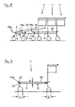
- Fig. 1 shows a hand-movable trolley 1, which is designed in a known manner so that it can be inserted into a same trolley 1 space saving, so can be stacked.
- the trolley 1 has a chassis 4 equipped with front castors 2 and with rear castors 3, which in a known manner converges longitudinally two arranged frame parts 7 has, which are connected in the front region 5 of the chassis 4 by a strut 14.
- a pushing device 16 is provided, which is supported by upwardly directed supports.
- the chassis 4 carries a platform for parking larger objects 18 which is wider in its front area 19 than the width of the chassis 4 measured at the front.
- the platform 18 is located at a rear area 6 of the chassis 4, transverse to the sliding direction of the vehicle Trolley 1 extending horizontal axis 20 liftably mounted on the chassis 4, wherein the usually a rectangular or approximately rectangular plan having platform 18 is disposed between the supports 15. This type of storage is therefore necessary in a known manner, so that the same trolley 1 can be pushed into each other to save space.
- the platform 18 is supported in its position of use by means of support points 21 on the chassis 4 from.
- the strut 14 is arranged at a height which is located between the front drive rollers 2 and the two bends 8.
- the support points 21 are arranged in the example closer to the bends 8 than at the supports 15.
- the wheel diameter A of the front castors 2 is greater than the wheel diameter B of the rear castors 3, see in particular Fig. 2 and Fig. 9 , This applies to all embodiments described here.
- the rear drive rollers 3 may also be designed as castors or as well as known fixed castors, where known, the wheel fork is rigidly arranged.
- the converging frame members 7 a horizontal and a vertical portion 9, 10, on, wherein in each case the two sections 9, 10 are connected by a bend 8. Both frame parts 7 are thus bent downwards.
- a front steering roller 2 is arranged in each case.
- the two supports 15 carry the rear castors 3.
- the above the platform 18 located space is freely accessible.
- the platform 18 can thus be loaded upwards, even beyond the height of the sliding direction 16, with larger objects.
- the two support points 21 for the platform 18 are each at a bend 8 of the two frame parts 7.
- the strut 14 is viewed from the side between the front wheels 2 and the two turns 8 and connects the two frame parts. 7
- the two converging frame parts 7 have a horizontal section 9 and a sloping section 12 leading downwards, each section 9, 12 being connected by a bend 8.
- the support points 21 for the platform 18 are located on a respective horizontal portion 9 of the frame parts 7. All other details correspond to those details, as in Fig. 1 and 2 described.
- the strut 14 connects the two frame parts 7 at a height which is located between the front drive rollers 2 and the bends 8.
- the in Fig. 4 illustrated dolly 1 differs from the previously described dolly 1 in that the two frame parts 7 have a horizontal portion 9 and each horizontal portion 9 is followed by a downwardly leading turn 8. Here therefore lacks the vertical portion 10 or the inclined portion 12.
- the two support points 21 for the platform 18 are located at the bends 8, preferably at the upper end.
- the strut 14 in turn connects the two bends 8 of the two frame parts. 7
- Each section 24 terminates in a bend 8 followed by an inclined section 12, each section 12 carrying at its end a plate 13 for attaching the front castors 2.
- This embodiment is useful for reasons of stability when the platform 18, measured from the floor, is arranged very high. It avoids the need for the two supports 15 unnecessarily long, down stump leading to which the rear drive rollers 3 are attached.
- the two horizontal portions 9 of the two frame parts are connected directly above the plates 13 with the supports 15.
- the remaining short stubs form very short lever arms, which are able to absorb large, occurring during driving impact forces harmless. All other details of the so-designed trolley 1 can be found in the previous description.
- strut 14 close to the front castors in all embodiments.
- This arrangement gives the chassis 4 a high degree of stability.
- weld in each case a plate 13 to the downwardly directed free ends 11 of the frame parts 7, so that a front castor 2 can be screwed to each plate 13.
- the at least two support points 21 may be formed by supports made of plastic, which have elastic properties and thus have a damping effect.
- the two frame parts 7 may be formed by a single component in such a way that the two original frame parts 7 front end in a transverse strut 14, in which case the front drive rollers 2 are secured in a suitable manner to the underside of the strut 14.
- the chassis 4 of a rearwardly inserted trolley 1 is partially received in the frame parts 7 of the chassis 4 of the preceding trolley 1.
- the platform 18 of the rear dolly 1 in turn slides in the telescoping operation at the rear end of the preceding dolly 1 and, the further one carries out the telescoping, more and more raised, see Fig. 5 ,
- the platform 18 of the inserted trolley 1 then assumes a sloping position.
- Fig. 6 shows a hand-movable trolley 1, which is designed in a known manner so that this also in a same trolley 1 space-saving insert, so can be stacked.
- the trolley 1 has a chassis 4 provided with front castors 2 and with rear castors 3, which in a known manner has two longitudinally arranged two converging frame parts 7, which are connected in the front region 5 of the chassis 4 by a strut 14.
- a pushing device 16 is provided, which is supported by upwardly directed supports 15.
- the chassis 4 carries a platform for parking larger objects 18 which is wider in its front area 19, that is to say with its front cross-connection 19a, than the width of the chassis 4 measured at the front.
- the platform 18 is, however, in contrast to those in FIGS FIGS. 1 to 5 described trolley 1 to a located in the front region 5 of the chassis 4, transverse to the sliding direction of the trolley 1 extending horizontal axis 20 liftably mounted on the chassis 4, wherein the usually rectangular plan having platform 18 is disposed between the supports 15.
- This type of storage is therefore necessary in a known manner, so that the same trolley 1 can be pushed into each other to save space.
- the platform 18 is supported in its position of use by means of support points 21, preferably near the supports 15, on the chassis 4 from.
- each of the two frame parts 7 is bent or angled down in the front region 5 of the chassis 4.
- the strut 14 is arranged at a height which is located between the front drive rollers 2 and the two bends 8.
- Fig. 7 shows the in Fig. 6 described dolly 1 viewed from the side.
- the converging frame parts 7 extend forwards.
- Each frame part 7 has a horizontal portion 9 and an obliquely downward portion 12 in the example. It can be seen arranged between the bends 8 and the front castors 2 strut 14, which connects the inclined portions 12 of the frame parts 7.
- a bearing 25 for supporting the platform 18 is arranged, wherein each bearing 25 is designed and arranged such that the horizontal axis 20 about which the platform 18 can be raised, at a distance from the Chassis 4 runs. This can be seen by the distance a formed for each horizontal section 9 and by the distance b formed for each turn 8.
- the location of the bearing 25 located on the horizontal axis 20 is selected in the example so that the platform 18 is divided into a front shorter section 22 and a rear longer section 23. From the drawing, the front cross-connection 19a can be seen, which is designed slightly rising in the example in the sliding direction of the trolley 1.
- Fig. 8 shows three space-saving telescoped dolly 1, as this in the FIGS. 6 and 7 have been described.
- the front cross-connection 19a of the raised platform 18 of the front trolley 1 protrudes forward and does not abut the chassis or the bends 8 of the own trolley 1 at.
- the front cross-connection 19a of the also raised platform 18 of the middle trolley 1 extends at a distance c to the horizontal portion 9 of the frame parts 7 of the foremost transport vehicle 1.
- the cross connection 19a thus does not abut in the raised state of the platform 18 on the chassis 4 of the front trolley. 1 at.
- the platform 18 of the rear trolley 1 finally remains in the position of use.
- the front cross-connection 19a of the platform 18 of this trolley 1 is arranged at a distance from the chassis 4 of the transport trolley ahead and abuts the chassis 4 not.
- the strut 14 in all embodiments according to Fig. 6 to 9 to arrange close to the front wheels 2.
- This arrangement gives the chassis 4 a high degree of stability.
- weld in each of these embodiments to the downwardly directed free ends 11 of the frame parts 7, a plate 13, so that on each plate 13, a front steering roller 2 can be screwed.
- the frame parts 7 may be formed by a single component in such a way that the two original frame parts 7 front end in a transverse strut 14, in which case the front drive rollers 2 are secured in a suitable manner to the underside of the strut 14.
- the invention can be different trolley 1 arise.
- a wheel diameter of the front castors 2 of 160 mm and the rear castors 3 of 125 mm to make the frame parts 7 so that the top of the platform 18 occupies a height H, measured from the floor, of at least 250 mm , please refer Figures 3 and 7 , In all cases, in contrast to the prior art, no more V- or U-shaped support elements required.
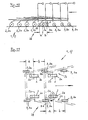
- Fig. 10 shows in side view one of five telescoping trolley 1 formed stack composite 27. It can be seen the front castors 2 and the rear, also designed as castors casters 3 of each dolly 1.
- the wheels 2a of the front castors 2 and the wheels 3a of the rear castors. 3 are in the so-called “Nachlaufwolf", which results in a known manner when the trolley 1 are pushed, as is the case when inserting a trolley 1 in the rear end of the stack assembly 27, see also arrow.
- the tracking position in castors results in a known manner, because the vertical pivot axis of the wheel forks, viewed in side view, are arranged at a distance from the horizontal axles 2b, 3b.
- Measured are measures a and b, whose meaning is explained in more detail below. It can be seen that the wheels 2a of the front castors 2 of the last pushed into the stack assembly 27 transport vehicle 1 between the rear wheels 3 of two adjacent trolley 1 are. This state thus arises at a part 28 of the trolley 1, wherein this part 28 is getting larger, the more trolleys 1 are in a stack composite 27. Based on the drawing, this is easy to imagine.
- Partial and in a top view shows Fig. 11 the front castors 2 of two trolleys 1 and the rear castors 3 three trolley 1, which are located in a stack composite 27.
- the wheels 2 a of the front castors 2 belong to a trolley 1, which forms the rear end of the stack assembly 27 and the stack composite 27 is to be removed.
- the dimension a is smaller than the dimension b.
Landscapes
- Engineering & Computer Science (AREA)
- Chemical & Material Sciences (AREA)
- Combustion & Propulsion (AREA)
- Transportation (AREA)
- Mechanical Engineering (AREA)
- Handcart (AREA)
- Manipulator (AREA)
Claims (11)
- Chariot de transport (1) pouvant être déplacé manuellement, que l'on peut coulisser dans un chariot de transport (1) identique de manière à gagner de la place, comportant un châssis de roulement (4), qui est équipé de roues directrices avant (2) et de roues guidées arrière (3) et qui comporte du côté longitudinal deux parties de châssis (7) disposées de manière convergente, ainsi que, dans la zone avant (5) du châssis de roulement (4), une entretoise (14) reliant les parties de châssis (7), comportant un système de poignée (16), agencé sur des montants (15) et prévu dans la zone arrière (6) du châssis de roulement (4), et comportant une plate-forme (18) destinée à recevoir des objets relativement grands, qui est supportée par le châssis de roulement (4) et qui, dans la zone avant (5), est plus large que la largeur mesurée à l'avant du châssis de roulement (4), la plate-forme (18) étant montée sur le châssis de roulement (4) de manière à pouvoir être relevéé autour d'un axe horizontal (20), situé soit dans la zone arrière (6), soit dans la zone avant (5) du châssis de roulement (4) et orienté transversalement à la direction de déplacement du chariot de transport (1), et prenant appui sur le châssis de roulement (4) à distance de l'axe horizontal (20) au moyen de points d'appui (21), et un panier (17), destiné à recevoir des objets relativement petits, étant prévu à proximité du système de poignée (16), caractérisé par les caractéristiques suivantes :a) chaque partie de châssis (7) est pliée ou coudée vers le bas dans la zone avant (5) du châssis de roulement (4), de telle sorte qu'un coude (8) est formé sur chaque partie de châssis (7) ;b) l'entretoise (14), qui relie les deux parties de châssis (7) dans la zone avant (5) du châssis de roulement (4), est disposée, par référence à une vue de profil, entre les deux roues directrices avant (2) et les deux coudes (8) ou elle relie les deux coudes (8) ;c) le diamètre des roues directrices avant (2) est plus grand que le diamètre des roues guidées arrière (3).
- Chariot de transport selon la revendication 1, caractérisé en ce que, dans le cas d'un ensemble emboîté (27) de plusieurs chariots de transport (1) identiques dans une partie (28), obtenue nécessairement, des chariots de transport (1) et dans une position successive des roues (2a) et (3a) des roues directrices avant (2) et des roues guidées arrière (3), ainsi que sur une vue de profil, les essieux (2b) des roues directrices avant (2) sont situés plus près des essieux (3b) des roues guidées arrière (3) d'un chariot de transport (1) situé devant que des essieux (3b) des roues guidées arrière (3) d'un autre chariot de transport (1) suivant de l'arrière le chariot de transport (1) situé devant.
- Chariot de transport selon la revendication 1, caractérisé en ce que les parties de châssis (7) comportent soit une partie horizontale (9) et une partie verticale (10), soit une partie horizontale (9) et une partie (12) inclinée vers le bas.
- Chariot de transport selon la revendication 1, caractérisé en ce que les parties de châssis (7) comportent une partie horizontale (9), qui se prolonge par un coude (8).
- Chariot de transport selon la revendication 1, caractérisé en ce que les parties de châssis (7) comportent une partie horizontale (9) qui se prolonge par une partie ascendante (24), puis un coude (8) et ensuite une partie (12) guidée en inclinaison vers le bas.
- Chariot de transport selon la revendication 1, caractérisé en ce que la position des points d'appui (21) est choisie de telle sorte que la plate-forme (18) est divisée en une partie avant (22) plus courte et une partie arrière (23) plus longue.
- Chariot de transport selon la revendication 1, caractérisé en ce que, lorsque l'axe horizontal (20) est disposé dans la zone arrière (6) du chariot de transport (1), les points d'appui (21) de la plate-forme (18) se situent au niveau de chaque coude (8), ou en ce que les points d'appui (21) de la plate-forme (18) sont disposés plus près des coudes (8) que des montants (15) pour le système de poignée (16).
- Chariot de transport selon la revendication 1, caractérisé en ce que, lorsque l'axe horizontal (20) est disposé dans la zone avant (5) du chariot de transport (1), la position de l'axe horizontal (20) est choisie de telle sorte que dans la position emboîtée de plusieurs chariots de transport (1), la liaison transversale avant (19a) de la plate-forme (18) est située à une distance du châssis de roulement (4) du propre chariot de transport ou de l'autre chariot de transport (1).
- Chariot de transport selon la revendication 1, caractérisé en ce que la plate-forme (18) est montée de manière mobile sur deux paliers (25), qui sont disposés soit au niveau des coudes (8), soit sur les parties (12) guidées en inclinaison vers le bas.
- Chariot de transport selon la revendication 1, caractérisé en ce que les points d'appui (21) sont formés par des coussinets, qui sont réalisés en matière plastique élastique.
- Chariot de transport selon la revendication 1, caractérisé en ce que la face supérieure de la plate-forme (18) est montée à au moins 250 mm au-dessus du sol.
Applications Claiming Priority (4)
| Application Number | Priority Date | Filing Date | Title |
|---|---|---|---|
| DE200520013736 DE202005013736U1 (de) | 2005-08-31 | 2005-08-31 | Von Hand bewegbarer Transportwagen |
| DE200520014825 DE202005014825U1 (de) | 2005-09-20 | 2005-09-20 | Von Hand bewegbarer Transportwagen |
| DE202006011849U DE202006011849U1 (de) | 2006-08-02 | 2006-08-02 | Von Hand bewegbarer Transportwagen |
| PCT/DE2006/001464 WO2007025508A1 (fr) | 2005-08-31 | 2006-08-21 | Chariot de transport deplaçable manuellement |
Publications (2)
| Publication Number | Publication Date |
|---|---|
| EP1960246A1 EP1960246A1 (fr) | 2008-08-27 |
| EP1960246B1 true EP1960246B1 (fr) | 2010-03-03 |
Family
ID=37400544
Family Applications (1)
| Application Number | Title | Priority Date | Filing Date |
|---|---|---|---|
| EP06775888A Not-in-force EP1960246B1 (fr) | 2005-08-31 | 2006-08-21 | Chariot de transport deplaçable manuellement |
Country Status (4)
| Country | Link |
|---|---|
| EP (1) | EP1960246B1 (fr) |
| AT (1) | ATE459520T1 (fr) |
| DE (2) | DE112006002758A5 (fr) |
| WO (1) | WO2007025508A1 (fr) |
Family Cites Families (6)
| Publication number | Priority date | Publication date | Assignee | Title |
|---|---|---|---|---|
| US2738201A (en) * | 1951-10-29 | 1956-03-13 | George M Prescott | Platform truck |
| FR1125063A (fr) * | 1955-04-22 | 1956-10-23 | Chariot de manutention formant balance | |
| GB1281398A (en) * | 1969-11-20 | 1972-07-12 | H C Slingsby Ltd | Improvements in or relating to platform trucks |
| US5000468A (en) * | 1989-02-17 | 1991-03-19 | Burton Weinstein | Boat dolly |
| US6126176A (en) * | 1997-09-08 | 2000-10-03 | Exedy Corporation | Fall suppressing device for a vehicle configured to ride on descending and ascending escalators |
| DE29906261U1 (de) * | 1999-04-08 | 1999-12-09 | Brüder Siegel GmbH & Co. KG Draht- und Metallwarenfabrik, 89340 Leipheim | Handbetätigter Transportwagen |
-
2006
- 2006-08-21 AT AT06775888T patent/ATE459520T1/de active
- 2006-08-21 DE DE112006002758T patent/DE112006002758A5/de not_active Withdrawn
- 2006-08-21 DE DE502006006365T patent/DE502006006365D1/de active Active
- 2006-08-21 EP EP06775888A patent/EP1960246B1/fr not_active Not-in-force
- 2006-08-21 WO PCT/DE2006/001464 patent/WO2007025508A1/fr active Application Filing
Also Published As
| Publication number | Publication date |
|---|---|
| WO2007025508A1 (fr) | 2007-03-08 |
| DE112006002758A5 (de) | 2008-09-04 |
| ATE459520T1 (de) | 2010-03-15 |
| DE502006006365D1 (de) | 2010-04-15 |
| EP1960246A1 (fr) | 2008-08-27 |
Similar Documents
| Publication | Publication Date | Title |
|---|---|---|
| EP0352647B1 (fr) | Chariot de transport empilable | |
| DE2926596A1 (de) | Transportkarre | |
| EP2683590B1 (fr) | Chariot de supermarché | |
| AT502476B1 (de) | Vorrichtung zum transport von flächigen gütern | |
| EP1886894B1 (fr) | Chariot de transport pouvant être déplacé à la main | |
| EP1960246B1 (fr) | Chariot de transport deplaçable manuellement | |
| EP1630062A2 (fr) | Chariot à provisions emboîtable | |
| DE202006019867U1 (de) | Von Hand bewegbarer Transportwagen | |
| EP0569988A2 (fr) | Chariot de transport pour objets de type palette | |
| DE202005014825U1 (de) | Von Hand bewegbarer Transportwagen | |
| DE3444278C2 (de) | Stapelbarer Einkaufswagen | |
| DE3442124A1 (de) | Von hand bewegbarer transportwagen | |
| EP0633176B1 (fr) | Système de transport | |
| DE8433784U1 (de) | Von Hand bewegbarer Transportwagen | |
| EP0770535A1 (fr) | Chariot de transport emboîtable | |
| EP0927676B1 (fr) | Chariot de transport emboítable | |
| EP1077169A2 (fr) | Chariot de manutention comprenant des roues de support | |
| DE202005013736U1 (de) | Von Hand bewegbarer Transportwagen | |
| DE3444256C2 (de) | Stapelbarer Einkaufswagen | |
| EP0891912A1 (fr) | Chariot de transport emboítable | |
| DE4205023A1 (de) | Transportkarre fuer unterfahrbare gegenstaende | |
| EP0620146A1 (fr) | Chariot d'achat | |
| DE9011106U1 (de) | Gabelhubwagen zum Transport von auf Paletten gestapelten Gütern | |
| DE19806644A1 (de) | Stapelbarer Einkaufswagen | |
| WO2001094182A1 (fr) | Chariot pour le transport de bagages |
Legal Events
| Date | Code | Title | Description |
|---|---|---|---|
| PUAI | Public reference made under article 153(3) epc to a published international application that has entered the european phase |
Free format text: ORIGINAL CODE: 0009012 |
|
| 17P | Request for examination filed |
Effective date: 20080708 |
|
| AK | Designated contracting states |
Kind code of ref document: A1 Designated state(s): AT BE BG CH CY CZ DE DK EE ES FI FR GB GR HU IE IS IT LI LT LU LV MC NL PL PT RO SE SI SK TR |
|
| RAP1 | Party data changed (applicant data changed or rights of an application transferred) |
Owner name: EIFELWERK HEINRICH STEIN GMBH &CO.KG |
|
| GRAP | Despatch of communication of intention to grant a patent |
Free format text: ORIGINAL CODE: EPIDOSNIGR1 |
|
| DAX | Request for extension of the european patent (deleted) | ||
| GRAS | Grant fee paid |
Free format text: ORIGINAL CODE: EPIDOSNIGR3 |
|
| GRAA | (expected) grant |
Free format text: ORIGINAL CODE: 0009210 |
|
| AK | Designated contracting states |
Kind code of ref document: B1 Designated state(s): AT BE BG CH CY CZ DE DK EE ES FI FR GB GR HU IE IS IT LI LT LU LV MC NL PL PT RO SE SI SK TR |
|
| REG | Reference to a national code |
Ref country code: GB Ref legal event code: FG4D Free format text: NOT ENGLISH |
|
| REG | Reference to a national code |
Ref country code: CH Ref legal event code: EP |
|
| REG | Reference to a national code |
Ref country code: IE Ref legal event code: FG4D |
|
| REF | Corresponds to: |
Ref document number: 502006006365 Country of ref document: DE Date of ref document: 20100415 Kind code of ref document: P |
|
| REG | Reference to a national code |
Ref country code: NL Ref legal event code: VDEP Effective date: 20100303 |
|
| PG25 | Lapsed in a contracting state [announced via postgrant information from national office to epo] |
Ref country code: LT Free format text: LAPSE BECAUSE OF FAILURE TO SUBMIT A TRANSLATION OF THE DESCRIPTION OR TO PAY THE FEE WITHIN THE PRESCRIBED TIME-LIMIT Effective date: 20100303 |
|
| LTIE | Lt: invalidation of european patent or patent extension |
Effective date: 20100303 |
|
| PG25 | Lapsed in a contracting state [announced via postgrant information from national office to epo] |
Ref country code: SI Free format text: LAPSE BECAUSE OF FAILURE TO SUBMIT A TRANSLATION OF THE DESCRIPTION OR TO PAY THE FEE WITHIN THE PRESCRIBED TIME-LIMIT Effective date: 20100303 Ref country code: PL Free format text: LAPSE BECAUSE OF FAILURE TO SUBMIT A TRANSLATION OF THE DESCRIPTION OR TO PAY THE FEE WITHIN THE PRESCRIBED TIME-LIMIT Effective date: 20100303 Ref country code: FI Free format text: LAPSE BECAUSE OF FAILURE TO SUBMIT A TRANSLATION OF THE DESCRIPTION OR TO PAY THE FEE WITHIN THE PRESCRIBED TIME-LIMIT Effective date: 20100303 Ref country code: LV Free format text: LAPSE BECAUSE OF FAILURE TO SUBMIT A TRANSLATION OF THE DESCRIPTION OR TO PAY THE FEE WITHIN THE PRESCRIBED TIME-LIMIT Effective date: 20100303 |
|
| REG | Reference to a national code |
Ref country code: IE Ref legal event code: FD4D |
|
| PG25 | Lapsed in a contracting state [announced via postgrant information from national office to epo] |
Ref country code: IE Free format text: LAPSE BECAUSE OF FAILURE TO SUBMIT A TRANSLATION OF THE DESCRIPTION OR TO PAY THE FEE WITHIN THE PRESCRIBED TIME-LIMIT Effective date: 20100303 Ref country code: EE Free format text: LAPSE BECAUSE OF FAILURE TO SUBMIT A TRANSLATION OF THE DESCRIPTION OR TO PAY THE FEE WITHIN THE PRESCRIBED TIME-LIMIT Effective date: 20100303 Ref country code: ES Free format text: LAPSE BECAUSE OF FAILURE TO SUBMIT A TRANSLATION OF THE DESCRIPTION OR TO PAY THE FEE WITHIN THE PRESCRIBED TIME-LIMIT Effective date: 20100614 Ref country code: GR Free format text: LAPSE BECAUSE OF FAILURE TO SUBMIT A TRANSLATION OF THE DESCRIPTION OR TO PAY THE FEE WITHIN THE PRESCRIBED TIME-LIMIT Effective date: 20100604 Ref country code: CY Free format text: LAPSE BECAUSE OF FAILURE TO SUBMIT A TRANSLATION OF THE DESCRIPTION OR TO PAY THE FEE WITHIN THE PRESCRIBED TIME-LIMIT Effective date: 20100303 Ref country code: SE Free format text: LAPSE BECAUSE OF FAILURE TO SUBMIT A TRANSLATION OF THE DESCRIPTION OR TO PAY THE FEE WITHIN THE PRESCRIBED TIME-LIMIT Effective date: 20100303 Ref country code: RO Free format text: LAPSE BECAUSE OF FAILURE TO SUBMIT A TRANSLATION OF THE DESCRIPTION OR TO PAY THE FEE WITHIN THE PRESCRIBED TIME-LIMIT Effective date: 20100303 Ref country code: NL Free format text: LAPSE BECAUSE OF FAILURE TO SUBMIT A TRANSLATION OF THE DESCRIPTION OR TO PAY THE FEE WITHIN THE PRESCRIBED TIME-LIMIT Effective date: 20100303 |
|
| PG25 | Lapsed in a contracting state [announced via postgrant information from national office to epo] |
Ref country code: SK Free format text: LAPSE BECAUSE OF FAILURE TO SUBMIT A TRANSLATION OF THE DESCRIPTION OR TO PAY THE FEE WITHIN THE PRESCRIBED TIME-LIMIT Effective date: 20100303 Ref country code: CZ Free format text: LAPSE BECAUSE OF FAILURE TO SUBMIT A TRANSLATION OF THE DESCRIPTION OR TO PAY THE FEE WITHIN THE PRESCRIBED TIME-LIMIT Effective date: 20100303 Ref country code: BG Free format text: LAPSE BECAUSE OF FAILURE TO SUBMIT A TRANSLATION OF THE DESCRIPTION OR TO PAY THE FEE WITHIN THE PRESCRIBED TIME-LIMIT Effective date: 20100603 Ref country code: IS Free format text: LAPSE BECAUSE OF FAILURE TO SUBMIT A TRANSLATION OF THE DESCRIPTION OR TO PAY THE FEE WITHIN THE PRESCRIBED TIME-LIMIT Effective date: 20100703 |
|
| PLBE | No opposition filed within time limit |
Free format text: ORIGINAL CODE: 0009261 |
|
| STAA | Information on the status of an ep patent application or granted ep patent |
Free format text: STATUS: NO OPPOSITION FILED WITHIN TIME LIMIT |
|
| PG25 | Lapsed in a contracting state [announced via postgrant information from national office to epo] |
Ref country code: DK Free format text: LAPSE BECAUSE OF FAILURE TO SUBMIT A TRANSLATION OF THE DESCRIPTION OR TO PAY THE FEE WITHIN THE PRESCRIBED TIME-LIMIT Effective date: 20100303 Ref country code: PT Free format text: LAPSE BECAUSE OF FAILURE TO SUBMIT A TRANSLATION OF THE DESCRIPTION OR TO PAY THE FEE WITHIN THE PRESCRIBED TIME-LIMIT Effective date: 20100705 |
|
| 26N | No opposition filed |
Effective date: 20101206 |
|
| BERE | Be: lapsed |
Owner name: EIFELWERK HEINRICH STEIN G.M.B.H. &CO.KG Effective date: 20100831 |
|
| PG25 | Lapsed in a contracting state [announced via postgrant information from national office to epo] |
Ref country code: IT Free format text: LAPSE BECAUSE OF FAILURE TO SUBMIT A TRANSLATION OF THE DESCRIPTION OR TO PAY THE FEE WITHIN THE PRESCRIBED TIME-LIMIT Effective date: 20100303 Ref country code: MC Free format text: LAPSE BECAUSE OF NON-PAYMENT OF DUE FEES Effective date: 20100831 |
|
| REG | Reference to a national code |
Ref country code: CH Ref legal event code: PL |
|
| GBPC | Gb: european patent ceased through non-payment of renewal fee |
Effective date: 20100821 |
|
| PG25 | Lapsed in a contracting state [announced via postgrant information from national office to epo] |
Ref country code: LI Free format text: LAPSE BECAUSE OF NON-PAYMENT OF DUE FEES Effective date: 20100831 Ref country code: CH Free format text: LAPSE BECAUSE OF NON-PAYMENT OF DUE FEES Effective date: 20100831 |
|
| REG | Reference to a national code |
Ref country code: FR Ref legal event code: ST Effective date: 20110502 |
|
| PG25 | Lapsed in a contracting state [announced via postgrant information from national office to epo] |
Ref country code: BE Free format text: LAPSE BECAUSE OF NON-PAYMENT OF DUE FEES Effective date: 20100831 Ref country code: FR Free format text: LAPSE BECAUSE OF NON-PAYMENT OF DUE FEES Effective date: 20100831 |
|
| PG25 | Lapsed in a contracting state [announced via postgrant information from national office to epo] |
Ref country code: GB Free format text: LAPSE BECAUSE OF NON-PAYMENT OF DUE FEES Effective date: 20100821 |
|
| PG25 | Lapsed in a contracting state [announced via postgrant information from national office to epo] |
Ref country code: HU Free format text: LAPSE BECAUSE OF FAILURE TO SUBMIT A TRANSLATION OF THE DESCRIPTION OR TO PAY THE FEE WITHIN THE PRESCRIBED TIME-LIMIT Effective date: 20100904 Ref country code: LU Free format text: LAPSE BECAUSE OF NON-PAYMENT OF DUE FEES Effective date: 20100821 |
|
| PG25 | Lapsed in a contracting state [announced via postgrant information from national office to epo] |
Ref country code: TR Free format text: LAPSE BECAUSE OF FAILURE TO SUBMIT A TRANSLATION OF THE DESCRIPTION OR TO PAY THE FEE WITHIN THE PRESCRIBED TIME-LIMIT Effective date: 20100303 |
|
| REG | Reference to a national code |
Ref country code: AT Ref legal event code: MM01 Ref document number: 459520 Country of ref document: AT Kind code of ref document: T Effective date: 20110821 |
|
| PGFP | Annual fee paid to national office [announced via postgrant information from national office to epo] |
Ref country code: DE Payment date: 20120827 Year of fee payment: 7 |
|
| PG25 | Lapsed in a contracting state [announced via postgrant information from national office to epo] |
Ref country code: AT Free format text: LAPSE BECAUSE OF NON-PAYMENT OF DUE FEES Effective date: 20110821 |
|
| PG25 | Lapsed in a contracting state [announced via postgrant information from national office to epo] |
Ref country code: DE Free format text: LAPSE BECAUSE OF NON-PAYMENT OF DUE FEES Effective date: 20140301 |
|
| REG | Reference to a national code |
Ref country code: DE Ref legal event code: R119 Ref document number: 502006006365 Country of ref document: DE Effective date: 20140301 |