EP1959901B1 - Article absorbant comprenant des moyens de détection d'humidité - Google Patents
Article absorbant comprenant des moyens de détection d'humidité Download PDFInfo
- Publication number
- EP1959901B1 EP1959901B1 EP05819070.3A EP05819070A EP1959901B1 EP 1959901 B1 EP1959901 B1 EP 1959901B1 EP 05819070 A EP05819070 A EP 05819070A EP 1959901 B1 EP1959901 B1 EP 1959901B1
- Authority
- EP
- European Patent Office
- Prior art keywords
- absorbent article
- printed
- detecting means
- electrical circuit
- capacitor
- Prior art date
- Legal status (The legal status is an assumption and is not a legal conclusion. Google has not performed a legal analysis and makes no representation as to the accuracy of the status listed.)
- Active
Links
- 239000002250 absorbent Substances 0.000 title claims description 121
- 230000002745 absorbent Effects 0.000 title claims description 116
- 239000003990 capacitor Substances 0.000 claims description 40
- 239000011149 active material Substances 0.000 claims description 27
- 239000000463 material Substances 0.000 claims description 26
- 230000008859 change Effects 0.000 claims description 18
- 239000000126 substance Substances 0.000 claims description 7
- 229920000642 polymer Polymers 0.000 description 15
- 239000007788 liquid Substances 0.000 description 13
- 239000002245 particle Substances 0.000 description 8
- 238000007639 printing Methods 0.000 description 8
- 229920001940 conductive polymer Polymers 0.000 description 5
- 238000004519 manufacturing process Methods 0.000 description 5
- 239000000123 paper Substances 0.000 description 5
- 230000008901 benefit Effects 0.000 description 4
- 239000003792 electrolyte Substances 0.000 description 4
- 239000012530 fluid Substances 0.000 description 4
- 239000003960 organic solvent Substances 0.000 description 4
- 239000002985 plastic film Substances 0.000 description 4
- 229920006255 plastic film Polymers 0.000 description 4
- 239000000725 suspension Substances 0.000 description 4
- 238000009736 wetting Methods 0.000 description 4
- 230000004888 barrier function Effects 0.000 description 3
- 238000010586 diagram Methods 0.000 description 3
- 238000000034 method Methods 0.000 description 3
- -1 polyphenylene-vinylene Polymers 0.000 description 3
- 230000011664 signaling Effects 0.000 description 3
- 229920000247 superabsorbent polymer Polymers 0.000 description 3
- RYGMFSIKBFXOCR-UHFFFAOYSA-N Copper Chemical compound [Cu] RYGMFSIKBFXOCR-UHFFFAOYSA-N 0.000 description 2
- 206010021639 Incontinence Diseases 0.000 description 2
- BQCADISMDOOEFD-UHFFFAOYSA-N Silver Chemical compound [Ag] BQCADISMDOOEFD-UHFFFAOYSA-N 0.000 description 2
- 239000000853 adhesive Substances 0.000 description 2
- 230000001070 adhesive effect Effects 0.000 description 2
- 229920002678 cellulose Polymers 0.000 description 2
- 239000001913 cellulose Substances 0.000 description 2
- 239000004020 conductor Substances 0.000 description 2
- 238000010276 construction Methods 0.000 description 2
- 229910052802 copper Inorganic materials 0.000 description 2
- 239000010949 copper Substances 0.000 description 2
- 238000005516 engineering process Methods 0.000 description 2
- PCHJSUWPFVWCPO-UHFFFAOYSA-N gold Chemical compound [Au] PCHJSUWPFVWCPO-UHFFFAOYSA-N 0.000 description 2
- 229910052737 gold Inorganic materials 0.000 description 2
- 239000010931 gold Substances 0.000 description 2
- 238000007641 inkjet printing Methods 0.000 description 2
- NUJOXMJBOLGQSY-UHFFFAOYSA-N manganese dioxide Chemical compound O=[Mn]=O NUJOXMJBOLGQSY-UHFFFAOYSA-N 0.000 description 2
- 229910052751 metal Inorganic materials 0.000 description 2
- 239000002184 metal Substances 0.000 description 2
- 239000000203 mixture Substances 0.000 description 2
- 238000012544 monitoring process Methods 0.000 description 2
- 239000002159 nanocrystal Substances 0.000 description 2
- 230000035699 permeability Effects 0.000 description 2
- 229920000553 poly(phenylenevinylene) Polymers 0.000 description 2
- 229920000767 polyaniline Polymers 0.000 description 2
- 239000002861 polymer material Substances 0.000 description 2
- 229920000128 polypyrrole Polymers 0.000 description 2
- 230000005855 radiation Effects 0.000 description 2
- 229910052709 silver Inorganic materials 0.000 description 2
- 239000004332 silver Substances 0.000 description 2
- 239000000758 substrate Substances 0.000 description 2
- XLYOFNOQVPJJNP-UHFFFAOYSA-N water Substances O XLYOFNOQVPJJNP-UHFFFAOYSA-N 0.000 description 2
- OKTJSMMVPCPJKN-UHFFFAOYSA-N Carbon Chemical compound [C] OKTJSMMVPCPJKN-UHFFFAOYSA-N 0.000 description 1
- 229920000742 Cotton Polymers 0.000 description 1
- 239000004593 Epoxy Substances 0.000 description 1
- 238000006842 Henry reaction Methods 0.000 description 1
- 239000004698 Polyethylene Substances 0.000 description 1
- 239000004743 Polypropylene Substances 0.000 description 1
- 239000004820 Pressure-sensitive adhesive Substances 0.000 description 1
- XUIMIQQOPSSXEZ-UHFFFAOYSA-N Silicon Chemical compound [Si] XUIMIQQOPSSXEZ-UHFFFAOYSA-N 0.000 description 1
- XSQUKJJJFZCRTK-UHFFFAOYSA-N Urea Chemical compound NC(N)=O XSQUKJJJFZCRTK-UHFFFAOYSA-N 0.000 description 1
- HCHKCACWOHOZIP-UHFFFAOYSA-N Zinc Chemical compound [Zn] HCHKCACWOHOZIP-UHFFFAOYSA-N 0.000 description 1
- BPKGOZPBGXJDEP-UHFFFAOYSA-N [C].[Zn] Chemical compound [C].[Zn] BPKGOZPBGXJDEP-UHFFFAOYSA-N 0.000 description 1
- 238000005299 abrasion Methods 0.000 description 1
- 238000010521 absorption reaction Methods 0.000 description 1
- 230000004913 activation Effects 0.000 description 1
- 238000004026 adhesive bonding Methods 0.000 description 1
- 239000004411 aluminium Substances 0.000 description 1
- 229910052782 aluminium Inorganic materials 0.000 description 1
- XAGFODPZIPBFFR-UHFFFAOYSA-N aluminium Chemical compound [Al] XAGFODPZIPBFFR-UHFFFAOYSA-N 0.000 description 1
- 238000000137 annealing Methods 0.000 description 1
- 238000013459 approach Methods 0.000 description 1
- 125000003118 aryl group Chemical group 0.000 description 1
- QVGXLLKOCUKJST-UHFFFAOYSA-N atomic oxygen Chemical compound [O] QVGXLLKOCUKJST-UHFFFAOYSA-N 0.000 description 1
- 230000005540 biological transmission Effects 0.000 description 1
- 239000004202 carbamide Substances 0.000 description 1
- 238000004891 communication Methods 0.000 description 1
- 239000002322 conducting polymer Substances 0.000 description 1
- 230000001276 controlling effect Effects 0.000 description 1
- 230000002596 correlated effect Effects 0.000 description 1
- 230000000875 corresponding effect Effects 0.000 description 1
- 230000008878 coupling Effects 0.000 description 1
- 238000010168 coupling process Methods 0.000 description 1
- 238000005859 coupling reaction Methods 0.000 description 1
- 238000004132 cross linking Methods 0.000 description 1
- 230000006378 damage Effects 0.000 description 1
- 238000013500 data storage Methods 0.000 description 1
- 230000007423 decrease Effects 0.000 description 1
- 238000000151 deposition Methods 0.000 description 1
- 238000001514 detection method Methods 0.000 description 1
- 239000003989 dielectric material Substances 0.000 description 1
- 230000008034 disappearance Effects 0.000 description 1
- 238000009826 distribution Methods 0.000 description 1
- 238000001035 drying Methods 0.000 description 1
- 230000000694 effects Effects 0.000 description 1
- 239000003822 epoxy resin Substances 0.000 description 1
- 239000002657 fibrous material Substances 0.000 description 1
- 239000006261 foam material Substances 0.000 description 1
- 230000006870 function Effects 0.000 description 1
- 229910002804 graphite Inorganic materials 0.000 description 1
- 239000010439 graphite Substances 0.000 description 1
- LNEPOXFFQSENCJ-UHFFFAOYSA-N haloperidol Chemical compound C1CC(O)(C=2C=CC(Cl)=CC=2)CCN1CCCC(=O)C1=CC=C(F)C=C1 LNEPOXFFQSENCJ-UHFFFAOYSA-N 0.000 description 1
- 230000002209 hydrophobic effect Effects 0.000 description 1
- 229910017053 inorganic salt Inorganic materials 0.000 description 1
- 238000007689 inspection Methods 0.000 description 1
- 239000002655 kraft paper Substances 0.000 description 1
- 238000010030 laminating Methods 0.000 description 1
- 238000007648 laser printing Methods 0.000 description 1
- 239000011159 matrix material Substances 0.000 description 1
- 230000037230 mobility Effects 0.000 description 1
- 231100000344 non-irritating Toxicity 0.000 description 1
- 229910052755 nonmetal Inorganic materials 0.000 description 1
- 239000004745 nonwoven fabric Substances 0.000 description 1
- 238000007645 offset printing Methods 0.000 description 1
- 229910052760 oxygen Inorganic materials 0.000 description 1
- 239000001301 oxygen Substances 0.000 description 1
- 230000035515 penetration Effects 0.000 description 1
- 230000000704 physical effect Effects 0.000 description 1
- 239000004033 plastic Substances 0.000 description 1
- 229920003023 plastic Polymers 0.000 description 1
- 239000002984 plastic foam Substances 0.000 description 1
- 150000003071 polychlorinated biphenyls Chemical class 0.000 description 1
- 229920000647 polyepoxide Polymers 0.000 description 1
- 229920000573 polyethylene Polymers 0.000 description 1
- 229920001155 polypropylene Polymers 0.000 description 1
- 230000008569 process Effects 0.000 description 1
- 230000004044 response Effects 0.000 description 1
- 230000000717 retained effect Effects 0.000 description 1
- 150000003839 salts Chemical class 0.000 description 1
- 229920006395 saturated elastomer Polymers 0.000 description 1
- 238000007650 screen-printing Methods 0.000 description 1
- 229910052710 silicon Inorganic materials 0.000 description 1
- 239000010703 silicon Substances 0.000 description 1
- 238000010561 standard procedure Methods 0.000 description 1
- 238000003860 storage Methods 0.000 description 1
- 238000006467 substitution reaction Methods 0.000 description 1
- 238000007651 thermal printing Methods 0.000 description 1
- 238000002604 ultrasonography Methods 0.000 description 1
- 230000000007 visual effect Effects 0.000 description 1
- 238000003466 welding Methods 0.000 description 1
- 238000004804 winding Methods 0.000 description 1
- 239000011701 zinc Substances 0.000 description 1
- SZKTYYIADWRVSA-UHFFFAOYSA-N zinc manganese(2+) oxygen(2-) Chemical compound [O--].[O--].[Mn++].[Zn++] SZKTYYIADWRVSA-UHFFFAOYSA-N 0.000 description 1
- 229960001296 zinc oxide Drugs 0.000 description 1
- XLOMVQKBTHCTTD-UHFFFAOYSA-N zinc oxide Inorganic materials [Zn]=O XLOMVQKBTHCTTD-UHFFFAOYSA-N 0.000 description 1
Images


Classifications
-
- A—HUMAN NECESSITIES
- A61—MEDICAL OR VETERINARY SCIENCE; HYGIENE
- A61F—FILTERS IMPLANTABLE INTO BLOOD VESSELS; PROSTHESES; DEVICES PROVIDING PATENCY TO, OR PREVENTING COLLAPSING OF, TUBULAR STRUCTURES OF THE BODY, e.g. STENTS; ORTHOPAEDIC, NURSING OR CONTRACEPTIVE DEVICES; FOMENTATION; TREATMENT OR PROTECTION OF EYES OR EARS; BANDAGES, DRESSINGS OR ABSORBENT PADS; FIRST-AID KITS
- A61F13/00—Bandages or dressings; Absorbent pads
- A61F13/15—Absorbent pads, e.g. sanitary towels, swabs or tampons for external or internal application to the body; Supporting or fastening means therefor; Tampon applicators
- A61F13/42—Absorbent pads, e.g. sanitary towels, swabs or tampons for external or internal application to the body; Supporting or fastening means therefor; Tampon applicators with wetness indicator or alarm
Definitions
- the present invention concerns an absorbent article comprising wetness detecting means.
- Absorbent articles possessing different types of detecting means are known, and help to alert a user or caregiver to a change within the article (e.g. a soiling event). Such detecting means allow the user or caregiver to readily determine whether or not an absorbent article needs to be changed, without the need for close inspection or removal of the article.
- detecting means which can be incorporated into absorbent articles are chemical substances which alter their form or nature upon contact with liquid. For example, an indication that an absorbent article is soiled can arise from colour changes or the appearance or disappearance of an element on the absorbent article.
- Such technology is known from, e.g. US 5 389 093 , WO 04/028403 and WO 05/030084 .
- Such detecting means are useful in certain situations, but less so in institutions such as child-care centres, care centres for the elderly or hospitals where the status of a large number of wearers must be monitored, often by a limited staff. Determining whether the absorbent article is soiled or not still requires the wearer to be disturbed, as the coloured element must still be visible to the caregiver. This often requires that the wearer be moved, and their clothes removed or adjusted.
- WO02/47592 describes an article having a status signalling device for communicating a change in status of a monitored portion.
- the signalling device can comprise a sensor located within the article, the sensor being connected to an external portion located on the outside of the article. Changes in the status of the article (e.g. soiling) can be transmitted from the signalling device to a receiver via an RF link produced by the external portion.
- the external portion is included on the outside of the article and is secured in place, e.g. by hook-and-loop type fasteners. As such, it can be removed or displaced and is subject to external influences (e.g. abrasion, moisture, interference by the wearer).
- traditional components of the external portion described in WO02/47592 render it comparatively expensive to produce, which in turn, renders its disposal expensive and reuse more likely.
- US 2005/ 0 156 744 describes a diaper similar to that of WO02/47592 , in which a detachable transmitter is installed on the outside of the diaper.
- WO02/78513 describes a fluid discharge monitoring apparatus for a diaper.
- the apparatus comprises an RF tag which is responsive to the discharge of fluid into the diaper.
- RF tag which is responsive to the discharge of fluid into the diaper.
- JP 2005000602 describes a wet detecting device in a diaper, comprising an RF-ID tag.
- the tag comprises an IC chip, a communication control section, data storage medium and an antenna.
- WO 99/33037 discloses a method and apparatus for detecting a fluid, said method comprising providing one or more oscillators transmitting electromagnetic energy, providing one or more resonant circuits receiving electromagnetic energy from the oscillators, bringing the fluid and the one or more resonant circuits into contact with each other so that the receptions of the electro-magnetic energy of the resonant circuits are changed, and detecting changes of the transmissions of electromagnetic energy of the oscillators by changes in one or more characteristics thereof upon the changes in the receptions of the electromagnetic energy of the resonant circuits.
- the resonant circuits may consist of coils having separated windings made of an electrically conducting material, which may be provided by printing on a substrate.
- the resonant circuit(s) may be embedded in a diaper.
- WO 99/33037 discloses an absorbent article comprising at least one wetness detecting means.
- the present invention addresses aforementioned problems associated with prior art absorbent articles in this technical field.
- the present invention concerns an absorbent article comprising at least one wetness detecting means.
- the at least one wetness detecting means comprises at least one electrical circuit, said at least one electrical circuit being integrally formed into said article.
- the at least one electrical circuit is fabricated from an electrically active material which has been printed onto one or more components of the absorbent article.
- the wetness detecting means is passive, i.e. it does not comprise a power source.
- the at least one electrical circuit may comprise a capacitor and an inductor connected in parallel or series, wherein a change in the moisture-content of the absorbent article influences the resonant frequency of the electrical circuit.
- a change in the moisture-content of the absorbent article influences the capacitance of the capacitor.
- the capacitor may comprise superabsorbent polymer between the plates of the capacitor.
- the capacitor may comprise a water-soluble substance between the plates of the capacitor.
- a change in the moisture content of the absorbent article destroys the resonant frequency of the electrical circuit.
- the electrical circuit may further comprise a sensor connected in parallel or in series with the capacitor and the inductor, wherein a change in the moisture-content of the absorbent article influences the conductance of a current across the sensor.
- the wetness detecting means is active, i.e. it comprises a power source.
- the wetness detecting means may comprise at least one printed component selected from the group comprising a printed battery, a printed antenna, a printed memory circuit, a printed logic circuit and a printed sensor.
- the at least one printed component may be selected from the group comprising a printed battery, a printed antenna and a printed sensor.
- the wetness detecting means according to the present invention may comprise a plurality of sensors located in different regions of the absorbent article. Furthermore the absorbent article may comprise a plurality of wetness detecting means located in different regions of the absorbent article.
- the present invention concerns an absorbent article indicated generally by reference number 10 in Figure 1 , such as a diaper, pant diaper, belted diaper or incontinence guard.
- the absorbent article comprises a liquid-permeable topsheet 12, a liquid-impermeable backsheet 14 and an absorbent core 16 located therebetween.
- the liquid-permeable topsheet 12 optionally consists of a nonwoven material, e.g., a spunbond material of continuous filaments, a meltblown material, a bonded carded fibrous web or a perforated plastic film.
- a nonwoven material e.g., a spunbond material of continuous filaments, a meltblown material, a bonded carded fibrous web or a perforated plastic film.
- laminates e.g. laminates of non-woven material and plastic film may optionally also be used.
- Materials which are suitable for the liquid-permeable topsheet 12 should be soft and non-irritating to the skin.
- the topsheet 12 can be different in different portions of the article 10.
- the liquid-impermeable backsheet 14 may consist of a plastic film, a nonwoven material treated with a liquid impervious material or a hydrophobic nonwoven material which resists liquid penetration.
- Other types of liquid-barrier-materials may of course also be used as the liquid-impermeable backsheet 14, such as e.g. closed-cell plastic foams, various liquid-barrier laminates etc. It is preferable that the liquid-impermeable backsheet 14 is permeable to air and vapour.
- the topsheet 12 and the backsheet 14 have a somewhat greater extension in the plane than the absorbent core 16 and extend outside the edges thereof.
- the topsheet 12 and the backsheet 14 are connected to each other within the projecting portions thereof, e.g., by gluing or welding by heat or ultrasound.
- the absorbent core 16 can be of any conventional kind.
- Examples of commonly-occurring absorbent materials are cellulosic fluff pulp, tissue layers, highly absorbent polymers (so-called "superabsorbents” ), absorbent foam materials, absorbent nonwovens and the like. It is common to combine cellulosic fluff pulp with superabsorbents in an absorbent body. It is also common to have absorbent bodies comprising layers of different material with different properties with respect to liquid acquisition capacity, liquid distribution capacity and storage capacity.
- the thin absorbent bodies which are common in incontinence guards often comprise a compressed mixed or layered structure of cellulosic fluff pulp and superabsorbent.
- Suitable fastening means 20 may be mechanical fasteners such as hook-and-loop type fasteners, adhesives such as pressure-sensitive adhesives or a combination of mechanical and adhesive fasteners.
- the absorbent article 10 is a belt diaper, it will comprise belt portions, such that the belt portions comprise a sole component of the waist region of the diaper.
- the belt portions are attached or fastened to the front or the rear portion of the article, and fasten to each other around the waist of the wearer.
- the article is then passed between the legs of the wearer and fastened to the belt portions via the other of the front or rear portion.
- Fastening means 20 as described above are present on the belt portions and on the front/rear portion so that the article 10 can be firmly closed.
- Application of the article 10 implemented in this way allows a wearer to easily apply the belt diaper themselves, and even allows a diaper to be changed while the user is standing up.
- Elastic elements 18 may be present in the absorbent article 10 of the present invention, for example at the leg or waist openings. The nature and location of such elastic elements 18 are known to the skilled person and need not be discussed further here.
- the absorbent article 10 according to the present invention comprises at least one wetness detecting means 30.
- This detecting means 30 typically has a first electrical characteristic before the absorbent article 10 is soiled, and a second electrical characteristic after a soiling event has occurred.
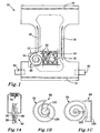
- the open diaper 10 according to the present invention comprising wetness detecting means 30 is shown in Figure 1 in cut-away view.
- the present invention requires the use of electrically active materials 50 which can be printed.
- electrically active is used in the present context to mean materials which can conduct electrical charge and thus be used to fabricate electrical circuits or components thereof. Although a border between conductive and semi-conductive active materials is not clearly defined, the present invention includes both aspects, to the extent that they fulfil the requirements of the electrical circuit in question. Electrically active materials 50 are not restricted to pure materials, but include mixtures of electrically active materials 50, in whatever form.
- the electrically active materials 50 are printable. This means that the materials 50 are stable in liquid or solution form (i.e. can be solution-processed) and can be applied to a surface (in this case, a component of the absorbent article) in a desired pattern or form, which pattern or form is then retained after the material dries or cools.
- the electrically active materials 50 should also have mechanical properties which make them tolerant to flexing and tension which might be present in the absorbent article 10. They should also be stable to the environment in which they are to be used (i.e. stable to humidity, sunlight, oxygen etc.). Printing can be carried out by standard techniques known in the art, such as laser printing, inkjet printing, thermal printing, screen printing, offset printing, relief print and rotogravure.
- Conductive polymers are one class of electrically active materials 50 which are printable. Such polymers generally have structures in which the electrons are heavily delocalised, e.g. through ⁇ -bonds (double or triple bonds), aromatic systems or electron lone pairs which are included in the polymer chain. The electrons are therefore free to move along the polymer structure. The extent of delocalisation determines the degree of conductivity - polymers which have poorly delocalised electrons will be less conducting than those having continuous delocalisation across the entire polymer structure. Examples of conducting polymers are polyphenylene-vinylene (PPV), polyaniline (PANI) and polypyrrole (PPy). The structures of these polymers are given below.
- electrical, mechanical and chemical properties of such polymers can be adjusted as desired, by, for example, cross-linking or substitution of the polymer, or combining them with other materials before printing. In many cases, these polymers need to be protected from air and humidity by laying a printed barrier film over the polymers, or by depositing the polymers simultaneously with a barrier matrix.
- Another class of printable electrically active materials 50 are particle suspensions. These materials comprise small particles of an electrically-conducting material (e.g. a metal such as silver or copper, or a non-metal such as graphite) which are suspended in an organic solvent or carrier.
- the particles provide the material with the desired conductivity, while the organic solvent or carrier provides the required physical properties (e.g. plasticity, coefficient of thermal expansion, ease of application, viscosity and fracture toughness).
- the organic solvent or carrier may also contribute to the electrical properties of the electrically active material.
- the organic solvent may evaporate after printing, in which case, the particles remain on the printed surface. Alternatively, the organic carrier hardens after printing, so that the particles are trapped within the carrier. Examples of the latter embodiment are epoxy resins.
- Such particle suspensions are commercially available from DuPont electronics or T ⁇ BY Sweden.
- the printable electrically active materials 50 of the invention may comprise a mixture of the above-described particle suspensions and conductive polymers.
- electrically active materials 50 it is possible for different electrically active materials 50 to be printed in different regions or components of an absorbent article, depending on the type of electrical circuit which is required. By repeatedly printing electrically active materials 50 (optionally having different electrical properties) on the same region or component, it is possible to build up layers of electrically active material on top of each other. Alternatively, electrical components can be fabricated with intervening layers of the components of the absorbent article, so that a sandwich-type structure is created. This can be seen in the cut-away view in Fig. 1 . The components of the absorbent article 10 may be selected or treated to be permeable or resistant to the electrically active material. All of these approaches allow complex electrical circuits to be manufactured.
- the detecting means 30 comprises an electrical circuit 40, which is integrally formed into said article 10, said at least one electrical circuit 40 being fabricated from an electrically active material 50 which has been printed onto one or more components of the absorbent article 10.
- circuits fall into two general classes - active circuits, which comprise a power source as a component of the circuit, and passive circuits, which do not comprise a power source as one of their components, but act in response to an externally-applied power source.
- the electrical circuit 40 is an integral part of the absorbent article 10 and cannot be removed or disassembled without destroying either the absorbent article 10 or the electrical circuit 40 or both. In certain circumstances, the electrically active material 50 can penetrate into the components of the absorbent article 10.
- Figure 1a shows a circuit diagram of a tuned circuit (also called an RLC circuit) which consists of a capacitor 60 and an inductor 70. There will naturally be a certain amount of resistance from the circuit; alternatively, resistors may be included in parallel or in series with the capacitor 60 and the inductor 70.
- a tuned circuit also called an RLC circuit
- Cellulose in paper and cotton products has a relative permittivity of approximately 6.5.
- Unimpregnated dry tissue (kraft) paper has a relative permittivity of around 2.1.
- Polymers such as polyethylene and polypropylene have relative permittivities in a range of substantially 2.2 - 2.5. (Reference: Kaye & Laby, Tables of Physical and Chemical Constants, 15th ed. 1986 )
- a tuned circuit such as that illustrated in Fig. 1 a resonates at a natural resonant frequency, which can be adjusted through choice of capacitor and inductor variables listed above.
- a change in the moisture-content of the absorbent article 10 influences the resonant frequency f 0 of the electrical circuit 40.
- the moisture content of the absorbent article 10 may influence the capacitance of the capacitor 60.
- a water-swellable material may be present in the dielectric layer 80 between the plates 90 of the capacitor 60, so that, upon wetting, the distance d increases, and the capacitance decreases.
- liquid-absorbent material such as superabsorbent polymer (SAP), cellulose or any other liquid-absorbent material
- SAP superabsorbent polymer
- cellulose any other liquid-absorbent material
- the absorption of liquid into the liquid-absorbent material has the effect of increasing the relative permittivity ( ⁇ r ) of the liquid-absorbent material (as water has a high relative permittivity), thus increasing the capacitance of the capacitor 60.
- a water-soluble substance such as an inorganic salt may be present in the dielectric layer 80 between the plates 90 of the capacitor 60.
- the water-soluble substance dissolves upon contact with liquid and thus the capacitance of the capacitor 24 will change, and the resonant frequency f 0 of the circuit will alter.
- a change in resistance of the circuit will change the resonant frequency f 0 of the circuit.
- a change in the moisture-content of the absorbent article 10 influences the resistance of the electrical circuit 40. This may be, for example, achieved by using conductive polymer materials protected by a water-soluble barrier film (e.g. an epoxy material). Upon wetting, the film dissolves and water, salts and urea will react with the conductive polymer material, changing the resistance of the circuit and thereby the resonant frequency f 0 .
- a water-soluble barrier film e.g. an epoxy material
- FIG. 1a When printed onto a component of the absorbent article, such as a paper sheet or a plastic film, the circuit illustrated diagrammatically in Fig. 1a may be in the form shown in Fig. 1b.
- Figure 1b shows an inductor 70 which comprises a flat spiral printed in electrically active material 50 on a component of the absorbent article 10.
- the spiral typically has between 5-20 turns.
- the spiral has a first central area 110.
- a corresponding second central area 120 is printed on the opposite face of the component of the absorbent article - together these two central areas 110, 120 constitute the plates of the capacitor 90 which are separated by the component of the absorbent article 10.
- the circuit is completed by electrically active material which connects the second central area 120 to the outer end of the spiral, through the component of the absorbent article 10.
- FIG. 1c illustrates the inductor 70 which comprises a flat spiral form as in Figure 1b .
- the capacitor 60 is formed by first 160 and second 170 areas lying on opposite faces of the component of the absorbent article 10, outside the area comprised by the spiral. Together, these first 160 and second 170 areas constitute the plates of the capacitor 90.
- An alternative way in which the moisture-content of the absorbent article 10 can influence the resonant frequency f 0 of the electrical circuit 40 is through destruction, namely disablement, of the electrical circuit 40.
- a change in the moisture content of the absorbent article 10 destroys the resonant frequency f 0 of the electrical circuit 40.
- This may be achieved through an electrical circuit as illustrated in Figure 2a .
- Such a circuit comprises a weak point 200, which for instance comprises water-soluble electrically active material, or electrically active material which is printed on a water-soluble component.
- An absorbent article comprising such the electrical circuit illustrated in Figure 2a will resonate at its resonant frequency upon application of an external RF field.
- the electrical circuit 40 Upon contact with a liquid, however, the electrical circuit 40 is physically broken and by virtue of the weak point 200 becoming a high-resistance or substantially open-circuit, the electrical circuit 40 will not then resonate upon application of an external RF field.
- Figure 2b shows how the electrical circuit 40 illustrated diagrammatically in Fig. 2a may be printed.
- the electrical circuit 40 has essentially the same form as that shown in Figure 1b , with an inductor 70 which comprises a flat spiral and two central areas 300, 310 which constitute the plates 90 of the capacitor 60.
- the circuit shown in Figure 2b includes a weak point 200 which is broken upon contact with a liquid.
- the electrical circuit 40 may comprise a sensor 400 connected in parallel or in series with the capacitor 60 and the inductor 70.
- a change in the moisture-content of the absorbent article 10 influences the conductance of a current across the sensor 400.
- a circuit diagram which illustrates the use of a sensor 400 is shown in Figure 3a .
- Printed sensors 400 may take a number of forms.
- One possibility is to print the sensor 400 in a sandwich structure similar to those described for capacitors 24 above. This construction requires two layers of electrically active material 50 separated by a dielectric material.
- the sensor may have an interdigitated construction, in which electrically active material 50 is printed as a pair of "fork" shapes in which the prongs of the forks are interleaved, but without electrical contact between the prongs.
- This layout is advantageous, as it can be printed in one layer, making it less expensive to print than multiple layers.
- the wetness detecting means 30 is printed on a component of the absorbent article 10 which lies adjacent to the inner surface of a backsheet 14 of the absorbent article 10..
- the principles involved in the sensor 400 are similar to those involved in the capacitor 60.
- the permittivity of the sensor 400 changes. This may be achieved by the physical dimensions or the relative permittivity of the sensor 400 changing upon contact with liquid.
- the resonant frequency f 0 of the tuned -circuit changes.
- FIG. 4 shows a circuit diagram of a more advanced electrical circuit, indicated generally by 500, which may make up the wetness detecting means 30.
- a major circuit comprises a first inductor 70a, a first capacitor 60a and a sensor 400 connected in parallel, with a diode 410 located in series with the first inductor 70a.
- the sensor 400 is connected in parallel via a transistor 420 with a minor circuit which is itself a tuned circuit comprising a second inductor 70b and a second capacitor 60b.
- the transistor 420 is further connected via a high resistance bias resistor 430and a third inductor 70c.
- the circuit 500 is subjected to an alternating magnetic field at a first frequency f 1 : the first frequency is beneficially in a range of 10kHz to 100kHz.
- the first inductor 70a is arranged to include sufficient turns and be of sufficient area A so that a signal induced across the first inductor 70a has an amplitude in the order of a few volts.
- the diode 410 is operable to rectify the signal so as to generate a working supply potential in operation across the first capacitor 60a.
- the transistor 420 of NPN type or MOS type is biased into a non-conducting state by virtue of the bias resistor 430; in such a non-conducting state, the transistor 420 is hindered from oscillating.
- the sensor 400 When a soiling event occurs, the sensor 400 becomes conductive, causing the transistor 420 to be biased into an active part of its characteristic: in consequence, positive feedback occurs between the second and third inductors 70b, 70c causing the transistor to oscillate at a frequency f 2 defined by the second inductor 70b and the second capacitor 60b.
- the second frequency f 2 is substantially at least an order of magnitude greater than the frequency f 1 of exciting magnetic field applied
- Figure 5 illustrates how the electrical circuit 500 of Figure 4 might be printed on an absorbent article 10.
- the first inductor 70a comprises a relatively large number of coils (e.g. 50 - 500), and may be printed together with the first capacitor 60a in the same way as the circuits illustrated in Figures 1-3 .
- the sensor 400 may be printed in the same way as illustrated in Fig. 3 .
- Diode 410 can be printed laying down multiple layers of electrically active material with selected electrical properties so as to build the required p-n junctions.
- layers of electrically active material with different electrical properties can be used to build up transistor 420, either in MOS or bipolar implementation.
- a gate electrode is printed onto a substrate using gold nanocrystals. This is followed by low-temperature annealing, and then polymer dielectric is deposited via inkjet printing. Source/drain contacts are then printed, again using gold nanocrystals.
- the second and third inductors 70c, 70c comprise fewer coils than the first inductor (e.g. 5-20 coils) and may be printed together with the second capacitor 60b in the same way as the circuits illustrated in Figures 1-3 . It is desirable that the first inductor 70a is distant from the second and third inductors 70b, 70c, so that coupling between the first inductor 70a and the second and third inductors 70b, 70c is minimised. For instance, the first inductor 70a could be located on the rear of the absorbent article 10, while the second and third inductors 70b, 70c are located on the front of the absorbent article 10.
- the senor 400 is printed in the crotch region of the absorbent article 10, which is the area in which wetting is easiest to detect.
- High frequency radiation at the frequency f 2 can be detected in an external detector device (e.g. transponder unit 700) which is selectively responsive to emitted radiation from the article 10 at the frequency f 2 .
- the wetness detecting means 30 may be active, i.e. it comprises a power source. Although such active wetness detecting means 30 are more complicated, they can provide a much wider functionality than passive wetness detecting means 18.
- a printed electrical circuit 40 can be divided into five major parts. These are printed batteries, printed antennae, printed memory circuits, printed logic circuits and printed sensors. The most essential components are printed batteries, printed antennae and printed sensors.
- Printed batteries comprise an electrolyte sandwiched between two electrodes.
- the electrolyte is usually in the form of a gel which is sealed so as to avoid leakage.
- Suitable electrolytes are carbon-zinc electrolytes or zinc-manganese dioxide.
- One possible structure for a printed battery is alternating layers of zinc and manganese dioxide-based cathode and anode layers.
- Printed batteries may have a thickness which is generally between 0.5 and 1mm, and, if circular in form, a diameter which is between 25 and 50mm. Typical output voltages are 1.5V; the same as many conventional batteries. They are manufactured by standardised printing, drying and laminating equipment and processes. Printed batteries are commercially available from e.g. PowerPaper Ltd.
- the battery itself may function as a sensor.
- Printed batteries can be made in such a way that they are inactive until contacted by a liquid. Upon activation (wetting), the battery sends a current to a circuit including one or more antennae. This generates an RF signal.
- Such batteries remove the need for a separate sensor, and are storage-stable.
- Antennae are available as printed antennae, inlays or completed labels. Antennae are commonly printed with silver-based particle suspensions, such as those described above, which are compatible with both paper and polymer components of an absorbent article. Such antennae can provide performance to match traditional copper or aluminium antennae.
- An example of a commercially available printed antenna is FleX Wing produced by Precisia LLP.
- Active wetness detecting means 30 may be designed to ensure long life of the battery, e.g. by pulsing the power supplied by the battery, or by using the battery only to power the memory and using a passive wetness detecting means 30 for generating an RF signal.
- the printed logic circuit may be used to monitor the printed sensor at given time intervals and save the result in the printed memory. Additionally, if the active wetness detecting means 30 comprises more than one printed sensor in different locations in the absorbent article 10, the logic circuit can be used to compare the signals from the sensors and gather data on the nature, extent and location of the wetness in the absorbent article 10. Particularly of interest are wetness detecting means 30 which provide a quantitative measure of the status of an absorbent article, rather than a simple on/off measure.
- Printed memory circuits can be used to maintain a record of the status of the absorbent article 10. Preferably, the memory does not require constant power supply.
- the absorbent articles 10 of the present invention are used in combination with an RF transmitter/receiver (transponder) unit 700 ( Fig. 6 ).
- the transponder unit 700 comprises an inductor coil which generates an RF field; an antenna which detects an RF signal generated by an electrical circuit 40; indicating means such as one or more audible sounders, indicator lights, display screen etc.; a power source (e.g. batteries) and circuitry for controlling the inductor coil, the antenna and the indicating means.
- the indicating means may be a loudspeaker which generates an audible signal or an LED which lights up when the absorbent article 10 needs to be changed.
- the status of an absorbent article 10 may be displayed on a display screen which forms part of the transponder unit 700.
- the transponder unit 700 is preferably a portable hand-held device, so that the status of a wearer's absorbent article 10 can be determined easily and quickly without disturbing the wearer.
- the transponder unit 700 generates an RF field which corresponds to the resonant frequency of the electrical circuit 40.
- the electrical circuit 40 resonates, and the RF signal thus produced can be detected by the transponder unit 700.
- the RF signal generated by the electrical circuit 40 is optionally beneficially in the region 10 - 100kHz.
- it is advantageous that the RF field generated by the transponder unit is pulsed, so that any weak RF signals generated by the electrical circuit 40 are not obscured by the RF field generated by the transponder unit 700.
- the electrical circuit 40 will continue to resonate for a short while after the RF field generated by the transponder unit 700 is interrupted, so that weak RF signals can be detected at the unit 700.
- the transponder unit 700 may include a threshold, below which an RF signal generated by the electrical circuit 40 will not activate the indicating means. This will provide advantages in that an absorbent article 10 need not be changed after every soiling event, but rather the caregiver can wait until a certain level of wetness has been reached.
- the transponder unit 700 may be arranged so as to scan a range of frequencies. In this way, small deviations in the resonant frequency of the electrical circuit 40 can be accommodated. Additionally, by scanning a range of frequencies, the progression of an electrical circuit 40 from an initial resonant frequency to a final resonant frequency can be seen, which also allows the caregiver to wait until a certain level of wetness has been reached before changing the absorbent article.
- the transponder unit 700 comprises a memory unit, in which data concerning the number of times an absorbent article is changed can be stored. This information can be downloaded to a computer and then used by caregivers to determine statistics or to make predictions for future consumption of absorbent articles. Furthermore, if a particular electrical circuit 40 provides a particular resonant frequency which can be correlated with a particular wearer, wearer-specific data can be gathered.
- the wetness detecting means 30 of the invention may comprise a plurality of sensors 400 located in mutually different regions of the absorbent article 10. In this way, the nature, extent and location of the wetness in the absorbent article 10 can be monitored. It is preferred that the sensors 400 are located in the crotch region of the absorbent article 10, where wetness is most likely to be detected. Additionally or alternatively, the absorbent article 10 may comprise a plurality of wetness detecting means 30 located in mutually different regions of the absorbent article 10. If the wetness detecting means 30 is of the "short-circuit" type (as shown and described in Fig. 2A-2B ), it is preferably located in the crotch region of the absorbent article, where wetness is most likely to be detected. If, however, the wetness detecting means 30 is not of this type (e.g. if it is moisture-sensitive) it is advantageous for it not to be located in the crotch portion, so that it is not saturated immediately upon soiling of the absorbent article 10.
Claims (14)
- Article absorbant (10) comportant au moins un moyen de détection d'humidité (30), dans lequel ledit moyen de détection d'humidité (30) comprend au moins un circuit électrique (40,), ledit circuit électrique (40) au minimum unique étant réalisé d'un seul tenant dans ledit article (10), ledit circuit électrique (40) au minimum unique étant fabriqué à partir d'un matériau actif électriquement (50) qui a été imprimé sur un ou plusieurs composants de l'article absorbant (10), caractérisé en ce que le moyen de détection d'humidité (30) est actif, par exemple du fait qu'il comprend une source d'énergie.
- Article absorbant selon la revendication 1 caractérisé en ce que le circuit électrique (40) comprend un condensateur (60) et un inducteur (70) reliés en parallèle ou en série, une variation de la teneur en humidité de l'article absorbant (10) ayant une influence sur la fréquence de résonance du circuit électrique (40).
- Article absorbant selon la revendication 2 caractérisé en ce qu'une variation de la teneur en humidité de l'article absorbant (10) a une influence sur la capacité du condensateur (60).
- Article absorbant selon la revendication 3 caractérisé en ce que le condensateur (60) comprend un matériau (80) absorbant les liquides inclus entre les plaques (90) du condensateur (60).
- Article absorbant selon la revendication 3 caractérisé en ce que le condensateur (60) comprend une substance (80) soluble dans l'eau incluse entre les plaques (90) du condensateur (60).
- Article absorbant selon l'une quelconque des revendications 1 à 5 caractérisé en ce qu'une variation de la teneur en humidité de l'article absorbant (10) a une influence sur la résistance du circuit électrique (40).
- Article absorbant selon la revendication 2 caractérisé en ce qu'une variation de la teneur en humidité de l'article absorbant (10) détruit la fréquence de résonance du circuit électrique (40).
- Article absorbant selon l'une quelconque des revendications 2 à 7 caractérisé en ce que le circuit électrique (40) comprend en outre un capteur (400) connecté en parallèle ou en série au condensateur (60) et à l'inducteur (70), une variation de la teneur en humidité de l'article absorbant (10) ayant une influence sur la conduction d'un courant traversant le capteur (400).
- Article absorbant selon la revendication 1 caractérisé en ce que le moyen de détection d'humidité (30) comporte au moins un composant imprimé choisi dans le groupe comprenant : un accumulateur imprimé, une antenne imprimée, un circuit de mémoire imprimé, un circuit logique imprimé et un capteur imprimé.
- Article absorbant selon la revendication 9 caractérisé en ce que le composant imprimé au minimum unique est choisi dans le groupe comprenant : un accumulateur imprimé, une antenne imprimée et un capteur imprimé.
- Article absorbant selon l'une quelconque des revendications 1 à 10 caractérisé en ce que le moyen de détection d'humidité (30) comprend une pluralité de capteurs (400) placés dans des zones différentes les unes des autres de l'article absorbant (10).
- Article absorbant selon l'une des revendications 1 à 11 caractérisé en ce que l'article absorbant (10) comprend une pluralité de moyens de détection d'humidité (30) placés dans des zones différentes les unes des autres de l'article absorbant (10).
- Article absorbant selon l'une quelconque des revendications 1 à 12 caractérisé en ce que le moyen de détection d'humidité (30) est imprimé sur un composant de l'article absorbant (10) qui est situé à proximité de la surface intérieure d'une feuille arrière (14) de l'article absorbant (10).
- Article absorbant selon l'une quelconque des revendications 1 à 6 ou 8 à 12 dans lequel le moyen de détection d'humidité (30) donne une mesure quantitative de l'état d'un article absorbant (10).
Applications Claiming Priority (1)
| Application Number | Priority Date | Filing Date | Title |
|---|---|---|---|
| PCT/SE2005/001907 WO2007069945A1 (fr) | 2005-12-12 | 2005-12-12 | Article absorbant comprenant des moyens de détection d'humidité |
Publications (3)
| Publication Number | Publication Date |
|---|---|
| EP1959901A1 EP1959901A1 (fr) | 2008-08-27 |
| EP1959901A4 EP1959901A4 (fr) | 2011-06-01 |
| EP1959901B1 true EP1959901B1 (fr) | 2015-02-25 |
Family
ID=38163165
Family Applications (1)
| Application Number | Title | Priority Date | Filing Date |
|---|---|---|---|
| EP05819070.3A Active EP1959901B1 (fr) | 2005-12-12 | 2005-12-12 | Article absorbant comprenant des moyens de détection d'humidité |
Country Status (9)
| Country | Link |
|---|---|
| US (1) | US20080300559A1 (fr) |
| EP (1) | EP1959901B1 (fr) |
| JP (1) | JP2009519051A (fr) |
| CN (1) | CN101304715B (fr) |
| AU (1) | AU2005339180A1 (fr) |
| BR (1) | BRPI0520789B8 (fr) |
| CA (1) | CA2630406A1 (fr) |
| DK (1) | DK1959901T3 (fr) |
| WO (1) | WO2007069945A1 (fr) |
Families Citing this family (87)
| Publication number | Priority date | Publication date | Assignee | Title |
|---|---|---|---|---|
| US7977529B2 (en) | 2004-11-03 | 2011-07-12 | Fred Bergman Healthcare Pty Ltd. | Incontinence management system and diaper |
| BRPI0707961A2 (pt) * | 2006-02-28 | 2011-05-10 | Coloplast As | mÉtodo para detectar o desprendimento de um curativo, curativo apropriado para aplicar o mÉtodo, conjunto sensor e blindagem para reduzir o acoplamento capacitivo a partir das vizinhanÇas ambientais para os eletrodos do curativo |
| US8334425B2 (en) * | 2007-06-27 | 2012-12-18 | Kimberly-Clark Worldwide, Inc. | Interactive garment printing for enhanced functionality of absorbent articles |
| US8400171B2 (en) * | 2007-11-16 | 2013-03-19 | The Boeing Company | Transmission line moisture sensor |
| DE102008013090A1 (de) * | 2008-03-07 | 2009-09-10 | Fresenius Medical Care Deutschland Gmbh | Vorrichtung und Verfahren zur Überwachung eines Zugangs zu einem Patienten, insbesondere eines Gefäßzugangs bei einer extrakorporalen Blutbehandlung |
| US8044258B2 (en) | 2008-06-27 | 2011-10-25 | Kimberly-Clark Worldwide, Inc. | Absorbent article featuring leakage warning |
| JP2011045613A (ja) * | 2009-08-28 | 2011-03-10 | Koa Corp | おむつ濡れの検知装置 |
| SE534533C2 (sv) | 2009-10-07 | 2011-09-27 | Pampett Ab | Metod och system för detektering av fukt vid en absorberande artikel |
| US9655787B2 (en) * | 2010-11-19 | 2017-05-23 | Covenant Ministries Of Benevolence | Stacked moisture sensing device |
| GB201022028D0 (en) | 2010-12-23 | 2011-02-02 | Sca Hygiene Prod Ab | Tool for analysing liquid discharge data in an absorbent article, an absorbent article adapted for liquid dicharge data collection and a control unit |
| US10271998B2 (en) | 2011-06-03 | 2019-04-30 | The Procter & Gamble Company | Sensor systems comprising anti-choking features |
| US9241839B2 (en) * | 2011-07-15 | 2016-01-26 | Kimberly-Clark Worldwide, Inc. | Absorbent article fullness indicator |
| US8826473B2 (en) | 2011-07-19 | 2014-09-09 | Hill-Rom Services, Inc. | Moisture detection system |
| EP2739254B1 (fr) * | 2011-08-01 | 2016-11-16 | Fred Bergman Healthcare Pty Ltd | Capteur d'humidité capacitif et procédé de fabrication associé |
| US9681996B2 (en) * | 2011-08-11 | 2017-06-20 | 3M Innovative Properties Company | Wetness sensors |
| US8978452B2 (en) * | 2011-08-11 | 2015-03-17 | 3M Innovative Properties Company | Wetness sensor using RF circuit with frangible link |
| WO2013033724A1 (fr) * | 2011-09-01 | 2013-03-07 | Mc10, Inc. | Dispositif électronique pour détection d'une condition de tissu |
| US9278033B2 (en) * | 2011-11-22 | 2016-03-08 | Kimberly-Clark Worldwide, Inc. | Contactless passive sensing for absorbent articles |
| US8889944B2 (en) * | 2011-12-06 | 2014-11-18 | Kimberly-Clark Worldwide, Inc. | Sensor products using wicking materials |
| US20140015644A1 (en) * | 2011-12-27 | 2014-01-16 | The Gillette Company | Apparatus and Method for Providing Product Information |
| US20130162402A1 (en) * | 2011-12-27 | 2013-06-27 | Mathias Amann | Apparatus and Method for Providing Product Information |
| US20150164703A1 (en) * | 2012-06-15 | 2015-06-18 | Ithealth Co., Ltd. | Excreta detecting sensor and detecting device using electrically-conductive fibrous conducting wire |
| WO2014015192A1 (fr) | 2012-07-18 | 2014-01-23 | Martello Jeannette | Tampon hygiénique indicateur de temps |
| US20140276504A1 (en) | 2013-03-13 | 2014-09-18 | Hill-Rom Services, Inc. | Methods and apparatuses for the detection of incontinence or other moisture, methods of fluid analysis, and multifunctional sensor systems |
| US20150130637A1 (en) * | 2013-11-11 | 2015-05-14 | Trackblue, Llc | Wireless Moisture Sensing Device, System, and Related Methods |
| US10438476B2 (en) | 2013-06-26 | 2019-10-08 | Vypin, LLC | Wireless hand hygiene tracking system and related techniques |
| US10121028B2 (en) | 2013-06-26 | 2018-11-06 | Vypin, LLC | Asset tag apparatus and related methods |
| US10572700B2 (en) | 2013-06-26 | 2020-02-25 | Vypin, LLC | Wireless asset location tracking system and related techniques |
| GB2531224B (en) * | 2013-08-08 | 2020-02-12 | Procter & Gamble | Sensor systems for absorbent articles comprising sensor gates |
| JP6098724B2 (ja) * | 2013-08-13 | 2017-03-22 | 株式会社村田製作所 | 温湿度センサ |
| JP6376527B2 (ja) * | 2013-12-12 | 2018-08-22 | 国立大学法人山形大学 | 液体検知装置 |
| EP3111202B1 (fr) * | 2014-02-27 | 2021-07-14 | 3M Innovative Properties Company | Plaque de capteur flexible et son utilisation |
| EP3117414A4 (fr) * | 2014-03-12 | 2017-03-29 | Hill-Rom Services, Inc. | Procédé et appareil de détection de l'humidité et système de capteur multifonctionnel |
| CN104851245A (zh) * | 2014-03-27 | 2015-08-19 | 北汽福田汽车股份有限公司 | 一种油液渗漏检测报警装置 |
| US10531977B2 (en) | 2014-04-17 | 2020-01-14 | Coloplast A/S | Thermoresponsive skin barrier appliances |
| FI125745B (fi) * | 2014-07-18 | 2016-01-29 | Maricare Oy | Anturijärjestely |
| US10477354B2 (en) | 2015-02-20 | 2019-11-12 | Mc10, Inc. | Automated detection and configuration of wearable devices based on on-body status, location, and/or orientation |
| US9918884B2 (en) | 2015-04-22 | 2018-03-20 | Kpr U.S., Llc | Remote monitoring of absorbent article |
| WO2016187568A1 (fr) * | 2015-05-21 | 2016-11-24 | Wave Sensor, Inc. | Surveillance d'événements d'incontinence |
| CN105686881B (zh) * | 2015-07-16 | 2019-01-22 | 深圳市华阳微电子股份有限公司 | 尿布传感器的储存盒、储存方法及安装方法 |
| US10653567B2 (en) | 2015-11-16 | 2020-05-19 | Hill-Rom Services, Inc. | Incontinence detection pad validation apparatus and method |
| US11707387B2 (en) | 2015-11-16 | 2023-07-25 | Hill-Rom Services, Inc. | Incontinence detection method |
| US11147719B2 (en) | 2015-11-16 | 2021-10-19 | Hill-Rom Services, Inc. | Incontinence detection systems for hospital beds |
| EP3420732B8 (fr) | 2016-02-22 | 2020-12-30 | Medidata Solutions, Inc. | Système, dispositifs et procédé pour l'émission de données et d'énergie sur le corps |
| JP6806295B2 (ja) * | 2016-02-23 | 2021-01-06 | 国立大学法人山形大学 | おむつ用液体検知センサおよび液体検知装置 |
| US10285871B2 (en) | 2016-03-03 | 2019-05-14 | The Procter & Gamble Company | Absorbent article with sensor |
| US10299723B2 (en) * | 2016-06-13 | 2019-05-28 | Verily Life Sciences Llc | Ultra-low power one-shot hydration sensing system |
| US20180146906A1 (en) | 2016-11-29 | 2018-05-31 | Hill-Rom Services, Inc. | System and method for determining incontinence device replacement interval |
| CN108938209B (zh) * | 2017-05-18 | 2021-10-19 | 赖中平 | 无线感应式尿布及其监控设备 |
| JP2020524063A (ja) * | 2017-06-05 | 2020-08-13 | クレイダース カンパニー,リミテッド | 吸収用品の製造方法 |
| EP3427709A1 (fr) | 2017-07-13 | 2019-01-16 | Assistr Digital Health Systems GmbH | Appareil de surveillance d'humidité pour surveillance de l'incontinence |
| EP3451235B1 (fr) | 2017-08-29 | 2021-06-02 | Hill-Rom Services, Inc. | Incrustation d'étiquette rfid pour patin de détection de l'incontinence |
| US11399988B2 (en) * | 2017-09-11 | 2022-08-02 | Toray Industries, Inc. | Wireless communication device, diaper and moisture detecting system |
| DE102017125323A1 (de) * | 2017-10-27 | 2019-05-02 | Mondi Ag | Folienabschnitt, flüssigkeitsabsorbierender Hygieneartikel und Verfahren zur Kontrolle eines flüssigkeitsabsorbierenden Hygieneartikels |
| US10799385B2 (en) | 2017-12-22 | 2020-10-13 | Coloplast A/S | Ostomy appliance with layered base plate |
| US11471318B2 (en) | 2017-12-22 | 2022-10-18 | Coloplast A/S | Data collection schemes for a medical appliance and related methods |
| WO2019120452A1 (fr) | 2017-12-22 | 2019-06-27 | Coloplast A/S | Pièce d'accouplement dotée d'une charnière pour une plaque de base de stomie et partie d'assemblage de capteur |
| WO2019120439A1 (fr) | 2017-12-22 | 2019-06-27 | Coloplast A/S | Procédés d'étalonnage pour outils d'appareillage stomique |
| US11607334B2 (en) | 2017-12-22 | 2023-03-21 | Coloplast A/S | Base plate for a medical appliance, a monitor device and a system for a medical appliance |
| JP2021508269A (ja) | 2017-12-22 | 2021-03-04 | コロプラスト アクティーゼルスカブ | オストミー装具用のベースプレート及びベースプレート用のセンサ組立体部分、並びに、ベースプレート及びセンサ組立体部分を製造するための方法 |
| EP3727222B1 (fr) | 2017-12-22 | 2024-05-08 | Coloplast A/S | Module ensemble capteurs pour appareil de stomie, et procédé de fabrication d'un module ensemble capteurs |
| US11628084B2 (en) | 2017-12-22 | 2023-04-18 | Coloplast A/S | Sensor assembly part and a base plate for a medical appliance and a device for connecting to a base plate or a sensor assembly part |
| US11622719B2 (en) | 2017-12-22 | 2023-04-11 | Coloplast A/S | Sensor assembly part, base plate and monitor device of a medical system and associated method |
| US10849781B2 (en) | 2017-12-22 | 2020-12-01 | Coloplast A/S | Base plate for an ostomy appliance |
| US10500084B2 (en) | 2017-12-22 | 2019-12-10 | Coloplast A/S | Accessory devices of an ostomy system, and related methods for communicating leakage state |
| US11819443B2 (en) | 2017-12-22 | 2023-11-21 | Coloplast A/S | Moisture detecting base plate for a medical appliance and a system for determining moisture propagation in a base plate and/or a sensor assembly part |
| LT3727232T (lt) | 2017-12-22 | 2022-04-25 | Coloplast A/S | Ostomijos prietaisas su atrankiniais jutiklio taškais ir susiję būdai |
| EP3727236A1 (fr) | 2017-12-22 | 2020-10-28 | Coloplast A/S | Partie d'assemblage de capteur et plaque de base pour appareillage de stomie et procédé de fabrication d'une partie d'assemblage de capteur et d'une plaque de base |
| US11559423B2 (en) | 2017-12-22 | 2023-01-24 | Coloplast A/S | Medical appliance system, monitor device, and method of monitoring a medical appliance |
| EP3727242B1 (fr) | 2017-12-22 | 2022-03-09 | Coloplast A/S | Dispositif de surveillance d'un système de stomie doté d'un connecteur destiné à être couplé à la fois à une plaque de base et à un dispositif accessoire |
| AU2018391323B2 (en) | 2017-12-22 | 2024-03-21 | Coloplast A/S | Base plate and sensor assembly of an ostomy system having a leakage sensor |
| US11654043B2 (en) | 2017-12-22 | 2023-05-23 | Coloplast A/S | Sensor assembly part and a base plate for a medical appliance and a method for manufacturing a base plate or a sensor assembly part |
| LT3727234T (lt) | 2017-12-22 | 2022-04-25 | Coloplast A/S | Ostomijos prietaisas su kampinio nuotekio aptikimu |
| EP3727247B1 (fr) | 2017-12-22 | 2022-04-20 | Coloplast A/S | Outils et procédés pour placer un appareil de stomie sur un utilisateur |
| WO2019161861A1 (fr) | 2018-02-20 | 2019-08-29 | Coloplast A/S | Partie d'ensemble capteur et plaque de base pour un appareil de stomie et dispositif de connexion à une plaque de base ou à une partie d'ensemble capteur |
| US20190262191A1 (en) * | 2018-02-26 | 2019-08-29 | Gallop Creation USA Inc. | Smart diaper having pre-treated material for accurate sensing of a soiled area |
| US20210236346A1 (en) * | 2018-04-20 | 2021-08-05 | Pampett Ab | A Method of Manufacturing a Device for Detecting Moisture at an Absorbent Article |
| CN112074257A (zh) | 2018-05-04 | 2020-12-11 | 宝洁公司 | 用于监控婴儿基本需求的传感器装置和系统 |
| US10945892B2 (en) | 2018-05-31 | 2021-03-16 | Hill-Rom Services, Inc. | Incontinence detection system and detectors |
| US11051996B2 (en) | 2018-08-27 | 2021-07-06 | The Procter & Gamble Company | Sensor devices and systems for monitoring the basic needs of an infant |
| US11612512B2 (en) | 2019-01-31 | 2023-03-28 | Coloplast A/S | Moisture detecting base plate for an ostomy appliance and a system for determining moisture propagation in a base plate and/or a sensor assembly part |
| US11517469B2 (en) | 2019-01-31 | 2022-12-06 | Coloplast A/S | Base plate and sensor assembly part of an ostomy system having a moisture sensor |
| US11950987B2 (en) | 2019-05-21 | 2024-04-09 | Hill-Rom Services, Inc. | Manufacturing method for incontinence detection pads having wireless communication capability |
| JP6929501B1 (ja) * | 2020-06-09 | 2021-09-01 | 正人 土屋 | 濡れ検知センサー、濡れ報知装置及び濡れ検知方法 |
| HUE062259T2 (hu) * | 2020-07-15 | 2023-10-28 | Hollister Inc | Ellenállás érzékelõ szivárgás helyeinek azonosítására osztómiás rendszerben |
| USD970017S1 (en) | 2020-08-25 | 2022-11-15 | Coloplast A/S | Ostomy appliance monitor |
| CN113197724B (zh) * | 2021-04-23 | 2022-07-29 | 嘉兴聚鑫隆科技有限公司 | 一种智能检测尿布 |
Family Cites Families (36)
| Publication number | Priority date | Publication date | Assignee | Title |
|---|---|---|---|---|
| US36484A (en) * | 1862-09-16 | Improvement in fabrics for roofing | ||
| GB1352685A (en) * | 1970-04-29 | 1974-05-08 | Nat Res Dev | Incontinence measurement |
| US4539559A (en) * | 1982-03-29 | 1985-09-03 | Hugh Kelly | Portable, disposable warning device for detecting urine-wet undergarments |
| JPS60181311U (ja) * | 1984-05-15 | 1985-12-02 | ニツポン高度紙工業株式会社 | 水分量を感知可能な使いすておむつ |
| DE3437950A1 (de) * | 1984-10-17 | 1985-04-18 | Arno H. Dipl.-Ing. 7141 Beilstein Taruttis | Einrichtung zum bestimmen des feuchtigkeitsgehalts in babyhoeschenwindeln waehrend des tragens |
| US4800370A (en) * | 1985-10-07 | 1989-01-24 | I E Sensors, Inc. | Wetness detection system |
| US5197958A (en) * | 1992-04-01 | 1993-03-30 | Howell Wesley A | Wetness indicating diaper |
| US6045652A (en) | 1992-06-17 | 2000-04-04 | Micron Communications, Inc. | Method of manufacturing an enclosed transceiver |
| US5264830A (en) * | 1992-09-18 | 1993-11-23 | Little Acorn Ventures, Inc. | Apparatus for sensing wet diaper |
| US5760694A (en) * | 1996-05-07 | 1998-06-02 | Knox Security Engineering Corporation | Moisture detecting devices such as for diapers and diapers having such devices |
| US5817076A (en) * | 1997-02-25 | 1998-10-06 | Fard; Safieh Bahramian | Toilet training diapers |
| US5903222A (en) * | 1997-04-03 | 1999-05-11 | Zaggie, Inc. | Wet garment detector |
| ATE226349T1 (de) | 1997-12-22 | 2002-11-15 | Bent Thorning Bensen As | Verfahren und vorrichtung zur detektion einer flüssigkeit |
| JPH11332915A (ja) * | 1998-05-25 | 1999-12-07 | Tourosshu:Kk | 排尿排便検出器 |
| US6093869A (en) * | 1998-06-29 | 2000-07-25 | The Procter & Gamble Company | Disposable article having a responsive system including a feedback control loop |
| US6091607A (en) * | 1998-12-10 | 2000-07-18 | Checkpoint Systems, Inc. | Resonant tag with a conductive composition closing an electrical circuit |
| US20040089058A1 (en) * | 1999-09-09 | 2004-05-13 | De Haan Peter Hillebrand | Sensor for detecting the presence of moisture |
| CN2407743Y (zh) * | 2000-02-14 | 2000-11-29 | 耿晓松 | 柔性尿湿报警装置 |
| JP3274130B2 (ja) * | 2000-05-29 | 2002-04-15 | 滿 藤原 | 尿検知スイッチ、及び、尿検知装置 |
| US6583722B2 (en) | 2000-12-12 | 2003-06-24 | Kimberly-Clark Worldwide, Inc. | Wetness signaling device |
| US6603403B2 (en) * | 2000-12-12 | 2003-08-05 | Kimberly-Clark Worldwide, Inc. | Remote, wetness signaling system |
| US6774800B2 (en) * | 2001-03-30 | 2004-08-10 | Augmentech, Inc. | Patient incontinence monitoring apparatus and method of use thereof |
| US6916968B2 (en) * | 2001-09-25 | 2005-07-12 | Sysmore, Inc. | Urine detection system and method |
| US7176344B2 (en) * | 2002-09-06 | 2007-02-13 | Sca Hygiene Products Ab | Sensoring absorbing article |
| CA2497412A1 (fr) * | 2002-09-23 | 2004-05-06 | Sysmore, Inc. | Systeme et procede d'evaluation de la repartition fluidique |
| US20040064114A1 (en) * | 2002-09-27 | 2004-04-01 | Benoit David | Disposable articles having a failure detection system |
| US8111165B2 (en) * | 2002-10-02 | 2012-02-07 | Orthocare Innovations Llc | Active on-patient sensor, method and system |
| US20040070510A1 (en) | 2002-10-15 | 2004-04-15 | Yimin Zhang | Radio frequency wetness detection system |
| JP2005000602A (ja) | 2003-06-10 | 2005-01-06 | Yukihiko Takada | おむつ濡れ報知表示装置および濡れ検知装置を備えたおむつ |
| JP4037807B2 (ja) * | 2003-08-07 | 2008-01-23 | クラレメディカル株式会社 | 濡れ検出可能なおむつシステム |
| US20050156744A1 (en) | 2003-09-02 | 2005-07-21 | Pires Harold G. | Diaper wetness annunciator system |
| US7774096B2 (en) * | 2003-12-31 | 2010-08-10 | Kimberly-Clark Worldwide, Inc. | Apparatus for dispensing and identifying product in washrooms |
| US20080054408A1 (en) * | 2006-08-31 | 2008-03-06 | Kimberly-Clark Worldwide, Inc. | Conduction through a flexible substrate in an article |
| US20080057693A1 (en) * | 2006-08-31 | 2008-03-06 | Kimberly-Clark Worldwide, Inc. | Electrical conductivity bridge in a conductive multilayer article |
| WO2008130298A1 (fr) * | 2007-04-20 | 2008-10-30 | Sca Hygiene Products Ab | Procédé et système permettant d'associer un article absorbant à un utilisateur |
| US8264362B2 (en) * | 2007-04-30 | 2012-09-11 | Kimberly-Clark Worldwide, Inc. | Embedded antenna for sensing article |
-
2005
- 2005-12-12 CA CA002630406A patent/CA2630406A1/fr not_active Abandoned
- 2005-12-12 EP EP05819070.3A patent/EP1959901B1/fr active Active
- 2005-12-12 JP JP2008544292A patent/JP2009519051A/ja active Pending
- 2005-12-12 WO PCT/SE2005/001907 patent/WO2007069945A1/fr active Application Filing
- 2005-12-12 BR BRPI0520789A patent/BRPI0520789B8/pt not_active IP Right Cessation
- 2005-12-12 US US12/096,034 patent/US20080300559A1/en not_active Abandoned
- 2005-12-12 AU AU2005339180A patent/AU2005339180A1/en not_active Abandoned
- 2005-12-12 DK DK05819070.3T patent/DK1959901T3/en active
- 2005-12-12 CN CN2005800520289A patent/CN101304715B/zh active Active
Also Published As
| Publication number | Publication date |
|---|---|
| EP1959901A1 (fr) | 2008-08-27 |
| DK1959901T3 (en) | 2015-05-11 |
| AU2005339180A1 (en) | 2007-06-21 |
| JP2009519051A (ja) | 2009-05-14 |
| US20080300559A1 (en) | 2008-12-04 |
| BRPI0520789B1 (pt) | 2016-08-02 |
| CN101304715B (zh) | 2012-04-18 |
| BRPI0520789A2 (pt) | 2009-05-26 |
| EP1959901A4 (fr) | 2011-06-01 |
| WO2007069945A1 (fr) | 2007-06-21 |
| CN101304715A (zh) | 2008-11-12 |
| CA2630406A1 (fr) | 2007-06-21 |
| BRPI0520789B8 (pt) | 2021-06-22 |
Similar Documents
| Publication | Publication Date | Title |
|---|---|---|
| EP1959901B1 (fr) | Article absorbant comprenant des moyens de détection d'humidité | |
| EP2156222B1 (fr) | Procédé et système permettant d'associer un article absorbant à un utilisateur | |
| US6774800B2 (en) | Patient incontinence monitoring apparatus and method of use thereof | |
| US10987243B2 (en) | Method of detecting detachment of an ostomy device from a patient | |
| US9241839B2 (en) | Absorbent article fullness indicator | |
| US9301884B2 (en) | Liquid detection system having a signaling device and an absorbent article with graphics | |
| WO2010123425A1 (fr) | Article et procédé de détection d'humidité | |
| US20040036484A1 (en) | Liquid detection sensor, liquid detection apparatus and liquid detection system | |
| US20140375297A1 (en) | Ionic Fluid Detection System For Absorbent Articles | |
| MX2008000483A (es) | Metodo para deteccion de desprendimiento o remocion del articulo absorbente del cuerpo. | |
| CN103582469A (zh) | 包括辅助制品的传感器系统 | |
| RU2389461C2 (ru) | Впитывающая прокладка, содержащая средство обнаружения влажности | |
| RU2435181C2 (ru) | Способ и система для ассоциирования поглощающего изделия с пользователем |
Legal Events
| Date | Code | Title | Description |
|---|---|---|---|
| PUAI | Public reference made under article 153(3) epc to a published international application that has entered the european phase |
Free format text: ORIGINAL CODE: 0009012 |
|
| 17P | Request for examination filed |
Effective date: 20080326 |
|
| AK | Designated contracting states |
Kind code of ref document: A1 Designated state(s): AT BE BG CH CY CZ DE DK EE ES FI FR GB GR HU IE IS IT LI LT LU LV MC NL PL PT RO SE SI SK TR |
|
| A4 | Supplementary search report drawn up and despatched |
Effective date: 20110504 |
|
| TPAC | Observations filed by third parties |
Free format text: ORIGINAL CODE: EPIDOSNTIPA |
|
| TPAC | Observations filed by third parties |
Free format text: ORIGINAL CODE: EPIDOSNTIPA |
|
| DAX | Request for extension of the european patent (deleted) | ||
| 17Q | First examination report despatched |
Effective date: 20120917 |
|
| GRAP | Despatch of communication of intention to grant a patent |
Free format text: ORIGINAL CODE: EPIDOSNIGR1 |
|
| INTG | Intention to grant announced |
Effective date: 20140526 |
|
| GRAP | Despatch of communication of intention to grant a patent |
Free format text: ORIGINAL CODE: EPIDOSNIGR1 |
|
| INTG | Intention to grant announced |
Effective date: 20141014 |
|
| GRAS | Grant fee paid |
Free format text: ORIGINAL CODE: EPIDOSNIGR3 |
|
| GRAA | (expected) grant |
Free format text: ORIGINAL CODE: 0009210 |
|
| AK | Designated contracting states |
Kind code of ref document: B1 Designated state(s): AT BE BG CH CY CZ DE DK EE ES FI FR GB GR HU IE IS IT LI LT LU LV MC NL PL PT RO SE SI SK TR |
|
| REG | Reference to a national code |
Ref country code: GB Ref legal event code: FG4D |
|
| REG | Reference to a national code |
Ref country code: CH Ref legal event code: EP |
|
| REG | Reference to a national code |
Ref country code: IE Ref legal event code: FG4D |
|
| REG | Reference to a national code |
Ref country code: DE Ref legal event code: R096 Ref document number: 602005045921 Country of ref document: DE Effective date: 20150409 |
|
| REG | Reference to a national code |
Ref country code: AT Ref legal event code: REF Ref document number: 711283 Country of ref document: AT Kind code of ref document: T Effective date: 20150415 |
|
| REG | Reference to a national code |
Ref country code: DK Ref legal event code: T3 Effective date: 20150507 |
|
| REG | Reference to a national code |
Ref country code: AT Ref legal event code: MK05 Ref document number: 711283 Country of ref document: AT Kind code of ref document: T Effective date: 20150225 |
|
| REG | Reference to a national code |
Ref country code: LT Ref legal event code: MG4D |
|
| PG25 | Lapsed in a contracting state [announced via postgrant information from national office to epo] |
Ref country code: FI Free format text: LAPSE BECAUSE OF FAILURE TO SUBMIT A TRANSLATION OF THE DESCRIPTION OR TO PAY THE FEE WITHIN THE PRESCRIBED TIME-LIMIT Effective date: 20150225 Ref country code: LT Free format text: LAPSE BECAUSE OF FAILURE TO SUBMIT A TRANSLATION OF THE DESCRIPTION OR TO PAY THE FEE WITHIN THE PRESCRIBED TIME-LIMIT Effective date: 20150225 Ref country code: SE Free format text: LAPSE BECAUSE OF FAILURE TO SUBMIT A TRANSLATION OF THE DESCRIPTION OR TO PAY THE FEE WITHIN THE PRESCRIBED TIME-LIMIT Effective date: 20150225 Ref country code: ES Free format text: LAPSE BECAUSE OF FAILURE TO SUBMIT A TRANSLATION OF THE DESCRIPTION OR TO PAY THE FEE WITHIN THE PRESCRIBED TIME-LIMIT Effective date: 20150225 |
|
| PG25 | Lapsed in a contracting state [announced via postgrant information from national office to epo] |
Ref country code: LV Free format text: LAPSE BECAUSE OF FAILURE TO SUBMIT A TRANSLATION OF THE DESCRIPTION OR TO PAY THE FEE WITHIN THE PRESCRIBED TIME-LIMIT Effective date: 20150225 Ref country code: IS Free format text: LAPSE BECAUSE OF FAILURE TO SUBMIT A TRANSLATION OF THE DESCRIPTION OR TO PAY THE FEE WITHIN THE PRESCRIBED TIME-LIMIT Effective date: 20150625 Ref country code: AT Free format text: LAPSE BECAUSE OF FAILURE TO SUBMIT A TRANSLATION OF THE DESCRIPTION OR TO PAY THE FEE WITHIN THE PRESCRIBED TIME-LIMIT Effective date: 20150225 Ref country code: GR Free format text: LAPSE BECAUSE OF FAILURE TO SUBMIT A TRANSLATION OF THE DESCRIPTION OR TO PAY THE FEE WITHIN THE PRESCRIBED TIME-LIMIT Effective date: 20150526 |
|
| PG25 | Lapsed in a contracting state [announced via postgrant information from national office to epo] |
Ref country code: RO Free format text: LAPSE BECAUSE OF FAILURE TO SUBMIT A TRANSLATION OF THE DESCRIPTION OR TO PAY THE FEE WITHIN THE PRESCRIBED TIME-LIMIT Effective date: 20150225 Ref country code: CZ Free format text: LAPSE BECAUSE OF FAILURE TO SUBMIT A TRANSLATION OF THE DESCRIPTION OR TO PAY THE FEE WITHIN THE PRESCRIBED TIME-LIMIT Effective date: 20150225 Ref country code: SK Free format text: LAPSE BECAUSE OF FAILURE TO SUBMIT A TRANSLATION OF THE DESCRIPTION OR TO PAY THE FEE WITHIN THE PRESCRIBED TIME-LIMIT Effective date: 20150225 Ref country code: EE Free format text: LAPSE BECAUSE OF FAILURE TO SUBMIT A TRANSLATION OF THE DESCRIPTION OR TO PAY THE FEE WITHIN THE PRESCRIBED TIME-LIMIT Effective date: 20150225 |
|
| REG | Reference to a national code |
Ref country code: DE Ref legal event code: R097 Ref document number: 602005045921 Country of ref document: DE |
|
| PG25 | Lapsed in a contracting state [announced via postgrant information from national office to epo] |
Ref country code: PL Free format text: LAPSE BECAUSE OF FAILURE TO SUBMIT A TRANSLATION OF THE DESCRIPTION OR TO PAY THE FEE WITHIN THE PRESCRIBED TIME-LIMIT Effective date: 20150225 |
|
| PG25 | Lapsed in a contracting state [announced via postgrant information from national office to epo] |
Ref country code: IT Free format text: LAPSE BECAUSE OF FAILURE TO SUBMIT A TRANSLATION OF THE DESCRIPTION OR TO PAY THE FEE WITHIN THE PRESCRIBED TIME-LIMIT Effective date: 20150225 |
|
| PLBE | No opposition filed within time limit |
Free format text: ORIGINAL CODE: 0009261 |
|
| STAA | Information on the status of an ep patent application or granted ep patent |
Free format text: STATUS: NO OPPOSITION FILED WITHIN TIME LIMIT |
|
| 26N | No opposition filed |
Effective date: 20151126 |
|
| REG | Reference to a national code |
Ref country code: FR Ref legal event code: PLFP Year of fee payment: 11 |
|
| PG25 | Lapsed in a contracting state [announced via postgrant information from national office to epo] |
Ref country code: SI Free format text: LAPSE BECAUSE OF FAILURE TO SUBMIT A TRANSLATION OF THE DESCRIPTION OR TO PAY THE FEE WITHIN THE PRESCRIBED TIME-LIMIT Effective date: 20150225 |
|
| PG25 | Lapsed in a contracting state [announced via postgrant information from national office to epo] |
Ref country code: BE Free format text: LAPSE BECAUSE OF FAILURE TO SUBMIT A TRANSLATION OF THE DESCRIPTION OR TO PAY THE FEE WITHIN THE PRESCRIBED TIME-LIMIT Effective date: 20150225 |
|
| PG25 | Lapsed in a contracting state [announced via postgrant information from national office to epo] |
Ref country code: LU Free format text: LAPSE BECAUSE OF FAILURE TO SUBMIT A TRANSLATION OF THE DESCRIPTION OR TO PAY THE FEE WITHIN THE PRESCRIBED TIME-LIMIT Effective date: 20151212 Ref country code: MC Free format text: LAPSE BECAUSE OF FAILURE TO SUBMIT A TRANSLATION OF THE DESCRIPTION OR TO PAY THE FEE WITHIN THE PRESCRIBED TIME-LIMIT Effective date: 20150225 |
|
| REG | Reference to a national code |
Ref country code: CH Ref legal event code: PL |
|
| REG | Reference to a national code |
Ref country code: IE Ref legal event code: MM4A |
|
| PG25 | Lapsed in a contracting state [announced via postgrant information from national office to epo] |
Ref country code: IE Free format text: LAPSE BECAUSE OF NON-PAYMENT OF DUE FEES Effective date: 20151212 Ref country code: CH Free format text: LAPSE BECAUSE OF NON-PAYMENT OF DUE FEES Effective date: 20151231 Ref country code: LI Free format text: LAPSE BECAUSE OF NON-PAYMENT OF DUE FEES Effective date: 20151231 |
|
| REG | Reference to a national code |
Ref country code: FR Ref legal event code: PLFP Year of fee payment: 12 |
|
| PG25 | Lapsed in a contracting state [announced via postgrant information from national office to epo] |
Ref country code: BG Free format text: LAPSE BECAUSE OF FAILURE TO SUBMIT A TRANSLATION OF THE DESCRIPTION OR TO PAY THE FEE WITHIN THE PRESCRIBED TIME-LIMIT Effective date: 20150225 Ref country code: HU Free format text: LAPSE BECAUSE OF FAILURE TO SUBMIT A TRANSLATION OF THE DESCRIPTION OR TO PAY THE FEE WITHIN THE PRESCRIBED TIME-LIMIT; INVALID AB INITIO Effective date: 20051212 |
|
| PG25 | Lapsed in a contracting state [announced via postgrant information from national office to epo] |
Ref country code: CY Free format text: LAPSE BECAUSE OF FAILURE TO SUBMIT A TRANSLATION OF THE DESCRIPTION OR TO PAY THE FEE WITHIN THE PRESCRIBED TIME-LIMIT Effective date: 20150225 |
|
| PG25 | Lapsed in a contracting state [announced via postgrant information from national office to epo] |
Ref country code: TR Free format text: LAPSE BECAUSE OF FAILURE TO SUBMIT A TRANSLATION OF THE DESCRIPTION OR TO PAY THE FEE WITHIN THE PRESCRIBED TIME-LIMIT Effective date: 20150225 |
|
| REG | Reference to a national code |
Ref country code: FR Ref legal event code: PLFP Year of fee payment: 13 |
|
| PG25 | Lapsed in a contracting state [announced via postgrant information from national office to epo] |
Ref country code: PT Free format text: LAPSE BECAUSE OF FAILURE TO SUBMIT A TRANSLATION OF THE DESCRIPTION OR TO PAY THE FEE WITHIN THE PRESCRIBED TIME-LIMIT Effective date: 20150225 |
|
| REG | Reference to a national code |
Ref country code: NL Ref legal event code: HC Owner name: ESSITY HYGIENE AND HEALTH AKTIEBOLAG; SE Free format text: DETAILS ASSIGNMENT: CHANGE OF OWNER(S), CHANGE OF OWNER(S) NAME; FORMER OWNER NAME: SCA HYGIENE PRODUCTS AB Effective date: 20180720 |
|
| REG | Reference to a national code |
Ref country code: DE Ref legal event code: R081 Ref document number: 602005045921 Country of ref document: DE Owner name: ESSITY HYGIENE AND HEALTH AKTIEBOLAG, SE Free format text: FORMER OWNER: SCA HYGIENE PRODUCTS AB, GOETEBORG/GOTENBURG, SE |
|
| PGFP | Annual fee paid to national office [announced via postgrant information from national office to epo] |
Ref country code: GB Payment date: 20231219 Year of fee payment: 19 |
|
| PGFP | Annual fee paid to national office [announced via postgrant information from national office to epo] |
Ref country code: NL Payment date: 20231226 Year of fee payment: 19 Ref country code: FR Payment date: 20231226 Year of fee payment: 19 Ref country code: DK Payment date: 20231222 Year of fee payment: 19 |
|
| PGFP | Annual fee paid to national office [announced via postgrant information from national office to epo] |
Ref country code: DE Payment date: 20231227 Year of fee payment: 19 |