EP1955975A1 - Teleskopausleger - Google Patents
Teleskopausleger Download PDFInfo
- Publication number
- EP1955975A1 EP1955975A1 EP08290044A EP08290044A EP1955975A1 EP 1955975 A1 EP1955975 A1 EP 1955975A1 EP 08290044 A EP08290044 A EP 08290044A EP 08290044 A EP08290044 A EP 08290044A EP 1955975 A1 EP1955975 A1 EP 1955975A1
- Authority
- EP
- European Patent Office
- Prior art keywords
- sliding
- pads
- angle
- flange
- substantially rectangular
- Prior art date
- Legal status (The legal status is an assumption and is not a legal conclusion. Google has not performed a legal analysis and makes no representation as to the accuracy of the status listed.)
- Granted
Links
- 238000009826 distribution Methods 0.000 claims description 3
- 238000005242 forging Methods 0.000 claims description 3
- 238000000465 moulding Methods 0.000 claims description 3
- 238000000034 method Methods 0.000 claims description 2
- 239000011324 bead Substances 0.000 description 3
- 238000011068 loading method Methods 0.000 description 3
- 238000004519 manufacturing process Methods 0.000 description 3
- 238000003466 welding Methods 0.000 description 3
- 230000003247 decreasing effect Effects 0.000 description 2
- 239000002184 metal Substances 0.000 description 2
- 230000004308 accommodation Effects 0.000 description 1
- 230000000903 blocking effect Effects 0.000 description 1
- 238000006073 displacement reaction Methods 0.000 description 1
- 238000012423 maintenance Methods 0.000 description 1
- 238000012986 modification Methods 0.000 description 1
- 230000004048 modification Effects 0.000 description 1
- 230000000717 retained effect Effects 0.000 description 1
- 238000010079 rubber tapping Methods 0.000 description 1
Images


Classifications
-
- B—PERFORMING OPERATIONS; TRANSPORTING
- B66—HOISTING; LIFTING; HAULING
- B66C—CRANES; LOAD-ENGAGING ELEMENTS OR DEVICES FOR CRANES, CAPSTANS, WINCHES, OR TACKLES
- B66C23/00—Cranes comprising essentially a beam, boom, or triangular structure acting as a cantilever and mounted for translatory of swinging movements in vertical or horizontal planes or a combination of such movements, e.g. jib-cranes, derricks, tower cranes
- B66C23/62—Constructional features or details
- B66C23/64—Jibs
- B66C23/70—Jibs constructed of sections adapted to be assembled to form jibs or various lengths
- B66C23/701—Jibs constructed of sections adapted to be assembled to form jibs or various lengths telescopic
- B66C23/707—Jibs constructed of sections adapted to be assembled to form jibs or various lengths telescopic guiding devices for telescopic jibs
-
- F—MECHANICAL ENGINEERING; LIGHTING; HEATING; WEAPONS; BLASTING
- F16—ENGINEERING ELEMENTS AND UNITS; GENERAL MEASURES FOR PRODUCING AND MAINTAINING EFFECTIVE FUNCTIONING OF MACHINES OR INSTALLATIONS; THERMAL INSULATION IN GENERAL
- F16C—SHAFTS; FLEXIBLE SHAFTS; ELEMENTS OR CRANKSHAFT MECHANISMS; ROTARY BODIES OTHER THAN GEARING ELEMENTS; BEARINGS
- F16C29/00—Bearings for parts moving only linearly
- F16C29/02—Sliding-contact bearings
-
- F—MECHANICAL ENGINEERING; LIGHTING; HEATING; WEAPONS; BLASTING
- F16—ENGINEERING ELEMENTS AND UNITS; GENERAL MEASURES FOR PRODUCING AND MAINTAINING EFFECTIVE FUNCTIONING OF MACHINES OR INSTALLATIONS; THERMAL INSULATION IN GENERAL
- F16C—SHAFTS; FLEXIBLE SHAFTS; ELEMENTS OR CRANKSHAFT MECHANISMS; ROTARY BODIES OTHER THAN GEARING ELEMENTS; BEARINGS
- F16C2326/00—Articles relating to transporting
Definitions
- the invention relates to a telescopic handling device, comprising at least two elements of substantially rectangular sections, mounted relative sliding with the interposition of sliding pads.
- the invention is particularly useful for the manufacture of telescopic arms of industrial trucks or lifting platforms.
- the telescopic arms of known type generally comprise several elements of rectangular sections with rounded corners, mounted relative sliding with the interposition of sliding pads.
- a first object of the invention is to improve the state of the art known by proposing a new telescopic handling device, simple and economical manufacturing.
- a second object of the invention is to improve the mechanical and guiding characteristics of the sliding elements, while decreasing their mass.
- a third object of the invention is to distribute the stresses due to the loadings while reducing the number of elements required in a range of machines.
- the invention relates to a telescopic handling device comprising at least two elements of substantially rectangular sections mounted relative sliding with the interposition of sliding pads, characterized in combination by the fact that each substantially rectangular section has inclined faces supporting pads of sliding, so as to reduce a spacing between two said sliding elements and by the fact that the inclined faces are formed on the two heights of each substantially rectangular section forming with these heights an angle of between three and ten degrees of angle.
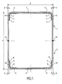
- a device element according to the invention is made by folding two sheets of constant thickness to give each folded part a channel 1 or 2 conformation, then by welding the two conformations 1 and 2 channel along two lines 3a, 3b assembly.
- the assembly thus formed forms a hollow box of substantially rectangular section of height h and width I, which has inclined faces 4a, 4b, 4c, 4d on both heights.
- the inclined faces 4a to 4d are inclined at the ends or vertices of the section and towards the inside of a value A of between three and ten degrees of angle, advantageously of the order of five degrees of angle.
- the conformations 1 and 2 channel are folded from sheets of the same thickness, but it is also possible to achieve a conformation in a thickness greater than the thickness of the other conformation, without departing from the scope of the This invention is interesting in particular for producing the foot element of a beam or telescopic arm.
- the height h of the device element sections according to the invention is increased relative to the prior art, while decreasing their average thickness, so as to reduce the mass of metal to be used for manufacturing a range. beams or telescopic arms.
- the increase in height h and the difference in thickness between conformations 1 and 2 make it possible in combination to reduce the number of elements in the complete range by approximately 40% and to reduce the tonnage of metal used by approximately 11%. .
- the difference in width between successive sliding elements is reduced thanks to the invention, by providing a placement of the sliding side skids on the inclined faces 4a to 4d, while maintaining the skids of sliding 6 in known manner under the upper and lower sides of a device element according to the invention.
- This arrangement makes it possible, on the one hand, to use a single type of sliding shoe of known type for each shoe 5 or 6.
- This arrangement allows, on the other hand, to use a common cage 7 for positioning and holding four pads 5 and 6 in the upper part and a common cage 8 for positioning and holding four pads 5 and 6 in the lower part.
- the increase in the height ha results in an increase in the spacing between the pads 5 and 6 of the upper part and the pads 5 and 6 of the lower part, which improves the torsional strength and the precision of the guiding of the end of the device according to the invention.
- a device according to the invention comprises an element 10 of larger section and a member 11 of smaller section mounted relative sliding with the interposition of pads 5 and 6 sliding.
- the element 10 comprises an end flange 12 provided with three threads 13a, 13b, 13c intended to receive screws 14 passing through the orifices of a counter flange 15 for holding two stands 16a, 16b for positioning and holding of pads 5 and 6.
- Each cage 16a or 16b comprises for this purpose a wing 17a or 17b provided with at least one orifice 18a or 18b of screw passage 14.
- each wing 17a or 17b is sandwiched between the flange 12 and the flange 15 and ensures the locking of the cage 16a or 16b corresponding.
- the lower flange of the flange 15 ensures the locking of the pads 5 and 6 inside their cage 16a or 16b during the relative sliding of the elements 10 and 11 in the extension direction of the telescope, while the bottom of the cages 16a or 16b ensures the locking of the pads 5 and 6 inside their cage 16a or 16b in the retraction direction of the telescope.
- Disassembly of the flange 15 also facilitates the replacement of worn pads 5 and 6 or the compensation of their wear by inserting a shim.
- the device according to the invention may also comprise at least one element 20 of even smaller section intended to be mounted relative sliding with the interposition of pads 5 and 6 sliding in the element 11 of smaller section.
- the element 20 comprises a jumper 22 forming an end flange and provided with two passages 23a and 23b intended to receive fastening screws with two stands 26a, 26b for positioning and holding pads 5 and 6.
- Each cage 26a or 26b is welded by a continuous bead 27a or 27b of welding to the main tube of the element 20 of even smaller section,
- Each cage 26a or 26b is provided with at least one tapping 28a or 28b for receiving a screw passing through one of the two passages 23a and 23b of the jumper 22 forming an end flange, thus ensuring the positioning and maintenance of the skids 5 and 6.
- the jumper 22 forming the end flange ensures the locking of the pads 5 and 6 inside their cage 26a or 26b during the relative sliding of the elements 20 and 11 in a first telescoping direction, while the bottom of the cages 26a or 26b ensures the blocking of the pads 5 and 6 inside their cage 26a or 26b in the opposite direction to this first telescoping direction.
- a device according to the invention comprises a sliding end element 20 and a mounting head 31 assembled by welding along a concave curve 32 of great length.
- the mounting head 31 is preferably a monoblock head made in one piece, for example by forging or by molding.
- the configuration of the mounting head 31 is determined in order to standardize the distribution of the stresses due to the loading and to clear the internal passages corresponding to the accommodation and to the displacement of the actuators such as tilt cylinder (s) or control rod (s) as well as than the protection of hoses and lines supplying hydraulic or electric power.
- the volume of the mounting head 31 is disengaged to ensure the operation of accessories and accessories to be mounted on the head 31.
- the concave weld curve 32 is made so as to position the sliding shoes 5 and 6 as far as possible from the sliding end element 20, avoiding the passage of the pads 5 and 6 on a weld bead. likely to wear them out or damage them.
- the sliding pads 5 and 6 positioned in front of the weld bead 32 are retained inside their cage by a rider 25 forming an end flange.
- the cord length of the concave continuous concave curve 32 is sufficient to distribute the stresses due to the loadings and to avoid any stress concentration: this length is preferably close to twice the section height of the terminal element 20.
- the decrease in mass and the increase in performance obtained by virtue of the invention make it possible to improve the performances and load charts of machines equipped with a device according to the invention.
Applications Claiming Priority (1)
| Application Number | Priority Date | Filing Date | Title |
|---|---|---|---|
| FR0700991A FR2912391B1 (fr) | 2007-02-12 | 2007-02-12 | "dispositif telescopique de manutention" |
Publications (2)
| Publication Number | Publication Date |
|---|---|
| EP1955975A1 true EP1955975A1 (de) | 2008-08-13 |
| EP1955975B1 EP1955975B1 (de) | 2011-08-31 |
Family
ID=38230054
Family Applications (1)
| Application Number | Title | Priority Date | Filing Date |
|---|---|---|---|
| EP08290044A Active EP1955975B1 (de) | 2007-02-12 | 2008-01-18 | Teleskopausleger |
Country Status (3)
| Country | Link |
|---|---|
| EP (1) | EP1955975B1 (de) |
| AT (1) | ATE522469T1 (de) |
| FR (1) | FR2912391B1 (de) |
Cited By (3)
| Publication number | Priority date | Publication date | Assignee | Title |
|---|---|---|---|---|
| US20120251284A1 (en) * | 2011-03-30 | 2012-10-04 | Genie Industries, Inc. | Wearpad arrangement |
| US20160039650A1 (en) * | 2014-08-07 | 2016-02-11 | Manitou Bf | Telescopic handling device comprising at least two elements mounted so as to slide relative to one another |
| CN111498758A (zh) * | 2020-04-09 | 2020-08-07 | 中联重科股份有限公司 | U型臂架组件、u型臂和高空作业设备 |
Citations (9)
| Publication number | Priority date | Publication date | Assignee | Title |
|---|---|---|---|---|
| DE1945134A1 (de) * | 1969-09-05 | 1971-04-08 | Demag Baumaschinen Gmbh | Teleskopausleger fuer Krane od.dgl. |
| DE2009298A1 (de) * | 1969-10-30 | 1971-05-06 | Institut fur Fordertechnik Leipzig, χ 7034 Leipzig | Fuhrung fur teleskopierbare Ausleger |
| DE2303644A1 (de) * | 1973-01-25 | 1974-11-07 | Kaessbohrer Fahrzeug Karl | Teleskopausleger fuer krane |
| DE29715843U1 (de) * | 1997-09-03 | 1997-11-13 | Bison Stematec Maschinenbau Un | Selbsttätig angleichende Teleskopgleitlagerung |
| DE29804237U1 (de) * | 1998-03-10 | 1998-05-07 | Liebherr Werk Ehingen | Gleitlager für ineinandergelagerte schalenförmige Körper |
| FR2759687A1 (fr) * | 1997-02-14 | 1998-08-21 | Fdi Sambron | Patin de guidage pour fleche telescopique et fleche telescopique pourvue d'un tel guidade |
| FR2790538A1 (fr) | 1999-03-02 | 2000-09-08 | Ppm | Structure de poutre en caisson creux, poutre en faisant application et fleche telescopique la mettant en oeuvre |
| EP1090875A1 (de) | 1999-10-06 | 2001-04-11 | Atecs Mannesmann AG | Teleskopsausleger für Krane |
| EP1281658A1 (de) | 2001-08-03 | 2003-02-05 | Mannesmannröhren-Werke AG | Verwendung eines langgestreckten warmgefertigten Hohlprofiles für einen teleskopierbaren Ausleger einer Hubeinrichtung |
-
2007
- 2007-02-12 FR FR0700991A patent/FR2912391B1/fr active Active
-
2008
- 2008-01-18 AT AT08290044T patent/ATE522469T1/de not_active IP Right Cessation
- 2008-01-18 EP EP08290044A patent/EP1955975B1/de active Active
Patent Citations (9)
| Publication number | Priority date | Publication date | Assignee | Title |
|---|---|---|---|---|
| DE1945134A1 (de) * | 1969-09-05 | 1971-04-08 | Demag Baumaschinen Gmbh | Teleskopausleger fuer Krane od.dgl. |
| DE2009298A1 (de) * | 1969-10-30 | 1971-05-06 | Institut fur Fordertechnik Leipzig, χ 7034 Leipzig | Fuhrung fur teleskopierbare Ausleger |
| DE2303644A1 (de) * | 1973-01-25 | 1974-11-07 | Kaessbohrer Fahrzeug Karl | Teleskopausleger fuer krane |
| FR2759687A1 (fr) * | 1997-02-14 | 1998-08-21 | Fdi Sambron | Patin de guidage pour fleche telescopique et fleche telescopique pourvue d'un tel guidade |
| DE29715843U1 (de) * | 1997-09-03 | 1997-11-13 | Bison Stematec Maschinenbau Un | Selbsttätig angleichende Teleskopgleitlagerung |
| DE29804237U1 (de) * | 1998-03-10 | 1998-05-07 | Liebherr Werk Ehingen | Gleitlager für ineinandergelagerte schalenförmige Körper |
| FR2790538A1 (fr) | 1999-03-02 | 2000-09-08 | Ppm | Structure de poutre en caisson creux, poutre en faisant application et fleche telescopique la mettant en oeuvre |
| EP1090875A1 (de) | 1999-10-06 | 2001-04-11 | Atecs Mannesmann AG | Teleskopsausleger für Krane |
| EP1281658A1 (de) | 2001-08-03 | 2003-02-05 | Mannesmannröhren-Werke AG | Verwendung eines langgestreckten warmgefertigten Hohlprofiles für einen teleskopierbaren Ausleger einer Hubeinrichtung |
Cited By (7)
| Publication number | Priority date | Publication date | Assignee | Title |
|---|---|---|---|---|
| US20120251284A1 (en) * | 2011-03-30 | 2012-10-04 | Genie Industries, Inc. | Wearpad arrangement |
| US8801354B2 (en) * | 2011-03-30 | 2014-08-12 | Terex South Dakota, Inc. | Wearpad arrangement |
| EP2691581A4 (de) * | 2011-03-30 | 2015-05-20 | Terex South Dakota Inc | Verschleissschutzanordnung |
| AU2012236929B2 (en) * | 2011-03-30 | 2016-08-04 | Terex South Dakota, Inc. | Wearpad arrangement |
| US20160039650A1 (en) * | 2014-08-07 | 2016-02-11 | Manitou Bf | Telescopic handling device comprising at least two elements mounted so as to slide relative to one another |
| US9938124B2 (en) * | 2014-08-07 | 2018-04-10 | Manitou Bf | Telescopic handling device comprising at least two elements mounted so as to slide relative to one another |
| CN111498758A (zh) * | 2020-04-09 | 2020-08-07 | 中联重科股份有限公司 | U型臂架组件、u型臂和高空作业设备 |
Also Published As
| Publication number | Publication date |
|---|---|
| EP1955975B1 (de) | 2011-08-31 |
| FR2912391A1 (fr) | 2008-08-15 |
| FR2912391B1 (fr) | 2009-12-25 |
| ATE522469T1 (de) | 2011-09-15 |
Similar Documents
| Publication | Publication Date | Title |
|---|---|---|
| EP2486247B1 (de) | Vorrichtung zur zentrierung und führung der rotation einer turbomaschinenachse | |
| EP2366060B1 (de) | Gebläse für ein Turbotriebwerk mit einem Auswuchtsystem mit Blindlöchern zur Unterbringung von Gewichten und zugehöriges Turbotriebwerk | |
| EP2598722B1 (de) | Vorrichtung zur steuerung der schwenkbaren schaufeln eines turbinenmotors | |
| FR3017163A1 (fr) | Dispositif pour une helice non carenee a pales a calage variable d'une turbomachine | |
| EP3472479B1 (de) | Längenverstellbare pleuelstange für eine turbomaschine | |
| WO2013128123A1 (fr) | Procede pour maintenir une piece d'adaptation sur un carter tubulaire d'un turbomoteur, piece d'adaptation et systeme de maintien correspondants | |
| FR2984845A1 (fr) | Element de structure de fuselage d'aeronef anti deversement | |
| EP1955975B1 (de) | Teleskopausleger | |
| EP2052449A2 (de) | Träger zur anbringung von elektrokabeln an einer struktur | |
| EP3084140B1 (de) | Führungsarm für gegenstände mit länglicher form, insbesondere für eine turbomaschine | |
| WO2015110749A1 (fr) | Carter de turbomachine à virole sans empochements et à chapes renforcées par des raidisseurs | |
| EP3074596B1 (de) | Ausgewuchtetes gasturbinenmotorteil und zugehöriges verfahren | |
| EP2058477A1 (de) | Verbindung von radialen Streben mit einem kreisförmigen Gehäuse durch Stifte und Abstandshalter | |
| EP1939409A1 (de) | System zur Verbindung von zwei in etwa röhrenförmigen Elementen, Gehäuse, das ein solches System umfasst, und Verwendung dieses Systems | |
| EP2855876B1 (de) | Verfahren zur verbesserten montage eines aktuators für ein luftauslassventil eines turbinenmotors | |
| EP2435686B1 (de) | Teil zur Zusammenfügung des beweglichen Teils einer einsetzbaren divergierenden Düse einer Antriebseinheit und Mechanismus für den Einsatz des beweglichen Teils | |
| EP3999789B1 (de) | Zuganker, insbesondere für eine gitterstruktur | |
| EP3708877B1 (de) | Planetengetriebe, leistungsübertragungsgetriebe, luftfahrzeug und verfahren | |
| CA3116776C (fr) | Troncon de mat d'eolienne, mat d'eolienne et procede d'assemblage | |
| EP2702208B1 (de) | Schleusentor | |
| EP3842597B1 (de) | Gelenkverbindungssystem für tragende elemente | |
| BE1028105B1 (fr) | Système de connexion articulé pour éléments portants | |
| EP2892806B1 (de) | Hilfsantriebsgetriebe zur steuerung der auftriebsklappen eines flugzeugs | |
| EP1953318A1 (de) | Ausgleichssystem einer Klappe | |
| FR3018097B1 (fr) | Organe de turbomachine comportant une piece metallique et une piece en materiau composite |
Legal Events
| Date | Code | Title | Description |
|---|---|---|---|
| PUAI | Public reference made under article 153(3) epc to a published international application that has entered the european phase |
Free format text: ORIGINAL CODE: 0009012 |
|
| AK | Designated contracting states |
Kind code of ref document: A1 Designated state(s): AT BE BG CH CY CZ DE DK EE ES FI FR GB GR HR HU IE IS IT LI LT LU LV MC MT NL NO PL PT RO SE SI SK TR |
|
| AX | Request for extension of the european patent |
Extension state: AL BA MK RS |
|
| 17P | Request for examination filed |
Effective date: 20090204 |
|
| AKX | Designation fees paid |
Designated state(s): AT BE BG CH CY CZ DE DK EE ES FI FR GB GR HR HU IE IS IT LI LT LU LV MC MT NL NO PL PT RO SE SI SK TR |
|
| GRAP | Despatch of communication of intention to grant a patent |
Free format text: ORIGINAL CODE: EPIDOSNIGR1 |
|
| GRAS | Grant fee paid |
Free format text: ORIGINAL CODE: EPIDOSNIGR3 |
|
| GRAA | (expected) grant |
Free format text: ORIGINAL CODE: 0009210 |
|
| AK | Designated contracting states |
Kind code of ref document: B1 Designated state(s): AT BE BG CH CY CZ DE DK EE ES FI FR GB GR HR HU IE IS IT LI LT LU LV MC MT NL NO PL PT RO SE SI SK TR |
|
| REG | Reference to a national code |
Ref country code: GB Ref legal event code: FG4D Free format text: NOT ENGLISH Ref country code: CH Ref legal event code: EP |
|
| REG | Reference to a national code |
Ref country code: IE Ref legal event code: FG4D Free format text: LANGUAGE OF EP DOCUMENT: FRENCH |
|
| REG | Reference to a national code |
Ref country code: DE Ref legal event code: R096 Ref document number: 602008009280 Country of ref document: DE Effective date: 20111103 |
|
| REG | Reference to a national code |
Ref country code: NL Ref legal event code: T3 |
|
| LTIE | Lt: invalidation of european patent or patent extension |
Effective date: 20110831 |
|
| PG25 | Lapsed in a contracting state [announced via postgrant information from national office to epo] |
Ref country code: FI Free format text: LAPSE BECAUSE OF FAILURE TO SUBMIT A TRANSLATION OF THE DESCRIPTION OR TO PAY THE FEE WITHIN THE PRESCRIBED TIME-LIMIT Effective date: 20110831 Ref country code: IS Free format text: LAPSE BECAUSE OF FAILURE TO SUBMIT A TRANSLATION OF THE DESCRIPTION OR TO PAY THE FEE WITHIN THE PRESCRIBED TIME-LIMIT Effective date: 20111231 Ref country code: LT Free format text: LAPSE BECAUSE OF FAILURE TO SUBMIT A TRANSLATION OF THE DESCRIPTION OR TO PAY THE FEE WITHIN THE PRESCRIBED TIME-LIMIT Effective date: 20110831 Ref country code: HR Free format text: LAPSE BECAUSE OF FAILURE TO SUBMIT A TRANSLATION OF THE DESCRIPTION OR TO PAY THE FEE WITHIN THE PRESCRIBED TIME-LIMIT Effective date: 20110831 Ref country code: NO Free format text: LAPSE BECAUSE OF FAILURE TO SUBMIT A TRANSLATION OF THE DESCRIPTION OR TO PAY THE FEE WITHIN THE PRESCRIBED TIME-LIMIT Effective date: 20111130 Ref country code: SE Free format text: LAPSE BECAUSE OF FAILURE TO SUBMIT A TRANSLATION OF THE DESCRIPTION OR TO PAY THE FEE WITHIN THE PRESCRIBED TIME-LIMIT Effective date: 20110831 |
|
| REG | Reference to a national code |
Ref country code: AT Ref legal event code: MK05 Ref document number: 522469 Country of ref document: AT Kind code of ref document: T Effective date: 20110831 |
|
| PG25 | Lapsed in a contracting state [announced via postgrant information from national office to epo] |
Ref country code: AT Free format text: LAPSE BECAUSE OF FAILURE TO SUBMIT A TRANSLATION OF THE DESCRIPTION OR TO PAY THE FEE WITHIN THE PRESCRIBED TIME-LIMIT Effective date: 20110831 Ref country code: CY Free format text: LAPSE BECAUSE OF FAILURE TO SUBMIT A TRANSLATION OF THE DESCRIPTION OR TO PAY THE FEE WITHIN THE PRESCRIBED TIME-LIMIT Effective date: 20110831 Ref country code: GR Free format text: LAPSE BECAUSE OF FAILURE TO SUBMIT A TRANSLATION OF THE DESCRIPTION OR TO PAY THE FEE WITHIN THE PRESCRIBED TIME-LIMIT Effective date: 20111201 Ref country code: SI Free format text: LAPSE BECAUSE OF FAILURE TO SUBMIT A TRANSLATION OF THE DESCRIPTION OR TO PAY THE FEE WITHIN THE PRESCRIBED TIME-LIMIT Effective date: 20110831 Ref country code: LV Free format text: LAPSE BECAUSE OF FAILURE TO SUBMIT A TRANSLATION OF THE DESCRIPTION OR TO PAY THE FEE WITHIN THE PRESCRIBED TIME-LIMIT Effective date: 20110831 |
|
| REG | Reference to a national code |
Ref country code: IE Ref legal event code: FD4D |
|
| PG25 | Lapsed in a contracting state [announced via postgrant information from national office to epo] |
Ref country code: SK Free format text: LAPSE BECAUSE OF FAILURE TO SUBMIT A TRANSLATION OF THE DESCRIPTION OR TO PAY THE FEE WITHIN THE PRESCRIBED TIME-LIMIT Effective date: 20110831 Ref country code: CZ Free format text: LAPSE BECAUSE OF FAILURE TO SUBMIT A TRANSLATION OF THE DESCRIPTION OR TO PAY THE FEE WITHIN THE PRESCRIBED TIME-LIMIT Effective date: 20110831 Ref country code: IE Free format text: LAPSE BECAUSE OF FAILURE TO SUBMIT A TRANSLATION OF THE DESCRIPTION OR TO PAY THE FEE WITHIN THE PRESCRIBED TIME-LIMIT Effective date: 20110831 |
|
| PG25 | Lapsed in a contracting state [announced via postgrant information from national office to epo] |
Ref country code: RO Free format text: LAPSE BECAUSE OF FAILURE TO SUBMIT A TRANSLATION OF THE DESCRIPTION OR TO PAY THE FEE WITHIN THE PRESCRIBED TIME-LIMIT Effective date: 20110831 Ref country code: PL Free format text: LAPSE BECAUSE OF FAILURE TO SUBMIT A TRANSLATION OF THE DESCRIPTION OR TO PAY THE FEE WITHIN THE PRESCRIBED TIME-LIMIT Effective date: 20110831 Ref country code: EE Free format text: LAPSE BECAUSE OF FAILURE TO SUBMIT A TRANSLATION OF THE DESCRIPTION OR TO PAY THE FEE WITHIN THE PRESCRIBED TIME-LIMIT Effective date: 20110831 Ref country code: PT Free format text: LAPSE BECAUSE OF FAILURE TO SUBMIT A TRANSLATION OF THE DESCRIPTION OR TO PAY THE FEE WITHIN THE PRESCRIBED TIME-LIMIT Effective date: 20120102 |
|
| PG25 | Lapsed in a contracting state [announced via postgrant information from national office to epo] |
Ref country code: DK Free format text: LAPSE BECAUSE OF FAILURE TO SUBMIT A TRANSLATION OF THE DESCRIPTION OR TO PAY THE FEE WITHIN THE PRESCRIBED TIME-LIMIT Effective date: 20110831 |
|
| PLBE | No opposition filed within time limit |
Free format text: ORIGINAL CODE: 0009261 |
|
| STAA | Information on the status of an ep patent application or granted ep patent |
Free format text: STATUS: NO OPPOSITION FILED WITHIN TIME LIMIT |
|
| BERE | Be: lapsed |
Owner name: MANITOU BF Effective date: 20120131 |
|
| 26N | No opposition filed |
Effective date: 20120601 |
|
| PG25 | Lapsed in a contracting state [announced via postgrant information from national office to epo] |
Ref country code: MC Free format text: LAPSE BECAUSE OF NON-PAYMENT OF DUE FEES Effective date: 20120131 |
|
| REG | Reference to a national code |
Ref country code: CH Ref legal event code: PL |
|
| REG | Reference to a national code |
Ref country code: DE Ref legal event code: R097 Ref document number: 602008009280 Country of ref document: DE Effective date: 20120601 |
|
| PG25 | Lapsed in a contracting state [announced via postgrant information from national office to epo] |
Ref country code: CH Free format text: LAPSE BECAUSE OF NON-PAYMENT OF DUE FEES Effective date: 20120131 Ref country code: LI Free format text: LAPSE BECAUSE OF NON-PAYMENT OF DUE FEES Effective date: 20120131 |
|
| PG25 | Lapsed in a contracting state [announced via postgrant information from national office to epo] |
Ref country code: BE Free format text: LAPSE BECAUSE OF NON-PAYMENT OF DUE FEES Effective date: 20120131 |
|
| PG25 | Lapsed in a contracting state [announced via postgrant information from national office to epo] |
Ref country code: ES Free format text: LAPSE BECAUSE OF FAILURE TO SUBMIT A TRANSLATION OF THE DESCRIPTION OR TO PAY THE FEE WITHIN THE PRESCRIBED TIME-LIMIT Effective date: 20111211 |
|
| PG25 | Lapsed in a contracting state [announced via postgrant information from national office to epo] |
Ref country code: BG Free format text: LAPSE BECAUSE OF FAILURE TO SUBMIT A TRANSLATION OF THE DESCRIPTION OR TO PAY THE FEE WITHIN THE PRESCRIBED TIME-LIMIT Effective date: 20111130 |
|
| PG25 | Lapsed in a contracting state [announced via postgrant information from national office to epo] |
Ref country code: MT Free format text: LAPSE BECAUSE OF FAILURE TO SUBMIT A TRANSLATION OF THE DESCRIPTION OR TO PAY THE FEE WITHIN THE PRESCRIBED TIME-LIMIT Effective date: 20110831 |
|
| PG25 | Lapsed in a contracting state [announced via postgrant information from national office to epo] |
Ref country code: TR Free format text: LAPSE BECAUSE OF FAILURE TO SUBMIT A TRANSLATION OF THE DESCRIPTION OR TO PAY THE FEE WITHIN THE PRESCRIBED TIME-LIMIT Effective date: 20110831 |
|
| PG25 | Lapsed in a contracting state [announced via postgrant information from national office to epo] |
Ref country code: LU Free format text: LAPSE BECAUSE OF NON-PAYMENT OF DUE FEES Effective date: 20120118 |
|
| PG25 | Lapsed in a contracting state [announced via postgrant information from national office to epo] |
Ref country code: HU Free format text: LAPSE BECAUSE OF FAILURE TO SUBMIT A TRANSLATION OF THE DESCRIPTION OR TO PAY THE FEE WITHIN THE PRESCRIBED TIME-LIMIT Effective date: 20080118 |
|
| REG | Reference to a national code |
Ref country code: DE Ref legal event code: R082 Ref document number: 602008009280 Country of ref document: DE Representative=s name: PATENTANWAELTE LIPPERT, STACHOW & PARTNER, DE Ref country code: DE Ref legal event code: R082 Ref document number: 602008009280 Country of ref document: DE Representative=s name: LIPPERT STACHOW PATENTANWAELTE RECHTSANWAELTE , DE |
|
| REG | Reference to a national code |
Ref country code: FR Ref legal event code: PLFP Year of fee payment: 9 |
|
| REG | Reference to a national code |
Ref country code: FR Ref legal event code: PLFP Year of fee payment: 10 |
|
| REG | Reference to a national code |
Ref country code: FR Ref legal event code: PLFP Year of fee payment: 11 |
|
| PGFP | Annual fee paid to national office [announced via postgrant information from national office to epo] |
Ref country code: FR Payment date: 20230124 Year of fee payment: 16 |
|
| PGFP | Annual fee paid to national office [announced via postgrant information from national office to epo] |
Ref country code: IT Payment date: 20230120 Year of fee payment: 16 |
|
| P01 | Opt-out of the competence of the unified patent court (upc) registered |
Effective date: 20230621 |
|
| PGFP | Annual fee paid to national office [announced via postgrant information from national office to epo] |
Ref country code: NL Payment date: 20240119 Year of fee payment: 17 |
|
| PGFP | Annual fee paid to national office [announced via postgrant information from national office to epo] |
Ref country code: DE Payment date: 20240119 Year of fee payment: 17 Ref country code: GB Payment date: 20240119 Year of fee payment: 17 |