EP1955942A2 - Bicycle brake and shift operating device - Google Patents
Bicycle brake and shift operating device Download PDFInfo
- Publication number
- EP1955942A2 EP1955942A2 EP07022622A EP07022622A EP1955942A2 EP 1955942 A2 EP1955942 A2 EP 1955942A2 EP 07022622 A EP07022622 A EP 07022622A EP 07022622 A EP07022622 A EP 07022622A EP 1955942 A2 EP1955942 A2 EP 1955942A2
- Authority
- EP
- European Patent Office
- Prior art keywords
- shift operating
- operating member
- shift
- brake
- brake lever
- Prior art date
- Legal status (The legal status is an assumption and is not a legal conclusion. Google has not performed a legal analysis and makes no representation as to the accuracy of the status listed.)
- Granted
Links
- 230000008878 coupling Effects 0.000 description 7
- 238000010168 coupling process Methods 0.000 description 7
- 238000005859 coupling reaction Methods 0.000 description 7
- 210000003811 finger Anatomy 0.000 description 5
- 230000005540 biological transmission Effects 0.000 description 4
- 230000006870 function Effects 0.000 description 4
- 230000007246 mechanism Effects 0.000 description 4
- 238000005452 bending Methods 0.000 description 3
- 230000007935 neutral effect Effects 0.000 description 3
- 230000009467 reduction Effects 0.000 description 2
- 230000004044 response Effects 0.000 description 2
- 230000035807 sensation Effects 0.000 description 2
- 230000008859 change Effects 0.000 description 1
- 238000010586 diagram Methods 0.000 description 1
- 210000004905 finger nail Anatomy 0.000 description 1
- 230000004048 modification Effects 0.000 description 1
- 238000012986 modification Methods 0.000 description 1
- 238000007789 sealing Methods 0.000 description 1
- 230000009192 sprinting Effects 0.000 description 1
- 210000003813 thumb Anatomy 0.000 description 1
- 238000004078 waterproofing Methods 0.000 description 1
Images


Classifications
-
- B—PERFORMING OPERATIONS; TRANSPORTING
- B60—VEHICLES IN GENERAL
- B60K—ARRANGEMENT OR MOUNTING OF PROPULSION UNITS OR OF TRANSMISSIONS IN VEHICLES; ARRANGEMENT OR MOUNTING OF PLURAL DIVERSE PRIME-MOVERS IN VEHICLES; AUXILIARY DRIVES FOR VEHICLES; INSTRUMENTATION OR DASHBOARDS FOR VEHICLES; ARRANGEMENTS IN CONNECTION WITH COOLING, AIR INTAKE, GAS EXHAUST OR FUEL SUPPLY OF PROPULSION UNITS IN VEHICLES
- B60K23/00—Arrangement or mounting of control devices for vehicle transmissions, or parts thereof, not otherwise provided for
- B60K23/06—Arrangement or mounting of control devices for vehicle transmissions, or parts thereof, not otherwise provided for for freewheel devices
-
- B—PERFORMING OPERATIONS; TRANSPORTING
- B62—LAND VEHICLES FOR TRAVELLING OTHERWISE THAN ON RAILS
- B62K—CYCLES; CYCLE FRAMES; CYCLE STEERING DEVICES; RIDER-OPERATED TERMINAL CONTROLS SPECIALLY ADAPTED FOR CYCLES; CYCLE AXLE SUSPENSIONS; CYCLE SIDE-CARS, FORECARS, OR THE LIKE
- B62K23/00—Rider-operated controls specially adapted for cycles, i.e. means for initiating control operations, e.g. levers, grips
- B62K23/02—Rider-operated controls specially adapted for cycles, i.e. means for initiating control operations, e.g. levers, grips hand actuated
- B62K23/06—Levers
-
- B—PERFORMING OPERATIONS; TRANSPORTING
- B62—LAND VEHICLES FOR TRAVELLING OTHERWISE THAN ON RAILS
- B62L—BRAKES SPECIALLY ADAPTED FOR CYCLES
- B62L3/00—Brake-actuating mechanisms; Arrangements thereof
- B62L3/02—Brake-actuating mechanisms; Arrangements thereof for control by a hand lever
- B62L3/026—Brake-actuating mechanisms; Arrangements thereof for control by a hand lever actuation by a turning handle or handlebar
-
- B—PERFORMING OPERATIONS; TRANSPORTING
- B62—LAND VEHICLES FOR TRAVELLING OTHERWISE THAN ON RAILS
- B62M—RIDER PROPULSION OF WHEELED VEHICLES OR SLEDGES; POWERED PROPULSION OF SLEDGES OR SINGLE-TRACK CYCLES; TRANSMISSIONS SPECIALLY ADAPTED FOR SUCH VEHICLES
- B62M25/00—Actuators for gearing speed-change mechanisms specially adapted for cycles
- B62M25/02—Actuators for gearing speed-change mechanisms specially adapted for cycles with mechanical transmitting systems, e.g. cables, levers
- B62M25/04—Actuators for gearing speed-change mechanisms specially adapted for cycles with mechanical transmitting systems, e.g. cables, levers hand actuated
-
- Y—GENERAL TAGGING OF NEW TECHNOLOGICAL DEVELOPMENTS; GENERAL TAGGING OF CROSS-SECTIONAL TECHNOLOGIES SPANNING OVER SEVERAL SECTIONS OF THE IPC; TECHNICAL SUBJECTS COVERED BY FORMER USPC CROSS-REFERENCE ART COLLECTIONS [XRACs] AND DIGESTS
- Y10—TECHNICAL SUBJECTS COVERED BY FORMER USPC
- Y10T—TECHNICAL SUBJECTS COVERED BY FORMER US CLASSIFICATION
- Y10T74/00—Machine element or mechanism
- Y10T74/20—Control lever and linkage systems
- Y10T74/20207—Multiple controlling elements for single controlled element
- Y10T74/20256—Steering and controls assemblies
- Y10T74/20268—Reciprocating control elements
- Y10T74/2028—Handle bar type
- Y10T74/20287—Flexible control element
-
- Y—GENERAL TAGGING OF NEW TECHNOLOGICAL DEVELOPMENTS; GENERAL TAGGING OF CROSS-SECTIONAL TECHNOLOGIES SPANNING OVER SEVERAL SECTIONS OF THE IPC; TECHNICAL SUBJECTS COVERED BY FORMER USPC CROSS-REFERENCE ART COLLECTIONS [XRACs] AND DIGESTS
- Y10—TECHNICAL SUBJECTS COVERED BY FORMER USPC
- Y10T—TECHNICAL SUBJECTS COVERED BY FORMER US CLASSIFICATION
- Y10T74/00—Machine element or mechanism
- Y10T74/20—Control lever and linkage systems
- Y10T74/20396—Hand operated
- Y10T74/20402—Flexible transmitter [e.g., Bowden cable]
- Y10T74/2042—Flexible transmitter [e.g., Bowden cable] and hand operator
- Y10T74/20438—Single rotatable lever [e.g., for bicycle brake or derailleur]
Definitions
- a known shift operating device of this type is shown in U.S. Patent No. 6,991,081 .
- That shift operating device includes shift operating members and electric switches mounted to a brake bracket and to a brake lever of a brake operating device.
- One shift operating member is used to control the operation of an electrically operated front derailleur
- another shift operating member is used to control the operation of an electrically operated rear derailleur.
- the shift operating device for the rear derailleur is disposed on the right side of the handlebar
- the shift operating device for the front derailleur is disposed on the left side of the handle bar in the same manner as conventional cable-operated shift operating devices.
- Fig. 7 is a left side view of the brake and shift operating device shown in Fig. 2 ;
- a rear shift operating unit 34r used exclusively for upshifting rear derailleur 97r is mounted on a lower portion of curved portion 112a of handlebar 112.
- Rear shift operating unit 34r enables easy upshifting when the rider grips an end portion 112c of handle bar 112 instead of curved portion 112a (e.g., during sprinting).
- Rear shift operating unit 34r comprises a lever-type switch unit that pivots outward relative to handlebar 112 as shown by arrow B in Fig. 4 , thereby making it easy to operate the lever with the thumb.
- Pivot shaft 58 comprises a head portion 58a disposed at the rear end of pivot shaft 58, a screw portion 58b disposed at the front of pivot shaft 58, and a shaft portion 58c disposed between head portion 58a and screw portion 58b.
- Shaft portion 58c has a diameter that is larger than screw portion 58b.
- Second shift operating member 44r is a generally plate-shaped member used for downshifting rear derailleur 97r. Second shift operating member 44r also pivots from an operation starting (home) position inwardly towards the center of handlebar 112 as indicated by arrow A in Fig. 4 . Second shift operating member 44r comprises an upper second supported portion 65 with a second support hole 65a through which pivot shaft 58 passes, a second arm portion 66 extending radially downwardly from second supported portion 65, and a second operating portion 67 that bends approximately 90 degrees from the bottom of second arm portion 66. Second arm portion 66 bends backwards and then downwards in the midsection thereof.
- Second operating portion 67 is obliquely disposed with a tip thereof slightly bent to be disposed parallel to and aligned with first operating portion 62.
- a generally plane-shaped second operating surface 67a is formed on the exterior surface of second operating portion 67.
- second operating portion 67 is disposed at a position that is further away from pivot shaft 58 than first operating portion 62. More specifically, second operating portion 67 is disposed at a different radial position from first operating portion 62 relative to pivot shaft 58.
- first and second shift operating members 42r and 44r are at their respective home positions, first operating surface 63a and second operating surface 67a are disposed on different planes.
- a biasing member in the form of a coil spring 77 is disposed coaxially around each coil spring 75 between switch bracket 70 and the corresponding first shift operating member 42r or second shift operating member 44r for biasing the first switch operating member 42r or second switch operating member 44r to their respective home positions.
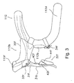
- brake and shift operating device 110b has a configuration that is essentially a mirror image of brake and shift operating device 110a. As shown in Figs. 3 and 5 , brake and shift operating device 110b comprises a brake bracket 30f, a brake lever 31f pivotably connected to brake bracket 30f through a pivot shaft 33f for operating front brake device 107f, and a front shift operating unit 32f for operating front derailleur 97f.
- front shift operating unit 32f comprises a mounting member 40f mounted to a rear surface of a lever operating portion 31b of brake lever 31f, a first shift operating member 42f movably coupled to brake lever 31r through mounting member 40f, a separate second shift operating member 44f movably coupled to brake lever 31f through mounting member 40f, a first electric switch 46f ( Fig. 10 ) operated by first shift operating member 42f, and a second electric switch 48f ( Fig. 10 ) operated by second shift operating member 44f. Since both first shift operating member 42f and second shift operating member 44f move laterally inwardly, both upshifting and downshifting of front derailleur 97f may be performed very comfortably.
- brake and shift operating device 110a and shift operating unit 34r are connected by electric wiring through connector 118 to electric drive unit 18r of rear derailleur 97r
- brake and shift operating device 110b and shift operating unit 34f are connected by electric wiring through connector 118 to electric drive unit 18f of front derailleur 97f
- Power supply 20 mounted to front derailleur 97f provides a direct-current power supply voltage V of approximately 6 to 8.4 volts to electric drive unit 18f through a power wire 150 and a ground wire 151.
- the power supply voltage V also is communicated from electric drive unit 18f to electric drive unit 18r through a power wire 152 and a ground wire 153.
- Power wire 152 and ground wire 153 are connected to connector 118 to provide operating power to brake and shift operating devices 110a and 110b and to front and rear gear shift display devices 119f and 119r.
Abstract
Description
- The present invention is directed to bicycle brake and shift operating devices and, more particularly, to a bicycle brake and shift operating device that is mountable on a handlebar of a bicycle for controlling the operation of a brake device and an electrically operated bicycle transmission.
- Many current bicycle shift operating devices have the ability to electrically control the shifting of a bicycle transmission through a plurality of gear ratios. A known shift operating device of this type is shown in
U.S. Patent No. 6,991,081 . That shift operating device includes shift operating members and electric switches mounted to a brake bracket and to a brake lever of a brake operating device. One shift operating member is used to control the operation of an electrically operated front derailleur, and another shift operating member is used to control the operation of an electrically operated rear derailleur. The shift operating device for the rear derailleur is disposed on the right side of the handlebar, and the shift operating device for the front derailleur is disposed on the left side of the handle bar in the same manner as conventional cable-operated shift operating devices. Each shift operating device comprises a shift switch including a lever member that pivots laterally in opposite directions from a neutral starting position. Pivoting the lever member in one direction from the neutral position produces electrical signals to upshift the bicycle transmission by one gear, and pivoting the lever member in the opposite direction from the neutral position produces electrical signals to downshift the bicycle transmission by one gear. - The lever member normally is pivoted by using one or more fingers of the rider's hand while simultaneously grasping the handlebar or the brake lever mounting bracket. Pivoting the lever member laterally inwardly towards the center of the handlebar is easy because it follows the natural bending of the fingers when the hand is grasping the handlebar. However, pivoting the lever member laterally outwardly is more difficult because it requires using a dorsal part of the finger such as the fingernail and hyperextending the finger in a manner that tends to loosen the rider's grip on the handlebar.
- The present invention is directed to various features of a bicycle brake and shift operating device. In one embodiment, a bicycle brake and shifting device comprises a mounting bracket structured to be mounted on a bicycle handlebar; a brake lever pivotably coupled to the brake bracket; a first shift operating member movably coupled to the brake lever; a second shift operating member movably coupled to the brake lever, wherein the second shift operating member is a separate member from the first shift operating member; a first electric switch operated by the first shift operating member; and a second electric switch operated by the second shift operating member. Additional inventive features will become apparent from the description below, and such features alone or in combination with the above features and their equivalents may form the basis of further inventions as recited in the claims.
-
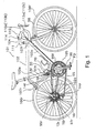
Fig. 1 is a side view of a bicycle that employs embodiments of brake and shift operating devices; -
Fig. 2 is an enlarged side view of a brake and shift operating device for operating a rear brake and derailleur of the bicycle; -
Fig. 3 is an enlarged side view of a brake and shift operating device for operating a front brake and derailleur of the bicycle; -
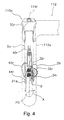
Fig. 4 is a front view of the brake and shift operating device shown inFig. 2 ; -
Fig. 5 is an enlarged plan view of the upper portions of the brake and shift operating devices; -
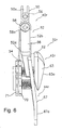
Fig. 6 is a rear view of the brake and shift operating device shown inFig. 2 ; -
Fig. 7 is a left side view of the brake and shift operating device shown inFig. 2 ; -
Fig. 8 is a right side view of the brake and shift operating device shown inFig. 2 ; -
Fig. 9 is a perspective cross-sectional view of a switch unit; and -
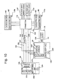
Fig. 10 is a schematic diagram of a shift control system. -
Fig. 1 is a side view of a particular embodiment of abicycle 101.Bicycle 101 is a road bicycle comprising a diamond-shaped frame 102, afront fork 98 rotatably mounted toframe 102, ahandlebar assembly 104 mounted to the upper part offork 98, afront wheel 106f rotatably attached to the lower part offork 98, arear wheel 106r rotatably attached to the rear offrame 102, and adrive unit 105. Afront wheel brake 107f is provided for brakingfront wheel 106f, and arear wheel brake 107r is provided for brakingrear wheel 106r. -
Drive unit 105 comprises achain 95, afront sprocket assembly 99f coaxially mounted with acrank 96 having pedals PD, an electrically operatedfront derailleur 97f attached to aseat tube 102a offrame 102, a rear sprocket assembly 99r coaxially mounted withrear wheel 106r, and an electrically operatedrear derailleur 97r. In this embodiment,front sprocket assembly 99f comprises two sprockets mounted coaxially withcrank 96, and rear sprocket assembly 99r comprises ten sprockets mounted coaxially withrear wheel 106r. The smallest front sprocket and the largest rear sprocket are located closest toframe 102 in a well-known manner.Front derailleur 97f moves to two operating positions to switchchain 95 between the two front sprockets, andrear derailleur 97r moves to ten operating positions to switchchain 95 among selected ones of the ten rear sprockets. -
Handlebar assembly 104 comprises ahandlebar stem 111 and a drop-style handlebar 112, whereinhandlebar stem 111 is mounted to the upper part offork 98, andhandlebar 112 is mounted to the forward end portion ofhandlebar stem 111. Handlebar 112 includes a right-side, forwardly bending U-shapedcurved portion 112a and a left-side, forwardly bending U-shapedcurved portion 112b. A brake andshift operating device 110a for controlling the operation ofrear brake 107r andrear derailleur 97r is mounted tocurved portion 112a as shown inFig. 2 , and a brake andshift operating device 110b for controlling the operation offront brake 107f andfront derailleur 97f is mounted tocurved portion 112b as shown inFig. 3 . As used herein, the terms up, down, front and rear refer to the orientation of an upstanding bicycle as shown inFig. 1 , wherein the front of the bicycle is the right portion of the bicycle shown inFig. 1 . The terms left and right refer to the lateral sides of the bicycle when viewed from the rear. Brake andshift operating devices front brakes shift operating devices front derailleurs display unit 114 is attached to a central portion ofhandlebar 112.Display unit 114 displays the speed of the bicycle, distance traveled, gear position, etc. in a known manner. - Front derailleur 97fincludes a
mounting member 12f mounted toseat tube 102a, achain guide 14f, a coupling unit in the form of a four-bar link mechanism 16f thatcouples chain guide 14f to mountingmember 12f so thatchain guide 14f moves relative to mountingmember 12f, anelectric drive unit 18f that moveschain guide 14f via link mechanism 16f, and apower supply 20 that supplies electric power toelectric drive unit 18f and to other components in the system as described below. As shown inFig. 10 ,electric drive unit 18f comprises afront derailleur motor 125f that may include a gear reduction unit, a frontmotor drive unit 126f for drivingfront derailleur motor 125f, a frontderailleur control unit 127f that includes a programmed microprocessor and other electronic components for controlling the positioning offront derailleur 97f in response to signals received from front brake andshift operating device 110b, and afront position sensor 128f such as a rotary encoder or the like that senses the operating position offront derailleur 97f. - As shown in
Fig. 1 ,rear derailleur 97r comprises amounting member 12r fixed to a rear portion of achain stay 102d offrame 102, achain guide 14r, a coupling unit in the form of a four-bar link mechanism 16r thatcouples chain guide 14r to mountingmember 12r so thatchain guide 14r moves relative to mountingmember 12r, and anelectric drive unit 18r that moveschain guide 14r vialink mechanism 16r. As shown inFig. 10 ,electric drive unit 18r comprises arear derailleur motor 125r that may include a gear reduction unit, a rearmotor drive unit 126r for drivingrear derailleur motor 125r, a rearderailleur control unit 127r that includes a programmed microprocessor and other electronic components for controlling the positioning ofrear derailleur 97r in response to signals received from rear brake andshift operating device 110a, and arear position sensor 128r such as a rotary encoder or the like that senses the operating position ofrear derailleur 97r. - Since brake and
shift operating devices shift operating device 110a will be described in detail. As shown inFigs. 2 ,4 and5 , brake andshift operating device 110a comprises abrake bracket 30r mounted tohandlebar 112, abrake lever 31r pivotally mounted to a lower portion ofbrake bracket 30r through apivot shift 33r, and a rearshift operating unit 32r mounted onbrake lever 31r. Aconnector 118 for connecting wiring in a manner discussed below is provided insidebrake bracket 30r. A rear gearshift display device 119r that displays the current gear position ofrear derailleur 97r is provided at an upper front portion ofbrake bracket 30r.Brake lever 31r is coupled to one end of a Bowden cable (not shown) in a conventional manner. The other end of the Bowden cable is coupled torear brake device 107r in a conventional manner. Brakelever 31r includes alever operating portion 31a that extends downwardly from the portion ofbrake lever 31r supported bylever shaft 33r. Rearshift operating unit 32r is mounted to a rear surface oflever operating portion 31a. - A rear
shift operating unit 34r used exclusively for upshiftingrear derailleur 97r is mounted on a lower portion ofcurved portion 112a ofhandlebar 112. Rearshift operating unit 34r enables easy upshifting when the rider grips anend portion 112c ofhandle bar 112 instead ofcurved portion 112a (e.g., during sprinting). Rearshift operating unit 34r comprises a lever-type switch unit that pivots outward relative tohandlebar 112 as shown by arrow B inFig. 4 , thereby making it easy to operate the lever with the thumb. - As shown in
Figs. 2 ,4 and6-8 , rearshift operating unit 32r comprises amounting member 40r mounted to the rear surface oflever operating portion 31a, a firstshift operating member 42r movably coupled tobrake lever 31r throughmounting member 40r, a separate secondshift operating member 44r movably coupled tobrake lever 31r throughmounting member 40r, a firstelectric switch 46r (Figs. 7 and10 ) operated by firstshift operating member 42r, and a secondelectric switch 48r operated by secondshift operating member 44r. First and secondshift operating members brake lever 31r. - In this embodiment,
mounting member 40r is fixed to the rear surface oflever operating portion 31a so that the position of mountingmember 40r may be adjusted in the longitudinal (vertical) direction oflever operating portion 31a.Mounting member 40r comprises afixing portion 50 that includes a U-shapedgroove 50a for adjustably mounting themounting member 40r ontolever operating portion 31a, apivot coupling portion 52 integrally formed withfixing portion 50 for coupling first and secondshift operating members switch mounting unit 54 disposed at the lower end of mounting member 40. First and secondelectric switches mounting unit 54. - Mounting
member 40r is fixed to lever operatingportion 31a by a fixingscrew 56 that extends throughU-shaped groove 50a on fixingportion 50 and screws into the rear surface oflever operating portion 31a. Apivot shaft 58 in the form of a bolt extends throughpivot coupling portion 52. The upper end portions of first and secondshift operating members pivot shaft 58.Pivot shaft 58 comprises ahead portion 58a disposed at the rear end ofpivot shaft 58, ascrew portion 58b disposed at the front ofpivot shaft 58, and ashaft portion 58c disposed betweenhead portion 58a andscrew portion 58b.Shaft portion 58c has a diameter that is larger thanscrew portion 58b.Pivot shaft 58 is fixed to mountingmember 40r by anut 59 disposed on the front surface of mountingmember 40r.Pivot coupling portion 52 comprises abottom portion 52a and a generally U-shapedcontrol wall portion 52b.Control wall portion 52b controls the pivoting ranges of first and secondshift operating members - First
shift operating member 42r is a generally plate-shaped member used for upshiftingrear derailleur 97r. As shown inFig. 4 , firstshift operating member 42r pivots from an operation starting (home) position P0 inwardly towards the center of thehandlebar 112 as indicated by arrow A. Firstshift operating member 42r comprises an upper first supportedportion 60 with afirst support hole 60a through whichpivot shaft 58 passes, afirst arm portion 61 extending radially downwardly from first supportedportion 60, and afirst operating portion 62 that bends approximately 90 degrees from the bottom offirst arm portion 61. Aplastic member 63 having afirst operating surface 63a that extends three-dimensionally (for example) is integrally formed on an exterior surface offirst operating portion 62. - Second
shift operating member 44r is a generally plate-shaped member used for downshiftingrear derailleur 97r. Secondshift operating member 44r also pivots from an operation starting (home) position inwardly towards the center ofhandlebar 112 as indicated by arrow A inFig. 4 . Secondshift operating member 44r comprises an upper second supportedportion 65 with asecond support hole 65a through whichpivot shaft 58 passes, asecond arm portion 66 extending radially downwardly from second supportedportion 65, and asecond operating portion 67 that bends approximately 90 degrees from the bottom ofsecond arm portion 66.Second arm portion 66 bends backwards and then downwards in the midsection thereof.Second operating portion 67 is obliquely disposed with a tip thereof slightly bent to be disposed parallel to and aligned withfirst operating portion 62. A generally plane-shapedsecond operating surface 67a is formed on the exterior surface ofsecond operating portion 67. In this embodiment,second operating portion 67 is disposed at a position that is further away frompivot shaft 58 thanfirst operating portion 62. More specifically,second operating portion 67 is disposed at a different radial position fromfirst operating portion 62 relative to pivotshaft 58. Furthermore, when both first and secondshift operating members first operating surface 63a andsecond operating surface 67a are disposed on different planes. Also, the operating area offirst operating surface 63a differs from the operating area ofsecond operating surface 67a, with the area ofsecond operating surface 67a being greater than that offirst operating surface 63a. This enables the rider to identify firstshift operating member 42r and secondshift operating member 44r merely by touching the members, thereby helping to prevent erroneous operations. - As shown in
Figs. 6 ,7 and9 ,switch mounting unit 54 is disposed at a position opposite first andsecond operating portions shift operating members Switch mounting unit 54 comprises an elongated generallyhexagonal switch bracket 70 integrally formed withbottom portion 52a ofpivot coupling portion 52, aswitch housing portion 71 having generally the same shape asswitch bracket 70, and aresilient gasket 72 for waterproofing and sealing. A pair of switch stems 73 (only oneswitch stem 73 is shown inFig. 9 ) are movably disposed inguide holes 70a formed inswitch bracket 70.Gasket 72 is sandwiched between switch stems 73 and switchhousing portion 71.Switch housing portion 71 may be attached to switchbracket 70 by a screw, for example. A recess 71a is formed inswitch housing portion 71 for accommodating first and secondelectric switches - Switch stems 73 are used to separately operate first and second
electric switches cylinder portion 73a, a large-diameter flange portion 73b integrally formed on one end ofcylinder portion 73a, and aswitch pressing portion 73c which protrudes from the center offlange portion 73b towardsgasket 72. A resilient operating member in the form of acompressed coil spring 75 is disposed around eachcylinder portion 73a betweenflange portion 73b and its corresponding firstshift operating member 42r or secondshift operating member 44r. Additionally, a biasing member in the form of acoil spring 77 is disposed coaxially around eachcoil spring 75 betweenswitch bracket 70 and the corresponding firstshift operating member 42r or secondshift operating member 44r for biasing the firstswitch operating member 42r or secondswitch operating member 44r to their respective home positions. - Pressing first
shift operating member 42r towards firstelectric switch 46r causesspring 75 to press againstflange portion 73b of switch stem 73 and moveswitch pressing portion 73c.Switch pressing portion 73c then deflectsresilient gasket 72 to press against firstelectric switch 46r, thereby operating firstelectric switch 46r to upshiftrear derailleur 97r by one speed stage. Since firstshift operating member 42r does not directly contactswitch stem 73, firstshift operating member 42r may continue moving to further compresssprings electric switch 46r is activated.Spring 77 causes firstshift operating member 42r to return to its home position after the rider removes his or her finger from firstshift operating member 42r. Secondshift operating member 44r operates in the same manner. - If desired,
spring 77 for firstshift operating member 42r may have a stronger spring force thanspring 77 for secondshift operating member 44r so that the rider may have an additional means for differentiating between the two shift operating members. Since both firstshift operating member 42r and secondshift operating member 44r move laterally inwardly, both upshifting and downshifting ofrear derailleur 97r may be performed very comfortably. - As noted above, brake and shift
operating device 110b has a configuration that is essentially a mirror image of brake and shiftoperating device 110a. As shown inFigs. 3 and5 , brake and shiftoperating device 110b comprises abrake bracket 30f, abrake lever 31f pivotably connected to brakebracket 30f through apivot shaft 33f for operatingfront brake device 107f, and a frontshift operating unit 32f for operatingfront derailleur 97f. - As with rear
shift operating unit 32r, frontshift operating unit 32f comprises a mountingmember 40f mounted to a rear surface of alever operating portion 31b ofbrake lever 31f, a firstshift operating member 42f movably coupled tobrake lever 31r through mountingmember 40f, a separate secondshift operating member 44f movably coupled tobrake lever 31f through mountingmember 40f, a firstelectric switch 46f (Fig. 10 ) operated by firstshift operating member 42f, and a secondelectric switch 48f (Fig. 10 ) operated by secondshift operating member 44f. Since both firstshift operating member 42f and secondshift operating member 44f move laterally inwardly, both upshifting and downshifting offront derailleur 97f may be performed very comfortably. Additionally, a frontshift operating unit 34f having a structure similar to rearshift operating unit 34r and used exclusively for upshiftingfront derailleur 97f is mounted at a lower portion ofcurved portion 112b ofhandlebar 112. Frontshift operating unit 34f is provided to enable easy upshifting offront derailleur 97f when the rider grips anend portion 112d ofhandle bar 112 during riding. - As shown in
Fig. 10 , brake and shiftoperating device 110a and shiftoperating unit 34r are connected by electric wiring throughconnector 118 toelectric drive unit 18r ofrear derailleur 97r, and brake and shiftoperating device 110b and shiftoperating unit 34f are connected by electric wiring throughconnector 118 toelectric drive unit 18f of front derailleur97f. Power supply 20 mounted tofront derailleur 97f provides a direct-current power supply voltage V of approximately 6 to 8.4 volts toelectric drive unit 18f through apower wire 150 and aground wire 151. The power supply voltage V also is communicated fromelectric drive unit 18f toelectric drive unit 18r through apower wire 152 and aground wire 153.Power wire 152 andground wire 153 are connected toconnector 118 to provide operating power to brake and shiftoperating devices shift display devices - Gear shift position signals FPOS and RPOS from front and
rear position sensors position signal line 154 andconnector 118 to front and rear gearshift display devices rear derailleurs shift display devices operating devices electric drive units rear derailleurs shift signal wires connector 118. As actually implemented in this embodiment,shift signal wire 156 carrying shift signal RDS is connected toelectric drive unit 18r throughelectric drive unit 18f. More specifically,electric drive unit 18f is connected toconnector 118 by a 5-core wire that runs along adown tube 102c offrame 102, andelectric drive unit 18r is connected to electric drive unit 18fby a 4-core wire that runs alongchain stay 102d. Separate connectors may be provided onelectric drive unit 18f so that the wiring toelectric drive unit 18r andconnector 118 may be detached easily fromelectric drive unit 18f. - While the above is a description of various embodiments of inventive features, further modifications may be employed without departing from the spirit and scope of the present invention. For example, while the disclosed brake and shift operating devices were used to operate derailleurs, the teachings herein also may be applied to a brake and shift operating device that controls the operation of an electrically controlled internal gear shifting device. While first and second
shift operating members brake lever 31r for rotation around a common axis defined bypivot shaft 58, first and secondshift operating members brake lever 31r for rotation around different axes. Also, first and secondshift operating members brake lever 31r for other types of movement such as sliding instead of pivoting. While first and secondshift operating members brake lever 31r through mountingmember 40r, first and secondshift operating members brake lever 31r. While first and secondshift operating members brake lever 31r, the shift operating members may be disposed in many different locations, such as on the side or on a lower portion of the brake lever. - While a single operation of first and second
electrical switches electrical switches electric switches springs 75 to improve the tactile sensation of the operation, the electric switches may be directly operated by the shift operating members. - The size, shape, location or orientation of the various components may be changed as desired. Components that are shown directly connected or contacting each other may have intermediate structures disposed between them. Separate components may be combined, and vice versa. The functions of one element may be performed by two, and vice versa. The function of one element may be performed by another, and functions may be interchanged among the elements. The structures and functions of one embodiment may be adopted in another embodiment. It is not necessary for all advantages to be present in a particular embodiment at the same time. Every feature which is unique from the prior art, alone or in combination with other features, also should be considered a separate description of further inventions by the applicant, including the structural and/or functional concepts embodied by such feature(s). Terms of degree such as "substantially," "about" and "approximately" as used herein include a reasonable amount of deviation of the modified term such that the end result is not significantly changed. For example, such terms may include a deviation of at least ± 5% of the modified term as long as such a deviation would not negate the meaning of the word it modifies. Thus, the scope of the invention should not be limited by the specific structures disclosed or the apparent initial focus or emphasis on a particular structure or feature.
Claims (13)
- A bicycle brake and shifting device comprising:a mounting bracket structured to be mounted on a bicycle handlebar;a brake lever pivotably coupled to the brake bracket;a first shift operating member movably coupled to the brake lever;a second shift operating member movably coupled to the brake lever, wherein the second shift operating member is a separate member from the first shift operating member;a first electric switch operated by the first shift operating member; anda second electric switch operated by the second shift operating member.
- The device according to claim 1 wherein the first electric switch and/or the second electric switch is/are mounted to the brake lever.
- The device according to claim 1 or 2 wherein the first shift operating member includes a first operating surface, wherein the second shift operating member includes a second operating surface, wherein the first operating surface is located at a different longitudinal position along the brake lever relative to the second operating surface, and/or has a different area than the second operating surface.
- The device according to any one of claims 1 to 3 wherein the first shift operating member includes a first operating surface disposed in a first plane when the first shift operating member is located in a first home position, wherein the second shift operating member includes a second operating surface disposed in a second plane when the second shift operating member is disposed in a second home position, and wherein the first plane does not intersect the second plane.
- The device according to any one of claims 1 to 4 wherein the first electric switch provides signals for an upshift operation, and wherein the second electric switch provides signals for a downshift operation.
- The device according to any one of claims 1 to 5 wherein both the first shift operating member and the second shift operating member are carried by and/or move with the brake lever.
- The device according to any one of claims 1 to 6 wherein the first shift operating member and/or the second shift operating member is/are pivotably coupled to the brake lever.
- The device according to claim 7 wherein both the first shift operating member and the second shift operating member pivot around a common axis.
- The device according to claim 8 wherein the first shift operating member includes a first operating surface, wherein the second shift operating member includes a second operating surface, and wherein the first operating surface is located at a different radial position relative to the second operating surface.
- The device according to any one of claims 1 to 9 further comprising a mounting member coupled to the brake lever, wherein the first electric switch and/or the second electric switch is/are mounted to the brake lever through the mounting member.
- The device according to claim 10 wherein the mounting member is structured to be adjusted relative to the brake lever, in particular structured to be adjusted longitudinally relative to the brake lever.
- The device according to any one of claims 1 to 11 further comprising:a first resilient member that provides a first resisting force to the first shift operating member when the first shift operating member moves to operate the first electric switch; anda second resilient member that provides a second resisting force to the second shift operating member when the second shift operating member moves to operate the second electric switch;wherein the first resisting force is different from the second resisting force.
- The device according to claim 12 wherein the first resilient member and/or the second resilient member comprise(s) a first and/or second spring, respectively.
Applications Claiming Priority (1)
| Application Number | Priority Date | Filing Date | Title |
|---|---|---|---|
| JP2007002929A JP2008168751A (en) | 2007-01-11 | 2007-01-11 | Brake and gear shift operating device for bicycle |
Publications (3)
| Publication Number | Publication Date |
|---|---|
| EP1955942A2 true EP1955942A2 (en) | 2008-08-13 |
| EP1955942A3 EP1955942A3 (en) | 2008-11-05 |
| EP1955942B1 EP1955942B1 (en) | 2013-01-09 |
Family
ID=39166937
Family Applications (1)
| Application Number | Title | Priority Date | Filing Date |
|---|---|---|---|
| EP07022622A Active EP1955942B1 (en) | 2007-01-11 | 2007-11-21 | Bicycle brake and shift operating device |
Country Status (5)
| Country | Link |
|---|---|
| US (1) | US8459143B2 (en) |
| EP (1) | EP1955942B1 (en) |
| JP (1) | JP2008168751A (en) |
| CN (2) | CN101219698B (en) |
| TW (1) | TW200829476A (en) |
Cited By (4)
| Publication number | Priority date | Publication date | Assignee | Title |
|---|---|---|---|---|
| EP2020371A1 (en) * | 2007-07-30 | 2009-02-04 | Shimano Inc. | Bicycle control device |
| FR2947794A1 (en) * | 2009-07-10 | 2011-01-14 | Peugeot Citroen Automobiles Sa | Powertrain controlling device for e.g. three-wheeled motor vehicle, has electrical switch arranged on handlebar between bases of handle and levers, where switch includes finger turned toward index of hand of vehicle driver |
| US8286529B2 (en) | 2009-01-26 | 2012-10-16 | Shimano Inc. | Bicycle control device |
| EP3480101A1 (en) * | 2017-11-01 | 2019-05-08 | Darfon Electronics Corp. | Switch on handlebar structure |
Families Citing this family (30)
| Publication number | Priority date | Publication date | Assignee | Title |
|---|---|---|---|---|
| US20070193387A1 (en) * | 2006-02-03 | 2007-08-23 | Shimano Inc. | Bicycle shift control device |
| US8393244B2 (en) | 2007-08-06 | 2013-03-12 | Shimano Inc. | Bicycle operating device |
| US8899384B2 (en) | 2008-12-10 | 2014-12-02 | Turtle Brake, Inc. | Electronic brake assembly for a bicycle |
| WO2010068620A2 (en) * | 2008-12-10 | 2010-06-17 | Ursi Castro | Electronic brake assembly for a bicycle |
| US9394031B2 (en) * | 2009-07-16 | 2016-07-19 | Shimano Inc. | Bar end electric shifter for bicycle |
| JP2011159111A (en) * | 2010-02-01 | 2011-08-18 | Shimano Inc | Bicycle brake and shift operating device |
| TWM410006U (en) | 2010-04-02 | 2011-08-21 | Shimano Kk | Control switch for bicycle, control switch device for a derailleur of a bicycle and handlebar assembly of a bicycle |
| US10479438B2 (en) * | 2011-03-31 | 2019-11-19 | Shimano Inc. | Bicycle brake and shift operating device |
| US10144483B2 (en) * | 2011-08-01 | 2018-12-04 | Shimano Inc. | Bicycle component control device |
| US9090304B2 (en) * | 2012-08-27 | 2015-07-28 | Shimano Inc. | Bicycle control device |
| JP5753865B2 (en) * | 2013-02-28 | 2015-07-22 | 東芝テック株式会社 | Assist robot and its control program |
| JP2014231330A (en) | 2013-05-30 | 2014-12-11 | 株式会社シマノ | Operating device |
| JP2014231331A (en) * | 2013-05-30 | 2014-12-11 | 株式会社シマノ | Manipulator |
| ITMI20131933A1 (en) * | 2013-11-20 | 2015-05-21 | Campagnolo Srl | INTEGRATED CONTROL FOR A BICYCLE HANDLEBAR |
| US20150285376A1 (en) * | 2014-04-03 | 2015-10-08 | Colleen M. Hageman | Bicycle gear shift indicator and display |
| US20150284049A1 (en) | 2014-04-04 | 2015-10-08 | Sram, Llc | Control assembly for a wireless electromechanical bicycle shifting system |
| JP2016020124A (en) * | 2014-07-14 | 2016-02-04 | 株式会社シマノ | Control device for bicycle |
| US10550858B2 (en) * | 2014-08-25 | 2020-02-04 | Shimano Inc. | Bicycle control device |
| TWI687342B (en) * | 2014-10-03 | 2020-03-11 | 義大利商坎帕克諾羅公司 | Bicycle control device and method for manufacturing it |
| US10029754B2 (en) * | 2015-03-06 | 2018-07-24 | Shimano Inc. | Bicycle electrical system |
| TWM518666U (en) * | 2015-03-18 | 2016-03-11 | Tektro Technology Corp | Bicycle handle and brake gearshift set |
| US10759489B2 (en) | 2016-04-21 | 2020-09-01 | Shimano Inc. | Bicycle operating device |
| JP7036535B2 (en) * | 2016-11-30 | 2022-03-15 | 株式会社シマノ | Electronic devices and control methods for electronic devices |
| CN107839829A (en) * | 2017-11-02 | 2018-03-27 | 苏州达方电子有限公司 | Car handle structure |
| US11591045B2 (en) * | 2018-03-30 | 2023-02-28 | Shimano Inc. | Operating device for human powered vehicle |
| US11535334B2 (en) | 2018-05-18 | 2022-12-27 | Shimano Inc. | Operating system and electrical switch device for human-powered vehicle |
| DE102019206835A1 (en) * | 2019-05-10 | 2020-11-12 | Sram Deutschland Gmbh | Bicycle control device |
| IT202100019967A1 (en) * | 2021-07-27 | 2023-01-27 | Campagnolo Srl | Manual control device for bicycle |
| IT202100019979A1 (en) | 2021-07-27 | 2023-01-27 | Campagnolo Srl | Manual control device for bicycle |
| IT202100019988A1 (en) | 2021-07-27 | 2023-01-27 | Campagnolo Srl | Manual control device for bicycle |
Citations (1)
| Publication number | Priority date | Publication date | Assignee | Title |
|---|---|---|---|---|
| US6991081B2 (en) | 2003-11-26 | 2006-01-31 | Shimano Inc. | Shift and break control device |
Family Cites Families (43)
| Publication number | Priority date | Publication date | Assignee | Title |
|---|---|---|---|---|
| US1208427A (en) | 1914-12-17 | 1916-12-12 | Warner Gear Co | Two-wire horn button-switch. |
| US2925061A (en) * | 1958-07-28 | 1960-02-16 | Gen Motors Corp | Indicator mechanism |
| US3805733A (en) * | 1972-08-25 | 1974-04-23 | Gen Motors Corp | Shift indicator arrangement |
| US4065983A (en) | 1976-03-22 | 1978-01-03 | Maruishi Cycle Industries, Ltd. | Device for changing the gear ratio of a variable speed gear mounted to a bicycle |
| US4143557A (en) | 1977-04-18 | 1979-03-13 | Sanyo Electric Co., Ltd | Control system for use in a multiple speed transmission system |
| JPS6085297U (en) | 1983-11-17 | 1985-06-12 | スズキ株式会社 | Electric gear shift operation device for motorcycles |
| US4900291B1 (en) | 1988-01-06 | 2000-04-25 | Sram Corp | Bicycle gear shifting method and apparatus |
| US5400675A (en) | 1988-11-29 | 1995-03-28 | Shimano, Inc. | Bicycle control device |
| JP2732116B2 (en) * | 1988-11-29 | 1998-03-25 | 株式会社シマノ | Bicycle operation device |
| FR2654698A1 (en) | 1989-11-17 | 1991-05-24 | Sachs Ind Sa | FUNCTIONAL AND ERGONOMIC STEERING BODY WITH INTEGRATED CONTROL CENTER FOR CYCLE. |
| FR2687977B1 (en) | 1992-02-27 | 1994-04-22 | Bg Innovation | DEVICES ALLOWING THE CHANGES OF SPEEDS ON BICYCLES. |
| JP2606246Y2 (en) * | 1993-06-17 | 2000-10-10 | 株式会社シマノ | Speed change device for bicycle |
| IT1261090B (en) | 1993-07-08 | 1996-05-08 | Antonio Romano | MOTORIZED SPEED CHANGE UNIT FOR BICYCLES. |
| JP3470820B2 (en) | 1993-10-06 | 2003-11-25 | 株式会社シマノ | Bicycle transmission |
| IT1280987B1 (en) * | 1995-10-19 | 1998-02-11 | Campagnolo Srl | "MOUNTAIN-BIKE" TYPE BICYCLE HANDLEBAR OR SIMILAR, WITH DISPLAY DEVICE ASSOCIATED WITH AN ELECTRONIC GEAR CONTROL. |
| US5941125A (en) | 1995-12-28 | 1999-08-24 | Shimano, Inc. | Bicycle shifting apparatus having remotely located levers for operating a single transmission |
| US5768945A (en) | 1996-02-14 | 1998-06-23 | Shimano, Inc. | Extension handle for a bicycle shifting device |
| US5678455A (en) | 1996-02-15 | 1997-10-21 | Shimano, Inc. | Bar-end shifting device |
| DE29612090U1 (en) | 1996-07-12 | 1996-09-19 | Hohmann Herstellungs Und Vertr | Bench with foldable backrest with angled legs on the feet |
| JP3128116B2 (en) | 1996-12-19 | 2001-01-29 | 株式会社シマノ | Switch for bicycle |
| JP3321045B2 (en) | 1996-12-20 | 2002-09-03 | 株式会社シマノ | Bicycle electrical operating device |
| JP3128117B2 (en) | 1996-12-20 | 2001-01-29 | 株式会社シマノ | Bicycle shifting method |
| JP3510442B2 (en) * | 1997-01-14 | 2004-03-29 | 株式会社シマノ | Bicycle electric shifting mechanism |
| JP3474080B2 (en) | 1997-05-16 | 2003-12-08 | 株式会社シマノ | Bicycle switch |
| JP3996984B2 (en) | 1997-09-08 | 2007-10-24 | 株式会社シマノ | Bicycle shift mode selector switch |
| US6038923A (en) | 1998-05-27 | 2000-03-21 | Giant Manufacturing Co., Ltd. | Hand-operated accelerator device for an electric-powered bicycle |
| ITTO980492A1 (en) * | 1998-06-05 | 1999-12-05 | Campagnolo Srl | GEAR CONTROL UNIT FOR BICYCLE, FITTED WITH TRANSDUCER DEVICE, AND TRANSDUCER DEVICE USED IN THIS GROUP. |
| US6161448A (en) * | 1999-08-31 | 2000-12-19 | Wang; Chin-Feng | Brake cable adjusting device for a bicycle |
| IT1320405B1 (en) | 2000-06-06 | 2003-11-26 | Campagnolo Srl | ELECTRIC CONTROL DEVICE FOR A MOTORIZED FRONT DERAILLEUR. |
| US6367833B1 (en) | 2000-09-13 | 2002-04-09 | Shimano, Inc. | Automatic shifting control device for a bicycle |
| EP1225123B1 (en) | 2001-01-23 | 2006-06-14 | Samuel Y.T. Strong | Handlebar accelerator for an electrical bicycle |
| US6546827B2 (en) | 2001-03-28 | 2003-04-15 | Shimano Inc. | Bicycle handlebar |
| ITTO20010555A1 (en) | 2001-06-08 | 2002-12-08 | Campagnolo Srl | ELECTRIC CONTROL DEVICE FOR A MOTORIZED FRONT DERAILLEUR FOR BICYCLES. |
| US6698307B2 (en) | 2001-10-23 | 2004-03-02 | Sram Corporation | Electronic shifter for a bicycle |
| US6734376B2 (en) | 2002-06-19 | 2004-05-11 | Shimano Inc. | Electrical switch device for bicycle |
| JP4090857B2 (en) * | 2002-12-02 | 2008-05-28 | 本田技研工業株式会社 | Bar handle type vehicle |
| EP1473220A1 (en) | 2003-04-30 | 2004-11-03 | Campagnolo Srl | Control device for a bicycle derailleur |
| ES2290421T3 (en) * | 2003-05-05 | 2008-02-16 | Campagnolo S.R.L. | CHANGE OF ELECTRONICALLY SERVOASISTIDE BIKE CYCLES. |
| EP1736404A1 (en) | 2005-06-24 | 2006-12-27 | Campagnolo S.R.L. | Integrated control device for bicycle derailleur and brake |
| US20070193387A1 (en) * | 2006-02-03 | 2007-08-23 | Shimano Inc. | Bicycle shift control device |
| US9016163B2 (en) * | 2007-06-25 | 2015-04-28 | Shimano Inc. | Bicycle control device |
| JP2009029345A (en) * | 2007-07-30 | 2009-02-12 | Shimano Inc | Brake for bicycle, and gearshift operating device |
| US8286529B2 (en) * | 2009-01-26 | 2012-10-16 | Shimano Inc. | Bicycle control device |
-
2007
- 2007-01-11 JP JP2007002929A patent/JP2008168751A/en active Pending
- 2007-05-08 TW TW096116325A patent/TW200829476A/en unknown
- 2007-06-29 US US11/771,166 patent/US8459143B2/en active Active
- 2007-06-29 CN CN200710126287.2A patent/CN101219698B/en active Active
- 2007-06-29 CN CN201610539315.2A patent/CN106114738B/en active Active
- 2007-11-21 EP EP07022622A patent/EP1955942B1/en active Active
Patent Citations (1)
| Publication number | Priority date | Publication date | Assignee | Title |
|---|---|---|---|---|
| US6991081B2 (en) | 2003-11-26 | 2006-01-31 | Shimano Inc. | Shift and break control device |
Cited By (5)
| Publication number | Priority date | Publication date | Assignee | Title |
|---|---|---|---|---|
| EP2020371A1 (en) * | 2007-07-30 | 2009-02-04 | Shimano Inc. | Bicycle control device |
| US7854180B2 (en) | 2007-07-30 | 2010-12-21 | Shimano Inc. | Bicycle control device |
| US8286529B2 (en) | 2009-01-26 | 2012-10-16 | Shimano Inc. | Bicycle control device |
| FR2947794A1 (en) * | 2009-07-10 | 2011-01-14 | Peugeot Citroen Automobiles Sa | Powertrain controlling device for e.g. three-wheeled motor vehicle, has electrical switch arranged on handlebar between bases of handle and levers, where switch includes finger turned toward index of hand of vehicle driver |
| EP3480101A1 (en) * | 2017-11-01 | 2019-05-08 | Darfon Electronics Corp. | Switch on handlebar structure |
Also Published As
| Publication number | Publication date |
|---|---|
| TW200829476A (en) | 2008-07-16 |
| CN101219698B (en) | 2020-11-03 |
| TWI342849B (en) | 2011-06-01 |
| EP1955942A3 (en) | 2008-11-05 |
| CN106114738B (en) | 2021-07-09 |
| CN101219698A (en) | 2008-07-16 |
| EP1955942B1 (en) | 2013-01-09 |
| CN106114738A (en) | 2016-11-16 |
| US8459143B2 (en) | 2013-06-11 |
| JP2008168751A (en) | 2008-07-24 |
| US20080168856A1 (en) | 2008-07-17 |
Similar Documents
| Publication | Publication Date | Title |
|---|---|---|
| EP1955942B1 (en) | Bicycle brake and shift operating device | |
| EP1911668B1 (en) | Bicycle handlebar assembly and bicycle brake operating device | |
| EP2020371B1 (en) | Bicycle control device | |
| EP1911667B1 (en) | Bicycle shifting control apparatus | |
| US10479438B2 (en) | Bicycle brake and shift operating device | |
| US9067641B2 (en) | Bicycle front derailleur with a variable actuation ratio | |
| EP2574535B1 (en) | Bicycle control device | |
| US7422438B2 (en) | Bicycle wiring connector apparatus | |
| CN110316304B (en) | Operating device and operating system | |
| EP1698551B1 (en) | Bicycle control apparatus |
Legal Events
| Date | Code | Title | Description |
|---|---|---|---|
| PUAI | Public reference made under article 153(3) epc to a published international application that has entered the european phase |
Free format text: ORIGINAL CODE: 0009012 |
|
| AK | Designated contracting states |
Kind code of ref document: A2 Designated state(s): AT BE BG CH CY CZ DE DK EE ES FI FR GB GR HU IE IS IT LI LT LU LV MC MT NL PL PT RO SE SI SK TR |
|
| AX | Request for extension of the european patent |
Extension state: AL BA HR MK RS |
|
| PUAL | Search report despatched |
Free format text: ORIGINAL CODE: 0009013 |
|
| AK | Designated contracting states |
Kind code of ref document: A3 Designated state(s): AT BE BG CH CY CZ DE DK EE ES FI FR GB GR HU IE IS IT LI LT LU LV MC MT NL PL PT RO SE SI SK TR |
|
| AX | Request for extension of the european patent |
Extension state: AL BA HR MK RS |
|
| RIC1 | Information provided on ipc code assigned before grant |
Ipc: B62M 25/02 20060101AFI20080703BHEP Ipc: B62M 25/08 20060101ALI20080930BHEP |
|
| 17P | Request for examination filed |
Effective date: 20090506 |
|
| AKX | Designation fees paid |
Designated state(s): DE FR IT NL |
|
| 17Q | First examination report despatched |
Effective date: 20100225 |
|
| 17Q | First examination report despatched |
Effective date: 20110426 |
|
| REG | Reference to a national code |
Ref country code: DE Ref legal event code: R079 Ref document number: 602007027892 Country of ref document: DE Free format text: PREVIOUS MAIN CLASS: B62M0025020000 Ipc: B62K0023060000 |
|
| GRAP | Despatch of communication of intention to grant a patent |
Free format text: ORIGINAL CODE: EPIDOSNIGR1 |
|
| RIC1 | Information provided on ipc code assigned before grant |
Ipc: B62K 23/06 20060101AFI20120629BHEP |
|
| GRAS | Grant fee paid |
Free format text: ORIGINAL CODE: EPIDOSNIGR3 |
|
| GRAA | (expected) grant |
Free format text: ORIGINAL CODE: 0009210 |
|
| AK | Designated contracting states |
Kind code of ref document: B1 Designated state(s): DE FR IT NL |
|
| REG | Reference to a national code |
Ref country code: DE Ref legal event code: R096 Ref document number: 602007027892 Country of ref document: DE Effective date: 20130314 |
|
| REG | Reference to a national code |
Ref country code: NL Ref legal event code: T3 |
|
| PLBE | No opposition filed within time limit |
Free format text: ORIGINAL CODE: 0009261 |
|
| STAA | Information on the status of an ep patent application or granted ep patent |
Free format text: STATUS: NO OPPOSITION FILED WITHIN TIME LIMIT |
|
| 26N | No opposition filed |
Effective date: 20131010 |
|
| REG | Reference to a national code |
Ref country code: DE Ref legal event code: R097 Ref document number: 602007027892 Country of ref document: DE Effective date: 20131010 |
|
| REG | Reference to a national code |
Ref country code: FR Ref legal event code: PLFP Year of fee payment: 9 |
|
| PGFP | Annual fee paid to national office [announced via postgrant information from national office to epo] |
Ref country code: NL Payment date: 20151012 Year of fee payment: 9 Ref country code: FR Payment date: 20151008 Year of fee payment: 9 |
|
| PGFP | Annual fee paid to national office [announced via postgrant information from national office to epo] |
Ref country code: IT Payment date: 20161122 Year of fee payment: 10 |
|
| REG | Reference to a national code |
Ref country code: NL Ref legal event code: MM Effective date: 20161201 |
|
| REG | Reference to a national code |
Ref country code: FR Ref legal event code: ST Effective date: 20170731 |
|
| PG25 | Lapsed in a contracting state [announced via postgrant information from national office to epo] |
Ref country code: NL Free format text: LAPSE BECAUSE OF NON-PAYMENT OF DUE FEES Effective date: 20161201 |
|
| PG25 | Lapsed in a contracting state [announced via postgrant information from national office to epo] |
Ref country code: FR Free format text: LAPSE BECAUSE OF NON-PAYMENT OF DUE FEES Effective date: 20161130 |
|
| PG25 | Lapsed in a contracting state [announced via postgrant information from national office to epo] |
Ref country code: IT Free format text: LAPSE BECAUSE OF NON-PAYMENT OF DUE FEES Effective date: 20171121 |
|
| REG | Reference to a national code |
Ref country code: DE Ref legal event code: R082 Ref document number: 602007027892 Country of ref document: DE Representative=s name: SONNENBERG HARRISON PARTNERSCHAFT MBB, DE Ref country code: DE Ref legal event code: R082 Ref document number: 602007027892 Country of ref document: DE Representative=s name: SONNENBERG HARRISON PARTNERSCHAFT MBB PATENT- , DE |
|
| P01 | Opt-out of the competence of the unified patent court (upc) registered |
Effective date: 20230424 |
|
| PGFP | Annual fee paid to national office [announced via postgrant information from national office to epo] |
Ref country code: DE Payment date: 20230929 Year of fee payment: 17 |