EP1955751A1 - Filtre en nid d abeille - Google Patents
Filtre en nid d abeille Download PDFInfo
- Publication number
- EP1955751A1 EP1955751A1 EP05805271A EP05805271A EP1955751A1 EP 1955751 A1 EP1955751 A1 EP 1955751A1 EP 05805271 A EP05805271 A EP 05805271A EP 05805271 A EP05805271 A EP 05805271A EP 1955751 A1 EP1955751 A1 EP 1955751A1
- Authority
- EP
- European Patent Office
- Prior art keywords
- segments
- honeycomb filter
- peripheral portion
- center portion
- segment
- Prior art date
- Legal status (The legal status is an assumption and is not a legal conclusion. Google has not performed a legal analysis and makes no representation as to the accuracy of the status listed.)
- Withdrawn
Links
Images


Classifications
-
- B—PERFORMING OPERATIONS; TRANSPORTING
- B01—PHYSICAL OR CHEMICAL PROCESSES OR APPARATUS IN GENERAL
- B01D—SEPARATION
- B01D46/00—Filters or filtering processes specially modified for separating dispersed particles from gases or vapours
- B01D46/24—Particle separators, e.g. dust precipitators, using rigid hollow filter bodies
- B01D46/2403—Particle separators, e.g. dust precipitators, using rigid hollow filter bodies characterised by the physical shape or structure of the filtering element
- B01D46/2418—Honeycomb filters
- B01D46/2451—Honeycomb filters characterized by the geometrical structure, shape, pattern or configuration or parameters related to the geometry of the structure
- B01D46/2478—Structures comprising honeycomb segments
-
- B—PERFORMING OPERATIONS; TRANSPORTING
- B01—PHYSICAL OR CHEMICAL PROCESSES OR APPARATUS IN GENERAL
- B01D—SEPARATION
- B01D46/00—Filters or filtering processes specially modified for separating dispersed particles from gases or vapours
- B01D46/24—Particle separators, e.g. dust precipitators, using rigid hollow filter bodies
- B01D46/2403—Particle separators, e.g. dust precipitators, using rigid hollow filter bodies characterised by the physical shape or structure of the filtering element
- B01D46/2418—Honeycomb filters
- B01D46/2425—Honeycomb filters characterized by parameters related to the physical properties of the honeycomb structure material
- B01D46/2429—Honeycomb filters characterized by parameters related to the physical properties of the honeycomb structure material of the honeycomb walls or cells
-
- B—PERFORMING OPERATIONS; TRANSPORTING
- B01—PHYSICAL OR CHEMICAL PROCESSES OR APPARATUS IN GENERAL
- B01D—SEPARATION
- B01D46/00—Filters or filtering processes specially modified for separating dispersed particles from gases or vapours
- B01D46/24—Particle separators, e.g. dust precipitators, using rigid hollow filter bodies
- B01D46/2403—Particle separators, e.g. dust precipitators, using rigid hollow filter bodies characterised by the physical shape or structure of the filtering element
- B01D46/2418—Honeycomb filters
- B01D46/2451—Honeycomb filters characterized by the geometrical structure, shape, pattern or configuration or parameters related to the geometry of the structure
- B01D46/247—Honeycomb filters characterized by the geometrical structure, shape, pattern or configuration or parameters related to the geometry of the structure of the cells
-
- B—PERFORMING OPERATIONS; TRANSPORTING
- B01—PHYSICAL OR CHEMICAL PROCESSES OR APPARATUS IN GENERAL
- B01D—SEPARATION
- B01D46/00—Filters or filtering processes specially modified for separating dispersed particles from gases or vapours
- B01D46/24—Particle separators, e.g. dust precipitators, using rigid hollow filter bodies
- B01D46/2403—Particle separators, e.g. dust precipitators, using rigid hollow filter bodies characterised by the physical shape or structure of the filtering element
- B01D46/2418—Honeycomb filters
- B01D46/2451—Honeycomb filters characterized by the geometrical structure, shape, pattern or configuration or parameters related to the geometry of the structure
- B01D46/2474—Honeycomb filters characterized by the geometrical structure, shape, pattern or configuration or parameters related to the geometry of the structure of the walls along the length of the honeycomb
-
- B—PERFORMING OPERATIONS; TRANSPORTING
- B01—PHYSICAL OR CHEMICAL PROCESSES OR APPARATUS IN GENERAL
- B01D—SEPARATION
- B01D46/00—Filters or filtering processes specially modified for separating dispersed particles from gases or vapours
- B01D46/24—Particle separators, e.g. dust precipitators, using rigid hollow filter bodies
- B01D46/2403—Particle separators, e.g. dust precipitators, using rigid hollow filter bodies characterised by the physical shape or structure of the filtering element
- B01D46/2418—Honeycomb filters
- B01D46/2451—Honeycomb filters characterized by the geometrical structure, shape, pattern or configuration or parameters related to the geometry of the structure
- B01D46/2482—Thickness, height, width, length or diameter
-
- B—PERFORMING OPERATIONS; TRANSPORTING
- B01—PHYSICAL OR CHEMICAL PROCESSES OR APPARATUS IN GENERAL
- B01D—SEPARATION
- B01D46/00—Filters or filtering processes specially modified for separating dispersed particles from gases or vapours
- B01D46/24—Particle separators, e.g. dust precipitators, using rigid hollow filter bodies
- B01D46/2403—Particle separators, e.g. dust precipitators, using rigid hollow filter bodies characterised by the physical shape or structure of the filtering element
- B01D46/2418—Honeycomb filters
- B01D46/2451—Honeycomb filters characterized by the geometrical structure, shape, pattern or configuration or parameters related to the geometry of the structure
- B01D46/2484—Cell density, area or aspect ratio
-
- B—PERFORMING OPERATIONS; TRANSPORTING
- B01—PHYSICAL OR CHEMICAL PROCESSES OR APPARATUS IN GENERAL
- B01D—SEPARATION
- B01D46/00—Filters or filtering processes specially modified for separating dispersed particles from gases or vapours
- B01D46/24—Particle separators, e.g. dust precipitators, using rigid hollow filter bodies
- B01D46/2403—Particle separators, e.g. dust precipitators, using rigid hollow filter bodies characterised by the physical shape or structure of the filtering element
- B01D46/2418—Honeycomb filters
- B01D46/2498—The honeycomb filter being defined by mathematical relationships
-
- F—MECHANICAL ENGINEERING; LIGHTING; HEATING; WEAPONS; BLASTING
- F01—MACHINES OR ENGINES IN GENERAL; ENGINE PLANTS IN GENERAL; STEAM ENGINES
- F01N—GAS-FLOW SILENCERS OR EXHAUST APPARATUS FOR MACHINES OR ENGINES IN GENERAL; GAS-FLOW SILENCERS OR EXHAUST APPARATUS FOR INTERNAL COMBUSTION ENGINES
- F01N3/00—Exhaust or silencing apparatus having means for purifying, rendering innocuous, or otherwise treating exhaust
- F01N3/02—Exhaust or silencing apparatus having means for purifying, rendering innocuous, or otherwise treating exhaust for cooling, or for removing solid constituents of, exhaust
- F01N3/021—Exhaust or silencing apparatus having means for purifying, rendering innocuous, or otherwise treating exhaust for cooling, or for removing solid constituents of, exhaust by means of filters
- F01N3/022—Exhaust or silencing apparatus having means for purifying, rendering innocuous, or otherwise treating exhaust for cooling, or for removing solid constituents of, exhaust by means of filters characterised by specially adapted filtering structure, e.g. honeycomb, mesh or fibrous
- F01N3/0222—Exhaust or silencing apparatus having means for purifying, rendering innocuous, or otherwise treating exhaust for cooling, or for removing solid constituents of, exhaust by means of filters characterised by specially adapted filtering structure, e.g. honeycomb, mesh or fibrous the structure being monolithic, e.g. honeycombs
-
- B—PERFORMING OPERATIONS; TRANSPORTING
- B01—PHYSICAL OR CHEMICAL PROCESSES OR APPARATUS IN GENERAL
- B01D—SEPARATION
- B01D2279/00—Filters adapted for separating dispersed particles from gases or vapours specially modified for specific uses
- B01D2279/30—Filters adapted for separating dispersed particles from gases or vapours specially modified for specific uses for treatment of exhaust gases from IC Engines
-
- F—MECHANICAL ENGINEERING; LIGHTING; HEATING; WEAPONS; BLASTING
- F01—MACHINES OR ENGINES IN GENERAL; ENGINE PLANTS IN GENERAL; STEAM ENGINES
- F01N—GAS-FLOW SILENCERS OR EXHAUST APPARATUS FOR MACHINES OR ENGINES IN GENERAL; GAS-FLOW SILENCERS OR EXHAUST APPARATUS FOR INTERNAL COMBUSTION ENGINES
- F01N2330/00—Structure of catalyst support or particle filter
- F01N2330/30—Honeycomb supports characterised by their structural details
- F01N2330/48—Honeycomb supports characterised by their structural details characterised by the number of flow passages, e.g. cell density
-
- Y—GENERAL TAGGING OF NEW TECHNOLOGICAL DEVELOPMENTS; GENERAL TAGGING OF CROSS-SECTIONAL TECHNOLOGIES SPANNING OVER SEVERAL SECTIONS OF THE IPC; TECHNICAL SUBJECTS COVERED BY FORMER USPC CROSS-REFERENCE ART COLLECTIONS [XRACs] AND DIGESTS
- Y02—TECHNOLOGIES OR APPLICATIONS FOR MITIGATION OR ADAPTATION AGAINST CLIMATE CHANGE
- Y02T—CLIMATE CHANGE MITIGATION TECHNOLOGIES RELATED TO TRANSPORTATION
- Y02T10/00—Road transport of goods or passengers
- Y02T10/10—Internal combustion engine [ICE] based vehicles
- Y02T10/12—Improving ICE efficiencies
Definitions
- the present invention relates to a honeycomb filter composed of multiple segments bonded together, and, in particular, relates to a honeycomb filter in which cracks are prevented from occurring during heat treatment in its production process.
- a diesel particulate filter is one type of honeycomb filters. Having a function of capturing and removing particulates contained in exhaust gas discharged from a diesel engine and the like, DPF is built into an exhaust system of a diesel engine.
- a honeycomb filter is composed of multiple porous segments made of silicon carbide and the like bonded with each other by a bonding material, and is shaped so as to have a predetermined shape, such as a circular cross section, the outer surface thereof is covered with a coating material to obtain a honeycomb filter.
- Each of the segments includes a large number of through holes, which are separated by porous bulkheads as running through the segment in an axis direction thereof.
- the through holes adjacent to each other their ends are alternately sealed.
- a first through hole has an open end located in a first side and a sealed end located in the other side
- other through holes adjacent to the first through hole each have a sealed end in the first side and an open end in the other side.
- exhaust gas flowing into the open ends of the through holes in the segments goes through the porous bulkheads and flows out from different through holes.
- particulates contained in the exhaust gas are captured by the bulkheads.
- the exhaust gas can be purified.
- a honeycomb filter having such a configuration can be prepared in the following production process.
- Plastic clay is prepared by mixing a ceramic material such as silicon carbide and cordierite, with an organic binder, a surfactant, water, and the like.
- the plastic clay thus obtained is molded by extrusion into a honeycomb shape having a large number of through holes separated by bulkheads, dried, heated for degreasing, and then sintered to obtain a segment.
- multiple segments are assembled together by application of a bonding material on the outer surface of each of the multiple segments to prepare a segment composite.
- the segment composite thus obtained is shaped by cutting, covered on the outer surface with a coating material, and then heated for drying to obtain a honeycomb filter having a predetermined three-dimensional shape.
- the cracks especially tend to be generated during heat treatment performed for catalyst baking and the like.
- the cracks are generated frequently at an interface of the segments (in the bonding material) due to a rapid temperature drop after heat treatment performed for catalyst baking and the like.
- the inventor of the present invention has conducted investigation on cracking, and revealed the following facts.
- the temperature is lowest in the periphery, but sharply increases towards the center to reach the highest at the center.
- the temperature on the surface is rapidly lowered, and thereby a large temperature gradient is generated in the periphery portion, resulting in the occurrence of large thermal stress. Due to such thermal stress, cracks are generated in the bonding material, and thereby the bonding strength among segments becomes weak. In an extreme case, the segments are detached from each other, resulting in destruction of the honeycomb filter.
- the present invention aims to provide a honeycomb filter having a configuration in which the generation of cracks due to heat treatment and the like can be prevented during the production process.
- the honeycomb filter having such a configuration, it is not necessary to take longer time for lowering of the temperature; thus, the honeycomb filter can be efficiently produced.
- a honeycomb filter according to a first aspect of the present invention is composed of multiple segments, each of which has a large number of through holes, bonded with each other by a bonding material.
- the through holes are separated from each other by porous bulkheads as running through in an axis direction of the segment.
- the gist of the honeycomb filter is that a heat capacity of the segments arranged in a peripheral portion of the honeycomb is higher than that of the segments arranged in a center portion of the honeycomb.
- a honeycomb filter according to a second aspect of the present invention is composed of multiple segments, each of which has a large number of through holes, bonded with each other by a bonding material.
- the through holes are separated by porous bulkheads as running through in an axis direction of the segment.
- the gist of the honeycomb filter is that a mean bulk density of the segments arranged in the peripheral portion of the honeycomb is higher than that of the segments arranged in the center portion of the honeycomb.
- a honeycomb filter according to a third aspect of the present invention is composed of multiple segments, each of which has a large number of through holes, bonded together by a bonding material.
- the through holes are separated by porous bulkheads as running through in an axis direction of the segment.
- the gist of the honeycomb filter is that a mean cell density of the segments arranged in the peripheral portion of the honeycomb is higher than that of the segments arranged in the center portion of the honeycomb.
- a honeycomb filter according to a third aspect of the present invention is composed of multiple segments, each of which has a large number of through holes, bonded together by a bonding material.
- the through holes are separated by porous bulkheads as running through in an axis direction of the segment.
- the gist of the honeycomb filter is that a mean bulkhead thickness of the segments arranged in the peripheral part of the honeycomb is higher than that of the segments arranged in the center part of the honeycomb.
- honeycomb filters according to the first to fourth aspects of the present invention may have a catalyst supported thereon.
- FIGs. 1 and 2 are perspective views of a honeycomb filter 1 to which an embodiment of the present invention is applied.
- the honeycomb filter 1 is composed of multiple segments 2 bonded with each other by use of a bonding material 9. After the segments 2 are bonded together by the bonding material 9, the segments 2 are shaped by cutting and covered on the outer surface thereof with a coating material 4.
- the honeycomb filter 1 thus obtained in a flow path of exhaust gas in a diesel engine to be used as DPF, it is possible to capture particulates, such as soot, discharged from the diesel engine.
- Each of the segments 2 has a large number of through holes 5 (cells) separated from each other by porous bulkheads 6 as shown in FIGs. 2 and 3 .
- the through holes 5 each run through in the respective segments 2 in an axis direction thereof.
- their ends are alternately sealed with a filling material 7.
- a first through hole 5 has a left end being open and a right end having been sealed with the filling material 7, while other through holes 5 adjacent to the first through hole 5 each have a left end having been sealed with the filling material 7 and a right end being open.
- the segments 2 illustrated in the drawings each have a square cross section; however, the cross section of the respective segments 2 may be any other shape, such as triangular and hexagonal shapes.
- the cross sectional shape of the individual through holes 5 may be any one of shapes, such as triangular, hexagonal, circular, and elliptical shapes.
- a material of the segments 2 be made of a combination of one or more materials selected from the group consisting of: silicon carbide; silicon-silicon carbide-based composite material; silicon nitride; cordierite; mullite; alumina; spinelle; silicon carbide-cordierite-based composite material; silicon-silicon carbide-based composite material; lithium aluminum silicate; aluminum titanate; and Fe-Cr-Al-based metal.
- the segments 2 are firstly prepared.
- a material selected from the group above is mixed with: a surfactant; water; a binder, such as methyl cellulose, hydroxypropoxyl cellulose, hydroxyethyl cellulose, carboxymethyl cellulose, and polyvinyl alcohol; and the like to obtain plastic clay.
- the clay thus obtained is molded by extrusion to obtain a honeycomb shape compact having a large number of through holes, which are separated by bulkheads as running through in an axis direction of the compact. This compact is dried by use of microwave, hot air, or the like, heated for degreasing, and then.sintered to obtain the segment 2.
- the filling material 7 used for sealing the ends of the through holes 5 may be a material similar to the material of the segment 2. After masking the through holes 5 not to be sealed, the ends of the segment 2 are immersed into the filling material 7 in a form of slurry so that the open through holes 5 to be sealed can be filled with the filling material 7.
- the outer surface of the segment 2 is coated with a bonding material 9 in a form of slurry, multiple segments 2 are assembled together so as to obtain a segment assembly having a predetermined three-dimensional shape, and then the segment assembly is heated and dried while being pressed so that the segments can be firmly bonded with each other.
- a composite composed of the multiple segments 2 bonded with each other is prepared.
- the composite is shaped by cutting, coated on the outer surface with the coating material 4, and then dried by heat.
- the honeycomb filter 1 shown in FIG. 1 can be prepared.
- the bonding material 9 and the coating material 4 may be made of the same material.
- the honeycomb filter 1 may include a catalyst supported therein.
- a catalyst supported on the honeycomb filter 1 may be at least one kind of the following materials: platinum metals, such as Pt, Pd, and Rh; alkaline earth metal oxides, such as magnesium oxide, calcium oxide, barium oxide, and strontium oxide; and alkaline metal oxides, such as lithium oxide, sodium oxide, and potassium oxide.
- platinum metals such as Pt, Pd, and Rh
- alkaline earth metal oxides such as magnesium oxide, calcium oxide, barium oxide, and strontium oxide
- alkaline metal oxides such as lithium oxide, sodium oxide, and potassium oxide.
- a catalyst supported on the honeycomb filter 1 may be any of these materials listed above added with metals, such as lanthanum and manganese.
- the honeycomb filter 1 is impregnated with a solution of catalyst material by immersion, spraying, or the like, and then subjected to heat treatment to cause the catalyst to be supported on the honeycomb filter 1.
- the heat treatment is performed at approximately 500°C to 600°C, and the subsequent temperature drop causes the catalyst to be supported on the honeycomb filter 1. Since the particulates can be burned efficiently in the honeycomb filter 1 having a catalyst supported thereon as described above, it is possible to purify exhaust gas more efficiently using the honeycomb filter 1.
- the segments 2 arranged in the peripheral portion have a higher heat capacity than the segments 2 arranged in the center portion.
- the segments 2 arranged in the center portion are the segments either: including the gravity center of the cross section of the honeycomb filter; being located adjacent to the center of the cross section; or having all the side surfaces being in contact with other segments. In other words, these segments do not constitute the outermost surface of the honeycomb filter.
- the segments arranged in the peripheral portion are the segments not being located adjacent to the gravity center of the cross section of the honeycomb filter and constituting a part of the outermost surface of the honeycomb filter.
- FIG. 4 illustrates a honeycomb filter 1 having the gravity center of the cross section thereof on which an intersecting point of the bonding materials 9 is located.
- FIG. 5 illustrates a honeycomb filter 1 having the gravity center of the cross section thereof on which one of the segments 2 is located.
- the segments arranged in the center portion in this configuration are segments 2a, 2b, 2c and 2d surrounding the gravity center of the cross section, while the segments arranged in the peripheral portion are all the other segments surrounding these center portion segments.
- the segments arranged in the center portion are a segment 2q, which is located at the center of the cross section, and four segments 2r, 2s, 2t, and 2u all surrounding the segment 2q, while the segments arranged in the peripheral portion are all the segments other than these center portion segments.
- a honeycomb filter having an imperfectly circular cross section will be described in detail by referring to FIGs. 6 and 7.
- FIG. 6 illustrates a honeycomb filter 1 having the gravity center of the cross section thereof on which an intersecting point of the bonding materials 9 is located.
- FIG. 7 illustrates a honeycomb filter 1 having the gravity center of the cross section thereof on which one of the segments 2 is located.
- the segments arranged in the center portion in this configuration are segments 3a, 3b, 3c and 3d surrounding the gravity center of the cross section, while the segments arranged in the peripheral portion are all the other segments surrounding these segments.
- the segments arranged in the center portion in this configuration are a segment 3q, which is located at the center of the cross section, and two segments 3r and 3s located on both sides of the segment 3q, while the segments arranged in the peripheral portion are all the other segments than these segments.
- the segments 3a, 3b, 3c and 3d, and the segments 3q, 3r and 3s arranged in the center portions in the honeycomb filters each have a lower heat capacity than that of the segments arranged in the peripheral portion in the respective honeycomb filters.
- the temperature in the segments located in the peripheral portion goes down more gradually during the temperature drop after thermal processing and the like, resulting in a reduction of the difference in a temperature gradient between the segments located in the peripheral portion and those located in the center portion. Accordingly, thermal stress during the temperature drop between the segments in the peripheral portion and those in the center portion becomes smaller, and therefore stress acting on the bonding material 9 disposed between the segments becomes smaller.
- a mean bulk density of the segments located in the peripheral portion is configured to be higher than that of the segments located in the center portion.
- bulk density refers to mass per unit volume of the segment 2 including the through holes 5, which is vacancy.
- a mean cell density of the segments located in the peripheral portion is configured to be higher than that of the segments located in the center portion.
- a mean bulkhead thickness of the segments located in the peripheral portion is configured to be higher than that of the segments located in the center portion.
- a material having a large porosity can be employed as the coating material 4 applied to cover the outer surface of the honeycomb filter in the present embodiment.
- a colloidal sol such as colloidal silica and colloidal alumina, metal fiber, and a particulate filler made of inorganic material or organic material are added to the above-described materials of the segment 2.
- the coating material 4 having a large porosity it is possible to reduce the temperature gradient caused during temperature drop after the coating material 4 is dried by heat, and to lower heat conductivity of the peripheral portion and thereby inhibit heat dissipation. Hence, the generation of cracks in the coating material 4 can be prevented.
- the heat capacity of the segments located in the peripheral portion is higher than that of the segments located in the center portion; this reduces the temperature gradient between the peripheral portion and the center portion during the temperature drop after thermal processing process. Due to the smaller temperature gradient thus achieved, the thermal stress between the peripheral portion and the center portion during the temperature drop becomes smaller, and therefore the stress acting on the bonding material disposed between these segments is reduced. Hence, it is possible to prevent the generation of cracks on the bonding material.
- a honeycomb filter having such a configuration not only it is not necessary to take time to lower the temperature, but also no crack is generated even by the application of forced cooling. As a result, the production requires less time, allowing efficient honeycomb filter production.
- the mean bulk density of the segments located in the peripheral portion is higher than that of the segments located in the center portion; therefore, the heat capacity of the segments in the peripheral portion is higher than that of the segments in the center portion.
- the mean cell density of the segments located in the peripheral portion is higher than that of the segments located in the center portion; therefore, the heat capacity of the segments in the peripheral portion is higher than that of the segments in the center portion. Accordingly, the temperature gradient between the peripheral portion and the center portion during the temperature drop after thermal processing process is reduced. In such a configuration, the thermal stress between the peripheral portion and the center portion during the temperature drop becomes smaller, resulting in reducing the stress acting on the bonding material disposed between these portions. Hence, it is possible to prevent the generation of cracks in the bonding material.
- the mean bulkhead thickness of the segments located in the peripheral portion is higher than that of the segments located in the center portion; therefore, the heat capacity of the segments in the peripheral portion is higher than that of the segments in the center portion. Accordingly, the temperature gradient between the peripheral portion and the center portion during the temperature drop after thermal processing process is reduced. In such a configuration, the thermal stress between the peripheral portion and the center portion during the temperature drop becomes smaller, resulting in reducing the stress acting on the bonding material disposed between these portions. Hence, it is possible to prevent the generation of cracks in the bonding material.
- the honeycomb filter according to the present embodiment can efficiently burn particulates; thus, it is possible to purify exhaust gas efficiently by use of the honeycomb filter. Furthermore, the generation of cracks on the honeycomb filter can be prevented even if the honeycomb filter has a catalyst supported thereon and subjected to thermal processing.
- honeycomb-shaped segments were prepared by molding plastic clay made of a mixture powder containing 80 weight percent SiC and 20 weight percent metal Si, as a base material, which is added with methyl cellulose, hydroxylmethyl cellulose, a surfactant and water. One ends of the respective segments was sealed alternately, while the other ends were left open. After dried, these segments were degreased at 400°C in a nitrogen atmosphere, and then burned at approximately 1,550°C in an inert argon atmosphere. Thus, segments made of silica-bonded silicon carbide having a shape of a square with sides of 35 mm were prepared.
- a honeycomb filter was prepared with multiple segments each having a mean micropore diameter of 20 ⁇ m and a shape of a square with sides of 35 mm.
- the honeycomb filter it was configured that segments each having a porosity of 60%, a bulkhead thickness of 0.3 mm (12 mil), a cell density of 465K cells/m 2 (300 cells/inch 2 ), and a bulk density of 0.45 g/cm 3 are arranged in the center portion, while segments each having a porosity of 52%, a bulkhead thickness of 0.3 mm (12 mil), a cell density of 465K cells/m 2 (300 cells/inch 2 ), and a bulk density of 0.53 g/cm 3 are arranged in the peripheral portion. These segments were assembled together, as shown in FIG.
- the segment composite thus assembled was shaped by polishing the outer surface thereof so that the resultant honeycomb filter may have a diameter of 144 mm and a total length of 153 mm. Thereafter, the outer surface of the honeycomb filter was coated with a coating material having a porosity of 30% and a density of 1.7 g/cm 3 .
- a honeycomb filter was prepared with multiple segments each having a mean micropore diameter of 20 ⁇ m and a shape of a square with sides of 35 mm.
- the honeycomb filter it was configured that segments each having a porosity of 60%, a bulkhead thickness of 0.3 mm (12 mil), a cell density of 465K cells/m 2 (300 cells/inch 2 ), and a bulk density of 0.45 g/cm 3 are arranged in the center portion, while segments each having a porosity of 60%, a bulkhead thickness of 0.4 mm (15 mil), a cell density of 465K cells/m 2 (300 cells/inch 2 ), and a bulk density of 0.57 g/cm 3 are arranged in the peripheral portion.
- These segments were assembled together, as shown in FIG.
- the segment composite thus assembled was shaped by polishing the outer surface thereof so that the resultant honeycomb filter may have a diameter of 144 mm and a total length of 153 mm. Thereafter, the outer surface of the honeycomb filter was coated with a coating material having a porosity of 30% and a density of 1.7 g/cm 3 .
- a honeycomb filter was prepared with multiple segments each having a mean micropore diameter of 20 ⁇ m and a shape of a square with sides of 35 mm.
- the honeycomb filter it was configured that segments each having a porosity of 60%, a bulkhead thickness of 0.3 mm (12 mil), a cell density of 465K cells/m 2 (350 cells/inch 2 ), and a bulk density of 0.45 g/cm 3 are arranged in the center portion, while segments each having a porosity of 60%, a bulkhead thickness of 0.3 mm (12 mil), a cell density of 543K cells/m 2 (350 cells/inch 2 ), and a bulk density of 0.52 g/cm 3 are arranged in the peripheral portion. These segments were assembled together, as shown in FIG.
- the segment composite thus assembled was shaped by polishing the outer surface thereof so that the resultant honeycomb filter may have a diameter of 144 mm and a total length of 153 mm. Thereafter, the outer surface of the honeycomb filter was coated with a coating material having a porosity of 30% and a density of 1.7 g/cm 3 .
- a honeycomb filter was prepared by assembling multiple segments each having a mean micropore diameter of 20 ⁇ m, a porosity of 60%, a bulkhead thickness of 0.3 mm (12 mil), a cell density of 465K cells/m 2 (350 cells/inch 2 ), a bulk density of 0.45 g/cm 3 and a shape of a square with sides of 35 mm.
- the segment composite thus assembled was shaped by polishing the outer surface thereof so that the resultant honeycomb filter may have a diameter of 144 mm and a total length of 153 mm.
- These segments were assembled together, as shown in FIG. 4 , so that an intersecting point of the bonding materials may be located at the center of the cross section, which is perpendicular to gas flow, of the honeycomb filter. Thereafter, the outer surface of the honeycomb filter was coated with a coating material having a porosity of 30%.
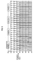
- the honeycomb filters prepared in the above Examples 1 to 3 and Comparative Example were subjected to a rapid cooling test in which the temperatures in the center portion and the outermost peripheral portion were constantly monitored.
- the rapid cooling test was conducted in the following steps: an empty electric furnace is heated to a predetermined set temperature; a sample honeycomb filter is placed in the electric furnace; after closing the cover of the electric furnace, the sample is kept in the electric furnace until the temperature becomes uniform throughout the entire sample; the sample is taken out of the electric furnace to be naturally cooled down on a wire mesh.
- the surface of the sample after being cooled down was observed to examine whether or not any crack has occurred in the coating material coated on the outer surface and in the bonding material.
- the observation results are shown in FIG. 8 .
- “O (circle)” indicates that no crack was observed both in the coating material and bonding material
- X (cross) indicates that the generation of cracks was observed in one of or both of the coating material and the bonding material.
- FIG. 8 shows that the threshold set temperature (safe temperature) at which no crack generation was observed was 500°C or lower in Examples 1 to 3, while the threshold set temperature in the Comparative Example was 450°C or lower. Thus, it is indicated that the generation of cracks is less likely to occur in the honeycomb filters prepared in Examples compared to that in Comparative Example.
- a heat capacity of the segments located in the peripheral portion is higher than that of the segments located in the center portion, a temperature gradient between the peripheral portion and the center portion during the temperature drop after thermal processing process is reduced. Accordingly, thermal stress between the peripheral portion and the center portion during temperature drop becomes smaller, and thereby stress acting on the bonding material disposed between these segments is reduced; thus, it is possible to prevent the generation of cracks in the bonding material. As a result, the production requires less time, allowing efficient honeycomb filter production.
- a heat capacity of the segments in the peripheral portion is higher than that of the segments in the center portion.
- a heat capacity of the segments in the peripheral portion is higher than that of the segments in the center portion.
- a mean bulkhead thickness of the segments located in the peripheral portion is higher than that of the segments located in the peripheral portion
- a heat capacity of the segments in the outer portion is higher than that of the segments in the center portion.
- the fifth aspect of the present invention it is possible not only to conduct efficient exhaust gas purification but also to prevent the generation of cracks in a honeycomb filter during the production.
Landscapes
- Physics & Mathematics (AREA)
- Geometry (AREA)
- Chemical & Material Sciences (AREA)
- Chemical Kinetics & Catalysis (AREA)
- Engineering & Computer Science (AREA)
- Combustion & Propulsion (AREA)
- Mechanical Engineering (AREA)
- General Engineering & Computer Science (AREA)
- Filtering Materials (AREA)
Applications Claiming Priority (1)
| Application Number | Priority Date | Filing Date | Title |
|---|---|---|---|
| PCT/JP2005/019618 WO2007049338A1 (fr) | 2005-10-25 | 2005-10-25 | Filtre en nid d’abeille |
Publications (2)
| Publication Number | Publication Date |
|---|---|
| EP1955751A1 true EP1955751A1 (fr) | 2008-08-13 |
| EP1955751A4 EP1955751A4 (fr) | 2009-12-23 |
Family
ID=37967462
Family Applications (1)
| Application Number | Title | Priority Date | Filing Date |
|---|---|---|---|
| EP05805271A Withdrawn EP1955751A4 (fr) | 2005-10-25 | 2005-10-25 | Filtre en nid d abeille |
Country Status (2)
| Country | Link |
|---|---|
| EP (1) | EP1955751A4 (fr) |
| WO (1) | WO2007049338A1 (fr) |
Families Citing this family (2)
| Publication number | Priority date | Publication date | Assignee | Title |
|---|---|---|---|---|
| DE602007002470D1 (de) * | 2007-02-28 | 2009-10-29 | Ibiden Co Ltd | Wabenstrukturkörper |
| JP5714568B2 (ja) * | 2010-03-31 | 2015-05-07 | 日本碍子株式会社 | ハニカムフィルタ |
Citations (4)
| Publication number | Priority date | Publication date | Assignee | Title |
|---|---|---|---|---|
| EP0867222A2 (fr) * | 1997-03-28 | 1998-09-30 | Ngk Insulators, Ltd. | Structure céramique en nid d'abeilles avec différentes épaisseurs de parois |
| EP1375854A1 (fr) * | 2001-04-03 | 2004-01-02 | Ngk Insulators, Ltd. | Structure en nid d'abeilles et son ensemble |
| EP1440722A1 (fr) * | 2001-10-09 | 2004-07-28 | Ngk Insulators, Ltd. | Filtre en nid d'abeilles |
| EP1484483A1 (fr) * | 2002-02-26 | 2004-12-08 | Ngk Insulators, Ltd. | Filtre a alveoles |
Family Cites Families (5)
| Publication number | Priority date | Publication date | Assignee | Title |
|---|---|---|---|---|
| JP2003010616A (ja) * | 2001-06-29 | 2003-01-14 | Ngk Insulators Ltd | ハニカム構造体 |
| KR100607479B1 (ko) * | 2002-03-01 | 2006-08-02 | 니뽄 가이시 가부시키가이샤 | 배출 가스 정화 시스템, 필터의 압력 손실 산출 방법 및필터의 제조 방법 |
| JP4294964B2 (ja) * | 2002-03-15 | 2009-07-15 | 日本碍子株式会社 | セラミックスハニカム構造体の製造方法 |
| JP2003340224A (ja) * | 2002-05-30 | 2003-12-02 | Ngk Insulators Ltd | ハニカム構造体、及びその製造方法 |
| JP4421858B2 (ja) * | 2003-09-12 | 2010-02-24 | 日本碍子株式会社 | ハニカム構造体及びその製造方法 |
-
2005
- 2005-10-25 EP EP05805271A patent/EP1955751A4/fr not_active Withdrawn
- 2005-10-25 WO PCT/JP2005/019618 patent/WO2007049338A1/fr active Application Filing
Patent Citations (4)
| Publication number | Priority date | Publication date | Assignee | Title |
|---|---|---|---|---|
| EP0867222A2 (fr) * | 1997-03-28 | 1998-09-30 | Ngk Insulators, Ltd. | Structure céramique en nid d'abeilles avec différentes épaisseurs de parois |
| EP1375854A1 (fr) * | 2001-04-03 | 2004-01-02 | Ngk Insulators, Ltd. | Structure en nid d'abeilles et son ensemble |
| EP1440722A1 (fr) * | 2001-10-09 | 2004-07-28 | Ngk Insulators, Ltd. | Filtre en nid d'abeilles |
| EP1484483A1 (fr) * | 2002-02-26 | 2004-12-08 | Ngk Insulators, Ltd. | Filtre a alveoles |
Non-Patent Citations (1)
| Title |
|---|
| See also references of WO2007049338A1 * |
Also Published As
| Publication number | Publication date |
|---|---|
| EP1955751A4 (fr) | 2009-12-23 |
| WO2007049338A1 (fr) | 2007-05-03 |
Similar Documents
| Publication | Publication Date | Title |
|---|---|---|
| JP4408183B2 (ja) | 排ガス浄化用ハニカムフィルター | |
| EP1787969B1 (fr) | Structure en nid d'abeille | |
| KR100855167B1 (ko) | 벌집형 구조체 | |
| JP4870558B2 (ja) | ハニカム構造体及びシール材層 | |
| US7517502B2 (en) | Honeycomb structural body | |
| JP4880581B2 (ja) | セラミックハニカム構造体 | |
| US8283019B2 (en) | Honeycomb structured body | |
| EP2090351B1 (fr) | Corps à structure en nid d'abeilles, appareil de purification de gaz d'échappement et méthode de fabrication de corps à structure en nid d'abeilles | |
| EP1473445A1 (fr) | Structure nid d'abeille | |
| JP4927710B2 (ja) | ハニカム構造体 | |
| US7541006B2 (en) | Honeycomb structured body | |
| WO2003031023A1 (fr) | Filtre en nid d'abeilles | |
| WO2006103786A1 (fr) | Structure en nid d’abeille et materiau d’etancheite | |
| WO2005063653A9 (fr) | Structure en nid d'abeille | |
| WO2007043245A1 (fr) | Unité en nid d’abeilles et structure en nid d’abeilles | |
| KR20080102179A (ko) | 허니콤 세그먼트, 허니콤 구조체 및 그 제조 방법 | |
| JP5103378B2 (ja) | ハニカム構造体 | |
| CN108625932B (zh) | 封孔蜂窝结构体 | |
| US8329111B2 (en) | Honeycomb filter and method for manufacturing the same | |
| CN111749756B (zh) | 颗粒过滤器及装罐结构体 | |
| JP2009255037A (ja) | ハニカム構造体 | |
| EP2105181B1 (fr) | Corps structuré en nid d'abeille | |
| US20090010817A1 (en) | Honeycomb filter | |
| EP2221099B1 (fr) | Structure en nid d'abeille | |
| EP1955751A1 (fr) | Filtre en nid d abeille |
Legal Events
| Date | Code | Title | Description |
|---|---|---|---|
| PUAI | Public reference made under article 153(3) epc to a published international application that has entered the european phase |
Free format text: ORIGINAL CODE: 0009012 |
|
| 17P | Request for examination filed |
Effective date: 20080513 |
|
| AK | Designated contracting states |
Kind code of ref document: A1 Designated state(s): DE FR PL |
|
| RBV | Designated contracting states (corrected) |
Designated state(s): DE FR PL |
|
| A4 | Supplementary search report drawn up and despatched |
Effective date: 20091119 |
|
| RIC1 | Information provided on ipc code assigned before grant |
Ipc: F01N 3/022 20060101ALI20091113BHEP Ipc: B01D 46/24 20060101ALI20091113BHEP Ipc: B01D 39/20 20060101AFI20070627BHEP |
|
| 17Q | First examination report despatched |
Effective date: 20100323 |
|
| STAA | Information on the status of an ep patent application or granted ep patent |
Free format text: STATUS: THE APPLICATION IS DEEMED TO BE WITHDRAWN |
|
| 18D | Application deemed to be withdrawn |
Effective date: 20100803 |