EP1955107B1 - Collecteurs de lumière pour systèmes de projection - Google Patents
Collecteurs de lumière pour systèmes de projection Download PDFInfo
- Publication number
- EP1955107B1 EP1955107B1 EP07840434A EP07840434A EP1955107B1 EP 1955107 B1 EP1955107 B1 EP 1955107B1 EP 07840434 A EP07840434 A EP 07840434A EP 07840434 A EP07840434 A EP 07840434A EP 1955107 B1 EP1955107 B1 EP 1955107B1
- Authority
- EP
- European Patent Office
- Prior art keywords
- light
- output
- lightpipe
- operable
- light source
- Prior art date
- Legal status (The legal status is an assumption and is not a legal conclusion. Google has not performed a legal analysis and makes no representation as to the accuracy of the status listed.)
- Not-in-force
Links
Images


Classifications
-
- G—PHYSICS
- G02—OPTICS
- G02B—OPTICAL ELEMENTS, SYSTEMS OR APPARATUS
- G02B6/00—Light guides; Structural details of arrangements comprising light guides and other optical elements, e.g. couplings
- G02B6/0001—Light guides; Structural details of arrangements comprising light guides and other optical elements, e.g. couplings specially adapted for lighting devices or systems
- G02B6/0096—Light guides; Structural details of arrangements comprising light guides and other optical elements, e.g. couplings specially adapted for lighting devices or systems the lights guides being of the hollow type
-
- G—PHYSICS
- G02—OPTICS
- G02B—OPTICAL ELEMENTS, SYSTEMS OR APPARATUS
- G02B27/00—Optical systems or apparatus not provided for by any of the groups G02B1/00 - G02B26/00, G02B30/00
- G02B27/09—Beam shaping, e.g. changing the cross-sectional area, not otherwise provided for
- G02B27/0938—Using specific optical elements
- G02B27/0994—Fibers, light pipes
-
- G—PHYSICS
- G02—OPTICS
- G02B—OPTICAL ELEMENTS, SYSTEMS OR APPARATUS
- G02B27/00—Optical systems or apparatus not provided for by any of the groups G02B1/00 - G02B26/00, G02B30/00
- G02B27/28—Optical systems or apparatus not provided for by any of the groups G02B1/00 - G02B26/00, G02B30/00 for polarising
- G02B27/283—Optical systems or apparatus not provided for by any of the groups G02B1/00 - G02B26/00, G02B30/00 for polarising used for beam splitting or combining
-
- G—PHYSICS
- G03—PHOTOGRAPHY; CINEMATOGRAPHY; ANALOGOUS TECHNIQUES USING WAVES OTHER THAN OPTICAL WAVES; ELECTROGRAPHY; HOLOGRAPHY
- G03B—APPARATUS OR ARRANGEMENTS FOR TAKING PHOTOGRAPHS OR FOR PROJECTING OR VIEWING THEM; APPARATUS OR ARRANGEMENTS EMPLOYING ANALOGOUS TECHNIQUES USING WAVES OTHER THAN OPTICAL WAVES; ACCESSORIES THEREFOR
- G03B21/00—Projectors or projection-type viewers; Accessories therefor
- G03B21/14—Details
- G03B21/20—Lamp housings
- G03B21/2006—Lamp housings characterised by the light source
- G03B21/2013—Plural light sources
-
- G—PHYSICS
- G03—PHOTOGRAPHY; CINEMATOGRAPHY; ANALOGOUS TECHNIQUES USING WAVES OTHER THAN OPTICAL WAVES; ELECTROGRAPHY; HOLOGRAPHY
- G03B—APPARATUS OR ARRANGEMENTS FOR TAKING PHOTOGRAPHS OR FOR PROJECTING OR VIEWING THEM; APPARATUS OR ARRANGEMENTS EMPLOYING ANALOGOUS TECHNIQUES USING WAVES OTHER THAN OPTICAL WAVES; ACCESSORIES THEREFOR
- G03B21/00—Projectors or projection-type viewers; Accessories therefor
- G03B21/14—Details
- G03B21/20—Lamp housings
- G03B21/208—Homogenising, shaping of the illumination light
-
- H—ELECTRICITY
- H04—ELECTRIC COMMUNICATION TECHNIQUE
- H04N—PICTORIAL COMMUNICATION, e.g. TELEVISION
- H04N9/00—Details of colour television systems
- H04N9/12—Picture reproducers
- H04N9/31—Projection devices for colour picture display, e.g. using electronic spatial light modulators [ESLM]
- H04N9/3141—Constructional details thereof
- H04N9/315—Modulator illumination systems
- H04N9/3152—Modulator illumination systems for shaping the light beam
-
- H—ELECTRICITY
- H04—ELECTRIC COMMUNICATION TECHNIQUE
- H04N—PICTORIAL COMMUNICATION, e.g. TELEVISION
- H04N9/00—Details of colour television systems
- H04N9/12—Picture reproducers
- H04N9/31—Projection devices for colour picture display, e.g. using electronic spatial light modulators [ESLM]
- H04N9/3141—Constructional details thereof
- H04N9/315—Modulator illumination systems
- H04N9/3158—Modulator illumination systems for controlling the spectrum
-
- H—ELECTRICITY
- H04—ELECTRIC COMMUNICATION TECHNIQUE
- H04N—PICTORIAL COMMUNICATION, e.g. TELEVISION
- H04N9/00—Details of colour television systems
- H04N9/12—Picture reproducers
- H04N9/31—Projection devices for colour picture display, e.g. using electronic spatial light modulators [ESLM]
- H04N9/3141—Constructional details thereof
- H04N9/315—Modulator illumination systems
- H04N9/3167—Modulator illumination systems for polarizing the light beam
Definitions
- This disclosure generally relates to a light collection system, and more specifically relates to a non-imaging collector for a projection system.
- Étendue is a property of an optical system. It is given by the cross-sectional area of a cone of light (in the plane perpendicular to the propagation direction), times the solid angle subtended by the light. Other names for this property are acceptance, throughput, light-grasp, collecting power, and the AS2 product. Étendue is important because it never increases in any optical system. A perfect optical system produces an image with the same étendue as the source.
- étendue is in determining optical system throughput. Any given source emits light into an optical system with efficiency dependent on the system étendue. Most surface emitting light sources (e.g ., light emitting diodes) do not match the étendue required of projection panels. The die are either too small, requiring the addition of die, or too large, requiring some sort of aperture to reduce the LED étendue to match the panel étendue.
- US 2006/007538 discloses an optical system in which light fro sources 210 and 220 is directed towards a polarizing beam splitter to be combined and then directed towards a lens.
- US 2006/002109 describes a projection apparatus having a white light source in combination with a color selecting filter wheel for selecting a color. It also includes LED emitters and means for combining the light.
- WO2005/099277 discloses an arrangement where light from different light sources is combined at a polarizing beam splitter.
- the light collectors gather light from surface emitting sources (e.g., LEDs) of differing color using input lightpipes.
- a light collection system splits the light into orthogonal linear polarization states and efficiently propagates the light by use of a polarizing beamsplitter (PBS) and a reflecting element.
- PBS polarizing beamsplitter
- the light collection system may be integrated into a single, monolithic glass, plastic or combination glass/plastic assembly.
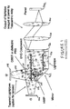
- Figure 1 is a schematic diagram of a first embodiment of a light collection system in accordance with the present disclosure
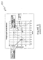
- Figure 2 is a graph illustrating angular intensity distribution in the far field for exemplary red, green, and blue Light Emitting Diode (LED) devices in accordance with the present disclosure
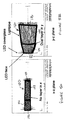
- Figure 3A is a schematic diagram illustrating the relationship of luminous output to the aperture die area of an LED in accordance with the present disclosure
- Figure 3B is a schematic diagram illustrating the relationship of luminous output to the aperture angular output of an LED in accordance with the present disclosure
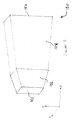
- Figure 4 is a schematic diagram showing a three-dimensional view of an exemplary tapered lightpipe in accordance with the present disclosure
- Figure 5A is a schematic diagram showing a top view of the exemplary tapered lightpipe of Figure 4 ;
- Figure 5B is a schematic diagram showing a side view of the exemplary tapered lightpipe of Figure 4 ;
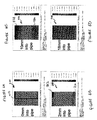
- Figure 6A is a graph illustrating cross-sectional illuminance through the output lightpipe of Figure 1 at a position of 0mm along the optical axis, in accordance with the present disclosure
- Figure 6B is a graph illustrating cross-sectional illuminance through the output lightpipe of Figure 1 at a position of 0mm along the optical axis, in accordance with the present disclosure
- Figure 6C is a graph illustrating cross-sectional illuminance through the output lightpipe of Figure 1 at a position of 0mm along the optical axis, in accordance with the present disclosure
- Figure 6D is a graph illustrating cross-sectional illuminance through the output lightpipe of Figure 1 at a position of 0mm along the optical axis, in accordance with the present disclosure
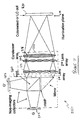
- Figure 7 is a schematic diagram illustrating a second light collection system, including lens arrays and condenser homogenizing optics;
- Figure 8 is a schematic diagram illustrating a third light collection system, including lens arrays and condenser homogenizing optics with a first lens array attached to a prism assembly;
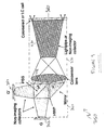
- Figure 9 is a schematic diagram illustrating a fourth light collection system, including a condenser lens and a non-imaging collector as the homogenizing optic;
- Figure 10 is a schematic diagram illustrating a fifth light collection system, including a condenser lens and field lens as the homogenizing optic;
- Figure 11 is a schematic diagram illustrating a sixth light collection system, which provides light recycling
- Figure 12 is a schematic diagram illustrating a seventh light collection system, which provides light recycling with a homogenizing optic at the output;
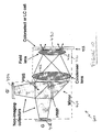
- Figure 13 is a schematic diagram illustrating an eighth light collection system, with a dual PBS structure.
- Figure 14 is a schematic diagram illustrating a ninth light collection system.
- the light source combining devices for use in projection applications.
- the light source combining devices may provide a linearly polarized, spatially uniform output with well defined output area and distribution angles to an LCOS, DLP or LCD modulating panel.
- the illuminator provides higher luminous output into a given étendue.
- FIG. 1 is a schematic diagram of a first embodiment of a light collection system 100 constituting an embodiment of the invention.
- Light collection system 100 includes tapered lightpipes 102, 106, a polarization beam splitter (PBS) 110, a polarization rotation element 120, a reflecting element 122, an output lightpipe 124, and a G'/G ColorSelect ® filter 126, arranged as shown.
- PBS polarization beam splitter
- the first tapered lightpipe 102 is optically coupled to a first input port 112 of the PBS 110, which may be a PBS having a multilayer birefringent structure (e.g. a VikuitiTM PBS, as provided by 3M, Corp.), a dielectric PBS, or the like.
- a second tapered lightpipe 106 is optically coupled to a second input port 114 of the PBS 110.
- First light source G 104 and second light source G' 108 may be provided by surface emitting color sources such as light emitting diodes (LEDs). Light sources 104, 108 are optically coupled to input ports of respective tapered lightpipes 102, 106.
- a polarization rotation element 120 may be provided by a halfwave plate (HWP), located at a first output port 116 of the PBS 110.
- Polarization rotation element 120 serves to transform the state of polarization from p-polarized light to s-polarized light, and vice versa.
- polarization rotation element 120 may be provided by a film.
- a reflecting element 122 may be optically coupled to the polarization rotation element 120, and an output lightpipe 124 may be optically coupled to the second output port 118 of the PBS 110 and the reflecting element 122 to collect light therefrom.
- the polarization rotation element 120 is located between the output port 116 and reflecting element 122, in other embodiments it could instead be located between the reflecting element 122 and the output lightpipe 124.
- the G'/G ColorSelect filter 126 is located in the lightpath of exiting light from output lightpipe 124.
- G'/G ColorSelect ® filter 126 is used as an exemplary filter for colors G and G', as output by light sources 104 and 108 respectively.
- ColorSelect filters are manufactured by ColorLink, Inc., located in Boulder, Colorado, and utilize retarder stacks to rotate the state of polarization of an additive color band (e.g., color G) by 90°, while the complementary color band (e.g., color G') retains the input state of polarization.
- Examples of G'/G configurations include but are not limited to Green/Magenta, Red/Cyan, and Blue/Yellow.
- a linear cleanup polarizer (not shown) may also be located in the light path following the G'/G ColorSelect ® filter 126 to provide more uniform polarized output light.
- Lenses 128 and 130 may be configured as a telecentric relay system to direct output light to an LCOS, DLP, or LCD modulating panel 132. It should be appreciated that other embodiments, some of which are provided herein, may provide alternative imaging or relay optical networks to direct light toward panel 132.
- light from distinctly different surface emitting color sources 104 and 108 (labeled G and G' in this case; note their spectral regions may overlap in some embodiments) is collected and transmitted toward the first and second input ports (112 and 114) of the PBS 110.
- s-polarized light from each source 104 and 108 is reflected by the PBS 110, while p-polarized light is transmitted.
- the G' p-polarized light 138 and G s-polarized light 140 propagates toward the polarization rotation element 120 at the first output port 116, where they are both rotated 90 degrees to s-polarized and p-polarized light respectively.
- Reflecting element 122 then reflects the light from the polarization rotation element 120 toward lightpipe 124.
- G p-polarized light 134 and G' s-polarized light 136 propagates toward the second output port 118.
- all G light enters the output lightpipe with p-polarization and all G' light enters with s-polarized light.
- the output lightpipe may homogenize the spatial distribution of both G and G' light independently (with some loss in polarization purity), and effectively eliminates the edge effect that may be caused by a HWP 120.
- the G and G' light then passes through a G'/G ColorSelect filter 126, which rotates the G' light 90 degrees and does not rotate the G light.
- the output is a uniform mixture of p-polarized G and G' light that can be imaged with relay optics to a panel.
- a linear polarizer (not shown) may be placed after the ColorSelect filter for polarization cleanup. Outputting light with one common polarization may be particularly useful for applications that utilize liquid crystal panels to modulate light, but may be less desirable for projection applications utilizing micromirrors to modulate light ( i.e., DLP techniques).
- Figure 2 provides a graph 150 illustrating angular intensity distribution in the far field for exemplary high-power red, green, and blue LED devices (in this case, from Luminus Devices). From the graph 150, it may be observed that the intensity of each of the red, green, and blue devices is not uniform with angle. Furthermore, the red device (as shown by line 152) has a nearly Lambertian normalized intensity profile, while the blue and green devices (shown by line 154) have a more peaked normalized intensity profile.
- FIGS. 3A and 3B illustrate two techniques for reducing étendue at LEDs 160 and 170 respectively.
- the first technique involves varying the aperture 164 at the die 162. Since the die 162 can be thought of as a surface with an infinite number of point emitters, a reduction in die area produces a proportional reduction in luminous output.
- the second technique for reducing étendue as illustrated by LED 170 in FIGURE 3B , involves varying collected angular output.
- the second technique may result in a lower loss in luminous output for 'peaked' green and blue die.
- FIG 4 is a schematic diagram showing a three-dimensional view of an exemplary tapered lightpipe 180.
- the tapered lightpipe 180 provides an angle-to-angle transformer intended to reduce the collected angular distribution from an LED source with non-uniform angular output, while maintaining a high transfer efficiency.
- tapered lightpipe 180 has a light source input end 182 and a light source output end 184.
- the lightpipe 180 has a dual taper in the y-z plane, such that the first and second tapered stages 186 and 188 decrease in cross-sectional area along an axis normal to the cross-sectional plane (z axis), with the first tapered stage 186 decreasing in cross-sectional area per unit length at a greater rate than the second tapered stage 188 decreases.
- lightpipe 180 transforms LED output angles up to 53 degrees to output angles of 23 degrees or less.
- the lightpipe is not tapered (although it could be in other embodiments), and LED output angle of 23 degrees or less are output into a cone of 23 degrees or less. These angles were selected such that substantially all of the die face could emit light into the collection system, and the output of the lightpipe 180 would match the étendue of a selected panel.
- the tapered light pipe 180 collects 1.5 to 1.75 times more light into the desired étendue than if an étendue-reducing aperture were placed at the die face.
- the angle-to-angle transformer can also be implemented with a tapered lightpipe/tunnel and CPC for higher efficiency. A lens at the output of the angle-to-angle transformer may further increase efficiency.
- Figure 5A is a schematic diagram showing a top view of the exemplary tapered lightpipe 180 of Figure 4 . From this view, it can be seen that the exemplary tapered lightpipe 180 is not tapered in the x-z plane. Although an exemplary tapered lightpipe is herein disclosed that is tapered in one dimension and not another, in other embodiments, the lightpipe may be tapered in other combinations of dimensions. For example, there may be a taper in the x-z plane.
- Figure 5B is a schematic diagram showing a side view of the exemplary lightpipe 180 of Figure 4 .
- Figures 6A-6D depict cross-sectional illuminance plots 200, 210, 220, 230 through the output lightpipe 124 (of Figure 1 ) as a function of position along the optical axis.
- the light in the lightpipe 124 has been properly scaled for losses that are expected to be incurred during passage through the PBS and reflecting element (right angle prism structure).
- Figure 6A illustrates that at a 0mm position along the optical axis (i.e., at the input of the output lightpipe124), a shaded area 202 is evident where the half-wave plate is located between the PBS and reflecting element.
- Figures 6B and 6C show that further into the output lightpipe, for instance at 2mm and 10mm from the input face in the direction of the optic axis, the HWP shading is reduced, but light pooling is apparent along two edges ( e.g. , shown by shaded areas 212, 214 in Figure 6B , and shaded areas 222, 224 in Figure 6C).
- Figure 6D shows that at approximately 18mm from the input of the output lightpipe, the light is homogenized sufficiently for use in projection applications.
- the output lightpipe may alternatively be implemented as a dual tapered lightpipe or tapered lightpipe with a compound parabolic concentrator (CPC) for the purpose of implementing lower f-number relay optics.
- CPC compound parabolic concentrator
- a lens at the output of the angle-to-angle transformer may further increase efficiency.
- Figure 7 illustrates a second light collection system 250, including light collection module 260 and homogenizing optical module 270.
- Light collection module 260 receives light from first and second light sources 252, 254, and may have similar structure, and may operate in much the same way as elements 102-122 of Figure 1 .
- Homogenizing optical module 270 generally provides homogenizing optics, and includes first lens array 272 and second lens array 274 (each with two or more lenslets) and a condenser lens 276. The images of each lenslet in the first lens array 272 may be imaged by the second lens array 274 and condenser 276 at the illumination plane 278. The overlapping images provide substantially uniform light at the illumination plane 278.
- a ColorSelect filter 280 may be placed in the lens train to rotate all of the light to one common polarization.
- the ColorSelect filter 280 can be substituted for an LC cell (a switchable half-wave rotator) to provide output light with a common polarization.
- LC cell a switchable half-wave rotator
- FIG 8 illustrates a third light collection system 300, including light collection module 310 and homogenizing optical module 320.
- homogenizing optical module 320 provides a first lens array 322 attached to the face of the prism assembly 312 and also attached to output port of PBS 314 with low index adhesive to optimize total internal reflection (TIR) of light.
- First lens array 322, in conjunction with second lens array 324 and condenser lens 326 directs light toward illumination plane 328.
- a ColorSelect element 330 may be placed in the lens train to rotate all of the light to one common polarization.
- this embodiment may provide the advantage of higher polarization purity at the output compared to the lightpipe homogenizing optic 124 shown in Figure 1 .
- the ColorSelect filter 330 can be substituted for an LC cell (a switchable half-wave rotator) to provide output light with a common polarization. Such an arrangment is described in Figure 14 , however, the switching technique described for that embodiment may be used with this architecture also.
- Figure 9 illustrates a fourth light collection system 350 (and being one which constitutes an embodiment of the present invention), including light collection module 360 and homogenizing optical module 370.
- the structure and function of light collection module 360 is similar to that shown by the first embodiment described with reference to Figure 1 .
- the homogenizing optical module 370 includes a condenser lens 372 and lightpipe 374 (or similar non-imaging collector such as a light tunnel, solid Compound Parabolic Concentrator (CPC), hollow CPC, solid angle-angle transformer, or hollow angle-angle transformer) acting as the homogenizing optic.
- CPC Solid Compound Parabolic Concentrator
- light collection module 360 receives light from first and second light sources 352, 354, and directs light toward PBS output port 362 and prism output port 364, in a similar manner to the embodiment described in Figure 1 .
- the condenser lens 372 directs light from the output of the light collection module 360 to the input of the non-imaging collector 370, where the light is homogenized.
- the angular distribution of the illumination may be tailored to match a desired relay lens numerical aperture by tapering or shaping the non-imaging collector 374.
- the condenser lens 372 is shown with an air gap between the lens and prism assembly.
- the condenser lens 372 may alternatively be optically coupled to the prism assembly with low index adhesive.
- the ColorSelect filter 380 can be substituted for an LC cell (a switchable half-wave rotator) to provide output light with a common polarization.
- LC cell a switchable half-wave rotator
- Figure 10 illustrates a fifth light collection system 400 configured to receive light from first and second light sources 402, 404, including light collection module 410 and homogenizing optical module 420.
- the structure and function of light collection module 410 is similar to that shown by the first embodiment described with reference to Figure 1 .
- Homogenizing optical module 420 includes a condenser lens 422 and field lens 424.
- the field lens 422 functions to create a telecentric source at the illumination plane 428.
- system 400 may utilize several lenses for the condenser lens 422 and field lens 424, respectively.
- light collection system 400 may provide a potentially higher polarization purity than a lightpipe or light tunnel-based system.
- the condenser lens 422 may be optically coupled light collection module 410 with low index adhesive.
- the ColorSelect filter 430 can be substituted for an LC cell (a switchable half-wave rotator) to provide output light with a common polarization.
- LC cell a switchable half-wave rotator
- Figure 11 illustrates a sixth light collection system 450, providing an alternative architecture.
- Light collection system 450 includes first and second light collectors 456, 458 operable to receive light from first and second light sources 452, 454.
- Light collection system 450 further includes first and second quarter wave plates (QWP) 460, 462 located between first and second light collectors 456, 458 and first and second input ports 464, 466 of PBS 470.
- QWP quarter wave plates
- a flat mirror 472 is located at port 474 of PBS 470.
- a ColorSelect element may be located in the output light path transmitted via output port 476 to provide output light with one common polarization.
- the ColorSelect filter 480 can be substituted for an LC cell (a switchable half-wave rotator) to provide output light with a common polarization.
- LC cell a switchable half-wave rotator
- randomly-polarized light (G) emitted by first light source 452 is transmitted to the QWP 460 and PBS 470 via the first light collector 456.
- G randomly-polarized light
- s-polarized light is reflected toward the PBS output port 476, while p-polarized light is transmitted toward the mirror 472.
- the p-polarized light reflects from the mirror 472, passes through the PBS surface 465, and passes through QWP 460, which transforms the light to a circularly-polarized state.
- the circular-polarized light reflects again at the surface 453 of the LED 452 (surface reflectivity ⁇ 25%), changes handedness, and passes again through the QWP 460.
- this light After passing through the QWP 460, this light is now s-polarized, and reflects from the PBS surface 465 toward the PBS output port 476. Illumination from the second light source 452 (G' LED) follows a similar path/recycling, except the s-polarized light is recycled while the p-polarized light is directly transmitted.
- the first and second light collectors 456, 458 and PBS 470 can be sized to capture the full panel étendue (compared to half the panel étendue in the previous architectures of Figs 1 , 7-10 ). Additionally, the output of the PBS 470 may be directly imaged to the modulating panel since there are no seams in the output face. Finally, polarization purity at the output face 476 of the PBS 470 should be very good.
- Figure 12 illustrates a seventh light collection system 500 constituting an embodiment of the present invention.
- This system 500 has a similar architecture to that shown in Figure 11 , except a lightpipe 502 (or other non-imaging collector such as a light tunnel, solid or hollow CPC, or lens array and condenser) has been added at the output for homogenizing the illumination.
- the lightpipe 502, or equivalent may be attached with low index adhesive.
- Figure 13 illustrates an eighth light collection system 550 and being an arrangement that constitutes an embodiment of the present invention.
- This exemplary architecture uses first and second polarizing beamsplitters in orthogonal orientations, where a first PBS 552 reflects s-polarized light and a second PBS 554 reflects p-polarized light.
- Dual Brightness Enhancement Film (DBEF, from 3M Corp.) is capable of this type of operation.
- randomly polarized light from first light source (G' LED) 556 transmits to the first PBS layer 560, where the s-polarized light 561 is reflected to the output 562 and the p-polarized light 563 is transmitted.
- the p-polarized light 563 then reflects at the second PBS layer 566, and is converted to circularly-polarized light after passing through the QWP 568.
- the circularly-polarized light changes handedness at the mirror 570, and is converted to s-polarized light after passing through the QWP 568 again.
- the s-polarized light then transmits through the PBS to the output 562.
- a lightpipe 572 (or other homogenizing optical structure) is included at the output 562 to provide uniform illumination.
- the lightpipe 572 may also be attached with low index adhesive. Randomly polarized light from second light source (G LED) 558 is processed in much the same way as that from the first light source, except p-polarized light is reflected at the second PBS layer 566 to the output 562 and the s-polarized light is transmitted.
- a ColorSelect element may be located in the output light path to provide output light with one common polarization.
- the ColorSelect filter 574 can be substituted for an LC cell (a switchable half-wave rotator) to provide output light with a common polarization.
- LC cell a switchable half-wave rotator
- the instantaneous light flux output by a light emitting diode is nearly linearly dependent on the instantaneous current input to the device.
- LED's can be driven with continuous wave (CW) currents, or can be pulsed with higher peak currents when the current is modulated over short periods of time (fractions of a second).
- LED manufacturers provide maximum pulsed and CW current limits for their products which produce device lifetimes (usually 20,000-100,000 hours) that are similar for either drive method.
- the average light flux produced by an LED that is pulsed at the manufacturer's limit pulse current over a long period of time is not greater than the average light flux produced by an LED driven with the manufacturer's limit CW current. For a single LED, this implies the brightest light output will generally be seen with a CW driven LED.
- Figure 14 illustrates a variation of a non-imaging light collection system (compared to the various embodiments of Figures 1-13 ) that approximately doubles the brightness of the same system when compared to a single color LED input.
- the structure of light collection system 600 is similar to the light collection system 100 of Figure 1 , with a few modifications. For instance, in this arrangement, first and second light sources (LEDs) 602, 604 are of the same color (or similar color), and the ColorSelect filter shown in Figure 1 is replaced with a switchable half-wave rotator (e.g. , a liquid crystal cell) and analyzer 606.
- a switchable half-wave rotator e.g. , a liquid crystal cell
- Figures 1-13 show, among other things, that the use of two substantially distinct colors (or spectral distributions) at the inputs of the light collectors and a ColorSelect device at the output, produce a brighter light source. If the LEDs are replaced with LEDs of the same color (or similar color) 602, 604, and the ColorSelect filter is replaced with a switchable half-wave rotator (e.g ., a liquid crystal cell) and analyzer 606, light from either light source 602, 604 can be selected at the output based on the driven phase of the half wave rotator 606.
- a switchable half-wave rotator e.g ., a liquid crystal cell
- the average light flux out of the illuminator can be approximately twice the CW output of a single LED source.
- the same system can be applied to sources that are spectrally separated by an amount less than the sum of half the bandwidths of each source. For example, a bluish green LED might be combined with a yellowish green LED to produce a bright green source in a 2D display. The same illuminator could then be combined with a higher frame rate display for displaying two images in spectral-division 3D applications.
- the light collection systems described herein may be implemented as a monolithic glass, plastic, or combination glass/plastic assembly.
- Total internal reflection (TIR) is required at several faces of the PBS and right angle prism to maintain 6tendue and efficiency as light travels through the structure.
- dielectric layers on the glass surfaces may allow lower index glass or plastic to be used with glue to maintain the TIR.
- the monolithic assembly provides advantages in robustness, alignment, and potentially cost if components can be molded from plastic.
- the tapered lightpipes of Figure 1 may be utilized to interface LED sources with the color combining and polarization splitting architectures described in U.S. Pub. App. No. 2006/0007538 A1, by M. G. Robinson , entitled “Illumination Systems,” filed July 6, 2005.
- the output lightpipes may be used to direct light from the output ports of the PBSs/mirrors shown in 2006/0007538 in accordance with the teachings of this disclosure, in order to homogenize output light.
- the teachings of this disclosure and 2006/0007538 may be combined to provide various light collection systems for projection systems.
- the term "projection system” refers to a display that projects an image onto a screen, including rear-projection systems and front-projection systems.
- optically coupled refers to the coupling of optical components to provide a light path and light transmission from one component to another.
- Optical components may be integrated with other optical components into a single, monolithic glass, plastic or combination glass/plastic assembly, yet functionally those optical components may still be “optically coupled.”
- Optical coupling may include direct or indirect contact between components, and may or may not include the use of index-matching material, including but not limited to index matching adhesive to couple components together.
- components may be optically coupled when they are touching, when they are integrated as a single assembly, when there is a translucent object between components, and/or when there is a gap between them, provided that a light path is provided between one component and another.
Landscapes
- Physics & Mathematics (AREA)
- General Physics & Mathematics (AREA)
- Engineering & Computer Science (AREA)
- Multimedia (AREA)
- Signal Processing (AREA)
- Optics & Photonics (AREA)
- Projection Apparatus (AREA)
- Non-Portable Lighting Devices Or Systems Thereof (AREA)
- Led Device Packages (AREA)
- Optical Elements Other Than Lenses (AREA)
- Cathode-Ray Tubes And Fluorescent Screens For Display (AREA)
- Devices For Indicating Variable Information By Combining Individual Elements (AREA)
Claims (12)
- Appareil pour un système de projection, se composant de :une première source lumineuse (104) et un premier phototube (102) capable de recevoir de la lumière par la première source lumineuse (104) ;une seconde source lumineuse (108) et un second phototube (106) capable de recevoir de la lumière par la seconde source lumineuse (108) ;un séparateur de polarisation (110) possédant un premier (112) et un second (114) ports d'entrée et un premier (116) et un second (118) ports de sortie, le premier et le second phototubes (102, 104) étant respectivement optiquement couplés au premier et second ports d'entrée ;un élément faisant tourner le plan de polarisation (120) optiquement couplé au premier port de sortie, etun élément réfléchissant (122) optiquement couplé à l'élément de rotation de la polarisation. L'élément réfléchissant (dioptre) étant capable de diriger la lumière depuis l'élément de rotation de la polarisation, caractérisé en ce qu'il comprend un troisième phototube (124) ayant une première extrémité optiquement couplée au second port de sortie (118) et l'élément réfléchissant, le phototube étant capable de transmettre la lumière à une seconde extrémité, un filtre de bloc de lames retard sélecteur de longueur d'onde étant capable de polariser un spectre de couleur supplémentaire le long d'un premier axe, et son spectre de couleur complémentaire le long d'un second axe, et dans lequel la première source lumineuse (104) est capable de sortir un spectre de couleur supplémentaire ; et la seconde source de lumière (108) est capable de sortir un spectre de couleur particulièrement complémentaire au premier spectre de couleur supplémentaire.
- Un appareil selon la revendication 1, dans lequel la première et seconde sources lumineuses sont composées de diodes électroluminescentes.
- Appareil selon la revendication 1, dans lequel les premier et second phototubes (102 et 106) sont coniques.
- Appareil selon la revendication 3 dans laquelle la section en coupe des phototubes coniques est plus petite du côté de la source.
- Appareil selon la revendication 1, dans lequel au moins un des premier et second phototubes (102, 106) se compose d'une première section conique et d'une deuxième section conique.
- Appareil selon la revendication 5, dans lequel la section transversale des première et seconde sections coniques décroit selon un axe normal par rapport au plan de section transversal, dans lequel la première section conique décroit transversalement par unité de longueur à un taux supérieur à celui de la première section conique.
- Appareil selon n'importe laquelle des revendications précédentes, dans lequel l'élément de rotation de la polarisation (120) est capable de faire passer un état de polarisation ordinaire à un état de polarisation orthogonal.
- Appareil selon n'importe laquelle des revendications précédentes, dans lequel l'élément de rotation de la polarisation (120) est une lame demi-onde.
- Appareil selon n'importe laquelle des revendications précédentes, dans lequel l'élément réfléchissant (122) fait partie d'un prisme et d'un miroir.
- Appareil selon n'importe laquelle des revendications précédentes, se composant d'autre part d'un relais optique télécentrique (128, 130) et d'un volet de modulation (132), le relais télécentrique capable de diriger la lumière vers le volet de modulation.
- Appareil selon n'importe laquelle des revendications précédentes, dans lequel l'élément réfléchissant est configuré pour diriger la lumière en un faisceau particulièrement parallèle à la lumière arrivant du second port de sortie.
- Appareil selon n'importe laquelle des revendications précédentes, dans lequel l'état de polarisation de la lumière sortant du troisième phototube et arrivant de la première source lumineuse est particulièrement orthogonal par rapport à la lumière sortant du troisième phototube et provenant de la seconde source lumineuse.
Applications Claiming Priority (4)
| Application Number | Priority Date | Filing Date | Title |
|---|---|---|---|
| US80770406P | 2006-07-18 | 2006-07-18 | |
| US82949506P | 2006-10-13 | 2006-10-13 | |
| US86241406P | 2006-10-20 | 2006-10-20 | |
| PCT/US2007/073809 WO2008011480A2 (fr) | 2006-07-18 | 2007-07-18 | Collecteurs de lumière pour systèmes de projection |
Publications (3)
| Publication Number | Publication Date |
|---|---|
| EP1955107A2 EP1955107A2 (fr) | 2008-08-13 |
| EP1955107A4 EP1955107A4 (fr) | 2011-01-26 |
| EP1955107B1 true EP1955107B1 (fr) | 2012-02-22 |
Family
ID=38957596
Family Applications (1)
| Application Number | Title | Priority Date | Filing Date |
|---|---|---|---|
| EP07840434A Not-in-force EP1955107B1 (fr) | 2006-07-18 | 2007-07-18 | Collecteurs de lumière pour systèmes de projection |
Country Status (5)
| Country | Link |
|---|---|
| US (3) | US7542206B2 (fr) |
| EP (1) | EP1955107B1 (fr) |
| JP (1) | JP5378211B2 (fr) |
| AT (1) | ATE546751T1 (fr) |
| WO (1) | WO2008011480A2 (fr) |
Families Citing this family (62)
| Publication number | Priority date | Publication date | Assignee | Title |
|---|---|---|---|---|
| US7692861B2 (en) * | 2004-07-06 | 2010-04-06 | Real D | Illumination systems |
| JP2007322584A (ja) * | 2006-05-31 | 2007-12-13 | Sanyo Electric Co Ltd | 照明装置及びそれを用いた投写型映像表示装置 |
| ATE546751T1 (de) * | 2006-07-18 | 2012-03-15 | Reald Inc | Lichtkollektoren für projektionssysteme |
| US20080231953A1 (en) * | 2007-03-22 | 2008-09-25 | Young Garrett J | System and Method for LED Polarization Recycling |
| US7821713B2 (en) * | 2007-05-18 | 2010-10-26 | 3M Innovative Properties Company | Color light combining system for optical projector |
| EP2235582A1 (fr) * | 2007-12-28 | 2010-10-06 | 3M Innovative Properties Company | Combineur de lumière |
| EP2238498A1 (fr) * | 2007-12-28 | 2010-10-13 | 3M Innovative Properties Company | Coupleur de lumière |
| US20090190101A1 (en) * | 2008-01-28 | 2009-07-30 | International Business Machines Corporation | Double-Reverse Total-Internal-Reflection-Prism Optical Engine |
| TWI372304B (en) * | 2008-02-12 | 2012-09-11 | Young Optics Inc | Polarization conversion system and illumination module |
| EP2286296A4 (fr) * | 2008-05-15 | 2011-09-07 | 3M Innovative Properties Co | Élément optique et combineur de couleurs |
| CN102089701B (zh) * | 2008-05-15 | 2012-12-26 | 3M创新有限公司 | 光学元件和合色器 |
| EP2288847B1 (fr) * | 2008-06-10 | 2018-11-14 | Philips Lighting Holding B.V. | Dispositif d émission de lumière et procédé associé |
| US20090316114A1 (en) * | 2008-06-18 | 2009-12-24 | Dolby Laboratories Licensing Corporation | Method and apparatus for light recapture and sequential channel illumination |
| US8760507B2 (en) * | 2008-08-05 | 2014-06-24 | Inspectron, Inc. | Light pipe for imaging head of video inspection device |
| USD603445S1 (en) | 2009-03-13 | 2009-11-03 | X6D Limited | 3D glasses |
| USRE45394E1 (en) | 2008-10-20 | 2015-03-03 | X6D Limited | 3D glasses |
| USD624952S1 (en) | 2008-10-20 | 2010-10-05 | X6D Ltd. | 3D glasses |
| USD666663S1 (en) | 2008-10-20 | 2012-09-04 | X6D Limited | 3D glasses |
| US20100245999A1 (en) * | 2009-03-30 | 2010-09-30 | Carlow Richard A | Cart For 3D Glasses |
| CA2684513A1 (fr) | 2008-11-17 | 2010-05-17 | X6D Limited | Lunettes de vision tridimensionnelle ameliorees |
| US8542326B2 (en) | 2008-11-17 | 2013-09-24 | X6D Limited | 3D shutter glasses for use with LCD displays |
| JP2012509506A (ja) | 2008-11-19 | 2012-04-19 | スリーエム イノベイティブ プロパティズ カンパニー | 偏光変換を行う色合成器 |
| EP2359183A4 (fr) * | 2008-11-19 | 2012-10-10 | 3M Innovative Properties Co | Dispositif de combinaison de couleurs à conversion de polarisation |
| JP2012509507A (ja) * | 2008-11-19 | 2012-04-19 | スリーエム イノベイティブ プロパティズ カンパニー | 高耐久性色合成器 |
| CN101782688B (zh) * | 2009-01-19 | 2012-07-25 | 上海丽恒光微电子科技有限公司 | 偏振器组件和反射调制成像投影系统 |
| USD646451S1 (en) | 2009-03-30 | 2011-10-04 | X6D Limited | Cart for 3D glasses |
| USD672804S1 (en) | 2009-05-13 | 2012-12-18 | X6D Limited | 3D glasses |
| USD650956S1 (en) | 2009-05-13 | 2011-12-20 | X6D Limited | Cart for 3D glasses |
| CN102483520B (zh) * | 2009-06-29 | 2014-05-28 | 瑞尔D股份有限公司 | 在中间像面使用空间复用的立体投影系统 |
| USD671590S1 (en) | 2010-09-10 | 2012-11-27 | X6D Limited | 3D glasses |
| USD692941S1 (en) | 2009-11-16 | 2013-11-05 | X6D Limited | 3D glasses |
| USD669522S1 (en) | 2010-08-27 | 2012-10-23 | X6D Limited | 3D glasses |
| USD662965S1 (en) | 2010-02-04 | 2012-07-03 | X6D Limited | 3D glasses |
| USD664183S1 (en) | 2010-08-27 | 2012-07-24 | X6D Limited | 3D glasses |
| TWI418918B (zh) * | 2010-11-19 | 2013-12-11 | Wintek Corp | 照明模組及投影裝置 |
| CN102231042B (zh) * | 2011-06-22 | 2013-05-01 | 贺银波 | 用于反射式液晶投影显示的光引擎系统 |
| US8869784B2 (en) * | 2011-06-24 | 2014-10-28 | Truglo, Inc. | Illuminated sighting device with removable optical fibers |
| TW201327012A (zh) * | 2011-12-22 | 2013-07-01 | Min Aik Technology Co Ltd | 反射式液晶投影系統 |
| DE102012200407A1 (de) | 2012-01-12 | 2013-07-18 | Osram Gmbh | Projektionsvorrichtung und Verfahren zum Betreiben einer Projektionsvorrichtung |
| US8960913B2 (en) * | 2012-01-25 | 2015-02-24 | International Busniess Machines Corporation | Three dimensional image projector with two color imaging |
| US8985785B2 (en) | 2012-01-25 | 2015-03-24 | International Business Machines Corporation | Three dimensional laser image projector |
| US9004700B2 (en) | 2012-01-25 | 2015-04-14 | International Business Machines Corporation | Three dimensional image projector stabilization circuit |
| US8992024B2 (en) | 2012-01-25 | 2015-03-31 | International Business Machines Corporation | Three dimensional image projector with circular light polarization |
| US20130188149A1 (en) | 2012-01-25 | 2013-07-25 | International Business Machines Corporation | Three dimensional image projector |
| US9325977B2 (en) | 2012-01-25 | 2016-04-26 | International Business Machines Corporation | Three dimensional LCD monitor display |
| US9104048B2 (en) | 2012-01-25 | 2015-08-11 | International Business Machines Corporation | Three dimensional image projector with single modulator |
| EP2825822B1 (fr) | 2012-03-12 | 2017-11-01 | 3M Innovative Properties Company | Homogénéisateur de conduit de lumière |
| CN102621791A (zh) * | 2012-04-20 | 2012-08-01 | 杭州研明光电技术有限公司 | 混合光源液晶投影光引擎系统 |
| USD711959S1 (en) | 2012-08-10 | 2014-08-26 | X6D Limited | Glasses for amblyopia treatment |
| FR2999274A1 (fr) * | 2012-12-07 | 2014-06-13 | Maquet Sas | Dispositif d'eclairage a leds pour champs operatoire comprenant un diviseur de faisceaux de lumiere |
| FR3005339A1 (fr) * | 2013-05-03 | 2014-11-07 | Maquet Sas | Dispositif d'eclairage pour former une tache d'eclairement a diametre et temperature de couleur variables |
| CN103472620B (zh) * | 2013-09-13 | 2016-03-16 | 合肥京东方光电科技有限公司 | 一种双屏幕显示装置 |
| US9335612B2 (en) * | 2013-11-20 | 2016-05-10 | Christie Digital Systems Usa, Inc. | System for uniform distribution of light using an array of lenslets |
| JP5679079B2 (ja) * | 2014-03-03 | 2015-03-04 | セイコーエプソン株式会社 | 照明装置及びプロジェクター |
| US20150325323A1 (en) * | 2014-05-10 | 2015-11-12 | Innovations In Optics, Inc. | Light emitting diode digital micromirror device illuminator |
| US9971135B2 (en) | 2014-05-10 | 2018-05-15 | Innovations In Optics, Inc. | Light emitting diode digital micromirror device illuminator |
| CN106537203B (zh) * | 2014-06-26 | 2019-05-14 | 美国北卡罗来纳康普公司 | 光学抽头 |
| FR3037121B1 (fr) * | 2015-06-02 | 2017-06-16 | Maquet Sas | Dispositif d'eclairage a coupole d'eclairage d'encombrement reduit pour former une tache d'eclairement a diametre et temperature de couleur variables |
| WO2017139407A1 (fr) * | 2016-02-08 | 2017-08-17 | Putnam David L | Procédés et dispositifs facilitant l'orientation des objets |
| JP6759888B2 (ja) * | 2016-09-06 | 2020-09-23 | セイコーエプソン株式会社 | 照明装置及びプロジェクター |
| JP7098937B2 (ja) * | 2018-01-16 | 2022-07-12 | セイコーエプソン株式会社 | 照明装置およびプロジェクター |
| CN111522187B (zh) * | 2019-02-01 | 2022-07-22 | 杭天创新科技有限公司 | 一种彩色投影装置 |
Family Cites Families (25)
| Publication number | Priority date | Publication date | Assignee | Title |
|---|---|---|---|---|
| FR2598574B1 (fr) * | 1986-05-06 | 1992-02-28 | Matra | Procede et dispositif optiques de transmission de donnees a multiplexage de frequence |
| US5223975A (en) * | 1988-11-11 | 1993-06-29 | Fujitsu Limited | Polarization beam coupler including a splitter for producing an output monitor beam |
| DE59107823D1 (de) * | 1990-07-24 | 1996-06-20 | Thomson Brandt Gmbh | Einrichtung zur beleuchtung mit polarisiertem licht |
| US5513023A (en) * | 1994-10-03 | 1996-04-30 | Hughes Aircraft Company | Polarizing beamsplitter for reflective light valve displays having opposing readout beams onto two opposing surfaces of the polarizer |
| US6132047A (en) * | 1998-02-18 | 2000-10-17 | Seiko Epson Corporation | Polarized light illumination device and projector |
| JP2000056266A (ja) * | 1998-08-11 | 2000-02-25 | Sony Corp | 光学装置 |
| US6587269B2 (en) * | 2000-08-24 | 2003-07-01 | Cogent Light Technologies Inc. | Polarization recovery system for projection displays |
| JP2002250918A (ja) * | 2001-02-26 | 2002-09-06 | Nikon Corp | 投射型表示装置 |
| US6384972B1 (en) * | 2001-06-13 | 2002-05-07 | Prokia Technology Co., Ltd. | Projection display with three polarization beam splitter prisms |
| TW571119B (en) * | 2001-12-20 | 2004-01-11 | Delta Electronics Inc | Image projection device with integrated semiconductor light emitting element light source |
| JP2003330109A (ja) * | 2002-05-09 | 2003-11-19 | Seiko Epson Corp | 照明装置および投射型表示装置 |
| TWI235263B (en) * | 2002-05-14 | 2005-07-01 | Sony Corp | Illuminating optical system, image display unit and method of illuminating space modulation element |
| JP2004053655A (ja) * | 2002-07-16 | 2004-02-19 | Tamron Co Ltd | 偏光光学系及び投影装置 |
| EP1571932B1 (fr) * | 2002-11-21 | 2008-02-20 | Cousins Distributing, Inc. | Dispositif de remplissage d'un tube a cigarette a l'aide d'une dose de tabac |
| JP2005070443A (ja) * | 2003-08-25 | 2005-03-17 | Olympus Corp | 光学装置、照明装置及びプロジェクタ |
| US6937377B1 (en) * | 2003-11-12 | 2005-08-30 | Rockwell Collins | Dual lamp projection system |
| WO2005099277A1 (fr) * | 2004-03-09 | 2005-10-20 | Thomson Licensing | Appareil permettant l'addition de lumiere rouge dans un systeme d'eclairage polarise |
| US7360900B2 (en) * | 2004-03-10 | 2008-04-22 | Seiko Epson Corporation | Illuminating apparatus, image display apparatus, and projector |
| US7717578B2 (en) * | 2004-03-11 | 2010-05-18 | Thomson Licensing | Multiple lamp illumination system with polarization recovery and integration |
| KR100601678B1 (ko) * | 2004-05-22 | 2006-07-14 | 삼성전자주식회사 | 화상투사장치 |
| JP2006017801A (ja) | 2004-06-30 | 2006-01-19 | Olympus Corp | 光源装置及び画像投影装置 |
| US7692861B2 (en) * | 2004-07-06 | 2010-04-06 | Real D | Illumination systems |
| JP4860124B2 (ja) * | 2004-07-23 | 2012-01-25 | シャープ株式会社 | 投射型表示装置 |
| US7325957B2 (en) * | 2005-01-25 | 2008-02-05 | Jabil Circuit, Inc. | Polarized light emitting diode (LED) color illumination system and method for providing same |
| ATE546751T1 (de) * | 2006-07-18 | 2012-03-15 | Reald Inc | Lichtkollektoren für projektionssysteme |
-
2007
- 2007-07-18 AT AT07840434T patent/ATE546751T1/de active
- 2007-07-18 JP JP2009520980A patent/JP5378211B2/ja not_active Expired - Fee Related
- 2007-07-18 US US11/779,711 patent/US7542206B2/en active Active
- 2007-07-18 WO PCT/US2007/073809 patent/WO2008011480A2/fr active Application Filing
- 2007-07-18 US US11/779,706 patent/US20080018861A1/en not_active Abandoned
- 2007-07-18 US US11/779,704 patent/US7982954B2/en not_active Expired - Fee Related
- 2007-07-18 EP EP07840434A patent/EP1955107B1/fr not_active Not-in-force
Also Published As
| Publication number | Publication date |
|---|---|
| US20080018999A1 (en) | 2008-01-24 |
| JP5378211B2 (ja) | 2013-12-25 |
| EP1955107A2 (fr) | 2008-08-13 |
| US20080018861A1 (en) | 2008-01-24 |
| WO2008011480A2 (fr) | 2008-01-24 |
| US7982954B2 (en) | 2011-07-19 |
| WO2008011480A3 (fr) | 2009-03-19 |
| EP1955107A4 (fr) | 2011-01-26 |
| ATE546751T1 (de) | 2012-03-15 |
| US7542206B2 (en) | 2009-06-02 |
| US20080174868A1 (en) | 2008-07-24 |
| JP2009544063A (ja) | 2009-12-10 |
Similar Documents
| Publication | Publication Date | Title |
|---|---|---|
| EP1955107B1 (fr) | Collecteurs de lumière pour systèmes de projection | |
| US10139645B2 (en) | Tilted dichroic polarizing beamsplitter | |
| TWI471603B (zh) | 光學元件、色彩結合器、結合光之方法及影像投影機 | |
| US9152031B2 (en) | Light source module and projection apparatus | |
| US7364302B2 (en) | Projection display system using multiple light sources and polarizing element for using with same | |
| US20090310042A1 (en) | Illumination system and method with efficient polarization recovery | |
| CN102084283A (zh) | 光学元件和合色器 | |
| US8425043B2 (en) | Projector having a plurality of optical devices with a purality of optical modulators | |
| CN103154815A (zh) | 倾斜的二向色合色器iii | |
| CN102621791A (zh) | 混合光源液晶投影光引擎系统 | |
| WO2022037196A1 (fr) | Dispositif de source de lumière à trois couleurs et dispositif d'affichage par projection | |
| CN101923272A (zh) | 一种基于三色光源的微型投影光学引擎 | |
| CN201589896U (zh) | 能提高投影机亮度的偏振光重用装置 | |
| US8998419B2 (en) | Illuminating device and projection display device using the same | |
| US8708499B2 (en) | Illuminating device and projection display device using the same | |
| JP5105804B2 (ja) | プロジェクタおよび投射方法 | |
| US6705731B2 (en) | Projection type display apparatus | |
| US20090147221A1 (en) | Miniaturized projection display | |
| WO2006081243A1 (fr) | Systeme d'eclairage a diodes electroluminescentes (del) pour matrice a micromiroirs et procede de production correspondant |
Legal Events
| Date | Code | Title | Description |
|---|---|---|---|
| PUAI | Public reference made under article 153(3) epc to a published international application that has entered the european phase |
Free format text: ORIGINAL CODE: 0009012 |
|
| 17P | Request for examination filed |
Effective date: 20080328 |
|
| AK | Designated contracting states |
Kind code of ref document: A2 Designated state(s): AT BE BG CH CY CZ DE DK EE ES FI FR GB GR HU IE IS IT LI LT LU LV MC MT NL PL PT RO SE SI SK TR |
|
| AX | Request for extension of the european patent |
Extension state: AL BA HR MK RS |
|
| R17D | Deferred search report published (corrected) |
Effective date: 20090319 |
|
| RIC1 | Information provided on ipc code assigned before grant |
Ipc: F21V 7/00 20060101ALI20090402BHEP Ipc: F21V 9/14 20060101ALI20090402BHEP Ipc: G02B 5/30 20060101AFI20090402BHEP Ipc: G02B 6/00 20060101ALI20090402BHEP Ipc: G02B 27/28 20060101ALI20090402BHEP |
|
| DAX | Request for extension of the european patent (deleted) | ||
| RAP1 | Party data changed (applicant data changed or rights of an application transferred) |
Owner name: REALD INC. |
|
| A4 | Supplementary search report drawn up and despatched |
Effective date: 20101230 |
|
| RIC1 | Information provided on ipc code assigned before grant |
Ipc: H04N 9/31 20060101ALI20101223BHEP Ipc: G02B 6/00 20060101ALI20101223BHEP Ipc: H04N 5/74 20060101ALI20101223BHEP Ipc: G03B 21/20 20060101ALI20101223BHEP Ipc: F21V 9/14 20060101ALI20101223BHEP Ipc: F21V 7/00 20060101ALI20101223BHEP Ipc: G02B 5/30 20060101AFI20090402BHEP Ipc: G02B 27/28 20060101ALI20101223BHEP |
|
| REG | Reference to a national code |
Ref country code: DE Ref legal event code: R079 Ref document number: 602007020909 Country of ref document: DE Free format text: PREVIOUS MAIN CLASS: G03B0021160000 Ipc: G02B0005300000 |
|
| GRAP | Despatch of communication of intention to grant a patent |
Free format text: ORIGINAL CODE: EPIDOSNIGR1 |
|
| RIC1 | Information provided on ipc code assigned before grant |
Ipc: F21V 9/14 20060101ALI20110809BHEP Ipc: H04N 9/31 20060101ALI20110809BHEP Ipc: G03B 21/20 20060101ALI20110809BHEP Ipc: G02B 27/28 20060101ALI20110809BHEP Ipc: H04N 5/74 20060101ALI20110809BHEP Ipc: F21V 7/00 20060101ALI20110809BHEP Ipc: G02B 5/30 20060101AFI20110809BHEP Ipc: G02B 6/00 20060101ALI20110809BHEP |
|
| GRAS | Grant fee paid |
Free format text: ORIGINAL CODE: EPIDOSNIGR3 |
|
| GRAA | (expected) grant |
Free format text: ORIGINAL CODE: 0009210 |
|
| AK | Designated contracting states |
Kind code of ref document: B1 Designated state(s): AT BE BG CH CY CZ DE DK EE ES FI FR GB GR HU IE IS IT LI LT LU LV MC MT NL PL PT RO SE SI SK TR |
|
| REG | Reference to a national code |
Ref country code: GB Ref legal event code: FG4D |
|
| REG | Reference to a national code |
Ref country code: CH Ref legal event code: EP |
|
| REG | Reference to a national code |
Ref country code: AT Ref legal event code: REF Ref document number: 546751 Country of ref document: AT Kind code of ref document: T Effective date: 20120315 |
|
| REG | Reference to a national code |
Ref country code: IE Ref legal event code: FG4D |
|
| REG | Reference to a national code |
Ref country code: DE Ref legal event code: R096 Ref document number: 602007020909 Country of ref document: DE Effective date: 20120419 |
|
| REG | Reference to a national code |
Ref country code: NL Ref legal event code: VDEP Effective date: 20120222 |
|
| LTIE | Lt: invalidation of european patent or patent extension |
Effective date: 20120222 |
|
| PG25 | Lapsed in a contracting state [announced via postgrant information from national office to epo] |
Ref country code: NL Free format text: LAPSE BECAUSE OF FAILURE TO SUBMIT A TRANSLATION OF THE DESCRIPTION OR TO PAY THE FEE WITHIN THE PRESCRIBED TIME-LIMIT Effective date: 20120222 Ref country code: LT Free format text: LAPSE BECAUSE OF FAILURE TO SUBMIT A TRANSLATION OF THE DESCRIPTION OR TO PAY THE FEE WITHIN THE PRESCRIBED TIME-LIMIT Effective date: 20120222 Ref country code: IS Free format text: LAPSE BECAUSE OF FAILURE TO SUBMIT A TRANSLATION OF THE DESCRIPTION OR TO PAY THE FEE WITHIN THE PRESCRIBED TIME-LIMIT Effective date: 20120622 |
|
| PG25 | Lapsed in a contracting state [announced via postgrant information from national office to epo] |
Ref country code: LV Free format text: LAPSE BECAUSE OF FAILURE TO SUBMIT A TRANSLATION OF THE DESCRIPTION OR TO PAY THE FEE WITHIN THE PRESCRIBED TIME-LIMIT Effective date: 20120222 Ref country code: FI Free format text: LAPSE BECAUSE OF FAILURE TO SUBMIT A TRANSLATION OF THE DESCRIPTION OR TO PAY THE FEE WITHIN THE PRESCRIBED TIME-LIMIT Effective date: 20120222 Ref country code: BE Free format text: LAPSE BECAUSE OF FAILURE TO SUBMIT A TRANSLATION OF THE DESCRIPTION OR TO PAY THE FEE WITHIN THE PRESCRIBED TIME-LIMIT Effective date: 20120222 Ref country code: GR Free format text: LAPSE BECAUSE OF FAILURE TO SUBMIT A TRANSLATION OF THE DESCRIPTION OR TO PAY THE FEE WITHIN THE PRESCRIBED TIME-LIMIT Effective date: 20120523 Ref country code: PT Free format text: LAPSE BECAUSE OF FAILURE TO SUBMIT A TRANSLATION OF THE DESCRIPTION OR TO PAY THE FEE WITHIN THE PRESCRIBED TIME-LIMIT Effective date: 20120622 |
|
| REG | Reference to a national code |
Ref country code: AT Ref legal event code: MK05 Ref document number: 546751 Country of ref document: AT Kind code of ref document: T Effective date: 20120222 |
|
| PG25 | Lapsed in a contracting state [announced via postgrant information from national office to epo] |
Ref country code: CY Free format text: LAPSE BECAUSE OF FAILURE TO SUBMIT A TRANSLATION OF THE DESCRIPTION OR TO PAY THE FEE WITHIN THE PRESCRIBED TIME-LIMIT Effective date: 20120222 |
|
| PG25 | Lapsed in a contracting state [announced via postgrant information from national office to epo] |
Ref country code: EE Free format text: LAPSE BECAUSE OF FAILURE TO SUBMIT A TRANSLATION OF THE DESCRIPTION OR TO PAY THE FEE WITHIN THE PRESCRIBED TIME-LIMIT Effective date: 20120222 Ref country code: PL Free format text: LAPSE BECAUSE OF FAILURE TO SUBMIT A TRANSLATION OF THE DESCRIPTION OR TO PAY THE FEE WITHIN THE PRESCRIBED TIME-LIMIT Effective date: 20120222 Ref country code: SI Free format text: LAPSE BECAUSE OF FAILURE TO SUBMIT A TRANSLATION OF THE DESCRIPTION OR TO PAY THE FEE WITHIN THE PRESCRIBED TIME-LIMIT Effective date: 20120222 Ref country code: CZ Free format text: LAPSE BECAUSE OF FAILURE TO SUBMIT A TRANSLATION OF THE DESCRIPTION OR TO PAY THE FEE WITHIN THE PRESCRIBED TIME-LIMIT Effective date: 20120222 Ref country code: DK Free format text: LAPSE BECAUSE OF FAILURE TO SUBMIT A TRANSLATION OF THE DESCRIPTION OR TO PAY THE FEE WITHIN THE PRESCRIBED TIME-LIMIT Effective date: 20120222 Ref country code: RO Free format text: LAPSE BECAUSE OF FAILURE TO SUBMIT A TRANSLATION OF THE DESCRIPTION OR TO PAY THE FEE WITHIN THE PRESCRIBED TIME-LIMIT Effective date: 20120222 Ref country code: SE Free format text: LAPSE BECAUSE OF FAILURE TO SUBMIT A TRANSLATION OF THE DESCRIPTION OR TO PAY THE FEE WITHIN THE PRESCRIBED TIME-LIMIT Effective date: 20120222 |
|
| PG25 | Lapsed in a contracting state [announced via postgrant information from national office to epo] |
Ref country code: IT Free format text: LAPSE BECAUSE OF FAILURE TO SUBMIT A TRANSLATION OF THE DESCRIPTION OR TO PAY THE FEE WITHIN THE PRESCRIBED TIME-LIMIT Effective date: 20120222 Ref country code: SK Free format text: LAPSE BECAUSE OF FAILURE TO SUBMIT A TRANSLATION OF THE DESCRIPTION OR TO PAY THE FEE WITHIN THE PRESCRIBED TIME-LIMIT Effective date: 20120222 |
|
| PLBE | No opposition filed within time limit |
Free format text: ORIGINAL CODE: 0009261 |
|
| STAA | Information on the status of an ep patent application or granted ep patent |
Free format text: STATUS: NO OPPOSITION FILED WITHIN TIME LIMIT |
|
| 26N | No opposition filed |
Effective date: 20121123 |
|
| PG25 | Lapsed in a contracting state [announced via postgrant information from national office to epo] |
Ref country code: AT Free format text: LAPSE BECAUSE OF FAILURE TO SUBMIT A TRANSLATION OF THE DESCRIPTION OR TO PAY THE FEE WITHIN THE PRESCRIBED TIME-LIMIT Effective date: 20120222 |
|
| PG25 | Lapsed in a contracting state [announced via postgrant information from national office to epo] |
Ref country code: MC Free format text: LAPSE BECAUSE OF NON-PAYMENT OF DUE FEES Effective date: 20120731 |
|
| REG | Reference to a national code |
Ref country code: CH Ref legal event code: PL |
|
| REG | Reference to a national code |
Ref country code: DE Ref legal event code: R097 Ref document number: 602007020909 Country of ref document: DE Effective date: 20121123 |
|
| PG25 | Lapsed in a contracting state [announced via postgrant information from national office to epo] |
Ref country code: CH Free format text: LAPSE BECAUSE OF NON-PAYMENT OF DUE FEES Effective date: 20120731 Ref country code: ES Free format text: LAPSE BECAUSE OF FAILURE TO SUBMIT A TRANSLATION OF THE DESCRIPTION OR TO PAY THE FEE WITHIN THE PRESCRIBED TIME-LIMIT Effective date: 20120602 Ref country code: LI Free format text: LAPSE BECAUSE OF NON-PAYMENT OF DUE FEES Effective date: 20120731 |
|
| REG | Reference to a national code |
Ref country code: IE Ref legal event code: MM4A |
|
| PG25 | Lapsed in a contracting state [announced via postgrant information from national office to epo] |
Ref country code: MT Free format text: LAPSE BECAUSE OF FAILURE TO SUBMIT A TRANSLATION OF THE DESCRIPTION OR TO PAY THE FEE WITHIN THE PRESCRIBED TIME-LIMIT Effective date: 20120222 Ref country code: BG Free format text: LAPSE BECAUSE OF FAILURE TO SUBMIT A TRANSLATION OF THE DESCRIPTION OR TO PAY THE FEE WITHIN THE PRESCRIBED TIME-LIMIT Effective date: 20120522 Ref country code: IE Free format text: LAPSE BECAUSE OF NON-PAYMENT OF DUE FEES Effective date: 20120718 |
|
| PG25 | Lapsed in a contracting state [announced via postgrant information from national office to epo] |
Ref country code: TR Free format text: LAPSE BECAUSE OF FAILURE TO SUBMIT A TRANSLATION OF THE DESCRIPTION OR TO PAY THE FEE WITHIN THE PRESCRIBED TIME-LIMIT Effective date: 20120222 |
|
| PG25 | Lapsed in a contracting state [announced via postgrant information from national office to epo] |
Ref country code: LU Free format text: LAPSE BECAUSE OF NON-PAYMENT OF DUE FEES Effective date: 20120718 |
|
| PG25 | Lapsed in a contracting state [announced via postgrant information from national office to epo] |
Ref country code: HU Free format text: LAPSE BECAUSE OF FAILURE TO SUBMIT A TRANSLATION OF THE DESCRIPTION OR TO PAY THE FEE WITHIN THE PRESCRIBED TIME-LIMIT Effective date: 20070718 |
|
| REG | Reference to a national code |
Ref country code: FR Ref legal event code: PLFP Year of fee payment: 10 |
|
| REG | Reference to a national code |
Ref country code: FR Ref legal event code: PLFP Year of fee payment: 11 |
|
| PGFP | Annual fee paid to national office [announced via postgrant information from national office to epo] |
Ref country code: FR Payment date: 20170621 Year of fee payment: 11 Ref country code: GB Payment date: 20170620 Year of fee payment: 11 |
|
| PGFP | Annual fee paid to national office [announced via postgrant information from national office to epo] |
Ref country code: DE Payment date: 20170620 Year of fee payment: 11 |
|
| REG | Reference to a national code |
Ref country code: DE Ref legal event code: R119 Ref document number: 602007020909 Country of ref document: DE |
|
| GBPC | Gb: european patent ceased through non-payment of renewal fee |
Effective date: 20180718 |
|
| PG25 | Lapsed in a contracting state [announced via postgrant information from national office to epo] |
Ref country code: DE Free format text: LAPSE BECAUSE OF NON-PAYMENT OF DUE FEES Effective date: 20190201 Ref country code: FR Free format text: LAPSE BECAUSE OF NON-PAYMENT OF DUE FEES Effective date: 20180731 Ref country code: GB Free format text: LAPSE BECAUSE OF NON-PAYMENT OF DUE FEES Effective date: 20180718 |